


T7A
iXT7AInstallationGuide
1SafetyPrecautions
Both theinstaller and the owner and/oroperator of theoperator panel mustread
and understandthis installation manual.
1.1 General
Read the safetyprecautions carefully.
•
Check thedelivery for transportationdamage. If damage isfound, notify the
•
supplier as soon as possible.
Do not use the operator panel in an environment with high explosive hazards.
•
The supplier is not responsible for modified, altered or reconstructed
•
equipment.
Use only parts and accessories manufactured according to specifications of
•
the supplier.
Read the installation and operating instructions carefully before installing,
•
using or repairing the operator p anel.
Never allow fluids, metal filings or wiring debris to enter any openings in the
•
operator panel. Thismaycause fire or electrical shock.
Only qualified personnel may operate the operator panel.
•
Storingthe operator panel where the temperature is lower/higherthan
•
recommended in this manual can cause the LCD display liquid to
congeal/become isotopic.
The LCD display liquid contains a powerful irritant. Incaseof skin contact,
•
wash immediately with plenty of water. In case of eye contact, hold the eye
open, flush with plenty of water and get medical attention.
Thefiguresinthismanualservesanillustrativepurpose. Becauseofthemany
•
variables associated with any particular installation, the supplier cannot
assume responsibility for actual use based on the figures.
The supplier neither guarantees that the operator panel is suitablefor your
•
particular application, nor assumes responsibility for your product design,
installation or operation.
It is recommended to turn on and shut down the operator panel at least once
•
before installing any components/cards or before connecting the operator
panel to external devices, like for example serial devices.
1.2 ULandcULInstallation
Caution:
ThissectionisonlyvalidforULlabelediX T7A panels.
This equipment is suitable for use in Class 2 non-hazardous locations only.
•
[Combinations of equipment in your system are subject to investigation by
the local authority having jurisdiction at the time of installation].
All devices have to be supplied by a Class 2 powersupply.
•
Warning:
Donotdisconnectequipment unless powerhasbeenremoved or
theareaisknown to benon-hazardous
ForCanada also AVERTISSEMENT – AVANT DE DECONNECTER
•
L’EQUIPEMENT, COUPER LE COURANT OUS’ASSURER QUE
L‘EMPLACEMENT EST DESIGNE NON DANGEREUX.
Warning:
OnlyULandcULapprovedexpansionunitsareallowedto be
connectedtotheport designated“EXPANSION”. At the moment
therearenosuch units evaluatedorallowed.
Warning:
Donotreplaceexpansion unit unlesspowerhasbeenswitched off
ortheareaisknown tobenon-hazardous.
This product contains a battery;this must only be changed i n an area known
•
to be non-hazardous.
Replace the battery with a BR 2032 battery. Use of another type of battery
•
may presenta risk of fire or explosion.
Warning:
Batterymayexplodeifmistreated. Donotrecharge, disassemble
ordisposeofin fire.
Foruse on a flat surface o f a type 4X enclosure indoor use only.
•
Use75degreeconductorsonly
•
Usecopper conductors only
•
Tomake wiring connections to the power supply connector,followthetable
•
with cable and torque specifications below:
TerminalBlockNo. WireSizeAWG TQLb.In.
X1/X100Phoenixconnectors
X1/X100Anytekconnectors
These devices are Class 2 supplied programmable controllers (industrial PCs)
•
AWG 30–12
AWG24–12 3.5
5–7
for the use in industrial control equipment and are intended to be (front) panel
mounted (Type1 and 4x for indoor use only).
1.3 DuringInstallation
The operator panel is designed for stationary installation on a plane surface,
•
where the following conditions are fulfilled:
– no high explosive risks
– no strong magnetic fields
– no direct sunlight
– no large, sudden temperature changes
Install the product according to the accompanying installation instructions.
•
Groundthe product according to the accompanying installation instructions.
•
Only qualified personnel may install the operator panel.
•
Separate the high voltage, signal and supply cables.
•
Make sure that the voltage and polarity of the power source is correct before
•
connecting the product to the power outlet.
Peripheralequipmentmust be appropriate for the application and location.
•
1.4 DuringUse
Keep the operator panel clean.
•
Emergency stop and other safety functions may not be controlled from the
•
operator panel.
Do not use too much force or sharp objects when touching the keys,
•
touchscreen etc.
1.5 Serviceand Maintenance
Only qualified personnel should carr y out repairs.
•
The agreed warranty applies.
•
Before carrying out any cleaning or maintenance operations, disconnect the
•
equipment from the electrical supply.
Clean the display and surrounding front cover with a soft cloth and mild
•
detergent.
Replacing the battery incorrectly may result in explosion. Only use batteries
•
recommended by the supplier. During the warranty period, the battery needs
to be replaced by an authorized Beijer Electronics service center.
1.6 Dismantlingand Scrapping
The operator panel or parts thereof shall be recycled according to local
•
regulations.
The following components contain substances that might be hazardous
•
to health and the environment: lithium battery,electrolyticcapacitor and
display.
1.7 Appearanceof Airin TouchScreen
Thelayerstructureofthetouchscreencontainsairandinrarecases
•
appearance of bubbles can arise. This is purely cosmetic and does not affect
any functionality of th e panel. Theappearance can occur under certain
environmental conditions such as temperature,humidity,and atmospheric
pressure.
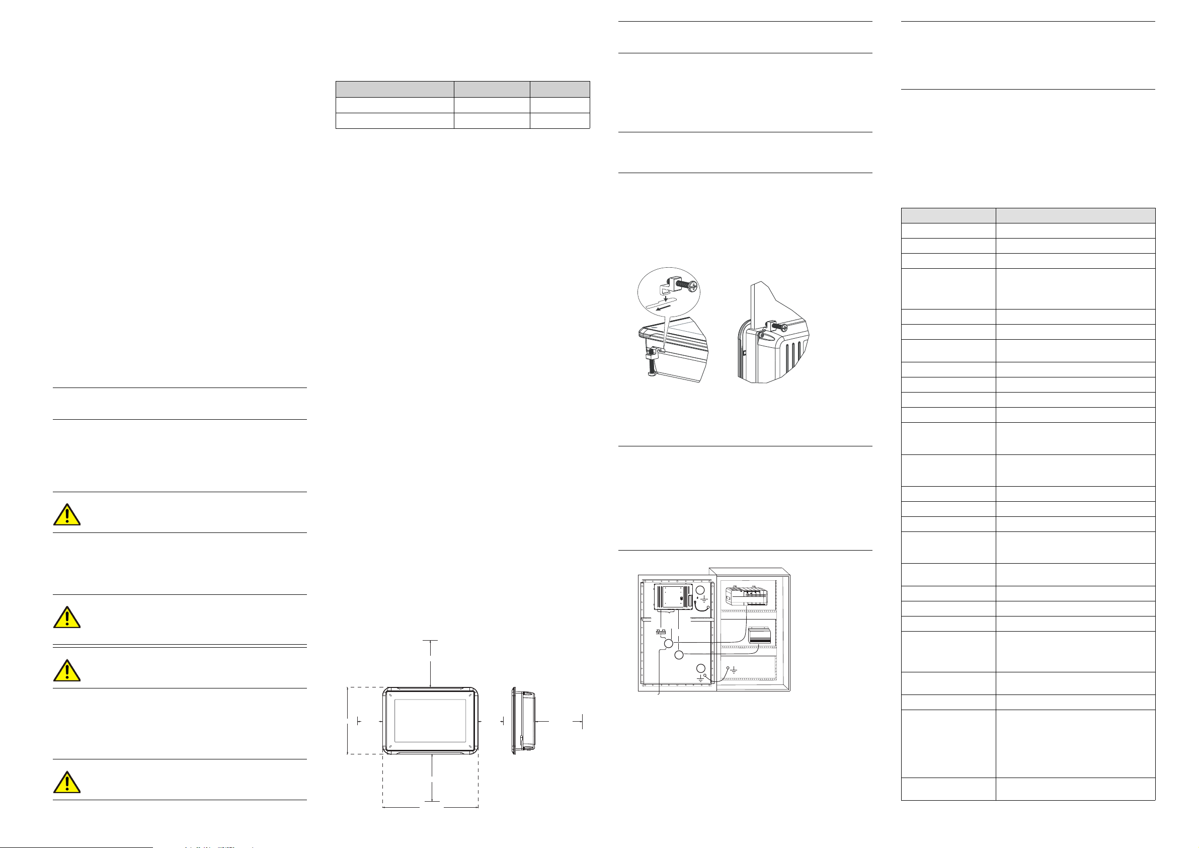
2Installation
2.1 SpaceRequirements
Maximum installation plate thickness: 11 mm
•
Space requirements in millimeters when installing the operator panel:
•
100 mm
143 mm
100 mm
204 mm
50 mm50 mm
100 mm
Note:
Thedimensionson the drawingarenot proportional.
2.2 Installation Process
The following is needed:
A Phillips/slot screwdriver
•
1.
Unpackand check the delivery. If damage is found, notify the supplier.
Note:
Placetheoperatorpanel on astablesurfaceduring installation.
Droppingthepanelorlettingitfallmaycausedamage.
2.
Use the cut out dimensions that are included on the outline drawing, found
in section Operator Panel Drawings and in the Technical Data table, to cut a
correct opening in the cabinet. A separate cut out drawing is available for
download from the Beijer Electronics web site.
3.
Secure the operator panel in position using all the fastening holes and the
provided brackets and screws:
x 4 0.5 - 1.0 Nm
4.
Connect the cables in the specified order,accordingto the drawing and steps
below.
Caution:
Ensurethattheoperatorpanelandthecontrollersystemhavethesame
•
electricalgrounding(referencevoltage level), otherwise errors in
communicationmayoccur.
Theoperatorpanelmustbebroughttoambienttemperaturebefore it
•
isstartedup. Ifcondensationforms, ensurethattheoperatorpanelis
drybeforeconnecting it to the power outlet.
Ensurethatthevoltageandpolarityofthepowersourceiscorrect.
•
Useonlyshieldedcommunicationcables.
•
Separatehighvoltage cablesfromsignalandsupply cables.
•
B
RS232/
RS422/
RS485
24V DC
C
D
A
Ethernet
– Connect cable A.
– Connect cable B, using an M5 screw and a grounding conductor (as
short as possible) with a cross-section of minimum 2.5 mm
– Connect cable C.
– Connect cable D. The recommended cross-section of the cable is
5.
Carefully removethe laminated film over the operator panel display, to avoid
1.5 mm
2
.
static electricity that coulddamage the panel.
Power
Controller
24V DC
Note:
OnlyforiXT7A panelswithpartnumber630000201:
Whenconnectingtheoperator panel to thepoweroutletforthe firsttime,
makesurenottointerrupt powerforaminimumof 48 hoursinordertocharge
thebatterycompletely. Afterthat,the batterymaybechargedpartly during
ashorterperiodoftime.
2.2.1 Connectionstothe Controller
Forinformation about the cables to be used when connecting the operator panel to
the controller,pleaserefer to the help file for the driver in question.
2.2.2 OtherConnectionsand Peripherals
Cables, peripheral equipment and accessories must be suitable for the application
and its environment. Forfurther details or recommendations, please refer to the
supplier.
3TechnicalData
Parameter
Frontpanel,W×H×D
Cutoutdimensions,W × H
Mountingdepth 43mm(143 mm includingclearance)
Standalonemounting
Frontpanelseal
Rearpanel seal
Touchscreenmaterial Polyesteronglass,resistive.
Touchscreenoperations 1million fingertouchoperations
Reversesidematerial Powder-coatedaluminum
Framematerial Powder-coated aluminum
Weight 0.8kg
Serialportfor
COM1RS232and
COM2RS422/RS485
Serialportfor
COM3RS232and
COM4RS422/RS485
Ethernet 1×10Base-T/100Base-T(shielded RJ 45)
USB 1×USBHost2.0, max outputcurrent200mA
Processor
Externalstoragemedia 1×SDcard(optional). Onlycompatible
Flashmemory
(applicationmemory)
MemoryRAM 128MB(DDR2)
LED
Realtime clock Yes(onchip)
(2)
Battery
Powerconsumptionat
ratedvoltage
Fuse
Powersupply
2
.
Display TFT-LCDwithLED backlight. 800×480pixels,
204×143×7mm
187×126mm
VESA75×75
Note: Maximumscrewlength for VESA
mountingis4mm. Usageoflongerscrews
mayleadtodamage.
IP65
IP20
Overlay: Autoflex EBA 180L
9-pinD-subcontactwithRS232RTS/CTS,
chassis-mountedfemalewithstandard
lockingscrews4-40UNC
9-pinD-subcontactwithRS232RTS/CTS,
chassis-mountedfemalewithstandard
lockingscrews4-40UNC
400MHzARM9
withthestandard SDformatwithup to 2GB
storagecapacity.
128MBSSD(NANDFlash)
1×blue/redsoftwareprogrammable
LithiumbatterytypeBR2032,soldered
orrechargeablebattery
InstrumentsPartNo. MS920-SEor similar),
soldered
6.0W
InternalDCfuse,2.0AT,5×20mm
+24VDC(18-32 V DC)
CE:Thepowersupply must conformwiththe
requirementsaccordingtoIEC60950and
IEC61558-2-4.
ULandcUL:Thepower supply must conform
withtherequirementsforclass II power
supplies.
64kcolors
iXT7A
(2)
(1)
.
(Seiko
 Loading...