


 Loading...
iX Panel TA150
Service & Maintenance Manual
MAEN014A, 2010-12 |
English |

Foreword
Service & Maintenance manual for iX Panel TA150
Foreword
This manual contains detailed information about iX Panel TA150, including descriptions of various actions that can be carried out in order to maintain or update the operator panel hardware and software.
The manual contains descriptions of basic maintenance and replacement of common parts in iX Panel TA150.
The manual assumes that the most recent versions of the system program (firmware) and iX Developer are used.
The following other manuals are available for iX Panel TA150:
iX Panel TA150 installation manual (MAEN011x) for information regarding installation.
iX Developer reference manual (MAEN831x) for a description of the configuration tool.
iX Developer user’s guide (MAEN832x) for function-based descriptions.
Order no: MAEN014A
Copyright © 2010-12 Beijer Electronics AB. All rights reserved.
The information in this document is subject to change without notice and is provided as available at the time of printing. Beijer Electronics AB reserves the right to change any information without updating this
publication. Beijer Electronics AB assumes no responsibility for any errors that may appear in this document. Read the entire installation manual prior to installing and using this equipment. Only qualified personnel may install, operate or repair this equipment. Beijer Electronics AB is not responsible for modified, altered or renovated equipment. Because the equipment has a wide range of applications, users must acquire the appropriate knowledge to use the equipment properly in their specific applications. Persons responsible
for the application and the equipment must themselves ensure that each application is in compliance with all relevant requirements, standards and legislation in respect to configuration and safety. Only parts and
accessories manufactured according to specifications set by Beijer Electronics AB may be used.
BEIJER ELECTRONICS AB SHALL NOT BE LIABLE TO ANYONE FOR ANY DIRECT, INDIRECT, SPECIAL, INCIDENTAL OR CONSEQUENTIAL DAMAGES RESULTING FROM THE INSTALLATION, USE OR REPAIR OF THIS EQUIPMENT, WHETHER ARISING IN TORT, CONTRACT, OR OTHERWISE. BUYER'S SOLE REMEDY SHALL BE THE REPAIR, REPLACEMENT, OR REFUND
OF PURCHASE PRICE, AND THE CHOICE OF THE APPLICABLE REMEDY SHALL BE AT THE SOLE DISCRETION OF BEIJER ELECTRONICS AB .
Beijer Electronics, MAEN014A

|
|
|
|
Contents |
Contents |
|
|
||
1 |
Safety Precautions ....................................................... |
5 |
||
|
1.1 |
General |
........................................................... |
5 |
|
1.2 |
During Installation .............................................. |
5 |
|
|
1.3 |
During Use ....................................................... |
6 |
|
|
1.4 |
Service and Maintenance ........................................ |
6 |
|
|
1.5 |
Dismantling and Scrapping ..................................... |
6 |
|
2 |
Introduction ............................................................. |
|
7 |
|
|
2.1 |
iX Panel TA150 .................................................. |
7 |
|
|
2.2 |
Maintenance ..................................................... |
8 |
|
|
2.3 |
Service and Repairs .............................................. |
8 |
|
|
2.4 |
Dismantling and Scrapping ..................................... |
8 |
|
|
2.5 |
Contact and Support ............................................ |
9 |
|
3 |
Installation ............................................................... |
|
10 |
|
|
3.1 |
Space Requirements ............................................. |
10 |
|
|
3.2 |
Installation Process .............................................. |
10 |
|
|
|
3.2.1 |
Connections to the Controller ................................ |
..13 |
|
|
3.2.2 |
Other Connections and Peripherals ........................... |
..13 |
4 |
Technical Data ........................................................... |
|
14 |
|
5 |
Chemical Resistance .................................................... |
15 |
||
|
5.1 |
Metal Casing ..................................................... |
15 |
|
|
5.2 |
Touch Screen and Overlay ....................................... |
16 |
|
|
|
5.2.1 |
Autotex F157/207 ............................................. |
..16 |
|
|
5.2.2 |
Touch Screen Surface .......................................... |
..17 |
|
|
5.2.3 |
Autoflex EB .................................................... |
..17 |
6 |
Hardware Tests |
.......................................................... |
18 |
|
7 |
Hardware Replacement ................................................. |
19 |
||
|
7.1 |
Mode Switches ................................................... |
19 |
|
|
7.2 |
Cables ............................................................. |
|
20 |
|
7.3 |
Replacing the Rear Cover ........................................ |
21 |
|
|
7.4 |
Replacing the Display/Display Cable .......................... |
22 |
|
|
|
7.4.1 |
Self Test of the Display ......................................... |
..23 |
|
|
7.4.2 |
Calibrating the Touch Screen .................................. |
..23 |
|
7.5 |
Replacing the Complete Front .................................. |
24 |
|
|
7.6 |
Replacing the Backlight ......................................... |
25 |
|
|
7.7 |
Available Spare Parts for iX Panel TA150 ....................... |
26 |
|
8 |
Service Menu ............................................................ |
|
27 |
|
|
8.1 |
Service Menu in an Empty Panel ............................... |
27 |
|
|
8.2 |
Service Menu in a Panel with Project ........................... |
27 |
|
|
8.3 |
Service Menu Options ........................................... |
27 |
|
|
|
8.3.1 |
IP Settings ..................................................... |
..27 |
|
|
8.3.2 |
Date/Time ..................................................... |
..28 |
|
|
8.3.3 |
Erase Project ................................................... |
..28 |
|
|
8.3.4 |
Touch Calibrate ............................................... |
..28 |
9 |
Hardware Self Test ...................................................... |
29 |
||
|
9.1 |
Self Test Items .................................................... |
30 |
|
Beijer Electronics, MAEN014A

|
|
|
Contents |
10 Additional Installation Tips ............................................ |
31 |
||
10.1 |
Grounding the Operator Panel ................................. |
31 |
|
10.2 |
Ethernet Connection in the Panel .............................. |
32 |
|
10.3 |
To Achieve Better EMC Protection ............................. |
33 |
|
10.4 |
Ambient Temperature ........................................... |
34 |
|
10.5 |
Safety |
............................................................. |
35 |
10.6 |
Galvanic ................................................Isolation |
36 |
|
10.7 |
Cable .............................and Bus Termination RS485 |
37 |
|
11 Fault Tracing ............................................................. |
|
38 |
|
12 Software .................................................................. |
|
40 |
|
12.1 |
General ...........................Information about Software |
40 |
|
|
12.1.1 .............................................. |
Software Products |
.40 |
12.2 |
Update .................................................Software |
41 |
|
|
12.2.1 .................................................... |
iX Developer |
.41 |
|
12.2.2 .......................................... |
Remote Access Viewer |
.41 |
|
12.2.3 ................................................ |
System Program |
.41 |
13 Environmental Aspects ................................................. |
43 |
||
13.1 |
General ................................Environmental Aspects |
43 |
|
13.2 |
Environmental .................Impact of the Operator Panels |
43 |
|
|
13.2.1 ....................................... |
Mechanical Components |
.43 |
|
13.2.2 ...................................................... |
Electronics |
.43 |
13.3 |
Recycling ......................................................... |
44 |
|
13.4 |
Environmental ..................................Impact Report |
44 |
|
Beijer Electronics, MAEN014A

Safety Precautions
1 Safety Precautions
Both the installer and the owner and/or operator of the operator panel must read and understand this installation manual.
1.1General
•Read the safety precautions carefully.
•Check the delivery for transportation damage. If damage is found, notify the supplier as soon as possible.
•Do not use the operator panel in an environment with high explosive hazards.
•The supplier is not responsible for modified, altered or reconstructed equipment.
•Use only parts and accessories manufactured according to specifications of the supplier.
•Read the installation and operating instructions carefully before installing, using or repairing the operator panel.
•Never allow fluids, metal filings or wiring debris to enter any openings in the operator panel. This may cause fire or electrical shock.
•Only qualified personnel may operate the operator panel.
•Storing the operator panel where the temperature is lower/higher than recommended in this manual can cause the LCD display liquid to congeal/become isotopic.
•The LCD display liquid contains a powerful irritant. In case of skin contact, wash immediately with plenty of water. In case of eye contact, hold the eye open, flush with plenty of water and get medical attention.
•The figures in this manual serves an illustrative purpose. Because of the many variables associated with any particular installation, the supplier cannot assume responsibility for actual use based on the figures.
•The supplier neither guarantees that the operator panel is suitable for your particular application, nor assumes responsibility for your product design, installation or operation.
1.2During Installation
•The operator panel is designed for stationary installation on a plane surface, where the following conditions are fulfilled:
–no high explosive risks
–no strong magnetic fields
–no direct sunlight
–no large, sudden temperature changes
•Install the product according to the accompanying installation instructions.
•Ground the product according to the accompanying installation instructions.
•Only qualified personnel may install the operator panel.
•Separate the high voltage, signal and supply cables.
•Make sure that the voltage and polarity of the power source is correct before connecting the product to the power outlet.
•Peripheral equipment must be appropriate for the application and location.
Beijer Electronics, MAEN014A |
5 |

Safety Precautions
1.3 During Use
• Keep the operator panel clean.
• Emergency stop and other safety functions may not be controlled from the operator panel.
• Do not use too much force or sharp objects when touching the keys, touch screen etc.
1.4 Service and Maintenance
• Only qualified personnel should carry out repairs.
• The agreed warranty applies.
• Before carrying out any cleaning or maintenance operations, disconnect the equipment from the electrical supply.
• Clean the display and surrounding front cover with a soft cloth and mild detergent.
• Replacing the battery incorrectly may result in explosion. Only use batteries recommended by the supplier.
1.5 Dismantling and Scrapping
•The operator panel or parts thereof shall be recycled according to local regulations.
•The following components contain substances that might be hazardous to health and the environment: lithium battery, electrolytic capacitor and display.
Beijer Electronics, MAEN014A |
6 |

Introduction
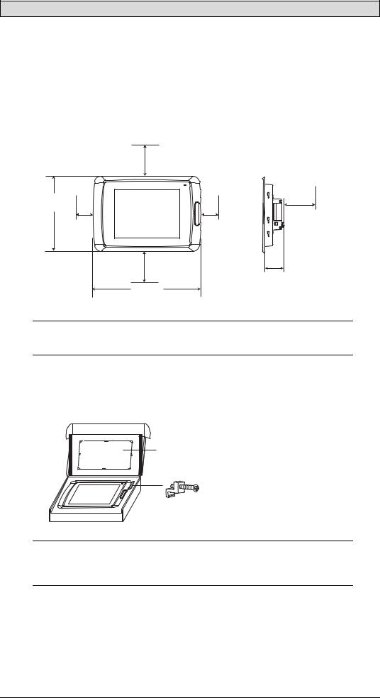
2 Introduction
This manual describes how to maintain the iX Panel TA150.
The functions available in iX Developer depend on which operator panel model is used.
2.1iX Panel TA150
The following drawings are available for iX Panel TA150:
•Outline drawing
•Panel cut-out
Beijer Electronics, MAEN014A |
7 |

Introduction
2.2Maintenance
Carefully read the instructions before beginning maintenance on the operator panel.
•Only qualified personnel should carry out maintenance.
•The agreed warranty and license agreements apply.
•Any damage to the operator panel caused by personnel invalidates the warranty.
•Before carrying out any cleaning or maintenance operations, disconnect the operator panel from the power supply.
•Clean the display and surrounding front cover with a soft cloth and mild detergent. Recommended cleaning fluids for the display are water and IPA (Isopropyl Alcohol or Hexane).
•Replacing the battery incorrectly may result in explosion. Only use batteries recommended by the supplier.
•A 6-month warranty on all service parts is provided.
Maintenance personnel are permitted to carry out the following actions:
•Replacing the Rear Cover
•Replacing the Display/Display Cable
•Replacing the Complete Front
•Replacing the Backlight
2.3 Service and Repairs
• Only accredited companies are permitted to perform service and repairs.
• If a non-accredited company conducts any kind of service or repair, the agreed warranty will be invalidated.
• If training is required, contact the supplier.
• All maintenance should be performed in a 15-30 °C temperature range.
• Any damage to the operator panel caused by personnel invalidates the warranty.
• Contracts with customers supersede the information in this document.
2.4 Dismantling and Scrapping
•The operator panel, or parts thereof, should be recycled according to local regulations.
•The following components contain substances that might be hazardous to health and the environment: lithium battery, electrolytic capacitor, display.
Beijer Electronics, MAEN014A |
8 |

Introduction
2.5Contact and Support
If you want to report a fault or have a question about the operator panels, please contact your local supplier or fill out the form on the web site.
1.Enter the web site www.beijerelectronics.com and select Support.
2.Select Contact in the menu. Make sure to provide information about type number, serial number, environment and an installation description.
The form will be sent to the manufacturer’s help desk and they will answer your question or register your improvement/fault.
To ensure quick resolution, provide as many details as possible in your report. Include the date and time when the problem occurred, a description of what you were trying to do, the detailed steps you took that led up to the problem, and details about any error messages received.
Beijer Electronics, MAEN014A |
9 |
Installation
3 Installation
3.1Space Requirements
•Installation plate thickness: 1.5 - 9.0 mm (0.06 - 0.35 inch)
•Space requirements when installing the operator panel:
100 mm
(4.0 inch)
304 mm |
|
|
(11.97 inch) |
|
100 mm |
|
|
|
50 mm |
50 mm |
(4.0 inch) |
(2.0 inch) |
(2.0 inch) |
|
|
100 mm |
|
|
(4.0 inch) |
60 mm |
|
|
|
|
398 mm |
(2.36 inch) |
|
|
|
|
(15.67 inch) |
|
Caution:
The openings on the enclosure are for air convection. Do not cover these openings.
3.2Installation Process
1. Unpack and check the delivery. If damage is found, notify the supplier.
Panel cut out 355.5 x 278.5 mm (14.0 x 10.96 inch)
x 14
Note:
Place the operator panel on a stable surface during installation.
Dropping it or letting it fall may cause damage.
Beijer Electronics, MAEN014A |
10 |
Installation
2.Place the panel cut out where the operator panel is to be situated, draw along the outer sides of the holes and cut according to the markings.
3.Secure the operator panel in position, using all the fastening holes and the provided brackets and screws:
x 14
0.5 - 1.0 Nm
Beijer Electronics, MAEN014A |
11 |

Installation
4.Connect the cables in the specified order, according to the drawing and steps below.
Caution:
•Ensure that the operator panel and the controller system have the same electrical grounding (reference voltage level), otherwise errors in communication may occur.
•The operator panel must be brought to ambient temperature before it is started up. If condensation forms, ensure that the operator panel is dry before connecting it to the power outlet.
•Ensure that the voltage and polarity of the power source is correct.
•Use only shielded communication cables.
•Separate high voltage cables from signal and supply cables.
B |
CARD CF |
|
Controller |
|
|
|
|
|
|
1 |
|
RS422/RS485 |
24V DC |
24V DC |
|
|
RS232 |
|
|
|
C |
|
|
|
|
|
|
|
|
D |
|
|
|
A |
|
|
Ethernet |
|
|
–Connect cable A.
–Connect cable B, using an M5 screw and a grounding conductor (as short as possible) with a cross-section of minimum 2.5 mm2.
–Connect cable C.
–Connect cable D.
5.Carefully remove the laminated film over the operator panel display, to avoid static electricity that could damage the panel.
Beijer Electronics, MAEN014A |
12 |

Installation
3.2.1Connections to the Controller
For information about the cables to be used when connecting the operator panel to the controller, please refer to the help file for the driver in question.
3.2.2Other Connections and Peripherals
Cables, peripheral equipment and accessories must be suitable for the application and its environment. For further details or recommendations, please refer to the supplier.
Beijer Electronics, MAEN014A |
13 |

Technical Data
4 Technical Data
Parameter |
iX Panel TA150 |
Front panel, W x H x D |
398 x 304 x 6 mm |
|
|
Mounting depth |
60 mm (160 mm including clearance) |
|
|
Front panel seal |
IP 66 |
|
|
Rear panel seal |
IP 20 |
|
|
Keyboard |
Touch screen: Polyester on glass, 1 million finger touch |
material/Front |
operations. Overlay: Autotex F157 or F207*. |
panel |
|
|
|
Reverse side |
Powder-coated aluminum |
material |
|
|
|
Weight |
3.7 kg |
|
|
Serial port |
25-pin D-sub contact, chassis-mounted female with |
RS422/RS485 |
standard locking screws 4-40 UNC |
|
|
Serial port RS232C |
9-pin D-sub contact, male with standard locking screws 4-40 |
|
UNC |
|
|
Ethernet |
2 x shielded RJ 45 |
|
|
USB |
Host type A (USB 2.0), max output current 500 mA |
|
|
Memory slots |
1 x SD card |
|
|
Real time clock |
±30 PPM + error because of ambient temperature. Total |
|
maximum error: 77 seconds/month at 25 °C. |
|
Temperature coefficient: -0.034±0.006 ppm/°C2 |
|
Rechargeable battery. |
|
|
Power consumption |
Normal: 1.2 A |
at rated voltage |
Maximum: 1.7 A |
|
|
Display |
TFT-LCD.1024 x 768 pixels, 64K colors. |
|
CCFL backlight lifetime at the ambient temperature of |
|
+25 °C: >35,000 h. |
|
|
Active area of |
304.1 x 228.1 mm |
display, W x H |
|
|
|
Fuse |
Internal DC fuse, 3.15 AT, 5 x 20 mm |
|
|
Power supply |
+24 V DC (20 - 30 V DC). Power supply connector. |
|
CE: The power supply must conform with the requirements |
|
according to IEC 60950 and IEC 61558-2-4. |
|
UL and cUL: The power supply must conform with the |
|
requirements for class II power supplies. |
|
|
Ambient |
Vertical installation: 0 ° to +50 °C |
temperature |
Horizontal installation: 0 ° to +40 °C |
|
|
Storage temperature |
-20 ° to +70 °C |
|
|
Relative humidity |
5 - 85 % non-condensed |
|
|
Approvals and |
Information is available on the web site |
certifications |
www.beijerelectronics.com |
|
|
* See section Chemical Resistance for more information.
Beijer Electronics, MAEN014A |
14 |
Loading...