


1 |
MODBUS Programmable I/O NA-9379 |
FnIO S-Series |
|
|
|
|
|
MODBUS Programmable I/O
NA-9379
User Manual
Version 1.03
2014 CREVIS Co.,Ltd
Copyright(C) CREVIS Co.,Ltd Support +82-31-899-4599 URL : www.crevis.co.kr

2 |
MODBUS Programmable I/O NA-9379 |
FnIO S-Series |
|
|
|
|
|
DOCUMENT CHANGE SUMMARY
REV |
PAGE |
REMARKS |
DATE |
EDITOR |
|
|
|
|
|
1.0 |
New Document |
Draft |
2013/04/05 |
JE Kang |
|
|
|
|
|
1.01 |
Reorganize |
Draft |
2014/03/25 |
YMKIM |
|
|
|
|
|
1.02 |
|
Modify the Pin Description |
2014/05/08 |
YMKIM |
|
|
|
|
|
1.03 |
Reorganize2 |
Draft |
2014/05/29 |
YMKIM |
|
|
|
|
|
|
|
|
|
|
|
|
|
|
|
|
|
|
|
|
|
|
|
|
|
|
|
|
|
|
|
|
|
|
|
|
|
|
|
|
|
|
|
|
|
Copyright(C) CREVIS Co.,Ltd Support +82-31-899-4599 URL : www.crevis.co.kr

3 |
MODBUS Programmable I/O NA-9379 |
FnIO S-Series |
|
|
|
|
|
CONTENTS
1. |
Important Notes ......................................................................................................................................................... |
7 |
|
|
1.1. |
Safety Instruction ...................................................................................................................................... |
8 |
|
1.1.1. |
Symbols......................................................................................................................................................... |
8 |
|
1.1.2. |
Safety Notes................................................................................................................................................ |
8 |
|
1.1.3. |
Certification (TBD)..................................................................................................................................... |
8 |
2. |
S-Series System........................................................................................................................................................... |
9 |
|
|
2.1. |
Electrical Interface..................................................................................................................................... |
9 |
|
2.2. |
I/O Process Image Map ....................................................................................................................... |
10 |
3. |
Specification................................................................................................................................................................ |
11 |
|
|
3.1. |
General Specification............................................................................................................................. |
11 |
|
3.2. |
Interface Specification........................................................................................................................... |
12 |
4. |
Module Description................................................................................................................................................. |
13 |
|
|
4.1. |
NA-9379 (MODBUS Programmable I/O)...................................................................................... |
13 |
|
4.2. |
LED Indicator............................................................................................................................................. |
14 |
|
3.2.1. |
Indicator Status and Flash Rates...................................................................................................... |
14 |
|
3.2.2. |
Module Status LED (MOD) ................................................................................................................. |
15 |
|
3.2.3. |
Network Status LED (NET) .................................................................................................................. |
15 |
|
3.2.4. |
PLC Run/Stop Status LED (RUN)...................................................................................................... |
15 |
|
3.2.5. |
Extension Module Status LED (I/O) ................................................................................................ |
16 |
|
3.2.6. |
Field Power Status LED ........................................................................................................................ |
16 |
|
3.3. |
RJ-45 Socket , RS232/485 Port......................................................................................................... |
17 |
|
3.4. |
Toggle Switch , Push Button ............................................................................................................. |
17 |
|
|
|
|
Copyright(C) |
CREVIS Co.,Ltd Support +82-31-899-4599 URL : www.crevis.co.kr |
|
|

4 |
MODBUS Programmable I/O NA-9379 |
FnIO S-Series |
3.5. |
RTB Terminal Block ................................................................................................................................ |
18 |
3.6. |
Pin Description......................................................................................................................................... |
18 |
3.7. |
Dimension .................................................................................................................................................. |
19 |
4. Mechanical Setup..................................................................................................................................................... |
20 |
|
4.3. |
Inserting and Removing the Module............................................................................................. |
20 |
4.4. |
Removable Terminal Block (RTB)..................................................................................................... |
21 |
4.5. |
Method of Wiring................................................................................................................................... |
21 |
5. Various Functions of PIO (With IO Guide Pro) ........................................................................................... |
22 |
|
5.1. |
Connect IO Guide Pro (MODBUS Serial)...................................................................................... |
22 |
5.2. |
Confirmation of Network Information. ......................................................................................... |
25 |
5.3. |
BootP/DHCP Setting.............................................................................................................................. |
27 |
5.4. |
Setup IP Address..................................................................................................................................... |
29 |
5.5. |
Serial Communication Settings......................................................................................................... |
32 |
5.6. |
Memory Reset .......................................................................................................................................... |
34 |
5.7. |
RTC(Real Time Clock) Function......................................................................................................... |
35 |
6. Programing the PIO (CoDeSys).......................................................................................................................... |
36 |
|
6.1. |
Download and Install the CoDeSys ................................................................................................ |
36 |
6.2. |
The Basic Configuration CoDeSys ................................................................................................... |
37 |
6.2.1. |
Installation of XML ................................................................................................................................. |
37 |
6.2.2. |
Created Project ........................................................................................................................................ |
41 |
6.2.3. |
CoDeSys User Interface........................................................................................................................ |
42 |
6.2.4. |
Setup I/O .................................................................................................................................................... |
43 |
6.3. |
MODBUS TCP Setting ........................................................................................................................... |
46 |
Copyright(C) |
CREVIS Co.,Ltd Support +82-31-899-4599 URL : www.crevis.co.kr |
|

|
5 |
|
MODBUS Programmable I/O NA-9379 |
FnIO S - Series |
|
|
|
|
|
|
|
|
6.4. |
Network Variable .................................................................................................................................... |
50 |
||
|
6.5. |
Download and Monitoring ................................................................................................................. |
53 |
||
7. |
Upgrade Firmware ................................................................................................................................................... |
54 |
|||
|
7.1. |
Using IAP over Ethernet....................................................................................................................... |
54 |
||
8. |
Trouble Shooting |
...................................................................................................................................................... |
|
56 |
|
|
8.1. |
How to diagnose by LED indicator................................................................................................. |
56 |
||
|
8.2. |
How to diagnose when device couldn’t communicate network |
.......................................57 |
||
APPENDIX A - MODBUS INTERFACE........................................................................................................................ |
58 |
||||
|
A.1 |
MODBUS Interface Register / Bit Map.......................................................................................... |
58 |
||
|
A.2 |
MODBUS Transmission Mode........................................................................................................... |
59 |
||
|
A.2.1. |
RTU Transmission Mode ..................................................................................................................... |
59 |
||
|
A.2.2. |
ASCII Transmission Mode................................................................................................................... |
59 |
||
|
A.3 |
Supported MODBUS Function Codes............................................................................................ |
59 |
||
|
A.3.1. |
1 (0x01) |
Read Coils................................................................................................................................ |
60 |
|
|
A.3.2. |
2 (0x02) |
Read Discrete Inputs .......................................................................................................... |
61 |
|
|
A.3.3. |
3 (0x03) |
Read Holding Registers..................................................................................................... |
62 |
|
|
A.3.4. |
4 (0x04) |
Read Input Registers .......................................................................................................... |
63 |
|
|
A.3.5. |
5 (0x05) |
Write Single Coil................................................................................................................... |
64 |
|
|
A.3.6. |
6 (0x06) |
Write Single Register.......................................................................................................... |
65 |
|
|
A.3.7. |
8 (0x08) |
Diagnostics.............................................................................................................................. |
66 |
|
|
A.3.8. |
15 (0x0F) Write Multiple Coils.......................................................................................................... |
69 |
||
|
A.3.9. |
16 (0x10) Write Multiple Registers................................................................................................. |
70 |
||
|
A.3.10. |
23 (0x17) Read/Write Multiple Registers .................................................................................... |
71 |
||
|
|
|
|
||
Copyright(C) |
CREVIS Co.,Ltd Support +82-31-899-4599 URL : www.crevis.co.kr |
|
|||

6 |
MODBUS Programmable I/O NA-9379 |
FnIO S-Series |
|
|
|
|
|
A.4 |
MODBUS Special Register Map........................................................................................................ |
72 |
A.4.1. |
Adapter Register Mapping................................................................................................................. |
72 |
A.4.2. |
Adapter Identification Special Register (0x1000, 4096) ........................................................ |
72 |
A.4.3. |
Adapter Watchdog Time, other Time Special Register (0x1020, 4128)......................... |
73 |
A.4.4. |
Adapter Information Special Register (0x1100, 4352) ........................................................... |
74 |
A.4.5. |
Adapter Setting Special Register (0x1600, 5632)..................................................................... |
75 |
A.4.6. |
Expansion Slot Information Special Register (0x2000, 8192) ............................................. |
76 |
A.5 |
Example ....................................................................................................................................................... |
78 |
A.5.1. |
Example of Input Process Image(Input Register) Map.......................................................... |
78 |
A.5.2. |
Example of Output Process Image(Output Register) Map.................................................. |
80 |
A.6 |
Error Response......................................................................................................................................... |
82 |
A.7 |
MODBUS Reference............................................................................................................................... |
83 |
APPENDIX B - Product List ........................................................................................................................................... |
84 |
|
Copyright(C) CREVIS Co.,Ltd Support +82-31-899-4599 URL : www.crevis.co.kr

7 |
MODBUS Programmable I/O NA-9379 |
FnIO S-Series |
|
|
|
|
|
1. Important Notes
Solid state equipment has operational characteristics differing from those of electromechanical equipment.
Safety Guidelines for the Application, Installation and Maintenance of Solid State Controls describes some important differences between solid state equipment and hard-wired electromechanical devices.
Because of this difference, and also because of the wide variety of uses for solid state equipment, all persons responsible for applying this equipment must satisfy themselves that each intended application of this equipment is acceptable.
In no event will CREVIS be responsible or liable for indirect or consequential damages resulting from the use or application of this equipment.
The examples and diagrams in this manual are included solely for illustrative purposes. Because of the many variables and requirements associated with any particular installation, CREVIS cannot assume responsibility or liability for actual use based on the examples and diagrams.
Warning!
If you don’t follow the directions, it could cause a personal injury, damage to the equipment or explosion
•Do not assemble the products and wire with power applied to the system. Else it may cause an electric arc, which can result into unexpected and potentially dangerous action by field devices. Arching is explosion risk in hazardous locations. Be sure that the area is non-hazardous or remove system power appropriately before assembling or wiring the modules.
•Do not touch any terminal blocks or IO modules when system is running. Else it may cause the unit to an electric shock or malfunction.
•Keep away from the strange metallic materials not related to the unit and wiring works should be controlled by the electric expert engineer. Else it may cause the unit to a fire, electric shock or malfunction.
Caution!
If you disobey the instructions, there may be possibility of personal injury, damage to equipment or explosion. Please follow below Instructions.
•Check the rated voltage and terminal array before wiring. Avoid the circumstances over 55 of temperature. Avoid placing it directly in the sunlight.
•Avoid the place under circumstances over 85% of humidity.
•Do not place Modules near by the inflammable material. Else it may cause a fire.
•Do not permit any vibration approaching it directly.
•Go through module specification carefully, ensure inputs, output connections are made with the specifications. Use standard cables for wiring.
•Use Product under pollution degree 2 environment.
Copyright(C) CREVIS Co.,Ltd Support +82-31-899-4599 URL : www.crevis.co.kr
8 |
MODBUS Programmable I/O NA-9379 |
FnIO S-Series |
|
|
|
|
|
1.1. Safety Instruction
1.1.1. Symbols
Identifies information about practices or circumstances that can cause an explosion in a hazardous environment, which may lead to personal injury or death property damage or economic loss.
Identifies information that is critical for successful application and understanding of the product.
Identifies information about practices or circumstances that can lead to personal injury, property damage, or economic loss.
Attentions help you to identity a hazard, avoid a hazard, and recognize the consequences.
1.1.2. Safety Notes
The modules are equipped with electronic components that may be destroyed by electrostatic discharge. When handling the modules, ensure that the environment (persons, workplace and packing) is well grounded. Avoid touching conductive components.
1.1.3. Certification (TBD)
Copyright(C) CREVIS Co.,Ltd Support +82-31-899-4599 URL : www.crevis.co.kr

9 |
MODBUS Programmable I/O NA-9379 |
FnIO S-Series |
|
|
|
|
|
2. S-Series System
2.1.Electrical Interface
• Network Adapter Module
The Network Adapter Module forms the link between the field bus and the field devices with the Expansion Modules. The connection to different field bus systems can be established by each of the corresponding Network Adapter Module, e.g. for SyncNet, PROFIBUS, CANopen, DeviceNet, Ethernet/IP, CC-Link, MODBUS/Serial, MODBUS/TCP etc.
• Expansion Module
The Expansion Modules are supported a variety of input and output field devices. There are digital and analog input/output modules and special function modules.
• Two types of Message
Service Messaging / I/O Messaging
Copyright(C) CREVIS Co.,Ltd Support +82-31-899-4599 URL : www.crevis.co.kr
10 |
MODBUS Programmable I/O NA-9379 |
FnIO S-Series |
|
|
|
|
|
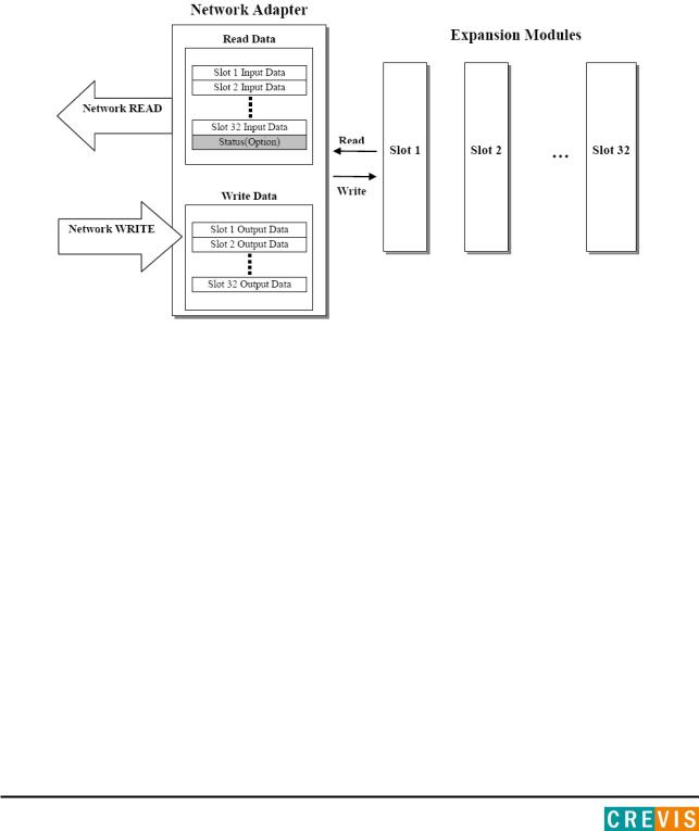
2.2.I/O Process Image Map
An expansion module may have 3 types of data as I/O data, configuration parameter and memory register. The data exchange between network adapter and expansion modules is done via an I/O process image data by internal-protocol. The following figure shows the data flow of process image between network adapter and expansion modules.
Copyright(C) CREVIS Co.,Ltd Support +82-31-899-4599 URL : www.crevis.co.kr
11 |
MODBUS Programmable I/O NA-9379 |
FnIO S-Series |
|
|
|
|
|
3. Specification
3.1.General Specification
General Specification
|
|
Supply voltage : 24Vdc nominal |
|
|
System Power |
Supply voltage range : 11~28.8Vdc |
|
|
Protection : Output current limit (Min. 1.5A) |
||
|
|
||
|
|
Reverse polarity protection |
|
|
|
|
|
|
Power Dissipation |
110mA typical @ 24Vdc |
|
|
|
|
|
|
Current for I/O Module |
1.5A @5Vdc |
|
|
|
|
|
|
Isolation |
System power to internal logic : Non-isolation |
|
|
|
System power I/O driver : Isolation |
|
|
|
|
|
|
Field Power |
Supply voltage : 24Vdc nominal |
|
|
Supply voltage range : 11~28Vdc |
||
|
|
||
|
|
|
|
|
Max. Current Field Power Contact |
DC 10A Max. |
|
|
|
|
|
|
Weight |
172g |
|
|
|
|
|
|
Module Size |
54mm x 99mm x 70mm |
|
|
|
|
|
|
Environment Condition |
|
|
|
|
|
|
|
Environmental Specifications |
|
|
|
Operating Temperature |
-20 ~60 |
|
|
Storage Temperature |
-40 ~85 |
|
|
Relative Humidity |
5% ~ 90% non-condensing |
|
|
Mounting |
DIN rail |
|
|
|
|
|
|
General Specifications |
|
|
|
Shock Operating |
IEC 60068-2-6 |
|
|
|
|
|
|
|
Based on IEC 60068-2-6 |
|
|
|
Sine Vibration |
|
|
|
- |
10 ~ 25 Hz : 0.5mm |
|
|
- |
50 ~ 150 Hz : 5g |
|
|
- |
150 ~ 1000 Hz : 2g |
|
Vibration/shock resistance |
- |
Sweep Rate : 1 Oct/min, 50 cycles |
|
Sine Vibration |
|
|
|
|
|
|
|
|
- |
10 ~ 25 Hz : 0.03 g²/Hz |
|
|
- |
25 ~ 50 Hz : 0.05 g²/Hz |
|
|
- |
50 ~ 150 Hz : 0.15 g²/Hz |
|
|
- |
150 ~ 1000 Hz : 0.01 g²/Hz |
|
|
- |
Test time : 5hrs for each test |
|
|
|
|
|
EMC resistance burst/ESD |
EN 61000-6-2 : 2005 |
|
|
EN 61000-6-4/ALL : 2011 |
||
|
|
||
|
|
|
|
|
Installation Pos. / Protect. Class |
Variable/IP20 |
|
|
|
|
|
|
Product Certifications |
TBD |
|
|
|
|
|
Copyright(C) CREVIS Co.,Ltd Support +82-31-899-4599 URL : www.crevis.co.kr

12 |
MODBUS Programmable I/O NA-9379 |
FnIO S-Series |
|
|
|
|
|
3.2.Interface Specification
Programmable Specification
|
Programming |
CoDeSys V3.5 SP3 Patch 1 |
|
|
|
|
|
|
Program Memory |
512 Kbytes |
|
|
|
|
|
|
|
512 Kbytes |
|
|
Data Memory |
%IW0~%IW639 (640 word Input and Internal memory) |
|
|
%QW0~%QW639 (640 word Output and Internal memory) |
||
|
|
||
|
|
%MW0~%MW639 (640 word Internal memory) |
|
|
Non-Volatile Memory |
32 Kbytes (Retain : 16Kbytes, Flag : 16Kbytes |
|
|
|
|
|
|
Run-Time system |
Multiple PLC Task |
|
|
|
|
|
|
Program Languages |
IEC 61131-3 (LD, IL, ST, FBD, SFC) |
|
|
|
|
|
|
RTC |
Retain Time : 6 days |
|
|
Accuracy : <2min/month |
||
|
|
||
|
|
|
|
|
Max. Task |
2 |
|
|
|
|
|
|
Max. Cycle Task |
2 |
|
|
|
|
|
|
Max. Status Task |
1 |
|
|
|
|
|
|
Process Time |
3us (100Instruction) |
|
|
|
|
|
|
Interface Specification |
|
|
|
Adapter Type |
Master & Slave Node (MODBUS TCP) |
|
|
|
|
|
|
Max. Expansion Module |
32 slots |
|
|
|
|
|
|
Max. Input Size |
126 Words (252 Byte) |
|
|
|
|
|
|
Max. Output Size |
126 Words (252 Byte) |
|
|
|
|
|
|
Max. Nodes |
Limited by Ethernet Specification |
|
|
|
|
|
|
Baudrate |
10/100Mps, Auto-negotiation, Full Duplex |
|
|
|
|
|
|
Interface Connector |
RJ-45 socket * 2pcs |
|
|
|
|
|
|
Protocol |
MODBUS TCP, DHCP, BOOTP, SNMP |
|
|
|
|
|
|
Max. Socket |
18 (UDP : 6, TCP : 12, TCP_LISTEN : 6) |
|
|
|
|
|
|
Other Serial Port |
RS232/485 for MODBUS RTU, Touch Pannel or IOGuide |
|
|
|
|
|
|
|
Node : |
1(default) |
|
|
Baudrate : |
38400(default) |
|
Serial Configuration (RS232/485) |
Data bit : |
8(default) |
|
|
Parity bit : No parity(default) |
|
|
|
Stop bit : |
1(default) |
|
|
|
|
|
|
4 LEDs (NET LED is Not used) |
|
|
|
1 Green/Red, Module Status (MOD) |
|
|
Indicator |
1 Green/Red, Run Status (RUN) |
|
|
|
1 Green/Red, Extension Module Status (I/O) |
|
|
|
1 Green, Field Power Status |
|
|
|
|
|
Copyright(C) CREVIS Co.,Ltd Support +82-31-899-4599 URL : www.crevis.co.kr

13 |
MODBUS Programmable I/O NA-9379 |
FnIO S-Series |
|
|
|
|
|
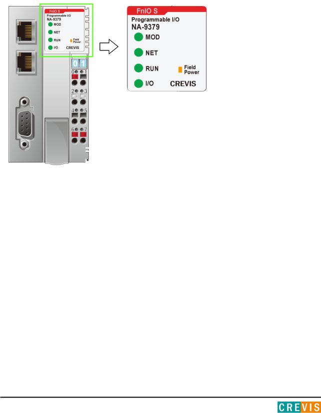
4.Module Description
4.1. NA-9379 (MODBUS Programmable I/O)
The modules are not hot swappable and should be not removed in power on condition.
Copyright(C) CREVIS Co.,Ltd Support +82-31-899-4599 URL : www.crevis.co.kr
14 |
MODBUS Programmable I/O NA-9379 |
FnIO S-Series |
|
|
|
|
|
4.2.LED Indicator
|
LED No. |
|
|
LED Function / |
|
|
LED Color |
|
|
|
|
Description |
|
|
|
||
|
|
|
|
|
|
|
|
|
|
MOD |
|
Module Status |
|
Green/Red |
|||
|
|
|
|
|
|
|||
|
NET |
|
Not Used |
- |
|
|||
|
|
|
|
|
|
|||
|
RUN |
|
Error Status |
|
Green/Red |
|||
|
|
|
|
|
|
|||
|
I/O |
|
Extension module Status |
|
Green/Red |
|||
|
|
|
|
|
|
|||
|
Field Power |
|
Field Power Enable |
|
Green |
|||
|
|
|
|
|
|
|
|
|
3.2.1.Indicator Status and Flash Rates
|
LED is: |
|
|
Constantly on |
|
|
|
|
|
||
|
|
|
|
|
|
|
LED Off |
|
Constantly off |
||
|
|
|
|
|
|
|
LED Flickering |
|
Equal on and off times with a frequency of approximately 10 Hz: on for approximately |
||
|
|
50ms and off for approximately 50ms. |
|||
|
|
|
|
||
|
|
|
|
|
|
|
LED Blinking |
|
Equal on and off times with a frequency of approximately 2, 5Hz: on for approximately |
||
|
|
200ms followed by off for approximately 200ms. |
|||
|
|
|
|
||
|
|
|
|
|
|
|
LED Single flash |
|
One short flash (approximately 200ms) followed by a long off phase (approximately |
||
|
|
1000ms) |
|||
|
|
|
|
||
|
|
|
|
|
|
|
|
|
|
A sequence of two short flashes (approximately 200ms), separated by an off phase |
|
|
LED Double flash |
|
(approximately 200ms). The sequence is finished by a long off phase (approximately |
||
|
|
|
|
1000ms). |
|
|
|
|
|
|
|
|
|
|
|
A sequence of three short flashes (approximately 200ms), separated by an off phase |
|
|
LED Triple flash |
|
(approximately 200ms). The sequence is finished by a long off phase (approximately |
||
|
|
|
|
1000ms). |
|
|
|
|
|
|
|
Copyright(C) CREVIS Co.,Ltd Support +82-31-899-4599 URL : www.crevis.co.kr

15 |
MODBUS Programmable I/O NA-9379 |
|
|
|
|
3.2.2.Module Status LED (MOD)
FnIO S-Series
|
State |
|
|
LED is : |
|
|
To indicate : |
|
|
|
|
|
|
|
|||
|
|
|
|
|
|
|
|
|
No Power |
|
Off |
|
No power is supplied to the unit. |
||||
|
|
|
|
|
||||
Device Operational |
|
Green |
|
The unit is operating in normal condition. |
||||
|
|
|
|
|
|
|
|
|
Device in Standby |
|
Blinking Green |
|
The EEPROM parameter is not initialized yet. |
||||
|
|
Serial Number is zero value (0x00000000) |
||||||
|
|
|
|
|
|
|
||
IAP Mode |
|
Flashing Green |
|
IAP Mode : Available for firmware download using FireFox. |
||||
|
|
|
|
|
|
|
|
|
Minor Fault |
|
Blinking Red |
|
The unit has occurred recoverable fault in self-testing. |
||||
|
|
- EEPROM checksum fault |
||||||
|
|
|
|
|
|
|
||
Unrecoverable Fault |
|
Red |
|
The unit has occurred unrecoverable fault in self-testing. |
||||
|
|
- Firmware fault |
||||||
|
|
|
|
|
|
|
||
3.2.3.Network Status LED (NET)
|
State |
|
|
LED is : |
|
|
To indicate : |
|
|
|
|
|
|
|
|||
|
|
|
|
|
|
|
|
|
Not Used
3.2.4.PLC Run/Stop Status LED (RUN)
|
State |
|
|
LED is : |
|
|
To indicate : |
|
|
|
|
|
|
|
|||
|
|
|
|
|
|
|
|
|
Not Programmed |
|
OFF |
|
Not Power is supplied or the unit or Not programmed |
||||
|
|
|
|
|
||||
Run |
|
ON |
|
PLC Run |
||||
|
|
|
|
|
||||
Stop |
|
Blinking Green |
|
PLC Stop |
||||
|
|
|
|
|
||||
Error |
|
Blinking Red |
|
Failure of Module Configuration |
||||
|
|
|
|
|
|
|
|
|
Copyright(C) CREVIS Co.,Ltd Support +82-31-899-4599 URL : www.crevis.co.kr

16 |
MODBUS Programmable I/O NA-9379 |
|
|
|
|
3.2.5. Extension Module Status LED (I/O)
FnIO S-Series
|
State |
|
|
LED is : |
|
|
To indicate : |
|
|
|
|
|
|
|
|||
|
|
|
|
|
|
|
|
|
|
Not Powered |
|
Off |
|
Device has no expansion module or may not be powered |
|||
|
No Expansion Module |
|
|
|||||
|
|
|
|
|
|
|
||
|
|
|
|
|
|
|
||
|
On-line, |
|
Flashing Green |
|
Extension module is normal but does not exchanging I/O data |
|||
|
Do not Exchanging I/O |
|
|
(Passed the expansion module configuration). |
||||
|
|
|
|
|
||||
|
|
|
|
|
|
|
|
|
|
Connection, |
|
Green |
|
Exchanging I/O data |
|||
|
Run Exchanging IO |
|
|
|||||
|
|
|
|
|
|
|
||
|
|
|
|
|
|
|
|
|
|
Connection fault |
|
|
|
|
One or more expansion module occurred in fault state. |
||
|
|
Red |
|
- Changed expansion module configuration. |
||||
|
during exchanging IO |
|
|
|||||
|
|
|
|
|
- expansion module communication failure. |
|||
|
|
|
|
|
|
|
||
|
|
|
|
|
|
|
|
|
|
|
|
|
|
|
|
Failed to initialize expansion module |
|
|
|
|
|
|
|
|
- Detected invalid expansion module ID. |
|
|
Expansion |
|
Flashing Red |
|
- Overflowed Input / Output Size |
|||
|
Configuration Failed |
|
|
- Too many expansion module |
||||
|
|
|
|
|
||||
|
|
|
|
|
|
|
- Initial protocol failure |
|
|
|
|
|
|
|
|
- Mismatch vendor code between adapter and expansion module. |
|
|
|
|
|
|
|
|
|
|
3.2.6.Field Power Status LED
State |
LED is : |
To indicate : |
|
|
|
Not Supplied Field Power |
Off |
Not supplied 24V dc field power, 5Vdc System Power. |
|
|
|
Supplied Field Power |
Green |
Supplied 24V dc field power, 5Vdc System Power. |
|
|
|
Copyright(C) CREVIS Co.,Ltd Support +82-31-899-4599 URL : www.crevis.co.kr

17 |
MODBUS Programmable I/O NA-9379 |
FnIO S-Series |
|
|
|
|
|
3.3. RJ-45 Socket , RS232/485 Port
|
RJ-45 |
|
|
Signal Name |
|
|
Description |
|
|
|
|
|
|
|
|||
1 |
|
|
TD+ |
|
Transmit + |
|||
|
|
|
|
|
|
|||
2 |
|
|
TD- |
|
Transmit - |
|||
|
|
|
|
|
|
|||
3 |
|
|
RD+ |
|
Receive + |
|||
|
|
|
|
|
|
|
||
4 |
|
- |
|
|
|
|
||
|
|
|
|
|
|
|
||
5 |
|
- |
|
|
|
|
||
|
|
|
|
|
|
|||
6 |
|
|
RD- |
|
Receive - |
|||
|
|
|
|
|
|
|
||
7 |
|
- |
|
|
|
|
||
|
|
|
|
|
|
|
||
8 |
|
- |
|
|
|
|
||
|
|
|
|
|
|
|
||
|
Case |
|
Shield |
|
|
|
||
|
|
|
|
|
|
|
|
|
|
RS 232/485 |
|
|
Signal Name |
|
|
Description |
|
|
|
|
|
|
|
|||
1 |
|
- |
|
|
|
|
||
|
|
|
|
|
|
|||
2 |
|
|
RXD |
|
RS232 RXD |
|||
|
|
|
|
|
|
|||
3 |
|
|
TXD |
|
RS232 TXD |
|||
|
|
|
|
|
|
|
||
4 |
|
- |
|
|
|
|
||
|
|
|
|
|
|
|||
5 |
|
|
GND |
|
RS232 GND |
|||
|
|
|
|
|
|
|||
6 |
|
|
D+ |
|
RS 485 D+ |
|||
|
|
|
|
|
|
|
||
7 |
|
- |
|
|
|
|
||
|
|
|
|
|
|
|||
8 |
|
|
D- |
|
RS485 D- |
|||
|
|
|
|
|
|
|
||
9 |
|
- |
|
|
|
|
||
|
|
|
|
|
|
|
|
|
3.4. Toggle Switch , Push Button
|
Toggle Switch Status |
|
|
Module is |
|
|
Description |
|
|
|
|
|
|
|
|||
|
UP |
|
RUN |
|
PLC Run |
|||
|
|
|
|
|
|
|
|
|
|
DOWN |
|
STOP |
|
PLC Stop |
|||
|
|
|
(Fault Action is performed) |
|||||
|
|
|
|
|
|
|
||
|
|
|
|
|
|
|
|
|
|
Push Button |
|
Module is |
|
Description |
|
Press and release. |
|
Reset |
|
Reset the PLC and then stop. |
|
|
|
|
|
|
|
Hold down and reset |
|
IAP mode |
|
Available for firmware download |
|
the power. |
|
|
using FireFox |
|
|
|
|
|
||
|
|
|
|
|
|
Copyright(C) CREVIS Co.,Ltd Support +82-31-899-4599 URL : www.crevis.co.kr

18 |
MODBUS Programmable I/O NA-9379 |
FnIO S-Series |
|
|
|
|
|
3.5. RTB Terminal Block
|
Pin |
|
|
Signal Description |
|
|
Signal Description |
|
|
Pin |
|
|
|
|
|
|
|
|
|
||||
0 |
|
|
System Power 24V |
|
System Power 0V |
1 |
|
||||
|
|
|
|
|
|
|
|
||||
2 |
|
|
F.G |
|
F.G |
3 |
|
||||
|
|
|
|
|
|
|
|
||||
4 |
|
|
Field Power 0V |
|
Field Power 0V |
5 |
|
||||
|
|
|
|
|
|
|
|
||||
6 |
|
|
Field Power 24V |
|
Field Power 24V |
7 |
|
||||
|
|
|
|
|
|
|
|
|
|
|
|
-System Power: The power for starting up CPU.
-Field Power: The power for input and output line.
Do not use an incorrect voltage/frequency!
The use of an incorrect supply voltage or frequency can cause severe damage to the component.
3.6. Pin Description
Communication between the Network adapter and the expansion module as well as system / field power supply of the bus modules is carried out via the internal bus. It is comprised of 6 data pin and 2 field power pin.
No. |
Name |
Description |
1 |
System Vcc |
System supply voltage (5V dc). |
|
|
|
|
|
2 |
System GND |
System Ground. |
|
|
|
|
|
3 |
Token Output |
Token output port of Processor module. |
|
|
|
|
|
4 |
Serial Output |
Transmitter output port of Processor |
|
module. |
|||
|
|
||
|
|
|
|
5 |
Serial Input |
Receiver input port of Processor module. |
|
|
|
|
|
6 |
Reserved |
Reserved for bypass Token. |
|
|
|
|
|
7 |
Field GND |
Field Ground. |
|
|
|
|
|
8 |
Field Vcc |
Field supply voltage (24Vdc). |
Do not touch data and field power pins in order to avoid soiling and damage by ESD noise.
Copyright(C) CREVIS Co.,Ltd Support +82-31-899-4599 URL : www.crevis.co.kr
19 |
MODBUS Programmable I/O NA-9379 |
FnIO S-Series |
|
|
|
|
|
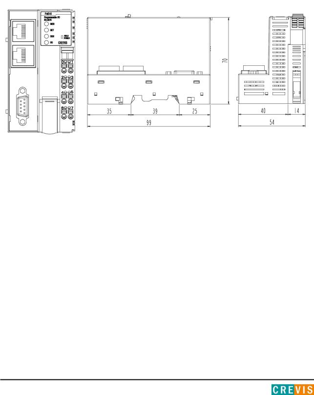
3.7. Dimension
(mm)
Copyright(C) CREVIS Co.,Ltd Support +82-31-899-4599 URL : www.crevis.co.kr
20 |
MODBUS Programmable I/O NA-9379 |
FnIO S-Series |
|
|
|
|
|
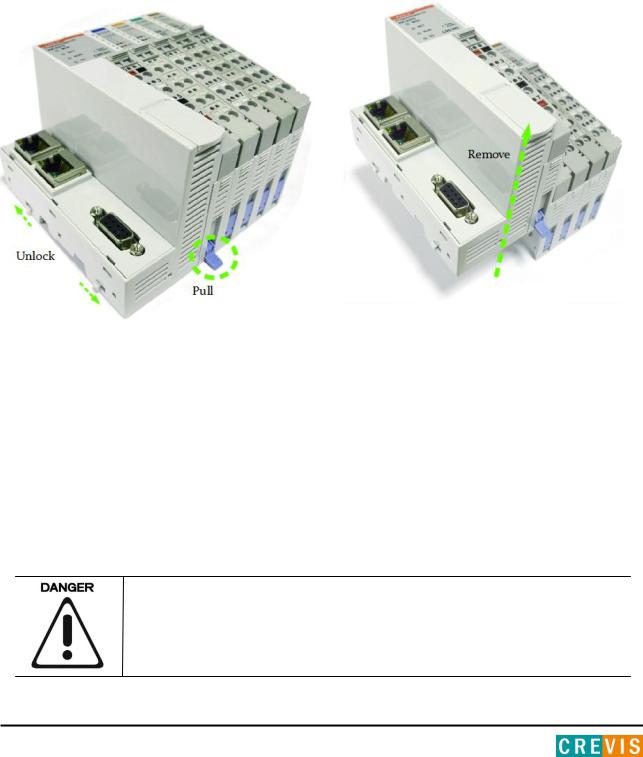
4.Mechanical Setup
4.3.Inserting and Removing the Module.
As above figure in order to safeguard the FnIO module from jamming, it should be fixed onto the DIN rail with locking level. To do so, fold on the upper of the locking lever.
To pull out the FnIO module, unfold the locking lever as below figure.
Before work is done on the components, the voltage supply must be turned off.
Copyright(C) CREVIS Co.,Ltd Support +82-31-899-4599 URL : www.crevis.co.kr
21 |
MODBUS Programmable I/O NA-9379 |
FnIO S-Series |
|
|
|
|
|
4.4.Removable Terminal Block (RTB)
4.5.Method of Wiring.
Connecting or removing the cable by pushing the terminal button for the relevant points.
The use of an incorrect supply voltage or frequency can cause severe damage to the component.
Copyright(C) CREVIS Co.,Ltd Support +82-31-899-4599 URL : www.crevis.co.kr
22 |
MODBUS Programmable I/O NA-9379 |
FnIO S-Series |
|
|
|
|
|
5. Various Functions of PIO (With IO Guide Pro)
Crevis IO Guide Pro is compatible with the PIO(NA-9379).
The basic parameter set-up and configuration for the PIO is available via the IO Guide Pro.
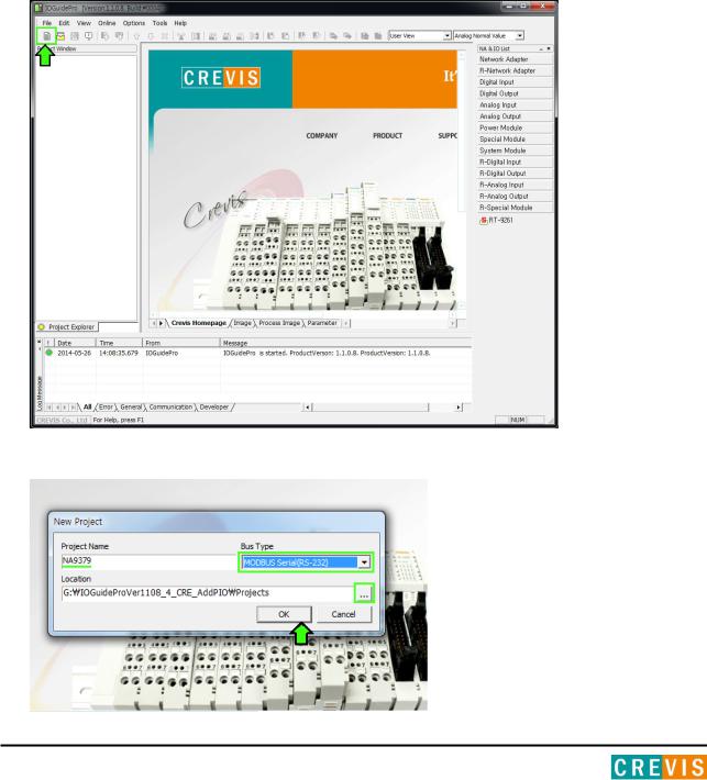
5.1.Connect IO Guide Pro (MODBUS Serial)
(1)Installation program-IO Guide Pro that provides CREVIS(www.crevis.co.kr).
(2)Open the IO Guide and Click on the ‘New project’ Icon.
(2) Write the ‘Project Name’ and Select of bus type Specify the local and Click on the ‘OK’ button.
Copyright(C) CREVIS Co.,Ltd Support +82-31-899-4599 URL : www.crevis.co.kr

23 |
MODBUS Programmable I/O NA-9379 |
FnIO S-Series |
|
|
|
|
|
(1) After creating a project and click the ‘Automatic scan’ Icon.
(4) Write the value(Port, node, Baudrate) click the ‘Automatic scan’ button.
Copyright(C) CREVIS Co.,Ltd Support +82-31-899-4599 URL : www.crevis.co.kr

24 |
MODBUS Programmable I/O NA-9379 |
FnIO S-Series |
|
|
|
|
|
(1) After the scan completes, click the ‘OK’ button.
(1) It is ready to use the IO Guide Pro.
Copyright(C) CREVIS Co.,Ltd Support +82-31-899-4599 URL : www.crevis.co.kr

25 |
MODBUS Programmable I/O NA-9379 |
FnIO S-Series |
|
|
|
|
|
5.2.Confirmation of Network Information.
You can see by checking the IP Address , Subnet Mask, Gate Way, Mac Address of NA-9379 .
*IP Address : Also known as an "IP number" or simply an "IP," this is a code made up of numbers separated by three dots that identifies a particular computer on the Internet. Every computer, whether it be a Web server or the computer you're using right now, requires an IP address to connect to the Internet. IP addresses consist of four sets of numbers from 0 to 255, separated by three dots.
*Subnet Mask : A subnet mask is a number that defines a range of IP addresses that can be used in a network. (It is not something you wear on your head to keep subnets out.) Subnet masks are used to designate sub networks, or subnets, which are typically local networks LANs that are connected to the Internet. Systems within the same subnet can communicate directly with each other, while systems on different subnets must communicate through a router.
*Gate Way : A gateway is either hardware or software that acts as a bridge between two networks so that data can be transferred between a number of computers.
*Mac Address : A MAC address is a hardware identification number that uniquely identifies each device on a network. The MAC address is manufactured into every network card, such as an Ethernet card or Wi-Fi card, and therefore cannot be changed.
(1) Run ‘[Crevis] -> [IOGuidePro] -> [Protocol Messenger] -> [Modbus]’
Copyright(C) CREVIS Co.,Ltd Support +82-31-899-4599 URL : www.crevis.co.kr

26 |
MODBUS Programmable I/O NA-9379 |
|
|
|
|
(2)Write the value of each.
*Protocol : Modbus RTU
*ComPort : User Port / Baudrate : 38400(default) *Address(Hex) : 1600 (IP Address Register)
1602 (IP Subnet Mask Register)
1604 (Gate way Register)
1610 (Mac Address Register) *Function(Dec) : 03, Read Holding Registers
FnIO S-Series
(3)After clicking the ‘send’ button and confirm the necessary information.
If you choose to 'ByteDec', More easy to see.
Copyright(C) CREVIS Co.,Ltd Support +82-31-899-4599 URL : www.crevis.co.kr
 Loading...