

Page 1
User Manual
VIRTUALIZER 3D FX2000
High-Performance 3D Multi-Engine Eects Processor
Page 2
2 VIRTUALIZER 3D FX2000 User Manual
Table of Contents
Thank you .......................................................................2
Important Safety Instructions ...................................... 3
Legal Disclaimer ............................................................. 3
Limited Warranty ...........................................................3
1. Introduction ............................................................... 5
2. Eects Algorithms ..................................................... 7
3. Operation ................................................................. 13
4. Applications ............................................................. 17
5. MIDI Functions of the FX2000 ................................ 19
6. Installation ............................................................... 19
7. Appendix .................................................................. 21
8. Specications ........................................................... 25
Thank you
In purchasing the BEHRINGER VIRTUALIZER 3D you have acquired an extremely
ecient multi-eects processor that oers rst class reverberation eects and a
number of other algorithms. The FX2000 has 71 new eects types, and thanks to
its logically structured user interface, it can be used easily and intuitively.
Page 3
3 VIRTUALIZER 3D FX2000 User Manual
“Where to Buy“, or you can contact the MUSIC Group o ce
or replacement product will be returned to the user freight
Important Safety
Instructions
Terminals marked with this symbol carr y
electrical current of su cient magnitude
to constitute risk of electric shock. Useonly
high-quality commercially-available speaker cables with
¼"TS plugs pre-installed. Allother installation or
modi cation should be performed only by
quali edpersonnel.
This symbol, wherever it appears,
alertsyou to the presence of uninsulated
dangerous voltage inside the
enclosure-voltage that may be su cient to constitute a
risk ofshock.
This symbol, wherever it appears,
alertsyou to important operating and
maintenance instructions in the
accompanying literature. Please read the manual.
Caution
To reduce the risk of electric shock, do
not remove the top cover (or the rear
section). No user serviceable parts inside. Refer servicing
to quali ed personnel.
Caution
To reduce the risk of re or electric shock,
do not expose this appliance to rain and
moisture. The apparatus shall not be exposed to dripping
or splashing liquids and no objects lled with liquids, such
as vases, shall be placed on the apparatus.
Caution
These service instructions are for use
by quali ed ser vice personnel only.
Toreduce the risk of electric shock do not per form any
servicing other than that contained in the operation
instructions. Repairs have to be performed by quali ed
servicepersonnel.
1. Read these instructions.
2. Keep these instructions.
3. Heed all warnings.
4. Follow all instructions.
5. Do not use this apparatus near water.
6. Clean only with dry cloth.
7. Do not block any ventilation openings. Install in
accordance with the manufacturer’s instructions.
8. Do not install near any heat sources such as
radiators, heat registers, stoves, or other apparatus
(including ampli ers) that produce heat.
9. Do not defeat the safety purpose of the polarized
or grounding-type plug. A polarized plug has two blades
with one wider than the other. A grounding-type plug
has two blades and a third grounding prong. The wide
blade or the third prong are provided for your safety. Ifthe
provided plug does not t into your outlet, consult an
electrician for replacement of the obsolete outlet.
10. Protect the power cord from being walked on or
pinched particularly at plugs, convenience receptacles,
and the point where they exit from the apparatus.
11. Use only attachments/accessories speci ed by
themanufacturer.
12. Use only with the
cart, stand, tripod, bracket,
or table speci ed by the
manufacturer, orsold with
the apparatus. When a cart
is used, use caution when
moving the cart/apparatus
combination to avoid
injury from tip-over.
13. Unplug this apparatus during lightning storms or
when unused for long periods of time.
14. Refer all servicing to quali ed service personnel.
Servicing is required when the apparatus has been
damaged in any way, such as power supply cord or plug
is damaged, liquid has been spilled or objects have fallen
into the apparatus, the apparatus has been exposed
to rain or moisture, does not operate normally, or has
beendropped.
15. The apparatus shall be connected to a MAINS socket
outlet with a protective earthing connection.
16. Where the MAINS plug or an appliance coupler is
used as the disconnect device, the disconnect device shall
remain readily operable.
LEGAL DISCLAIMER
TECHNICAL SPECIFICATIONS AND APPEARANCE
ARE SUBJECT TO CHANGE WITHOUT NOTICE.
THEINFORMATION CONTAINED HEREIN IS CORRECT
AT THE TIME OF PRINTING. ALL TRADEMARKS ARE
THE PROPERTY OF THEIR RESPECTIVE OWNERS.
MUSICGROUP ACCEPTS NO LIABILITY FOR ANY
LOSS WHICH MAY BE SUFFERED BY ANY PERSON
WHO RELIES EITHER WHOLLY OR IN PART UPON
ANY DESCRIPTION, PHOTOGRAPH OR STATEMENT
CONTAINED HEREIN. COLORS AND SPECIFICATIONS
MAY VARY FROM ACTUAL PRODUCT. MUSIC GROUP
PRODUCTS ARE SOLD THROUGH AUTHORIZED
FULLFILLERS AND RESELLERS ONLY. FULLFILLERSAND
RESELLERS ARE NOT AGENTS OF MUSICGROUP
AND HAVE ABSOLUTELY NO AUTHORITY TO BIND
MUSICGROUP BY ANY EXPRESS OR IMPLIED
UNDERTAKING OR REPRESENTATION. THIS MANUAL
IS COPYRIGHTED. NO PART OF THIS MANUAL MAY
BE REPRODUCED OR TRANSMITTED IN ANY FORM
OR BY ANY MEANS, ELECTRONIC OR MECHANICAL,
INCLUDING PHOTOCOPYING AND RECORDING OF ANY
KIND, FOR ANY PURPOSE, WITHOUT THE EXPRESS
WRITTEN PERMISSION OF MUSICGROUPIPLTD.
ALL RIGHTS RESERVED.
© 2011 MUSICGroupIPLtd.
Trident Chambers, Wickhams Cay, P.O. Box 146,
Road Town, Tortola, British Virgin Islands
LIMITED WARRANTY
§ 1 Warranty
(1) This limited warranty is valid only if you purchased
the product from a MUSIC Group Authorized Reseller in
the country of purchase. A list of authorized resellers can
be found on BEHRINGER’s website behringer. com under
closest to you.
(2) MUSICGroup* warrants the mechanical and
electronic components of this product to be free of defects
in material and workmanship if used under normal
operating conditions for a period of one (1) year from
the original date of purchase (see the Limited Warranty
terms in §4 below), unless a longer minimum warranty
period is mandated by applicable local laws. If the product
shows any defects within the speci ed warranty period
and that defect is not excluded under §4, MUSICGroup
shall, at its discretion, either replace or repair the product
using suitable new or reconditioned product or parts.
Incase MUSICGroup decides to replace the entire product,
thislimited warranty shall apply to the replacement
product for the remaining initial warranty period, i.e.,
one (1) year (or otherwise applicable minimum warranty
period) from the date of purchase of the original product.
(3) Upon validation of the warranty claim, the repaired
prepaid by MUSICGroup.
(4) Warranty claims other than those indicated above
are expressly excluded.
PLEASE RETAIN YOUR SALES RECEIPT. IT IS YOUR PROOF
OF PURCHASE COVERING YOUR LIMITED WARRANTY.
THIS LIMITED WARRANT Y IS VOID WITHOUT SUCH PROOF
OFPURCHASE.
§ 2 Online registration
Please do remember to register your new BEHRINGER
equipment right after your purchase at behringer. com
under “Support” and kindly read the terms and conditions
of our limited warranty carefully. Registeringyour
purchase and equipment with us helps us process
your repair claims quicker and more e ciently.
Thankyouforyour cooperation!
§ 3 Return materials authorization
(1) To obtain warranty ser vice, please contact the
retailer from whom the equipment was purchased.
Should your MUSIC Group Authorized Reseller not be
located in your vicinity, you may contact the MUSICGroup
Authorized Ful ller for your country listed under
Page 4
4 VIRTUALIZER 3D FX2000 User Manual
“Support” at behringer. com. Ifyour country is not
listed, please check if your problem can be dealt with
by our “OnlineSuppor t” which may also be found under
“Support” at behringer. com. Alternatively,please submit
an online warranty claim at behringer. com BEFORE
returning the product. All inquiries must be accompanied
by a description of the problem and the serial number
of the product. Afterverifying the product’s warranty
eligibility with the original sales receipt, MUSICGroup
will then issue a ReturnMaterials Authorization
(“RMA”)number.
(2) Subsequently, the product must be returned in
its original shipping carton, together with the return
authorization number to the address indicated by
MUSICGroup.
(3) Shipments without freight prepaid will not
beaccepted.
§ 4 Warranty Exclusions
(1) This limited warranty does not cover consumable
parts including, but not limited to, fuses and batteries.
Where applicable, MUSICGroup warrants the valves or
meters contained in the product to be free from defects in
material and workmanship for a period of ninety (90) days
from date of purchase.
(2) This limited warranty does not cover the product
if it has been electronically or mechanically modi ed
in any way. If the product needs to be modi ed or
adapted in order to comply with applicable technical
or safety standards on a national or local level, in any
country which is not the country for which the product
was originally developed and manufactured, this
modi cation/adaptation shall not be considered a defect
in materials or workmanship. Thislimited warranty does
not cover any such modi cation/adaptation, regardless
of whether it was carried out properly or not. Under the
terms of this limited warranty, MUSICGroup shall not
be held responsible for any cost resulting from such a
modi cation/adaptation.
(3) This limited warranty covers only the product
hardware. It does not cover technical assistance for
hardware or software usage and it does not cover
any software products whether or not contained in
the product. Any such software is provided “AS IS”
unless expressly provided for in any enclosed software
limitedwarranty.
(4) This limited warranty is invalid if the factory-
applied serial number has been altered or removed from
theproduct.
(5) Free inspections and maintenance/repair work
are expressly excluded from this limited warranty, in
particular, if caused by improper handling of the product
by the user. This also applies to defects caused by normal
wear and tear, in par ticular, of faders, crossfaders,
potentiometers, keys/buttons, guitar strings, illuminants
and similar parts.
(6) Damage/defects caused by the following conditions
are not covered by this limited warranty:
• improper handling, neglect or failure to operate the
unit in compliance with the instructions given in
BEHRINGER user or service manuals;
• connection or operation of the unit in any way
that does not comply with the technical or safety
regulations applicable in the country where the
product is used;
• damage/defects caused by acts of God/Nature
(accident, re, ood, etc) or any other condition that
is beyond the control of MUSICGroup.
(7) Any repair or opening of the unit carried out by
unauthorized personnel (user included) will void the
limitedwarranty.
(8) If an inspection of the product by MUSICGroup
shows that the defect in question is not covered by the
limited warranty, the inspection costs are payable by
thecustomer.
(9) Products which do not meet the terms of this
limited warranty will be repaired exclusively at the buyer’s
expense. MUSICGroup or its authorized service center will
inform the buyer of any such circumstance. If the buyer
fails to submit a written repair order within 6 weeks after
noti cation, MUSICGroup will return the unit C.O.D. with
a separate invoice for freight and packing. Such costs will
also be invoiced separately when the buyer has sent in a
written repair order.
(10) MUSIC Group Authorized Resellers do not sell new
products directly in online auctions. Purchasesmade
through an online auction are on a “buyer beware” basis.
Online auction con rmations or sales receipts are not
accepted for warranty veri cation and MUSICGroup will
not repair or replace any product purchased through an
online auction.
§ 5 Warranty transferability
This limited warranty is extended exclusively to the
original buyer (customer of authorized reseller) andis
not transferable to anyone who may subsequently
purchase this product. No other person (reseller,etc.)
shallbe entitled to give any warranty promise on behalf
of MUSICGroup.
§ 6 Claim for damage
Subject only to the operation of mandatory applicable
local laws, MUSICGroup shall have no liability to the buyer
under this warranty for any consequential or indirect
loss or damage of any kind. In no event shall the liability
of MUSICGroup under this limited warranty exceed the
invoiced value of the product.
§ 7 Limitation of liability
This limited warranty is the complete and exclusive
warranty between you and MUSICGroup. It supersedes
all other written or oral communications related to this
product. MUSICGroup provides no other warranties for
this product.
§ 8 Other warranty rights and
nationallaw
(1) This limited warranty does not exclude or limit the
buyer’s statutory rights as a consumer in any way.
(2) The limited warranty regulations mentioned herein
are applicable unless they constitute an infringement of
applicable mandatory local laws.
(3) This warranty does not detract from the seller’s
obligations in regard to any lack of conformity of the
product and any hidden defect.
§ 9 Amendment
Warranty service conditions are subject to change without
notice. For the latest warranty terms and conditions
and additional information regarding MUSICGroup’s
limited warranty, please see complete details online at
behringer. com.
* MUSICGroup Macao Commercial O shore Limited of
RuedePequim No. 202-A, Macau Finance Centre 9/J, Macau,
including all MUSICGroup companies
Page 5

5 VIRTUALIZER 3D FX2000 User Manual
1. Introduction
In order to generate an extremely natural reverberation, we at BEHRINGER
have developed new kinds of algorithms for virtual acoustics. These algorithms
will help you calculate all room and reverberation parameters with absolutely
professional quality and naturalness.
In spite of this extensive and calculation-intensive work performed by the
24-bit processor in the FX2000, the VIRTUALIZER 3D is very easy to handle.
Changingparameters to achieve a specic sound is simple. There are 100 presets
available to store your own programs.
The FX2000 includes excellent reverb and delay programs, but that’s not all.
Besides the classic plate reverb simulations, the VIRTUALIZER 3D will impress
you with its excellent modulation eects (like chorus, anger and phaser),
whichwere extended to include special variations like a musical pitch shifter,
atremolo, and a rotary speaker simulation. The FX2000’s dynamic and psycho-
acoustic eects allow you to do without a number of additional pieces of
equipment. TheFX2000 also oers you a series of distortion and amplication
sounds that are combined with a speaker simulation. Thus, as a guitarist in
recording situations, you can achieve an excellent sound on tape or hard disk,
even without a speaker cabinet. Besides its logical and simple operation,
theVIRTUALIZER 3D’s technical equipment is also impressive. The following
points ensure signal processing at a professional level:
• Extremely low-noise and exact 24-bit A/D and D/A converters.
• A professional sample rate of 46 kHz guarantees a high signal resolution for
a frequency response of 20 Hz to 20 kHz.
• The 24-bit processor features dual engine software; these two sections
process audio input independently.
◊ Please always use the original packaging to avoid damage due to
storage or shipping.
◊ Never let unsupervised children play with the FX2000 or with
its packaging.
◊ Please dispose of all packaging materials in an environmentally-
friendly fashion.
The BEHRINGER VIRTUALIZER 3D requires one standard 19" rack unit of space
(1¾"). Please leave an additional 4" installation depth to allow connections at
the rear side.
Make sure that there is adequate ventilation and do not place the VIRTUALIZER 3D
on top of an amplier, which could cause overheating.
◊ Before connecting the VIRTUALIZER 3D to the mains, carefully check
that your equipment is set to the correct voltage:
The fuse holder on the female mains connector has 3 triangular markings,
withtwo of these triangles opposing each other. The VIRTUALIZER 3D is set to
the operating voltage printed next to these markers and can be set to another
voltage by turning the fuse holder by 180°. CAUTION: This instruction
does not apply to export models exclusively designed, e.g. for
120-Voperation!
Connection to the mains is made by a mains cable with an IEC receptacle that
complies with the required safety regulations.
◊ Please make sure that the unit is grounded at all times. For your own
protection, you should never tamper with the grounding of the cable
or the unit itself. The unit shall always be connected to a mains socket
outlet with a protective earthing connection.
• As for all BEHRINGER products, the highest quality components and controls
are used.
◊ The following instructions will give you a brief run-down on the
terminology and functions of the VIRTUALIZER 3D. After reading,
please store this manual in a safe place for future reference.
1.1 The concept
BEHRINGER uses an uncompromising selection of components. The heart of the
BEHRINGER VIRTUALIZER 3D is a 24-bit DSP, which, due to its exceptional technical
specications, is regarded as one of the nest building blocks. With it come the
rst class 24-bit A/D-D/A converters, guaranteeing a precise conversion of audio
signals. Narrow-range tolerance resistances and capacitors, high-grade switches,
and other selected components are all very high in quality.
The VIRTUALIZER 3D was manufactured on the basis of SMD technology
(SurfaceMounted Device). The use of sub-miniature building blocks known from
space ights allows not only an ex treme packing density but also ensures an
increased dependability. The FX2000 was manufactured under ISO9000 certied
management system.
1.2 Before you get started
The VIRTUALIZER 3D was carefully packed in the factory to ensure safe transport.
Nevertheless, if the box shows signs of damage, please check the equipment
immediately for any signs of external damage.
◊ Damaged units should NEVER be sent directly to us. Please inform the
dealer from whom you acquired the unit immediately as well as the
transportation company from which you took delivery of the unit.
Otherwise, all claims for replacement/repair may be rendered invalid.
◊ To assure optimal protection of your FX2000 during use or transport,
we recommend utilizing a carrying case.
◊ Installation and operation of this equipment must be carried out by
competent staf f only. Both before and after installation, the staff using
the equipment should make sure that it is properly grounded since
otherwise electrostatic discharge etc. can lead to an impairment of its
operation. For more information, see chapter 6 “Installation”.
The BEHRINGER VIRTUALIZER 3D is equipped with electronically servo-balanced
inputs and outputs. The circuit design features automatic hum suppression for
balanced signals and thus ensures trouble-free operation, even at the highest
operating levels. Externally induced mains hum, etc. can therefore be eectively
suppressed. The automatic servo-function recognizes the presence of unbalanced
connectors and adjusts the nominal level internally to avoid level dierences
between the input and output signals (6-dB correction).
The MIDI connectors (IN/OUT/THRU) are standard DIN plug connections. The data
communication is isolated from ground by opto-couplers.
1.3 Online registration
Please register your new BEHRINGER equipment right after your purchase
by visiting http://behringer.com and read the terms and conditions of our
warrantycarefully.
Should your BEHRINGER product malfunction, it is our intention to have it
repaired as quickly as possible. To arrange for warranty service, please contact
the BEHRINGER retailer from whom the equipment was purchased. Shouldyour
BEHRINGER dealer not be located in your vicinity, you may directly contact
one of our subsidiaries. Corresponding contact information is included in the
original equipment packaging (Global Contact Information/European Contac t
Information). Should your country not be listed, please contact the distributor
nearest you. A list of distributors can be found in the support area of our website
(http://behringer.com).
Registering your purchase and equipment with us helps us process your repair
claims more quickly and eciently.
Thank you for your cooperation!
Page 6
6 VIRTUALIZER 3D FX2000 User Manual
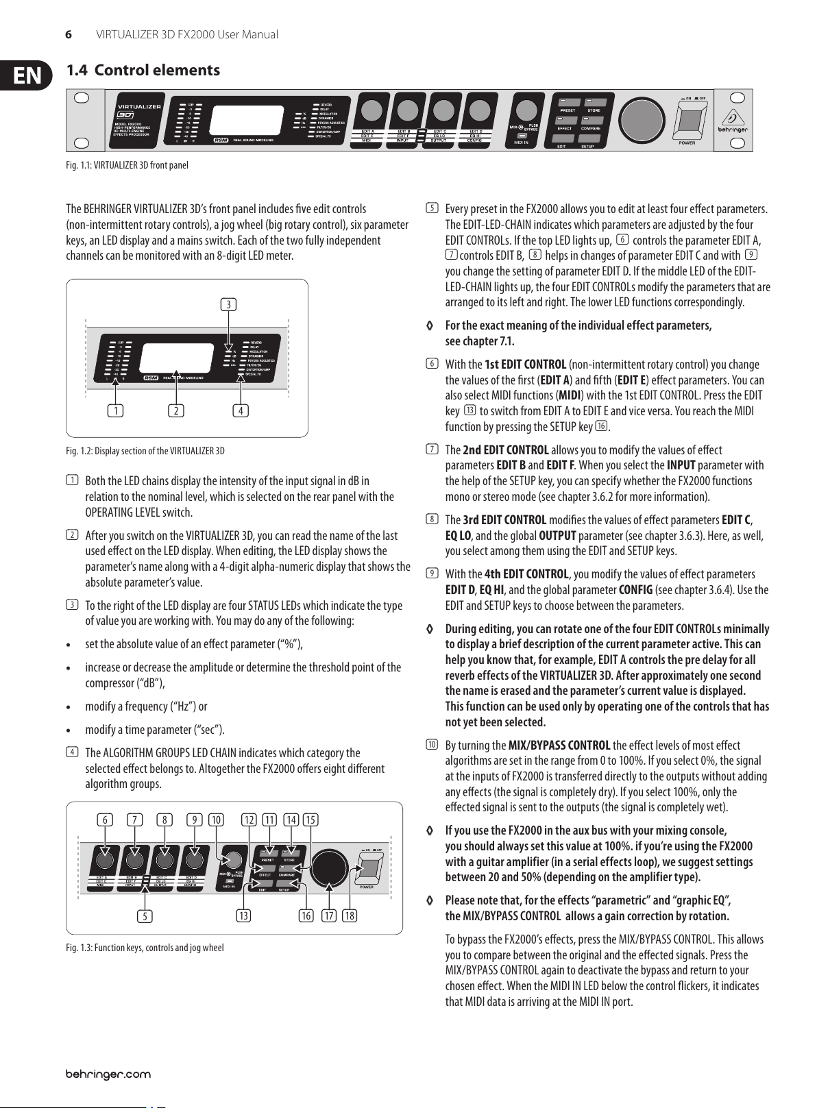
1.4 Control elements
Fig. 1.1: VIRTUALIZER 3D front pan el
The BEHRINGER VIRTUALIZER 3D’s front panel includes ve edit controls
(non-intermittent rotary controls), a jog wheel (big rotary control), six parameter
keys, an LED display and a mains switch. Each of the two fully independent
channels can be monitored with an 8-digit LED meter.
(3)
(1) (2)
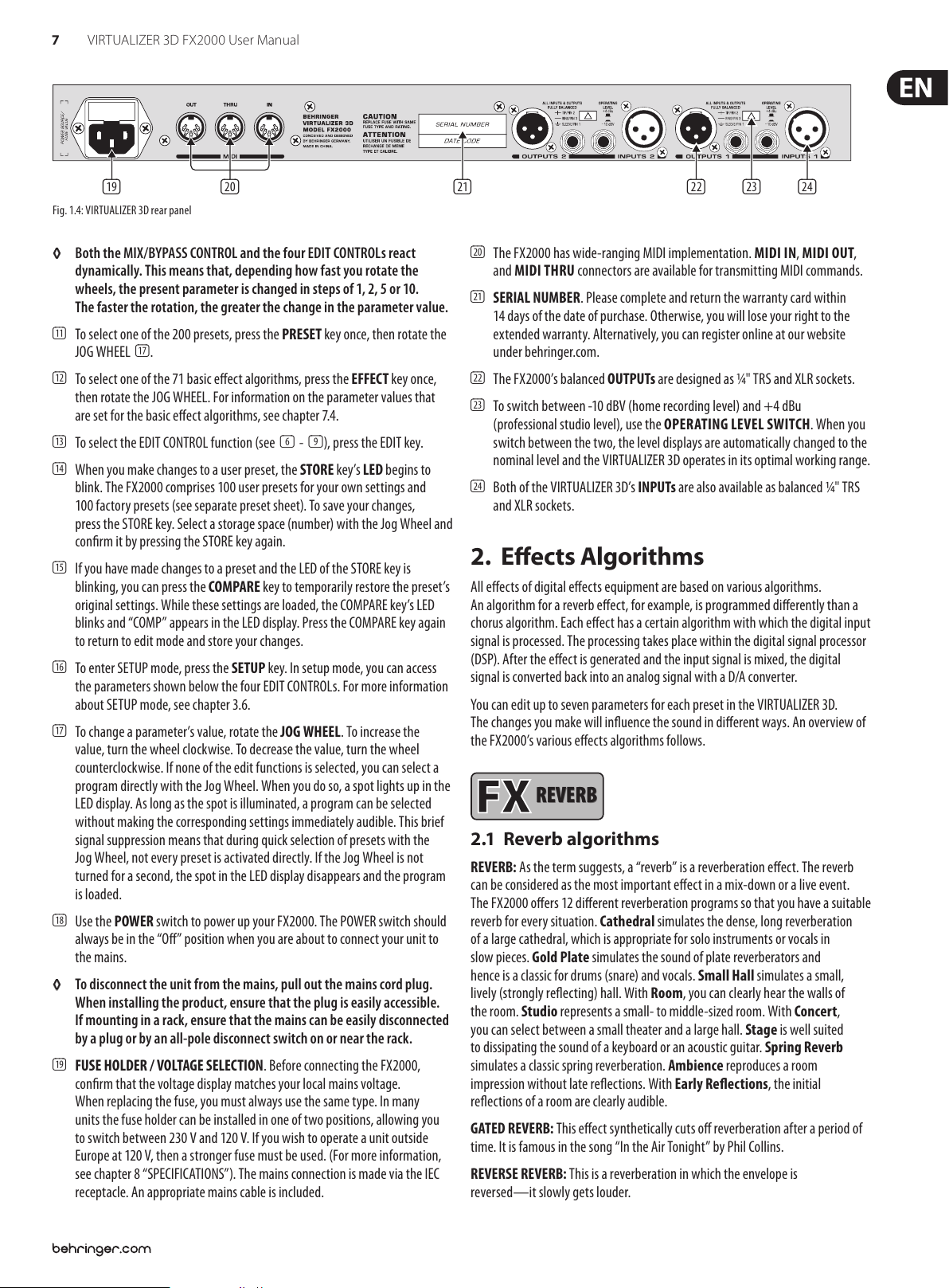
Fig. 1.2: Displa y section of the VI RTUALIZER 3D
(1) Both the LED chains display the intensity of the input signal in dB in
relation to the nominal level, which is selected on the rear panel with the
OPERATINGLEVEL switch.
(2) After you switch on the VIRTUALIZER 3D, you can read the name of the last
used eect on the LED display. When editing, the LED display shows the
parameter’s name along with a 4-digit alpha-numeric display that shows the
absolute parameter’s value.
(3) To the right of the LED display are four STATUS LEDs which indicate the type
of value you are working with. You may do any of the following:
• set the absolute value of an eect parameter (“%”),
• increase or decrease the amplitude or determine the threshold point of the
compressor (“dB”),
• modify a frequency (“Hz”) or
• modify a time parameter (“sec”).
(4) The ALGORITHM GROUPS LED CHAIN indicates which category the
selected eect belongs to. Altogether the FX2000 oers eight dierent
algorithmgroups.
(4)
(6) (7) (8) (9) (10) (11) (14)(12) (15)
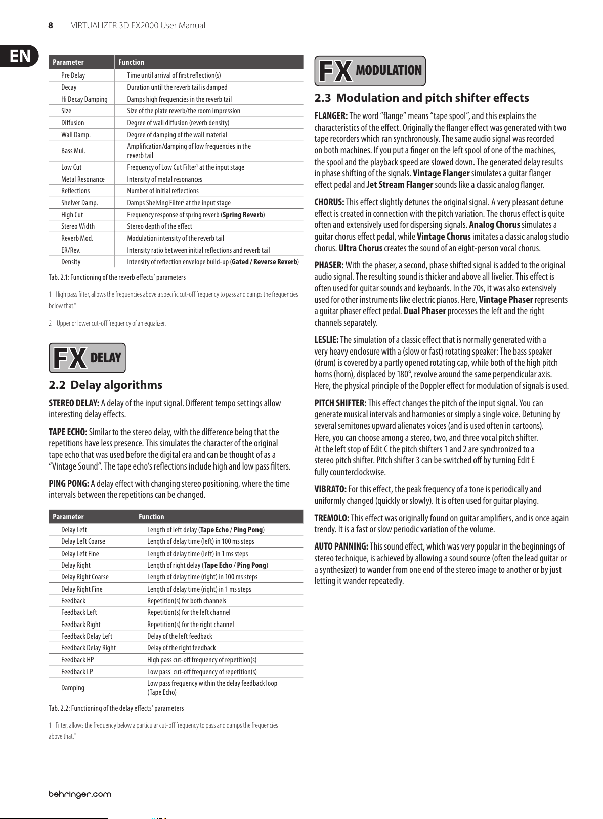
(5) Every preset in the FX2000 allows you to edit at least four eect parameters.
The EDIT-LED-CHAIN indicates which parameters are adjusted by the four
EDIT CONTROLs. If the top LED lights up, (6) controls the parameter EDIT A,
(7) controls EDIT B, (8) helps in changes of parameter EDIT C and with (9)
you change the setting of parameter EDIT D. If the middle LED of the EDIT-
LED-CHAIN lights up, the four EDIT CONTROLs modify the parameters that are
arranged to its left and right. The lower LED functions correspondingly.
◊ For the exact meaning of the individual effect parameters,
see chapter 7.1.
(6) With the 1st EDIT CONTROL (non-intermittent rotary control) you change
the values of the rst (EDIT A) and fth (EDIT E) eect parameters. You can
also select MIDI functions (MIDI) with the 1st EDIT CONTROL. Press the EDIT
key (13) to switch from EDIT A to EDIT E and vice versa. You reach the MIDI
function by pressing the SETUP key (16).
(7) The 2nd EDIT CONTROL allows you to modify the values of eect
parameters EDIT B and EDIT F. When you select the INPUT parameter with
the help of the SETUP key, you can specify whether the FX2000 functions
mono or stereo mode (see chapter 3.6.2 for more information).
(8) The 3rd EDIT CONTROL modies the values of eect parameters EDIT C,
EQLO, and the global OUTPUT parameter (see chapter 3.6.3). Here, as well,
you select among them using the EDIT and SETUP keys.
(9) With the 4th EDIT CONTROL, you modify the values of eect parameters
EDIT D, EQ HI, and the global parameter CONFIG (see chapter 3.6.4). Use the
EDIT and SETUP keys to choose between the parameters.
◊ During editing, you can rotate one of the four EDIT CONTROLs minimally
to display a brief description of the current parameter active. This can
help you know that, for example, EDIT A controls the pre delay for all
reverb effects of the VIRTUALIZER 3D. After approximately one second
the name is erased and the parameter’s current value is displayed.
This function can be used only by operating one of the controls that has
not yet been selected.
(10) By turning the MIX/BYPASS CONTROL the eect levels of most eect
algorithms are set in the range from 0 to 100%. If you select 0%, the signal
at the inputs of FX2000 is transferred directly to the outputs without adding
any eects (the signal is completely dry). If you select 100%, only the
eected signal is sent to the outputs (the signal is completely wet).
◊ If you use the FX2000 in the aux bus with your mixing console,
you should always set this value at 100%. if you’re using the FX2000
with a guitar amplifier (in a serial effects loop), we suggest settings
between 20 and 50% (depending on the amplifier type).
(5)
Fig. 1.3: Functi on keys, controls and j og wheel
(13) (16) (18)(17)
◊ Please note that, for the effects “parametric” and “graphic EQ”,
the MIX/BYPASS CONTROL allows a gain correction by rotation.
To bypass the FX2000’s eects, press the MIX/BYPASS CONTROL. Thisallows
you to compare between the original and the eected signals. Pressthe
MIX/BYPASS CONTROL again to deactivate the bypass and return to your
chosen eect. When the MIDI IN LED below the control ickers, itindicates
that MIDI data is arriving at the MIDI IN port.
Page 7
7 VIRTUALIZER 3D FX2000 User Manual
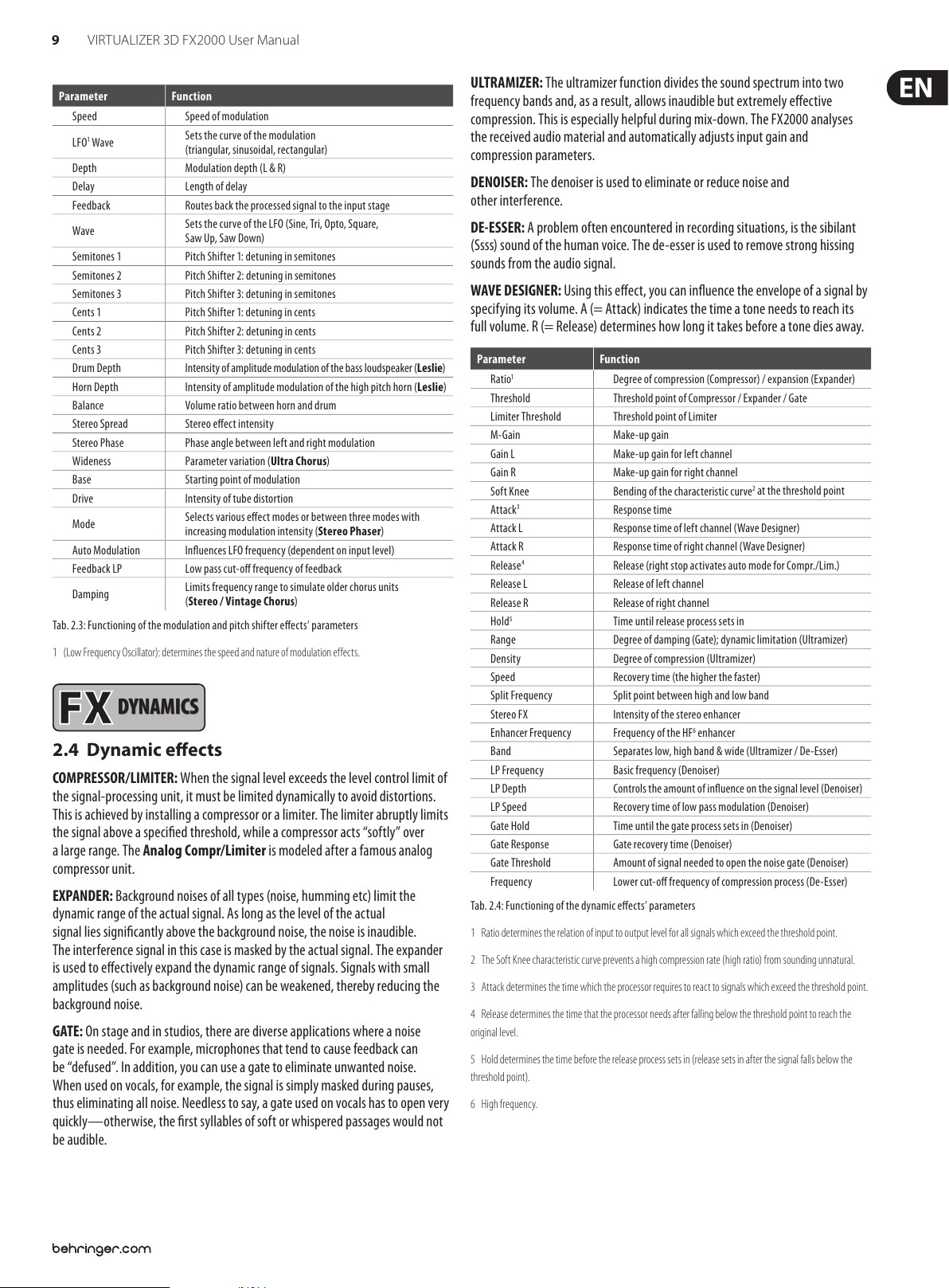
(19) (21) (22) (23) (24)(20)
REVERB
Fig. 1.4: VIRTUALIZER 3D rea r panel
◊ Both the MIX/BYPASS CONTROL and the four EDIT CONTROLs react
dynamically. This means that, depending how fast you rotate the
wheels, the present parameter is changed in steps of 1, 2, 5 or 10.
The faster the rotation, the greater the change in the parameter value.
(11) To select one of the 200 presets, press the PRESET key once, then rotate the
JOG WHEEL (17).
(12) To select one of the 71 basic eect algorithms, press the EFFECT key once,
then rotate the JOG WHEEL. For information on the parameter values that
are set for the basic eect algorithms, see chapter 7.4.
(13) To select the EDIT CONTROL function (see (6) - (9) ), press the EDIT key.
(14) When you make changes to a user preset, the STORE key’s LED begins to
blink. The FX2000 comprises 100 user presets for your own settings and
100factory presets (see separate preset sheet). To save your changes,
pressthe STORE key. Select a storage space (number) with the Jog Wheel and
conrm it by pressing the STORE key again.
(15) If you have made changes to a preset and the LED of the STORE key is
blinking, you can press the COMPARE key to temporarily restore the preset’s
original settings. While these settings are loaded, the COMPARE key’s LED
blinks and “COMP” appears in the LED display. Press the COMPARE key again
to return to edit mode and store your changes.
(16) To enter SETUP mode, press the SETUP key. In setup mode, you can access
the parameters shown below the four EDIT CONTROLs. For more information
about SETUP mode, see chapter 3.6.
(17) To change a parameter’s value, rotate the JOG WHEEL. To increase the
value, turn the wheel clockwise. To decrease the value, turn the wheel
counterclockwise. If none of the edit functions is selected, you can select a
program directly with the Jog Wheel. When you do so, a spot lights up in the
LED display. As long as the spot is illuminated, a program can be selected
without making the corresponding settings immediately audible. This brief
signal suppression means that during quick selection of presets with the
Jog Wheel, not every preset is activated directly. If the Jog Wheel is not
turned for a second, the spot in the LED display disappears and the program
isloaded.
(18) Use the POWER switch to power up your FX2000. The POWER switch should
always be in the “O” position when you are about to connect your unit to
the mains.
◊ To disconnect the unit from the mains, pull out the mains cord plug.
When installing the product, ensure that the plug is easily accessible.
If mounting in a rack, ensure that the mains can be easily disconnected
by a plug or by an all-pole disconnect switch on or near the rack.
(19) FUSE HOLDER / VOLTAGE SELECTION. Before connecting the FX2000,
conrmthat the voltage display matches your local mains voltage.
Whenreplacing the fuse, you must always use the same type. In many
units the fuse holder can be installed in one of two positions, allowing you
to switch between 230 V and 120 V. If you wish to operate a unit outside
Europe at 120V, then a stronger fuse must be used. (For more information,
see chapter 8 “SPECIFICATIONS”). The mains connection is made via the IEC
receptacle. Anappropriate mains cable is included.
(20) The FX2000 has wide-ranging MIDI implementation. MIDI IN, MIDI OUT,
and MIDI THRU connectors are available for transmitting MIDI commands.
(21) SERIAL NUMBER. Please complete and return the warranty card within
14 days of the date of purchase. Otherwise, you will lose your right to the
extended warranty. Alternatively, you can register online at our website
under behringer.com.
(22) The FX2000’s balanced OUTPUTs are designed as ¼" TRS and XLR sockets.
(23) To switch between -10 dBV (home recording level) and +4 dBu
(professionalstudio level), use the OPERATING LEVEL SWITCH. Whenyou
switch between the two, the level displays are automatically changed to the
nominal level and the VIRTUALIZER 3D operates in its optimal workingrange.
(24) Both of the VIRTUALIZER 3D’s INPUTs are also available as balanced ¼" TRS
and XLR sockets.
2. Eects Algorithms
All eects of digital eects equipment are based on various algorithms.
Analgorithm for a reverb eect, for example, is programmed dierently than a
chorus algorithm. Each eect has a cer tain algorithm with which the digital input
signal is processed. The processing takes place within the digital signal processor
(DSP). After the eect is generated and the input signal is mixed, the digital
signal is converted back into an analog signal with a D/A converter.
You can edit up to seven parameters for each preset in the VIRTUALIZER 3D.
Thechanges you make will inuence the sound in dierent ways. An overview of
the FX2000’s various eects algorithms follows.
REVERB
2.1
Reverb algorithms
REVERB: As the term suggests, a “reverb” is a reverberation eect. Thereverb
can be considered as the most important eect in a mix-down or a live event.
TheFX2000 oers 12 dierent reverberation programs so that you have a suitable
reverb for every situation. Cathedral simulates the dense, longreverberation
of a large cathedral, which is appropriate for solo instruments or vocals in
slow pieces. Gold Plate simulates the sound of plate reverberators and
hence is a classic for drums (snare) and vocals. Small Hall simulates a small,
lively(stronglyreec ting) hall. With Room, you can clearly hear the walls of
the room. Studio represents a small- to middle-sized room. WithConcert,
you can select between a small theater and a large hall. Stageis well suited
to dissipating the sound of a keyboard or an acoustic guitar. SpringReverb
simulates a classic spring reverberation. Ambience reproduces a room
impression without late reections. With Early Reections, the initial
reections of a room are clearlyaudible.
GATED REVERB: This eect synthetically cuts o reverberation after a period of
time. It is famous in the song “In the Air Tonight” by Phil Collins.
REVERSE REVERB: This is a reverberation in which the envelope is
reversed—itslowly gets louder.
Page 8
8 VIRTUALIZER 3D FX2000 User Manual
DELAY
MODULATION
Parameter Function
Pre Delay Time unti l arrival of rst r eection(s)
Decay Duration until the reverb tail is damped
Hi Decay Damping Damps high frequencies in the reverb tail
Size Size of the pla te reverb/the room i mpression
Diusion Degree of wall diusion (reverb density)
Wall Damp. Degree o f damping of the wall mate rial
Bass Mul.
Low Cut Frequency of Low Cut Filter
Metal Resonance Intensity of metal resonances
Reections Number of initial reections
Shelver Damp. Damps Shelving Filter
High Cut Frequenc y response of spr ing reverb (Spring Reverb)
Stereo Width Stereo depth of the e ect
Reverb Mod. Modulation intensity of the reverb tail
ER/Rev. Inte nsity ratio bet ween initial re ections and rev erb tail
Density Intensit y of reectio n envelope build- up (Gated / Reverse Reve rb)
Tab. 2.1: Fun ctioning of the r everb eects ’ parameters
1 High pass f ilter, allows the freque ncies above a speci fic cut-off f requency to pa ss and damps the fre quencies
below that."
2 Upper or lower c ut-off fre quency of an equalize r.
Amplication/damping of low frequencies in the
reverb tail
1
at the input s tage
2
at the input s tage
DELAY
2.2
Delay algorithms
MODULATION
2.3
Modulation and pitch shifter eects
FLANGER: The word “ange” means “tape spool”, and this explains the
characteristics of the eect. Originally the anger eect was generated with two
tape recorders which ran synchronously. The same audio signal was recorded
on both machines. If you put a nger on the left spool of one of the machines,
thespool and the playback speed are slowed down. The generated delay results
in phase shifting of the signals. Vintage Flanger simulates a guitar anger
eect pedal and Jet Stream Flanger sounds like a classic analog anger.
CHORUS: This eect slightly detunes the original signal. A very pleasant detune
eect is created in connection with the pitch variation. The chorus eect is quite
often and extensively used for dispersing signals. Analog Chorus simulates a
guitar chorus eect pedal, while Vintage Chorus imitates a classic analog studio
chorus. Ultra Chorus creates the sound of an eight-person vocal chorus.
PHASER: With the phaser, a second, phase shifted signal is added to the original
audio signal. The resulting sound is thicker and above all livelier. This eect is
often used for guitar sounds and keyboards. In the 70s, it was also extensively
used for other instruments like electric pianos. Here, Vintage Phaser represents
a guitar phaser eect pedal. Dual Phaser processes the left and the right
channels separately.
LESLIE: The simulation of a classic eect that is normally generated with a
very heavy enclosure with a (slow or fast) rotating speaker: The bass speaker
(drum) is covered by a partly opened rotating cap, while both of the high pitch
horns (horn), displaced by 180°, revolve around the same perpendicular axis.
Here,thephysical principle of the Doppler eect for modulation of signals is used.
STEREO DELAY: A delay of the input signal. Dierent tempo settings allow
interesting delay eects.
TAPE ECHO: Similar to the stereo delay, with the dierence being that the
repetitions have less presence. This simulates the character of the original
tape echo that was used before the digital era and can be thought of as a
“VintageSound”. The tape echo’s reections include high and low pass lters.
PING PONG: A delay eect with changing stereo positioning, where the time
intervals between the repetitions can be changed.
Parameter Function
Delay Lef t Length of le ft delay (Tape Echo / Ping Pong)
Delay Lef t Coarse Le ngth of delay time (le ft) in 100 ms steps
Delay Left Fine Length of d elay time (left) in 1 ms s teps
Delay Right Length of r ight delay (Tape Echo / Ping Pong)
Delay Right C oarse Length of d elay time (right) in 100 ms ste ps
Delay Right Fine Length of de lay time (right) in 1 ms steps
Feedback Repetition(s) for both channels
Feedback Left Repetit ion(s) for the left ch annel
Feedback Right Repetition(s) for the right channel
Feedback Delay Lef t Del ay of the left fee dback
Feedback Delay Right Delay of the r ight feedback
Feedback HP High pass cut-o frequency of repetition(s)
Feedback LP Low pass
Damping
Tab. 2.2: Functi oning of the delay ee cts’ parame ters
1
cut-o frequency of repetition(s)
Low pass fr equency with in the delay feedba ck loop
(TapeEcho)
PITCH SHIFTER: This eect changes the pitch of the input signal. Youcan
generate musical intervals and harmonies or simply a single voice. Detuningby
several semitones upward alienates voices (and is used often in cartoons).
Here,you can choose among a stereo, two, and three vocal pitch shifter.
At the left stop of Edit C the pitch shifters 1 and 2 are synchronized to a
stereo pitch shifter. Pitch shifter 3 can be switched o by turning Edit E
fullycounterclockwise.
VIBRATO: For this eect, the peak frequency of a tone is periodically and
uniformly changed (quickly or slowly). It is often used for guitar playing.
TREMOLO: This eect was originally found on guitar ampliers, and is once again
trendy. It is a fast or slow periodic variation of the volume.
AUTO PANNING: This sound eect, which was very popular in the beginnings of
stereo technique, is achieved by allowing a sound source (often the lead guitar or
a synthesizer) to wander from one end of the stereo image to another or by just
letting it wander repeatedly.
1 Filter, allows the f requency belo w a particular cu t-off frequ ency to pass and damp s the frequencie s
above that."
Page 9
9 VIRTUALIZER 3D FX2000 User Manual
DYNAMICS
Parameter Function
Speed Speed of mod ulation
1
LFO
Wave
Depth Modul ation depth (L & R)
Delay Length of d elay
Feedback R outes back the pro cessed signal to the i nput stage
Wave
Semitones 1 Pitch Shifter 1: detuning in semitones
Semitones 2 Pitch Shifter 2: detuning in semitones
Semitones 3 Pitch Shifter 3: detuning in semitones
Cents 1 Pitch Shif ter 1: detuning in cents
Cents 2 Pitch Shif ter 2: detuning in cents
Cents 3 Pitch Shif ter 3: detuning in cents
Drum Depth Intensit y of amplitude m odulation of the ba ss loudspeaker (Leslie)
Horn Depth In tensity of amplit ude modulation of t he high pitch horn (Leslie)
Balance Volum e ratio between h orn and drum
Stereo Spread Stereo eect intensity
Stereo Phase Phas e angle between l eft and right mo dulation
Wideness Parameter variation (Ultra Chorus)
Base Starting point of modulation
Drive Intensity of tube distortion
Mode
Auto Modulation Inuences LFO frequency (dependent on input level)
Feedback LP Low pass cut-o frequency of feedback
Damping
Tab. 2.3: Function ing of the modulatio n and pitch shifte r eects’ pa rameters
1 (Low Frequenc y Oscillator): deter mines the speed an d nature of modulation e ffect s.
Sets the c urve of the modul ation
(triangular, sinusoidal, rec tangular)
Sets the c urve of the LFO (Sine, Tri, Op to, Square,
Saw Up, Saw Down)
Selec ts various ee ct modes or bet ween three modes w ith
increasing modulation intensity (Stereo Phaser)
Limits frequency range to simulate older chorus units
(Stereo / Vi ntage Chorus)
DYNAMICS
2.4
Dynamic eects
COMPRESSOR/LIMITER: When the signal level exceeds the level control limit of
the signal-processing unit, it must be limited dynamically to avoid distortions.
This is achieved by installing a compressor or a limiter. The limiter abruptly limits
the signal above a specied threshold, while a compressor ac ts “softly” over
a large range. The Analog Compr/Limiter is modeled after a famous analog
compressor unit.
EXPANDER: Background noises of all types (noise, humming etc) limitthe
dynamic range of the actual signal. As long as the level of the actual
signal lies signicantly above the background noise, the noise is inaudible.
Theinterference signal in this case is masked by the actual signal. The expander
is used to eectively expand the dynamic range of signals. Signals with small
amplitudes (such as background noise) can be weakened, thereby reducing the
backgroundnoise.
GATE: On stage and in studios, there are diverse applications where a noise
gate is needed. For example, microphones that tend to cause feedback can
be “defused”. In addition, you can use a gate to eliminate unwanted noise.
When used on vocals, for example, the signal is simply masked during pauses,
thuseliminating all noise. Needless to say, a gate used on vocals has to open very
quickly—other wise, the rst syllables of soft or whispered passages would not
be audible.
ULTRAMIZER: The ultramizer function divides the sound spectrum into two
frequency bands and, as a result, allows inaudible but extremely eective
compression. This is especially helpful during mix-down. The FX2000 analyses
the received audio material and automatically adjusts input gain and
compression parameters.
DENOISER: The denoiser is used to eliminate or reduce noise and
otherinterference.
DE-ESSER: A problem often encountered in recording situations, is the sibilant
(Ssss) sound of the human voice. The de-esser is used to remove strong hissing
sounds from the audio signal.
WAVE DESIGNER: Using this eect, you can inuence the envelope of a signal by
specifying its volume. A (= Attack) indicates the time a tone needs to reach its
full volume. R (= Release) determines how long it takes before a tone dies away.
Parameter Function
1
Ratio
Threshold Threshold poin t of Compressor / E xpander / Gate
Limiter Threshold Threshold point of Limiter
M-Gain Make-up gain
Gain L Make-up g ain for left chan nel
Gain R M ake-up gain for rig ht channel
Soft Knee Bending of the characteristic curve
3
Attac k
Attac k L Resp onse time of lef t channel (Wave Design er)
Attac k R Re sponse time of righ t channel (Wave Design er)
4
Release
Release L Release of left channel
Release R Release of right channel
5
Hold
Range Degree of damping (Gate); dynamic limitation (Ultramizer)
Density Degree of compression (Ultramizer)
Speed Recovery time (the higher the faster)
Split Frequency Spli t point between h igh and low band
Stereo FX Intensity of the stereo enhancer
Enhancer Frequency Frequenc y of the HF
Band Separat es low, high band & wide (Ultr amizer / De-Ess er)
LP Frequency Basic frequency (Denoiser)
LP Depth Controls the amount of inuence on the signal level (Denoiser)
LP Speed Recovery time of low pass modulation (Denoiser)
Gate Hold Time until the gate process sets in (Denoiser)
Gate Response Gate recovery time (Denoiser)
Gate Threshold Amount of signal needed to open the noise gate (Denoiser)
Frequency Lower c ut-o frequenc y of compressio n process (De-E sser)
Tab. 2.4: Functioni ng of the dynamic ee cts’ parame ters
1 Ratio dete rmines the relatio n of input to output le vel for all signals which e xceed the thresho ld point.
2 The Sof t Knee characte ristic curve p revents a high compre ssion rate (high rat io) from sounding unnat ural.
3 Attack de termines the time w hich the process or requires to reac t to signals which excee d the threshold po int.
4 Release de termines the time t hat the processor n eeds after fa lling below the thresh old point to reach the
original level.
5 Hold deter mines the time bef ore the release proce ss sets in (release s ets in after th e signal falls below the
threshold point).
6 High frequency.
Degree of compression (Compressor) / exp ansion (Expander)
2
at the threshold point
Response time
Release (rig ht stop activat es auto mode for Comp r./ Lim.)
Time unti l release process s ets in
6
enhancer
Page 10

10 VIRTUALIZER 3D FX2000 User Manual
PSYCHO
ACOUSTICS
FILTER/EQ
PSYCHO
ACOUSTICS
2.5
Psycho-acoustic eects
EXCITER: An exciter works with psycho-acoustic principles to add articially
generated overtones to the original signal, thereby increasing its presence and
loudness (the subjective volume impression) without any signicant increase of
the signal level.
ENHANCER: The enhancer works like a dynamic pitch equalizer. Its eectiveness
depends on the associated high frequencies and the intensity of the input signal.
ULTRA BASS: This awesome combination of sub-harmonic processor,
bassexciter, and limiter adds a nal touch to your music production.
STEREO IMAGER: This eect is used to process stereo main signals. The signal is
rst subdivided into middle and side signal (MS Matrix). Both parts can then be
amplied when desired and placed on the stereo image.
ULTRA WIDE: This eect is suitable to pep up speaker systems with an especially
broad stereo image.
BINAURALIZER: The binauralizer also extends the stereo image. Additionally,
itcompensates for inter-channel cross talk of both speakers (left loudspeaker on
right ear and vice versa).
Parameter Function
Gain Gain correction
Frequency Cu t-o frequenc y of the side chain hig h pass lter
Filter Q
Timbre R atio of straight an d unstraight har monics (Exciter)
Harmonics Kick
Mix Controls amount of harmonics (Exciter)
Bass Gain Degree o f the bass enhancer
Sub-bass Frequency Cut-o freque ncy of the sub-b ass low pass lter (Ultra Bass)
Sub-bass Level Degree of sub-harmonics
Harmonics Degree of synthetic harmonics (Excit er)
Harmonics Density Density of harmonics (Ultra Bass)
Bass Gain Degree o f original bass sign al (Ultra Bass)
Spread
Spread Mode Selec ts betwee n two dierent spr ead variations (Stereo Imager)
MS Balance R atio of middle and sid e signal (Stereo Imager)
Stereo Balance Bala nce of stereo signal (Stereo Imager)
Mono Balance Bala nce of mono signal (Stereo Imager)
Center
Xover Frequency Frequency of the crossover lter for the center signal (Ultra Wide)
Space Deg ree of stereo wide ness (Binauralizer)
Mode Sele cts between headphones and speaker operation (Binauralizer)
Speaker Distance Run time / speaker dis tance (Binauralizer)
Speaker Compensation Degree o f crosstalk comp ensation (Binauralizer)
High Frequency Split fre quency of the c rossover lter fo r the side chain (Enhancer)
High Gain Amount of added high frequencies (Enhancer)
Bass Width Charac ter of added bass f requencies (Enhancer)
Mid Q Bandwidth of added mid frequencies (Enhancer)
Mid Gain Amount of added mid frequencies (Enhancer)
Harmon. Freq. Frequency of added bass harmonics (Ultra Bass)
Harmon. Level Amount of adde d bass frequenc ies (Ultra Bass)
Tab. 2.5: Function ing of the psycho- acoustic eec ts’ paramete rs
Resonanc e of the high pass lter (emp hasizes cut-o f requency
for Excit er)
Activa tes an amplicati on of harmonics de pendent on the inpu t
level (Exciter)
Controls the inuence on the stereo signal (Stereo Imager) /
degree of s tereo expansi on (Ultra Wide)
Amount of center impression in the stereo signal
(Ultra Wide / Binauralizer)
1
(Exciter)
FILTER/EQ
2.6
Filter/EQ eects
FILT ER: Filters, in general, inuence the frequency response of a signal. A low
pass lter allows low frequencies to pass and suppresses high frequencies,
whilea high pass lter allows high frequencies to pass and suppresses
lowfrequencies.
PARAMETRIC EQ: The parametric equalizer is the most highly-developed
form of equalization. You can control the three parameters which dene the
so-called gauss equalizer curve: bandwidth, frequency and amplitude boosting
or lowering.
GRAPHIC EQ: Eight lter bands are arranged next to each other for this graphic
equalizer. In contrast to the parametric equalizer, frequency and bandwidth are
pre-determined here.
Parameter Function
Base Frequency Cut-o frequency
Depth Degree of inuence
Resonance Resonance of t he lter
Type O perating mode of the lter
Attac k R esponse time of the e nvelope follower
Release Release ti me of the envelope fo llower
Speed Speed of the L FO
Wave Sets t he curve of the LFO
Gai n 1/2 Boos t/cut (param. EQ)
Fre q. 1/2 Mid f requency (param. EQ)
Q 1/2 Q factor (param. EQ)
200 Hz Boost/cu t at 200 Hz (graph. EQ)
400 Hz Boost/cu t at 400 Hz (graph. EQ)
800 Hz Boost/cu t at 800 Hz (graph. EQ)
1.6 kH z Boos t/cut at 1.6 kHz (graph. EQ)
3.2 kHz Boost/cut a t 3.2 kHz (graph. EQ)
6.4 kHz Boost /c ut at 6.4 kHz (graph. EQ)
Mix Gain correction (Auto Filter / LFO Filter)
Gain
Tab. 2.6: Function ing of the lter/EQ ee cts’ parame ters
Output g ain of the lter block
(parametric / graphic EQ)
1 High pass f ilter, which allows frequ encies above a spec ified cut-of f frequenc y to pass and damps the
frequencies lying below it.
Page 11
11 VIRTUALIZER 3D FX2000 User Manual
DISTORTION/AMP
DISTORTION/AMP
2.7
Distortion eects and amp simulations
VOCAL DISTORTION: This eect is very hip when used on vocals and drum loops,
and is combined with a delay and anger.
TUBE DISTORTION: This eec t simulates the sound of dierent tube types.
Whenan analog tube, as found in a guitar amplier, is overamplied by raising
the input signal (e.g. of a guitar), the original signal is mixed with the harmonic
overtones. With rising overmodulation (also known as saturation of tubes),
theoriginal signal is distor ted and the sound is fresh and full. This is a classic
sound in rock music.
GUITAR AMP: This eect simulates the sound characteristics of a complete guitar
amplier. You can connect a guitar or bass (after appropriate pre-amplication)
directly to the VIRTUALIZER 3D, and from there to a mixing console or
recordingdevice.
TRI FUZZ: This is a special guitar distortion type. Jimi Hendrix was one of the rst
guitarists to recognize the appeal of this broadband transistor overmodulation.
Thehumming distortion of the FUZZ BOX has again become popular with
alternative rock and grunge. The VIRTUALIZER 3D’s fuzz works in three dierent
frequency bands.
SPEAKER SIMULATION: The VIRTUALIZER 3D is able to simulate various types of
speakers. Typical guitar amplif ying speakers as well as multimedia speakers are
available. You can also use a parametric equalizer to further rene the sound.
RING MODULATOR: This eect allows a radical alienation of audio signals.
Similar to the principle of FM radio, the signal is multiplied by a carrier frequency,
so that frequency modulation (FM) takes place. This eect is very well suited for
vocal alienation (robot voice).
LO-FI: For years, digital technique has been striving for high quality, lownoise,
andbrilliant sounds. In the recent past there have been increasing calls for a
return “tothe roots” to achieve the warmth of the old analog sounds. Thetechno/
dance group swears by vinyl and some music lovers miss the charm of good old
vinyl discs and tape machines. This trend is known as Lo-Fi (instead of Hi-Fi).
We have taken this tendency into account and included the relevant eect in
the FX2000. Your recordings sound like 8-bit audio, complete with noise and
humming like the old days! A true drum loop in TR808/TR909 style really gets
going when it sounds thick and dusty.
Parameter Function
Gain Volu me
Distortion Distortion
Drive
Type
Delay Length of d elay
Delay Gain Degree of delay
Flanger Level Degre e of anger
Flanger Speed Speed of a nger
Pre HP Frequency of the in-series connected high pass lter
Pre LP Frequency of the in-series connected low pass lter
Tube Selection Selects between three tube types
Mid EQ Mid equalizer
In Gain Input gain
Low Fuzz Distor tion of low fr equencies
Mid Fuzz Distortion of mid frequencies
Hi Fuzz Distortion of high frequencies
Cabinet Type Selec ts between eig ht speaker types
Presence Pres ence
Hi Damp Damping of high frequency parts
EQ Gain Raising or lowering of EQ
EQ Frequency Frequ ency of EQ
EQ Q Q fac tor of EQ
Speed Speed of LFO
Depth Modulation depth
Carrier Frequency Modulation frequency
Mode
Slewing
Bit Resolution R esolution of D/A convert er
Buzz Leve l Intensity o f the buzz level
Noise Gain Volume of the noise
Noise HP Lower cut-o frequency of the noise
Noise LP Upper cut-o frequency of the noise
Damp Frequenc y of low pass lter a fter the tube s tage (Tube Distortion)
Tone
Tab. 2.7: Parameter fun ctions of disto rtion eec ts and amplica tion simulations
Degree of tube distortion (Tube Distortion & Guitar Amp) /
distor tion at the outpu t circuitry ( Tri Fuz z)
Nature of vo cal distorti on (Vocal Distortion) / selection o f eight
dierent loudspeakers
(Speaker Simulation)
(Ring Modulator): LFO = The LFO modulate s.
ENV=Modulat ion through envelo pe follower.
RAND = Modulation through random generator.
SINE = The inpu t signal is replaced by a si ne tone and modulate d
by a random ge nerator.
Smoothin g of modulation sign al for RAND and SINE
(Ring Modulator)
High frequency attenuation of input signal
(Ring Mod ulator / LoFi)
Page 12

12 VIRTUALIZER 3D FX2000 User Manual
SPECIAL
FX
SERIAL
SPECIAL
FX
2.8
Special eects
VINYLIZER: This eect adds clicks and/or noise to your audio signal,
simulatingold vinyl records and tape recorders.
SAMPLER: This sampler allows you to record up to ve seconds of program
material. Use Edit A for recording and Edit B for playback of the sampled material.
◊ To clear the contents of the sampler, select a different effect.
VOCODER: The vocoder, an old acquaintance, has become popular again due to
the disco renaissance (hear it in “Around the World” by Daft Punk or “California”
by 2Pac). A control signal (usually a voice) is used in the right channel to modulate
another signal which lies on the left channel (usually a synthesizer sound).
Itsounds as if the synthesizer is talking (robot voice).
VOICE CANCELER: The voice canceler is a very eective Karaoke eect. It allows
removal of mono vocal parts in stereo recordings. The bass part, however,
remains untouched.
RESONATOR: A resonator simulates an oscillating system that amplies a specic
frequency. The resonator implemented here has a resonance frequency that can
be modulated with positive and negative feedbacks of up to 100%.
Parameter Function
Speed
Clicks Level Volume of clic ks
Scratch Level Volume of "crack s in the record"
Noise Level Volume of noise
Noise Frequency Frequency response of noise
Record / Stop St art / stop recor ding
Play / Stop Star t / stop playback
Mode
Sensitivity Modulation intensity / input sensitivity
Attac k R esponse time of enve lope follower
Release Release time of envelope follower
Bass Frequency Upper cut-o f requency of ba ss frequencie s that are not eec ted
MS Balance De gree of mid elimination
Treb le Pa n Panorama of high frequencies
Gain Gain correction
Depth Modulation depth
Carrier Frequency Modulation frequency
Feedback Degree of feedback
Slewing (Resonato r): Sm oothing of modulat ion signal for RAND a nd SINE
Tone Frequency spec trum of input signal (Vinylizer)
Tab. 2.8: Paramete r functions of sp ecial eect s
Rotatio ns per minute (Vinyl izer) / playback spee d (Sampler) /
speed of LF O (resonator)
Forwar d, backward play back, number of re petitions (Sampl er) /
Resonator: LFO modulates (LFO), modulation through envelope
follower (ENV), modulation through random generator (RAND)
SERIAL
2.9
Eects algorithm combinations
(multi-eects programs)
Eects 61 to 71 are multi-eects algorithms, which allow dierent eects to be
used simultaneously. Eect 61, for example, can make a solo guitar “wider” with
chorus and simultaneously add a room reverb. Please note that you can modify
the structure of a multi-eect (see chapters 3.1 and 3.6.4).
CHORUS & REVERB: This algorithm combines the popular chorus with a gold
plate eect (as in algorithm 2).
FLANGER & REVERB: The combination of anger and reverb eects.
LESLIE & REVERB: The input signal, modulated to a degree that you specify,
is then processed with a reverb eect. This eect works especially well with
keyboards and guitars.
PITCH & REVERB: The pitch shifter can be detuned in semitone or cent steps.
The reverb, on the other hand, can be controlled in time and mixing ratio.
DELAY & REVERB: Delay and reverb are the most common combinations for
vocals, solo guitars, etc. The reverb used here is a gold plate, a room that features
a distinctive brilliance and can be used in many ways.
TREMOLO & REVERB: The intensive variation in volume of the tremolo gains
more depth and wideness with the reverb.
PHASER & REVERB: The combination of a classic stereo phaser and a
reverbeect.
CHORUS & DELAY: While the chorus can contribute to a wideness of the signal,
interesting repetition eects can be adjusted with the delay. Vocals can be given
a distinctive eect without making the voice sounding blurred.
FLANGER & DELAY: This eect is just right for creating a modern,
slightly “spacey” vocal sound.
PITCH & DELAY: A repetition of the audio signal, with an oscillatory eect added
by the pitch shifter.
TREMOLO & DELAY: A fast or slow, intensive variation of volume, which is
additionally processed with a panorama eect.
Parameter Func tion
Speed Modulation speed
Reverb Mix
Decay Room size / duratio n of reverb tail
Depth Intensit y of delay, amplitude, or ph ase modulation
Doppler Intensit y of Doppler eec t
Type
Dela y (Time) Length of t he delay
Delay Mix (Choru s & Delay): Ratio of chorus a nd delay
Feedback Degree of feedback
Semitones Detuning in semitones
Cents Det uning in cents
Auto Mod. Inuence on LFO frequency (dependent on the input level)
Hi Damp Damps the high frequencies of the reverb programs
High Cut Frequenc y range of the inpu t signal (Pitch Shif ter & Reverb)
Tab. 2.9: Parameter f unctions of mul ti-eect s programs
Wet/dry mi x of modulation, delay a nd reverb eec ts
(for algori thms 61 - 67)
(Delay & Rever b): Se lects among mo no, stereo and ping po ng delay or
a lter in the f eedback chain
◊ For an overview of the parameters available in the individual programs
refer to chapter 7.1.
Page 13

13 VIRTUALIZER 3D FX2000 User Manual
3. Operation
3.1 Eects structure
Algorithm No.
1-6, 8, 9
7
10
11, 12
Eects structure
IN
L
+
R
IN
L
+
R
IN
L
+
R
IN
L
+
R
PREDELAY FILTER REVERB
PREDELAY FILTER ER REVERB
PREDELAY REVERB
PREDELAY FILTER REVERB
GATE/
RVS
OUT
L
R
OUT
M
L
I
X
E
R
R
OUT
L
R
OUT
L
R
13
14
15
17-19, 21, 24, 26
Fig. 3.1: Eects str ucture, par t 1
IN
L
R
IN
L
R
IN
L
R
IN
L
R
+
+
+
+
+
+
+
DELAY_L
DELAY_R
DELAY_L
DELAY_R
DELAY_L
LP/HP
LP/HP
DELAY_R
FEEDBACK_DEL_L
FEEDBACK_DEL_R
EFFECT
OUT
L
R
OUT
L
R
OUT
L
R
OUT
L
R
Page 14

14 VIRTUALIZER 3D FX2000 User Manual
Algorithm No.
16, 20, 22, 23, 25,
28-30, 38-40,
45-48, 50, 53,
54, 57, 60
27
31-34
35
Eects structure
IN
L
R
IN
L
+
R
IN
L
+
R
IN
L
HP
+
DYNAMICS
HP
R
+
+
PITCH_1
PITCH_2
PITCH_3
DYNAMICS
LP
LP
EFFECT_L
EFFECT_R
+
DYNAMICS
E
N
H
A
N
C
E
R
OUT
L
R
OUT
L
M
I
X
E
R
R
OUT
L
R
OUT
L
L
I
M
I
T
E
R
R
36
37
41
42-44, 59
Fig. 3.2: Ee cts struc ture, part 2
IN
L
+
R
IN
L
+
R
IN
L
+
R
IN
L
R
DYNAMICS
DYNAMICS
BASS ENHANCER
SUBBASS
BASS ENHANCER
FILTER
FILTER
FILTER
FILTER
+
+
EFFECT
OUT
L
G
A
T
E
R
OUT
L
R
OUT
L
R
OUT
L
R
Page 15
15 VIRTUALIZER 3D FX2000 User Manual
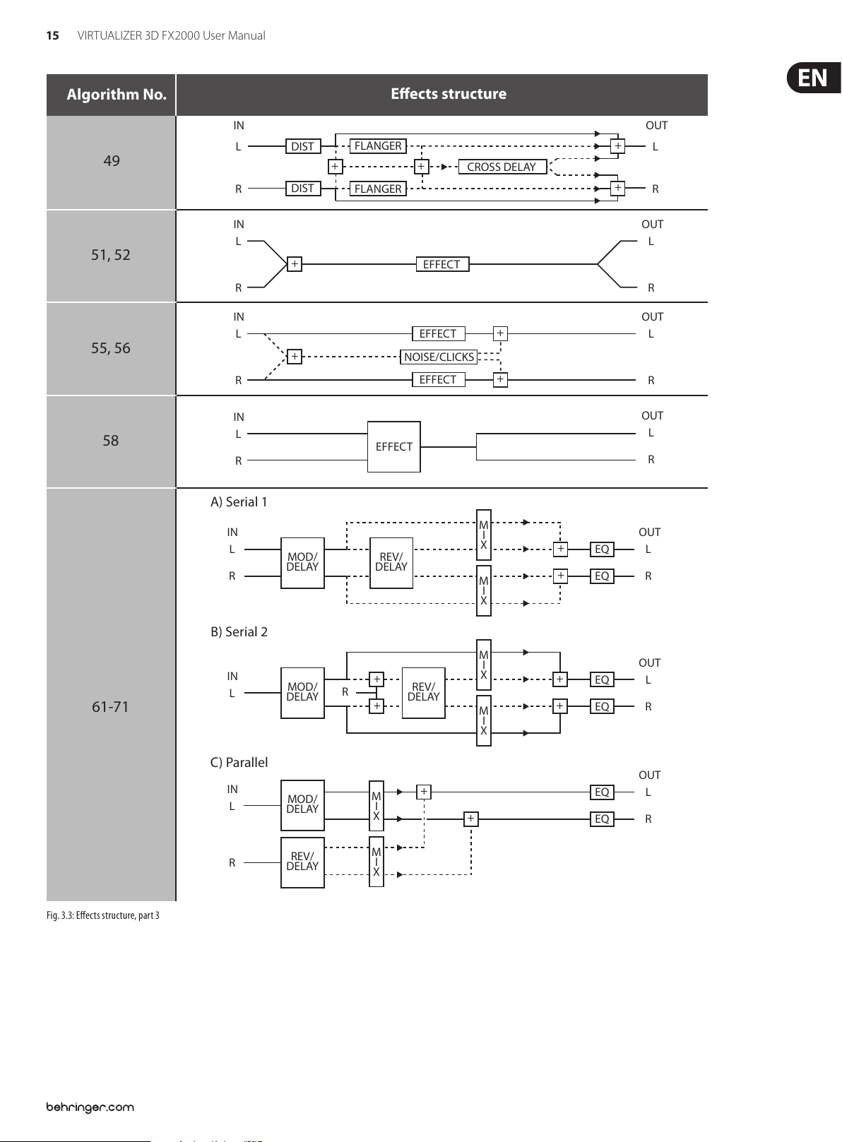
Algorithm No.
49
51, 52
55, 56
58
IN
L
R
IN
L
R
IN
L
R
IN
L
R
A) Serial 1
IN
L
R
DIST
DIST
+
+
MOD/
DELAY
Eects structure
FLANGER
+ +
FLANGER
NOISE/CLICKS
EFFECT
REV/
DELAY
EFFECT
EFFECT
EFFECT
CROSS DELAY
+
+
M
I
X
M
I
X
OUT
+
L
+
R
OUT
L
R
OUT
L
R
OUT
L
R
OUT
+
EQ
+
EQ
L
R
61-71
Fig. 3.3: Eec ts structu re, part 3
B) Serial 2
IN
L
C) Parallel
IN
L
R
MOD/
DELAY
MOD/
DELAY
REV/
DELAY
M
I
+
R
REV/
DELAY
+
M
I
X
M
I
X
+
X
M
I
X
+
+
EQ
+
EQ
EQ
EQ
OUT
L
R
OUT
L
R
Page 16

16 VIRTUALIZER 3D FX2000 User Manual
3.2 Calling up presets
The VIRTUALIZER 3D has 100 internal presets and 100 user presets that can be
overwritten. The two memory banks are located one after another. The internal
presets (I.000 - I.100) come rst and the user presets (U.000 - U.100)follow.
After switching on the unit, the last used preset is automatically restored.
Tochoose a dierent preset, press the PRESET key, then rotate the Jog Wheel.
Tosee the presets in ascending order, rotate the wheel clockwise. To see the
presets in descending order, rotate it counterclockwise.
◊ Please note that it takes the VIRTUALIZER 3D about one second to
activate each newly selected preset. The activation process is indicated
by a blinking light on the display. After the new effect’s data is
loaded, the VIRTUALIZER 3D activates the preset and the light fades.
This brief signal suppression means that during quick selection of
presets with the Jog Wheel, not every preset is activated directly.
Otherwise, there could be partial “shreds” of various presets at the
audio outputs of the FX2000. The VIRTUALIZER 3D gives you the security
that unwanted programs are not loaded. In addition, you can quickly
turn the Jog Wheel and still have enough time to specifically select a
preset without activating “neighboring programs”.
◊ Please note that various ef fects algorithms may have dif ferent volume
levels. Reduce the volume of your monitors while selecting new presets
to prevent sudden changes in volume.
3.3 Editing programs (Edit Mode)
◊ If you make changes in a preset and press the STORE key twice, all of
the preset’s original settings are overwritten and your new parameters
are stored. If you want to retain the old preset, you must select another
preset (using the Jog Wheel) before pressing the STORE key for the
second time.
3.5 Comparing an edited preset with
the corresponding factory preset
(comparefunction)
When you have made changes in a preset but have not yet stored your changes,
the COMPARE Function allows you to load the original factory preset and compare
it with your changes. To do so, press the COMPARE key while in edit mode. As long
as the COMPARE key’s LED blinks, further editing is (temporarily) not possible.
Press the COMPARE key again to return to your edited preset. Here, you have
the choice to either store your changes (see chapter 3.4), or continue editing
(seechapter 3.3).
3.6 SETUP mode
In SETUP mode, you can make global adjustments to the VIRTUALIZER 3D as
described in the sub-sections below. Among these are MIDI, Input mode,
Outputmode and dual engine conguration (CONFIG). To enter SETUP mode,
pressthe SETUP key. The red LED below the EDIT CONTROLs lights up. The four
EDIT CONTROLs can now be used to adjust the SETUP parameters. To exit this
mode, press the SETUP key again.
Programs can be edited easily and quickly with the FX2000. The list on the right
side of the LED DISPLAY gives you an overview of the eects algorithms that the
VIRTUALIZER 3D can generate. To select these basic algorithms, press the EFFECT
key and rotate the Jog Wheel.
By turning the EDIT CONTROLs and the MIX/BYPASS CONTROL, you can extensively
modify the sound of an eects program. You select the EDIT CONTROL function
using the EDIT key. By repeatedly pressing the EDIT key, you can (for example)
specify whether parameter EDIT A or EDIT E will be changed with the 1st EDIT
CONTROL.The currently illuminated LED indicates which parameters will be
edited. By modif ying the EQ LO and EQ HI parameters, you can put the nal touch
on an eect. As soon as you start editing, the LED of the PRESET or EFFECT key
(depending on whether you have already loaded one of the 200 presets or have
selected one of the basic algorithms) dies out. Simultaneously, the LED of the
STORE key starts to blink, indicating that changes have been made.
3.4 Storing programs
To store changes to one of the 100 user presets, as described in chapter 3.3,
youuse the STORE key. All changes to the FX2000’s parameters can be stored
when the STORE key’s LED blinks. For your changes to be accepted, you must
press the STORE key twice. An example:
• You call up a program and make changes to it using the four EDIT
CONTROLs and the MIX/BYPASS CONTROL. Each EDIT CONTROL controls
two parameters that can be selected by pressing the EDIT key. During this
process, theSTORE key blinks, indicating that the preset’s settings have
been changed. However, your changes are not yet stored. If you want to
overwrite the original preset, simply press the STORE key twice to store your
changes. Ifyou wish to retain the original preset, press the STORE key once.
Thedisplay shows the current preset number and star ts blinking. Use the Jog
Wheel to select another preset, which you will overwrite. Press the STORE
key again and your changes are stored in the selected preset.
◊ If there is no input for about five seconds after pressing the STORE key,
the unit goes back to edit mode.
3. 6.1 MIDI control
The FX2000’s MIDI editing options are shown on seven pages. Enter SETUP mode
(see chapter 3.6). With the help of the 1st EDIT CONTROL, you can select seven
dierent MIDI functions. Data input is always carried out with the JOG WHEEL.
the following pages can be selected:
• CHAN: You can set the MIDI channel on the rst page. With the Jog Wheel,
the channel can be set from 01 to 16. If you select “OFF”, the MIDI function is
switched o.
• OMNI: The second page gives access to omni mode. In this case, the unit
receives MIDI data on all 16 MIDI channels. “ON” appears in the display.
Withthe Jog Wheel, select “OFF” to deactivate omni mode.
• CONT: On the third page, you can congure the controller commands.
Youcan choose between four controller modes:
Display Mod e
OFF No controlle r data are transmit ted / received.
RECV C ontroller data are r eceived but not tr ansmitted.
SEND Contr oller data are trans mitted but not re ceived.
BOTH Contr oller data are transmitted and received.
Tab. 3.1: Cont roller settin gs
For controller functions see table 7.4 in chapter 7 “Appendix”.
• PRGM: Page four will bring you to the setup for the program changes.
Onceagain, you have four modes to selec t from:
Display Mod e
OFF Program Cha nges are not transmi tted / received .
RECV P rogram Changes ar e received but not tr ansmitted.
SEND Progr am Changes are tran smitted but not r eceived.
BOTH Pro gram Changes are transmitted and received.
Tab. 3.2: Program c hange settings
Page 17
17 VIRTUALIZER 3D FX2000 User Manual
• STOR: On the fth page, you can select the Store Enable mode. In the “ON”
mode, the VIRTUALIZER 3D receives controller 112 as the direct storage
command—the current settings are stored on the program location
corresponding to the controller value without waiting for a conrmation.
Inthe “OFF” mode, controller 112 is ignored.
◊ CAUTION: The Store Enable mode is aimed to transfer several
presets at once from an external PC to the VIRTUALIZER 3D (see also
chapter 5.1). In this mode, you can very easily overwrite your program
locations by unintentionally sending controller 112 values to the
FX2000! Therefore, we strongly recommend to switch off this mode
immediately after use. When the FX2000 is switched on, this mode is
automatically set to off (“OFF”).
• DUMP: Select the System Exclusive mode (“SysEx”) using the sixth page.
In this mode, the FX2000 is ready to “dump” its complete storage content,
including all settings, to a MIDI sequencer. Start your MIDI sequencer and
turn the JOG WHEEL. The data transfer is indicated by “GO”.
• DR.EN: In this mode, the FX2000 can receive SysEx data from another MIDI
device. To load this data, turn the JOG WHEEL slightly so that the display
blinks. Start your sequencer, and all of your settings, including preset
parameter settings, are received by your VIRTUALIZER 3D. Data transfer
is interrupted by turning the JOG WHEEL slightly so that “----” appears in
thedisplay.
◊ During a SysEx data transfer, all audio functions of the VIRTUALIZER 3D
are inactive.
3.7 Restoring the factory presets
To restore the FX2000 to its preset factory state, press and hold the STORE and
PRESET keys while switching on the unit. “INIT” appears in the DISPLAY and
counting takes place from R 1 to R 100.
◊ This overwrites all changes you have made and restores the
factory presets!
4. Applications
The BEHRINGER VIRTUALIZER 3D is a exible unit that can be used in various
applications. Prior to a presentation of the FX2000’s many uses, please note the
following remarks on how to set signal levels correctly.
4.1 Level setting
Take care to set all levels properly on the FX2000! Low levels deteriorate the
dynamics of the music signal, which results in a poor, weak and noisy sound.
Onthe other hand, excess levels overdriving the converters in the VIRTUALIZER 3D
should also be avoided. Digital distortion is (unlike its analog counterpart)
extremely unpleasant, since it does not occur gradually butabruptly.
Please use the OPERATING LEVEL switch and the input level meter of the FX2000.
Make sure that the Clip LEDs ickers only rarely. Ensure that they never light up
all the time!
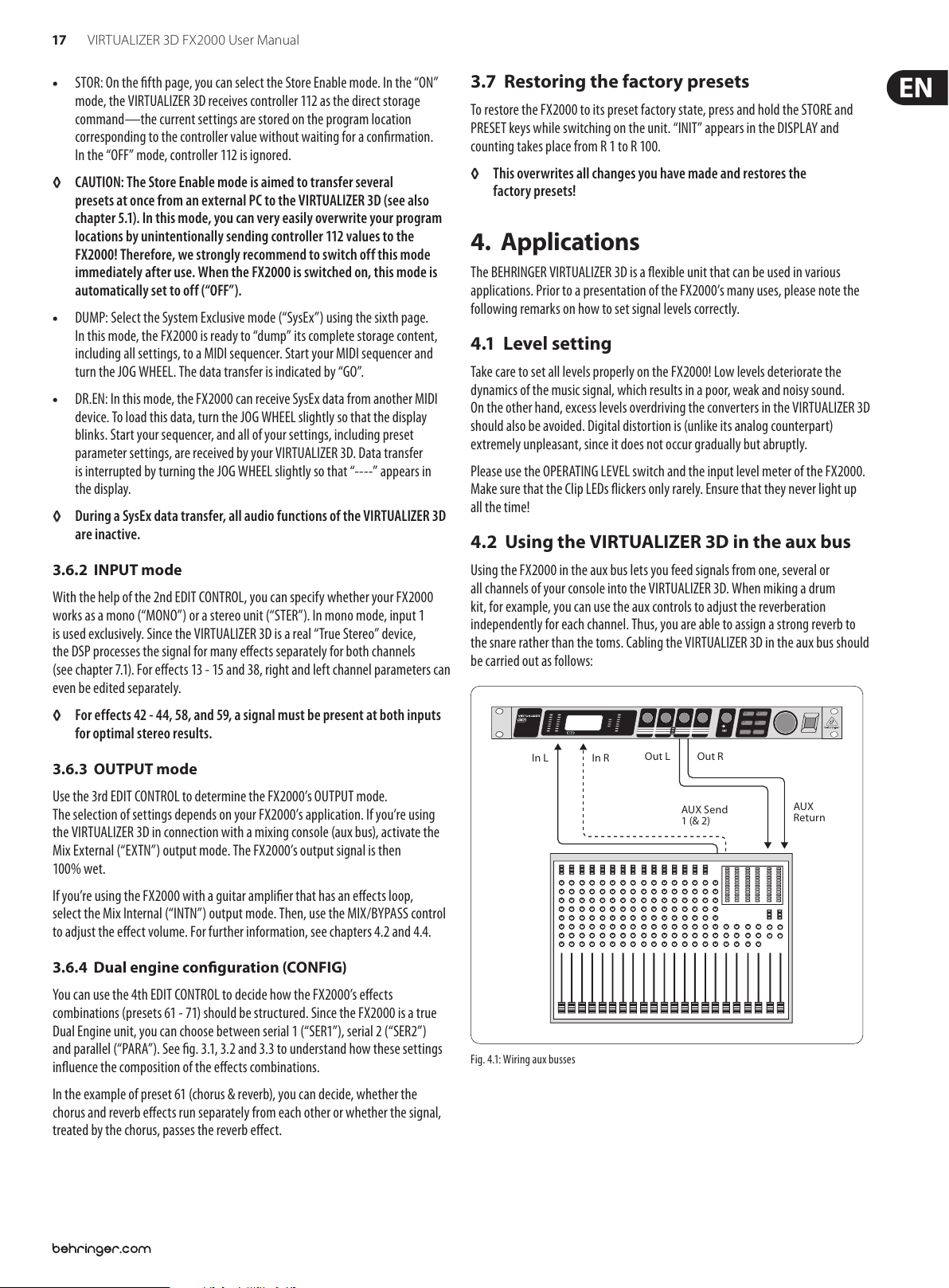
4.2 Using the VIRTUALIZER 3D in the aux bus
3.6.2 INPUT mode
With the help of the 2nd EDIT CONTROL, you can specify whether your FX2000
works as a mono (“MONO”) or a stereo unit (“STER”). In mono mode, input 1
is used exclusively. Since the VIRTUALIZER 3D is a real “True Stereo” device,
the DSP processes the signal for many eects separately for both channels
(seechapter7.1). For eects 13 - 15 and 38, right and left channel parameters can
even be edited separately.
◊ For effects 42 - 44, 58, and 59, a signal must be present at both inputs
for optimal stereo results.
3.6.3 OUTPUT mode
Use the 3rd EDIT CONTROL to determine the FX2000’s OUTPUT mode.
Theselection of settings depends on your FX2000’s application. If you’re using
the VIRTUALIZER 3D in connection with a mixing console (aux bus), activatethe
Mix External (“EXTN”) output mode. The FX2000’s output signal is then
100%wet.
If you’re using the FX2000 with a guitar amplier that has an eects loop,
selectthe Mix Internal (“INTN”) output mode. Then, use the MIX/BYPASS control
to adjust the eect volume. For further information, see chapters 4.2 and 4.4.
3.6.4 Dual engine conguration (CONFIG)
You can use the 4th EDIT CONTROL to decide how the FX2000’s eects
combinations (presets 61 - 71) should be structured. Since the FX2000 is a true
Dual Engine unit, you can choose between serial 1 (“SER1”), serial 2 (“SER2”)
and parallel (“PARA”). See g. 3.1, 3.2 and 3.3 to understand how these settings
inuence the composition of the eects combinations.
Using the FX2000 in the aux bus lets you feed signals from one, several or
all channels of your console into the VIRTUALIZER 3D. When miking a drum
kit, forexample, you can use the aux controls to adjust the reverberation
independently for each channel. Thus, you are able to assign a strong reverb to
the snare rather than the toms. Cabling the VIRTUALIZER 3D in the aux bus should
be carried out as follows:
In L In R
Fig. 4.1: Wiring aux busses
Out L Out R
AUX Send
1 (& 2)
AUX
Return
In the example of preset 61 (chorus & reverb), you can decide, whether the
chorus and reverb eects run separately from each other or whether the signal,
treatedby the chorus, passes the reverb eect.
Page 18
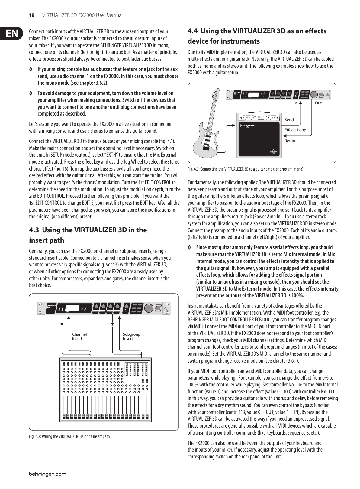
18 VIRTUALIZER 3D FX2000 User Manual
Connect both inputs of the VIRTUALIZER 3D to the aux send outputs of your
mixer. The FX2000’s output socket is connected to the aux return inputs of
your mixer. Ifyou want to operate the BEHRINGER VIRTUALIZER 3D in mono,
connect one of its channels (left or right) to an aux bus. As a matter of principle,
eectsprocessors should always be connected to post fader aux busses.
◊ If your mixing console has aux busses that feature one jack for the aux
send, use audio channel 1 on the FX2000. In this case, you must choose
the mono mode (see chapter 3.6.2).
◊ To avoid damage to your equipment, turn down the volume level on
your amplifier when making connections. Switch off the devices that
you want to connect to one another until plug connections have been
completed as described.
Let’s assume you want to operate the FX2000 in a live situation in connection
with a mixing console, and use a chorus to enhance the guitar sound.
Connect the VIRTUALIZER 3D to the aux busses of your mixing console (g. 4.1).
Make the mains connection and set the operating level if necessary. Switch on
the unit. In SETUP mode (output), select “EXTN” to ensure that the Mix External
mode is activated. Press the eect key and use the Jog Wheel to selec t the stereo
chorus eect (no. 16). Turn up the aux busses slowly till you have mixed the
desired eect with the guitar signal. After this, you can start ne tuning. Youwill
probably want to specify the chorus’ modulation. Turn the 1st EDIT CONTROL to
determine the speed of the modulation. To adjust the modulation depth, turnthe
2nd EDIT CONTROL. Proceed further following this principle. Ifyou want the
1stEDIT CONTROL to change EDIT E, you must rst press the EDIT key. After all the
parameters have been changed as you wish, you can store the modications in
the original (or a dierent) preset.
4.3 Using the VIRTUALIZER 3D in the
insertpath
Generally, you can use the FX2000 on channel or subgroup inserts, using a
standard insert cable. Connection to a channel insert makes sense when you
want to process very specic signals (e.g. vocals) with the VIRTUALIZER3D,
orwhen all other options for connecting the FX2000 are already used by
other units. For compressors, expanders and gates, the channel insert is the
bestchoice.
4.4 Using the VIRTUALIZER 3D as an eects
device for instruments
Due to its MIDI implementation, the VIRTUALIZER 3D can also be used as
multi-eec ts unit in a guitar rack. Naturally, the VIRTUALIZER 3D can be cabled
both as mono and as stereo unit. The following examples show how to use the
FX2000 with a guitar setup.
In
Send
Effects Loop
Return
Fig. 4.3: Connecting the VIRTUALIZER 3D to a guitar amp (send/return mono)
Fundamentally, the following applies: The VIRTUALIZER 3D should be connected
between preamp and output stage of your amplier. For this purpose, most of
the guitar ampliers oer an eects loop, which allows the preamp signal of
your amplier to pass on to the audio input stage of the FX2000. Then, in the
VIRTUALIZER 3D, the preamp signal is processed and sent back to its amplier
through the amplier’s return jack (Power Amp In). If you use a stereo rack
system for amplication, you can also set up the VIRTUALIZER 3D in stereo mode.
Connect the preamp to the audio inputs of the FX2000. Each of its audio outputs
(left/right) is connected to a channel (lef t/right) of your amplier.
◊ Since most guitar amps only feature a serial effects loop, you should
make sure that the VIRTUALIZER 3D is set to Mix Internal mode. In Mix
Internal mode, you can control the effects intensity that is applied to
the guitar signal. If, however, your amp is equipped with a parallel
effects loop, which allows for adding the effects signal portion
(similar to an aux bus in a mixing console), then you should set the
VIRTUALIZER 3D to Mix External mode. In this case, the effects intensity
present at the outputs of the VIRTUALIZER 3D is 100%.
Out
Channel
Insert
Fig. 4.2: Wiring the VIRTUALIZER 3D in the insert path
Subgroup
Insert
Instrumentalists can benet from a variety of advantages oered by the
VIRTUALIZER 3D‘s MIDI implementation. With a MIDI foot controller, e.g. the
BEHRINGER MIDI FOOT CONTROLLER FCB1010, you can transfer program changes
via MIDI. Connect the MIDI out port of your foot controller to the MIDI IN port
of the VIRTUALIZER 3D. If the FX2000 does not respond to your foot controller’s
program changes, check your MIDI channel settings. Determine which MIDI
channel your foot controller uses to send program changes (in most of the cases:
omni mode). Set the VIRTUALIZER 3D’s MIDI channel to the same number and
switch program change receive mode on (see chapter 3.6.1).
If your MIDI foot controller can send MIDI controller data, you can change
parameters while playing. For example, you can change the eect from 0% to
100% with the controller while playing. Set controller No. 116 to the Mix Internal
function (value 1) and increase the eect (value 0 - 100) with controller No. 111.
In this way, you can provide a guitar solo with chorus and delay, before removing
the eects for a dry rhythm sound. You can even control the bypass function
with your controller (contr. 113, value 0 = OUT, value 1 = IN). Bypassing the
VIRTUALIZER 3D can be activated this way if you need an unprocessed signal.
These procedures are generally possible with all MIDI devices which are capable
of transmitting controller commands (like keyboards, sequencers, etc.).
The FX2000 can also be used between the outputs of your keyboard and
the inputs of your mixer. If necessary, adjust the operating level with the
corresponding switch on the rear panel of the unit.
Page 19

19 VIRTUALIZER 3D FX2000 User Manual
4.5 Using the VIRTUALIZER 3D in a MIDI setup
Thanks to the integrated MIDI interface, you can incorporate the FX2000 in a
MIDI setup. The VIRTUALIZER 3D can receive and send both program changes
and controller changes. Thus, you can use program changes using MIDI with a
sequencer or with any other MIDI device. Connect the FX2000 e.g. as follows:
MIDI In
MIDI Thru
MIDI Out
MIDI In
Fig. 4.4: VIRTUALIZER 3D i n MIDI connectio n with a sequencer (comp uter) and a keyboard
MIDI Out MIDI In 2
MIDI In 1
MIDI Out
Sequence
MIDI
5. MIDI Functions of the FX2000
Due to the complete implementation of the MIDI interface, it is very easy to
integrate the VIRTUALIZER 3D in a MIDI System.
• MIDI IN
All MIDI data that are sent to the FX2000 (sequencer, MIDI foot controller, etc.)
are received at the MIDI IN port. If you want to use the FX2000 as an eects unit
in a guitar rack, you can connect a MIDI foot controller to the MIDI IN socket,
and use it to change the program presets. If you are simultaneously operating
another MIDI device, you can transfer the control commands of the MIDI foot
controller using the MIDI THRU socket of the VIRTUALIZER 3D.
• MIDI THRU
6. Installation
6.1 Mains connection
Before connecting the VIRTUALIZER 3D to the mains, please carefully
check that your equipment is set to the correct voltage! The fuse holder
on the mains socket has 3 triangular markings. Two of these triangles are located
opposite each other. The VIRTUALIZER 3D is set at the operating voltage indicated
beside the markings and can be changed by turning the fuse holder by 180°.
CAUTION: This is not applicable for export models, which were designed
only for a mains voltage of 120 V!
Connection to the mains is made by means of a mains cable with an IEC
receptacle which complies with the required safety regulations.
◊ Please note that all pieces of equipment must be grounded. For your
own safety, under no circumstances should you remove or deac tivate
the grounding of the equipment or the mains cable.
6.2 Audio connections
As standard, the BEHRINGER VIRTUALIZER 3D features electronically servo-
balanced inputs and outputs. If possible, connec t the unit to other devices in a
balanced conguration to allow for maximum interference immunity.
◊ Installation and operation of this equipment must be carried out by
competent staf f only. Both before and after installation, the staff using
the equipment should make sure that it is properly grounded since
otherwise electrostatic discharge etc. can lead to an impairment of
its operation.
Unbalanced ¼" TS connector
strain relief clamp
sleeve
tip
The MIDI THRU socket allows you to loop through incoming MIDI signals.
Allcontrol commands that arrive at the MIDI IN socket can be passed on to other
MIDI devices and instruments using the MIDI THRU socket.
• MIDI OUT
Use the MIDI OUT to send data to a connected computer or other VIRTUALIZER 3D.
5.1 Saving data via MIDI
To store all presets outside the VIRTUALIZER 3D, you can use a special form
of MIDI communication called system exclusive data (SysEx). With SysEx,
theVIRTUALIZER 3D sends information about its manufacturer, unit type, and all
parameter settings for all presets to a sequencer or MIDI le recorder. Toactivate
this very practical function, press the SETUP key in SETUP mode. Turn the 1stEDIT
CONTROL to select “DUMP”. Your VIRTUALIZER 3D is now ready to transfer your
system exclusive data. Select a track on your MIDI sequencer, get ready for
recording, start the recording and turn the JOG WHEEL. The data transfer is
indicated by a “GO” in the display.
To load the data back into the FX2000, select “DR.EN” in SETUP mode (seechapter
3.6.1). Turn the JOG WHEEL until “DR.EN” blinks. Now, start your MIDI sequencer
and the preset data is automatically transferred to the FX2000. In this mode,
information sent from the MIDI sequencer is automatically stored while receiving,
without asking for conrmation.
sleeve
(ground/shield)
tip
(signal)
Balanced ¼" TRS connector
strain relief clamp
sleeve
ring
tip
sleeve
ground/shield
ring
cold (-ve)
tip
hot (+ve)
For connection of balanced and unbalanced plugs,
ring and sleeve have to be bridged at the stereo plug.
Page 20

20 VIRTUALIZER 3D FX2000 User Manual
Balanced use with XLR connectors
12
3
input
1 = ground/shield
2 = hot (+ve)
3 = cold (-ve)
1
2
3
output
For unbalanced use, pin 1 and pin 3
have to be bridged
Fig. 6.1: Dierent plug t ypes
6.3 MIDI connections
The MIDI connectors at the rear panel of the unit are equipped with
internationally standardized 5 pin DIN sockets. You’ll need a MIDI cable to
connect the VIRTUALIZER 3D with other MIDI devices. As a rule, standardready-
to-use cables can be used. With a two core shielded cable (e.g. microphone
cable) and two possible stable 180 deg. DIN plugs, you can also solder a MIDI
cable yourself: Pin 2 (middle) = shield, pin 4 and 5 (right and left of pin 2) =
Innerconductor, Pin 1 and 3 (both lying outside) remain free. MIDI cables should
not be longer than 15 meters.
MIDI IN: is used for receiving MIDI data. The receiving channel is selected in the
SETUP menu.
MIDI THRU: At the MIDI THRU socket, the MIDI data that arrive at the MIDI IN
socket can be looped through. Several VIRTUALIZER 3Ds can be linked using MIDI
THRU sockets.
MIDI OUT: Via MIDI OUT, you can send data to a connected computer or to other
VIRTUALIZER 3Ds. Program data and status information are transmitted for
signalprocessing.
6.4 Selecting the operating level
The BEHRINGER VIRTUALIZER 3D allows you to switch the internal operating level
with the Operating Level switches on the rear panel of the unit. Thus,youcan
choose between the homerecording level (-10 dBV) and the professional studio
level (+4 dBu). With this adjustment, the VIRTUALIZER 3D is adapted to the
optimal operating level. Use the input level meter on the front panel to nd the
appropriate operating level.
Page 21
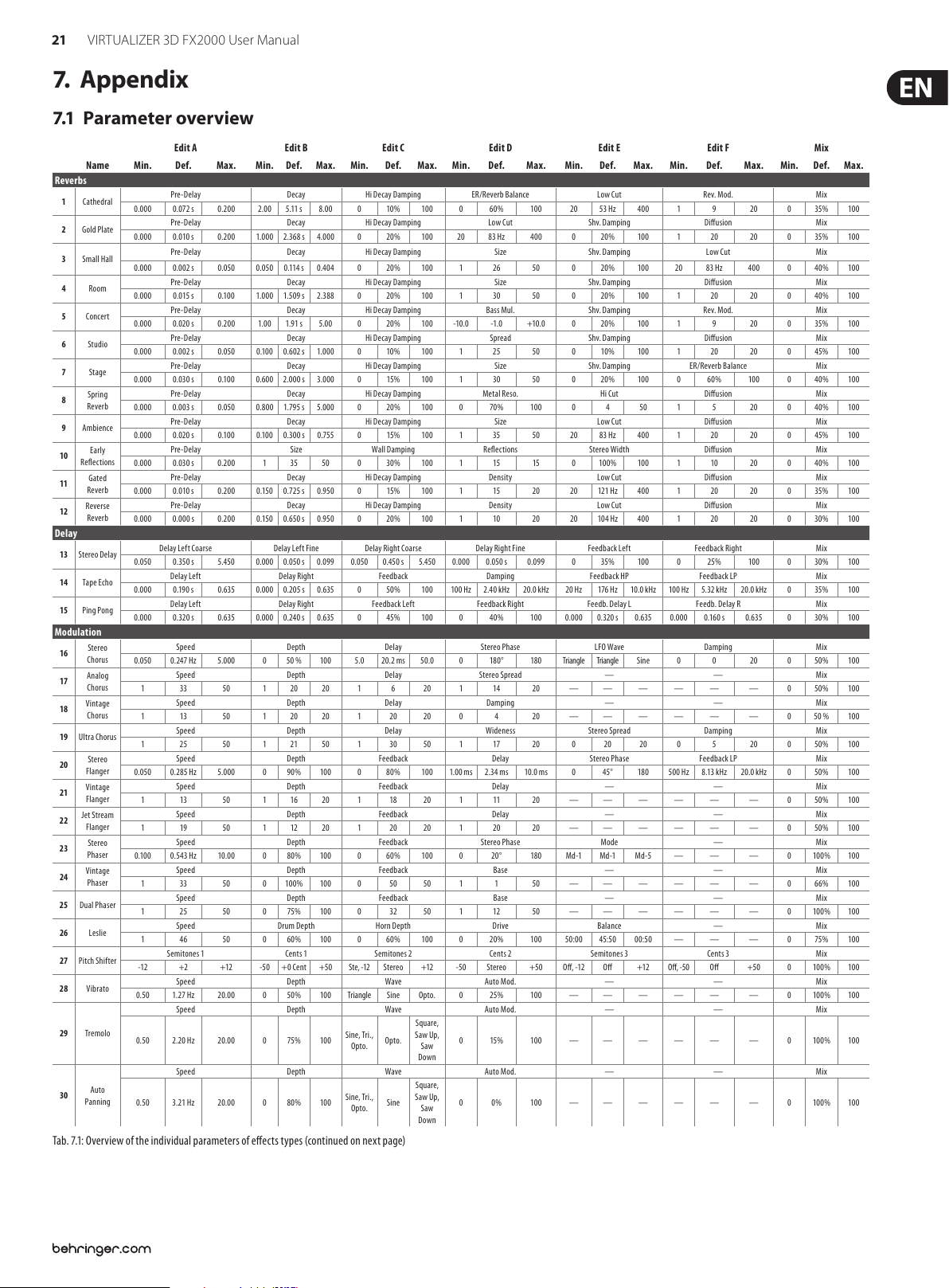
21 VIRTUALIZER 3D FX2000 User Manual
7. Appendix
7.1 Parameter overview
Edit A Edit B Ed it C Ed it D Ed it E Edit F Mix
Name Min. D ef. Max. Min. Def. Max. Min. Def. Max. Min. D ef. Max. Min. Def. Max. Min. Def. Max. Min. Def. Max.
Reverbs
1 Cathedr al
2 Gold Plate
3 Small Hall
4 Room
5 Concert
6 Studio
7 Stage
Spring
8
Reverb
9 Ambience
Early
10
Reections
Gated
11
Reverb
Revers e
12
Reverb
Delay
13 Stereo Delay
14 Tape Echo
15 Ping Pong
Modulation
Stereo
16
Chorus
Analog
17
Chorus
Vintage
18
Chorus
19 Ultra Chorus
Stereo
20
Flanger
Vintage
21
Flanger
Jet Stre am
22
Flanger
Stereo
23
Phaser
Vintage
24
Phaser
25 Dual Phaser
26 Leslie
27 Pitc h Shifter
28 Vibrato
29 Tremolo
Auto
30
Panning
Tab. 7.1: Overvi ew of the individua l parameters of e ects type s (continued on nex t page)
Pre-Delay Decay Hi De cay Dampin g ER/Reverb Balance Low Cut Rev. Mod. Mix
0.000 0.072 s 0.200 2.00 5.11 s 8.00 0 10% 100 0 60% 100 20 53 H z 4 00 1 9 20 0 35% 100
Pre-Delay Decay Hi De cay Dampin g L ow Cut Shv. Damping Diusion Mix
0.000 0.010 s 0.200 1.000 2.368 s 4.000 0 20% 100 20 83 Hz 400 0 20% 100 1 20 20 0 35% 100
Pre-Delay Decay Hi De cay Dampin g Size Shv. Damping Low Cu t Mix
0.000 0.002 s 0.050 0.050 0.114 s 0.4 04 0 20% 100 1 26 50 0 20 % 100 20 83 Hz 400 0 4 0% 100
Pre-Delay Decay Hi De cay Dampin g Size Shv. Damping Diusion Mix
0.000 0. 015 s 0.10 0 1.000 1.509 s 2.38 8 0 20% 100 1 30 50 0 20% 100 1 20 20 0 40% 100
Pre-Delay Decay Hi De cay Dampin g Bass Mul. Shv. Damping Rev. Mod. Mix
0.000 0.020 s 0.200 1.00 1.91 s 5.0 0 0 20% 100 -10 .0 -1.0 +10.0 0 20% 100 1 9 20 0 35% 100
Pre-Delay Decay Hi De cay Dampin g Spread Shv. Damping Diusion Mix
0.000 0.002 s 0.050 0 .100 0.602 s 1.000 0 10% 10 0 1 25 50 0 10% 10 0 1 20 20 0 45% 100
Pre-Delay Decay Hi De cay Dampin g Size Shv. Damping ER/Reverb Balance Mix
0.000 0.030 s 0.10 0 0.600 2.00 0 s 3.000 0 15% 10 0 1 30 50 0 20% 100 0 60% 100 0 40% 10 0
Pre-Delay Decay Hi De cay Dampin g Metal Reso. Hi Cut Diusion Mix
0.000 0.003 s 0.050 0.800 1.795 s 5.000 0 20% 10 0 0 70 % 100 0 4 50 1 5 20 0 40% 100
Pre-Delay Decay Hi De cay Dampin g Size Low Cut Diusion Mix
0.000 0.020 s 0 .100 0.1 00 0.300 s 0.755 0 15% 100 1 35 50 20 83 Hz 400 1 20 20 0 45% 100
Pre-Delay Size Wall Damping Reections Stereo Width Diusion Mix
0.000 0.030 s 0.200 1 35 50 0 30% 10 0 1 15 15 0 10 0% 100 1 10 20 0 40% 100
Pre-Delay Decay Hi De cay Dampin g Density Low Cut Diusion Mix
0.000 0.010 s 0.200 0.15 0 0.72 5 s 0.950 0 15% 100 1 15 20 20 121 Hz 400 1 20 20 0 35% 100
Pre-Delay Decay Hi De cay Dampin g Density Low Cut Diusion Mix
0.000 0.000 s 0.200 0.150 0.650 s 0.950 0 20% 10 0 1 10 20 20 104 Hz 400 1 20 20 0 30% 100
Delay Lef t Coars e Dela y Left Fine Del ay Right Coar se Delay Right Fine Feedback Left Feedback Right Mix
0.050 0.350 s 5.450 0.000 0.050 s 0.099 0.050 0.450 s 5.450 0.000 0.050 s 0.0 99 0 35% 100 0 25% 100 0 30% 100
Delay Lef t Delay Right Feedback Damping Feedback HP Feedback LP Mix
0.000 0 .190 s 0.635 0.000 0.205 s 0.635 0 50% 100 100 Hz 2.40 k Hz 20. 0 kHz 20 Hz 176 H z 10.0 kHz 10 0 Hz 5.32 kHz 20.0 kHz 0 35% 100
Delay Lef t Delay Right Feedback Left Feedback Right Feedb. De lay L Fe edb. Delay R Mix
0.000 0.320 s 0.635 0.000 0.24 0 s 0.635 0 45% 100 0 40% 100 0.000 0.320 s 0.635 0.000 0.16 0 s 0.635 0 30% 100
Speed Depth Delay Stereo Phase LFO Wave Damping Mix
0.050 0.247 Hz 5.000 0 50 % 10 0 5.0 20. 2 ms 50.0 0 180 ° 180 Triangle Triangle Sine 0 0 20 0 50% 100
Speed Depth Delay Stereo Spread — — Mix
1 33 50 1 20 20 1 6 20 1 14 20 — — — — — — 0 50% 100
Speed Depth Delay Damping — — Mix
1 13 50 1 20 20 1 20 20 0 4 20 — — — — — — 0 50 % 10 0
Speed Depth Delay Wideness Stereo Spread Damping Mix
1 25 50 1 21 50 1 30 50 1 17 20 0 20 20 0 5 20 0 50% 100
Speed Depth Feedback Delay Stereo Phase Feedback LP Mi x
0.050 0.285 H z 5.000 0 90% 100 0 80% 100 1.00 ms 2.34 ms 10.0 ms 0 45° 180 500 Hz 8 .13 k Hz 20.0 kHz 0 50% 100
Speed Depth Feedback Delay — — Mix
1 13 50 1 16 20 1 18 20 1 11 20 — — — — — — 0 50% 100
Speed Depth Feedback Delay — — Mix
1 19 50 1 12 20 1 20 20 1 20 20 — — — — — — 0 50% 10 0
Speed Depth Feedback Stereo Phase Mode — Mix
0.10 0 0.543 Hz 10.00 0 80% 100 0 60% 100 0 20° 180 Md -1 Md -1 M d-5 — — — 0 100% 100
Speed Depth Feedback Base — — Mix
1 33 50 0 100% 100 0 50 50 1 1 50 — — — — — — 0 66% 100
Speed Depth Feedback Base — — Mix
1 25 50 0 75% 10 0 0 32 50 1 12 50 — — — — — — 0 10 0% 100
Speed Drum Depth Horn Depth Drive Balance — Mi x
1 46 50 0 60% 10 0 0 60% 100 0 20% 100 50:00 45:5 0 00:50 — — — 0 75% 100
Semito nes 1 Cents 1 Semitone s 2 Cents 2 S emitones 3 Cents 3 Mix
-12 +2 +12 -50 +0 Cent +50 Ste, -12 Stereo +12 -50 Stereo +50 O, -12 O +12 O, -50 O +50 0 10 0% 100
Speed Depth Wav e Auto Mod. — — Mix
0.50 1.27 Hz 20.00 0 50% 100 Triangle Sine Opto. 0 25% 100 — — — — — — 0 100% 100
Speed Depth Wav e Auto Mod. — — Mix
0.50 2.20 Hz 20.00 0 75% 10 0
Speed Depth Wav e Auto Mod. — — Mix
0.50 3.21 H z 20.00 0 80% 100
Sine, Tri.,
Opto.
Sine, Tri.,
Opto.
Opto.
Sine
Square,
Saw Up,
0 15 % 10 0 — — — — — — 0 10 0% 100
Saw
Down
Square,
Saw Up,
0 0% 10 0 — — — — — — 0 100% 100
Saw
Down
Page 22

22 VIRTUALIZER 3D FX2000 User Manual
Edit A Edit B Ed it C Ed it D Ed it E Edit F Mix
Name Min. D ef. Max. Min. Def. Max. Min. Def. Max. Min. D ef. Max. Min. Def. Max. Min. Def. M ax. Min. De f. Max.
Dynamics
31 Compressor
32 Exp ander
33 Gate
Analog
34
Compr./
Limiter
35 Ult ramizer
36 Denoiser
37 De-Esser
Wave
38
Designer
Psycho Accoustic
39 Exci ter
40 Enhancer
41 Ultra Bass
Stereo
42
Imager
43 Ultra Wide
44 Binauralizer
Filter / EQ
45 Auto Filter
46 LFO Filter
Parametric
47
EQ
48 Graphic EQ
Distortion / Amp Simulation
Vocal
49
Distortion
Tube
50
Distortion
51 Guitar Amp
52 Tr i Fuz z
Speaker
53
Simulation
LFO: 0.10 Hz
Ring
54
55 LoFi
Modulator
ENV: 0.005 s
SINE: 1.0 Hz
Tab. 7.1: Overvi ew of the individua l parameters of e ects type s (continued on nex t page)
Ratio Threshold Makeup-Gain Soft Knee Attack Relea se Mix
1.25 3.75 100 -60 -28 dB 0 +0. 0 +3 .0 dB +24 .0 0 4 6 0.005 0.037 s 0.200 0.0 50 0.18 3 s 1.000 0 (o) 100% 10 0 (on)
Ratio Threshold Makeup-Gain Soft Knee Attack Relea se Mix
1.25 3.25 100 -60 -9 dB 0 +0.0 +4.5 dB +24 .0 0 3 6 0.005 0.04 9 s 0.200 0. 050 0.243 s 1.000 0 (o) 100% 10 0 (on)
Hold Threshold Attack Release Range — Mix
0.001 0.0 54 s 1.000 O, -59 -12 dB -1, Mu te 0.005 0.005 s 0.200 0.005 0.031 s 0.500 Mute, -59 Mute -1, 0 dB — — — 0 (o ) 100% 100 (o n)
Ratio Threshold Makeup-Gain Limiter Thresh. Attack Release Mix
1.50 3.00 100 -48 -24 dB 0 +0.0 +6.0 dB +24. 0 -24.0 0.0 dB 0.0 0.001 0 .020 s 0 .150 0.050 s Auto
Density Range Speed Split Frequency St ereo FX Enhancer Freq. Band
1 36 10 0 0 9 dB 24 1 38 100 50 190 Hz 10.0 k 0 20% 100 2.50 k 12.5 k Hz 15.0 k Low Wide High
LP-Frequency LP-Depth LP-Speed Gate Threshold Gate Hol d Gate Resp. Mix
40 916 Hz 20.0 k 0 75 % 10 0 0.0 01 0.243 s 2.000 O, -59 -30 dB -1, M ute 0.001 0.035 s 1.000 0.005 0 .037 s 0.200 0 (o ) 100% 100 (on)
Ratio Threshold Makeup-Gain Frequenc y Atta ck Release Band
1.50 3.00 100 -48 -36 dB 0 +0.0 +6.0 dB +24.0 500 2.78 k Hz 15.0 k 0. 001 0.020 s 0.15 0 0.05 0 s Auto
Attac k Left Release Left Attack Right Release Right Gain Lef t Gain Right Mix
-50 -2 5 +5 0 -50 +2 5 +50 Ste., -50 Ste reo +50 Ste., -50 Stereo +50 Au to, -24 Au to +2 4 dB
Frequency Filter Q Harmonics Timbre Harmon. Kick — Mix
1.00 7. 09 kH z 10.0 1 1 20 0 25% 100 0 50% 100 O On On — — — 0 40% 10 0
High Freq. High Gain Bass Width Ba ss Gain Mid Q Mid Gain Gain
1 42 50 0 30 % 100 -50 +3 0 +50 0 35 % 100 1 30 50 0 10% 10 0 -16 -1 d B +1 6
Subbass Freq. Subbass Level Harmon. Freq. Harmon. Level Harmon. Density Bass G ain Mix
80.0 13 0.6 Hz 150.0 0 25 % 100 30.0 201.2 Hz 250.0 0 50% 100 1 7 7 0 60% 10 0 0 (o ) 100% 100 (on)
Spread MS-Balance Spread Mode Gain Stereo Balance Mono Balance Mix
0 50% 100 0 75% 100 Spread Space Space -6.0 +1.0 dB +6.0 0 50% 100 0 50% 100 0 (o ) 100% 100 (o n)
Center Spread X-Over Frequ. Gain — — Mix
0 25% 10 0 0 50% 100 100 511 H z 10. 0 k -12.0 - 6.0 dB +12.0 — — — — — — 0 (o ) 100% 100 (on)
Center Space Mode Gain Speaker Distance Speaker Compens. Mix
0 40% 100 0 32% 10 0 Phones Speakers Sp eakers -12.0 +5.0 d B +12.0 0 4 18 25 50 % 100 0 (o ) 100% 1 00 (on)
Base Fre q. Depth Typ e Resonance Attac k Release Mix
100 368 Hz 15.0 k 0 30 % 100
Base Fre q. Depth Typ e Resonance Speed Wave Mix
100 48 5 Hz 15.0 k 0 85% 100 L P.1 2 L P.12
Gain 1 Freq. 1 Q 1 Ga in 2 Fr eq. 2 Q 2 Gain
-16 +4 d B +16 200 48 9 Hz 10 .0 k 0.50 1.1 6 10.0 0 -16 +6 dB +16 200 Hz 2.58 kH z 10.0 kHz 0.50 1.03 10. 00 -16 -3 dB +1 6
200 Hz 400 Hz 80 0 Hz 1.6 kHz 3.2 k Hz 6.4 kHz Gain
-16 +3 dB +16 -16 -1 d B +16 -16 +3 dB +16 -16 -1 +1 6 -1 6 +1 dB +16 -16 +3 dB +16 -16 -2 dB +16
Distortion Delay Gain Delay Flanger Level Type Flanger Speed Mix
1 51 10 0 0 30% 10 0 0.050 0.18 7 s 1.000 0 100% 100 1 3 3 0.0 50 0 .202 Hz 2.000 0 10 0% 100
Drive Pre HP Pre LP Damp Tube Select Mid EQ Mix
1 50 100 50 120 Hz 1. 00 k 1. 00 2.07 kHz 15.0 15.0 7.11 kHz 1. 00 1 2 3 -16 -1 dB +16 0 100 % 100
In Gain Drive Presence Gain Cabinet Type Mid EQ Mix
1 60 100 1 70 100 1 70 100 1 75 10 0 1 2 8 -16 0 dB +16 0 100 % 100
In Gain Low-Fuz z Mid-Fuzz Hi-Fuz z Drive Hi Damp Mix
1 80 100 1 51 100 1 55 100 1 51 10 0 1 65 100 1 50 10 0 0 10 0% 100
Type EQ-Gain EQ-Frequency EQ-Q — — Mix
1 5 8 -16 0 dB +1 6 200 Hz 1.44 k Hz 10.0 kHz 0.5 0 2. 24 10.00 — — — — — — 0 100 % 100
Speed Depth Carrier-Freq. Tone Mode Slewing Mix
LFO: 10.00 H z
ENV: 0.500 s
0.40 Hz
RAND +
Bits Resolution To ne Bu zz Level Noise Gain Noise HP Noise LP Mi x
24 7 b it 6
RAND +
SINE: 100.0 H z
0 25% 10 0 100 Hz 308 Hz 10.0 kHz 200 H z 2.0 0 kHz 20.0 kH z LFO LFO
20.0
6.96 kHz 400 Hz 0 30% 100 0 35% 10 0 20 159 Hz 20.0 k 400 Hz 10.3 k Hz 20.0 kHz 0 10 0% 100
kHz
LP. 12,
LP. 24 ,
HP. 12,
HP. 24
BP. 12
BP. 12,
1 34 50 0.005 0.022 s 2.000 0.005 0 .061 s 2.000 0 10 0% 100
BP. 24
LP. 24 ,
HP. 12,
HP. 24 ,
1 35 50 0.10 4.84 Hz 20.00
BP. 12,
BP. 24
ENVELOPE,
RANDOM,
SINE
Auto,
-24
Sine,
Triangle
0 0% 10 0 0 10 0% 100
0.977s,
0 (o ) 100% 10 0 (on)
Auto
0.977s,
Auto
Auto +24 d B 0 (o ) 100% 100 (o n)
Saw Up,
Saw Down
Saw Down ,
Square
Low Wide High
0 100% 100
Page 23

23 VIRTUALIZER 3D FX2000 User Manual
Edit A Edit B Ed it C Ed it D Ed it E Edit F Mix
Name Min. D ef. Max. Min. Def. Max. Min. Def. Max. Min. D ef. Max. Min. Def. Max. Min. Def. M ax. Min. De f. Max.
Special FX
56 Vinylizer
57 S ampler
58 Vocoder
Voice
59
Canceler
60 Resonator
Combination
Chorus &
61
Reverb
Flanger &
62
Reverb
Leslie &
63
Reverb
Pitch Shi fter
64
& Reverb
Delay &
65
Reverb
Tremolo &
66
Reverb
Phaser &
67
Reverb
Chorus &
68
Delay
Flanger &
69
Delay
Pitch Shi fter
70
& Delay
Tremolo &
71
Delay
LFO: 0.10 Hz
ENV: 0.005 s
RAND: 1.0 Hz
Speed Clicks Level Scratch Level Noise Level Ton e Noise Freq. Mi x
20.0 45.0 rpm 80.0 0 10 0% 100 0 50% 100 0 45% 100 0 30 50 0 39 50 0 100% 100
Rec/Stop Play/Stop Speed Mode Rec Gain Overdub Gain Mix
Stop Stop Rec Stop Stop Play -1/ 2, Ba ck Fwrd.
Sensitivity Mode Attack Release Frequency Resonance Mix
0 60% 100
Bass Fre q. MS-Balance Treble Pan Gain — — Mix
20 43 Hz 1.00 k 0 50% 10 0 0 50% 100 -6.0 +6.0 dB +6.0 — — — — — — 0 (o ) 100% 10 0 (on)
Speed Depth Carrier Freq. Feedback Mode Slewing Mix
LFO: 10.00 H z
0.40 Hz
RAND: 100 .0 Hz
Speed Depth Delay Reverb Mix De cay Hi Damp Mix
0.050 0.547 H z 5.000 0 70% 100 5.0 ms 19. 5 ms 5 0.0 ms 0 40% 100 0.50 2.51 s 5.0 0 0 30% 100 0 60% 100
Speed Depth Feedback Reverb Mix Decay Hi Damp Mix
0.050 0.256 H z 5.000 0 71% 100 -80 +80% +80 0 40% 100 0.50 2.02 s 5.00 0 25% 100 0 60% 100
Speed Depth Doppler Reverb Mix Decay Hi Damp Mix
0.50 8.00 H z 8.00 0 90% 10 0 0 80% 100 0 25% 100 0.50 2.42 s 5.0 0 0 30% 100 0 80% 100
Semitones Cents High Cut Reverb Mix Decay Hi Damp Mix
-12 +4 +12 -50 + 0 Cent +50 0 10% 100 0 25% 100 0.50 2.02 s 5.0 0 0 30% 100 0 100 % 100
Delay Feedback Type Reverb Mix D ecay Hi Damp Mix
0.030 0.235 s 0.665 0 40% 100
Speed Depth Auto Mod. Reverb Mix Dec ay Hi Damp Mix
1.00 4 .04 Hz 10. 00 0 80% 100 0 20% 10 0 0 50% 100 0.5 0 2.80 s 5.0 0 0 30% 100 0 70% 100
Speed Depth Feedback Reverb Mix Decay Hi Damp Mix
0.050 0.306 H z 5.000 0 10 0% 10 0 0 70 % 10 0 0 25% 100 0. 50 3.06 s 5. 00 0 20% 100 0 75% 10 0
Speed Depth Mo d. Delay Delay Mix Delay Time Delay Feedback Mix
0.050 0. 318 Hz 5.000 0 100% 100 5.0 ms 17.8 m s 50.0 ms 0 30% 100 0.030 0.350 s 0.665 0 40% 10 0 0 65% 100
Speed Depth Feedback Delay M ix Delay Time Delay Feedback Mix
0.050 0. 318 Hz 5.000 0 80% 10 0 -80 +80% +8 0 0 30 % 100 0.030 0.350 s 0.665 0 40% 10 0 0 55% 100
Semitones Cents High Cut De lay Mix Delay Time Delay Feedback Mix
-12 +4 +12 -50 + 0 Cent +50 0 0% 10 0 0 30% 100 0.030 0.350 s 0.665 0 40% 100 0 6 5% 100
Speed Depth Auto Mod. Delay Mix Delay Time Delay Feedback Mix
0.50 0.73 Hz 20.00 0 95% 100 0 25% 100 0 15% 10 0 0.030 0.190 s 0.665 0 40% 10 0 0 75% 100
ENV: 0.500 s
In-L.,
Pulse Noise 0.005 0. 025 s 0.200 0. 005 0.04 0 s 0.2 00 0 18 50 0 25 50 0 100% 100
Pulse
0 40 % 10 0 20 0 800 Hz 10.0 k -10 0 -80% +10 0 LFO LFO
Stereo,
Spread
Spread
Forward,
Loop Loop Once -12 0 dB 0 -12 0 dB 0 0 50% 100
+1/2
ENVELOPE,
Ping
Pong,
0 50% 100 0.50 4.02 s 5.00 0 30% 100 0 50% 10 0
Tape
0 0% 10 0 0 10 0% 100
RANDOM
Page 24

24 VIRTUALIZER 3D FX2000 User Manual
7. 2 MIDI implementation
MIDI Implementation Chart
Function Transmitted Recognized Remarks
Basic
Channel
Mode
Note Number Tr ue Voi ce
Velocity
Af ter Tou ch
Pitch Bender X X
Control 0,102 - 116 0,102 - 116
Progr. Change Tru e #
System Exclusive O O
System Common
System
Real Time
Aux Messages
Notes
O = YES, X = NO
Mode 1: OMNI ON, POLY
Mode 2: OMNI ON, MONO
Mode 3: OMNI OFF, POLY
Mode 4: OMNI OFF, MONO
Tab. 7. 2: MIDI implementat ion chart
Default
Changed
Default
Messages
Altered
Note ON
Note OFF
Key´s
Ch ´s
Song Pos
Song Sel
Tune
Clock
Commands
Local ON/O FF
All notes OFF
Active S ense
Reset
OFF, 1 - 16
OFF, 1 - 16
1,2, 3,4
X
X
X
X
X
X
X
X
O (0-99)
1-10 0
X
X
X
X
X
X
X
X
X
OFF, 1 - 16
OFF, 1 - 16
1,2, 3,4
X
X
X
X
X
X
X
X
O (0-99)
1-10 0
X
X
X
X
X
X
X
X
X
memorized
Parameter Name Display Range
Bank Sele ct I.001 .. 100/ U.001 .. 100 0 0 = ROM / 1 = R AM
Algorithm Algorithm Name 102 0 .. 70
Edit A Depends on eect 103 Depends on eect
Edit B Depends on eect 104 Depends on eect
Edit C Depends on eect 105 Depends on eect
Edit D Depends on eect 106 Depends on eec t
Edit E Depends on eect 10 7 Depends on eect
Edit F Depends on eect 108 Depends on eect
EQ Low -16 .. +16 dB 109 0 .. 32
EQ High -16 .. +16 dB 110 0 .. 32
Mix Depends on eect 111 Depends on eect
Store U.001 .. U.100 112 0 .. 9 9
In/Out BYP/0 .. 100% 113 0 = BYP / 1 = MIX
Combination Mode SER 1, SER 2, PARA 114 0 = S1 / 1 = S2 / 2 = PA
Input Mode MONO, STER 115 0 = MONO / 1 = STER
External/Internal Mix E XTN/INTN 116 0 = EXT N / 1 = INTR
Tab. 7. 2: Controller func tions with MIDI
MIDI Contr ol
Number
Control Value Range
Page 25

25 VIRTUALIZER 3D FX2000 User Manual
8. Specications
Analog Inputs
Connectors XLR and ¼" TRS
Type RF ltered, servo-balanced input stage
Impedance 80 kΩ balanced
Nominal Operating Level -10 dBV or +4 dBu (selectable)
Max. Input Level +15 dBu at +4 dBu nominal level,
+1 dBV at -10 dBV nominal level
Analog Outputs
Connectors XLR and ¼" TRS
Type Electronically servo-balanced output stage
Impedance 80 Ω balanced
Max. Output Level +15 dBu at +4 dBu nominal level,
+1 dBV at -10 dBV nominal level
System Specications
Bandwidth 20 Hz to 20 kHz, +/- 3 dB
SNR 91 dB, unweighted, 20 Hz to 20 kHz
THD 0.018% typ. @ +4 dBu, 1 kHz,
0 dBu input, gain 1
Power Supply
Voltage
USA/Canada 120 V~, 60 Hz
Europe/U.K./Australia 230 V~, 50 Hz
Japan 100 V~, 50 - 60 Hz
General export model 120/230 V~, 50 - 60 Hz
Fuse 100 - 120 V~: T 200 mA H 250 V
200 - 240 V~: T 100 mA L 250 V
Power Consumption 15 Watts max.
Mains Connection Standard IEC receptacle
Physical
Dimensions (H x W x D) approx. 1 ¾ x 19 x 8" / 44 x 482,6 x 204,4 mm
Net Weight approx. 4 ½ lbs / 2 kg
Shipping Weight approx. 6 ⁄ lbs / 3 kg
BEHRINGER i s constantly str iving to maintain the h ighest profess ional standards. A s a result of these e ffort s,
modific ations may be made f rom time to time to exi sting product s without prio r notice. Specif ications and
appearance m ay differ fro m those listed or illus trated.
Crosstalk < -76 dB
MIDI Interface
Type 5-pin DIN-socket IN / OUT / THRU
Digital Processing
Converters 24-bit Sigma-Delta, 64/128-times oversampling
Sampling Rate 46.875 kHz
Display
Type 4-digit 14 segment alpha-numeric LED-Display
Page 26
26 VIRTUALIZER 3D FX2000 User Manual
FEDERAL COMMUNICATIONS
COMMISSION COMPLIANCE
INFORMATION
VIRTUALIZER 3D FX2000
Responsible Party Name: MUSIC Group Services US Inc.
Address: 18912 North Creek Parkway,
Suite 200 Bothell, WA 98011,
USA
Phone/Fax No.: Phone: +1 425 672 0816
Fax: +1 425 673 7647
VIRTUALIZER 3D FX2000
complies with the FCC rules as mentioned in the followingparagraph:
This equipment has been tested and found to comply with the limits for a ClassB
digital device, pur suant to part 15 of the FCC Rules. These limits are designed
to provide reasonable protection against harmful interference in a residential
installation. This equipment generates, uses and can radiate radio frequency
energy and, if not installed and used in accordance with the instructions, may cause
harmful interference to radio communications. However, there is no guarantee that
interference will not occur in a par ticular installation. If this equipment does cause
harmful interference to radio or television reception, which can be determined
by turning the equipment o and on, the user is encouraged to try to correct the
interference by one or more of the followingmeasures:
• Reorient or relocate the receiving antenna.
• Increase the separation between the equipment and receiver.
• Connect the equipment into an outlet on a circuit dierent f rom that to which the
receiver is connected.
• Consult the dealer or an experienced radio/TV technician forhelp.
This device complies with Part 15 of the FCC rules. Operation is subjec t to the
following two conditions:
(1) this device may not cause harmful interference, and
(2) this device must accept any inter ference received, including inter ference that may
cause undesired operation.
Important information:
Changes or modications to the equipment not expressly approved by MUSIC Group
can void the user’s authority to use the equipment.
Page 27

27 VIRTUALIZER 3D FX2000 User Manual
Page 28

We Hear You
http://acctech.ru/cat/protsessory_effektov/
 Loading...