

Page 1
User Manual
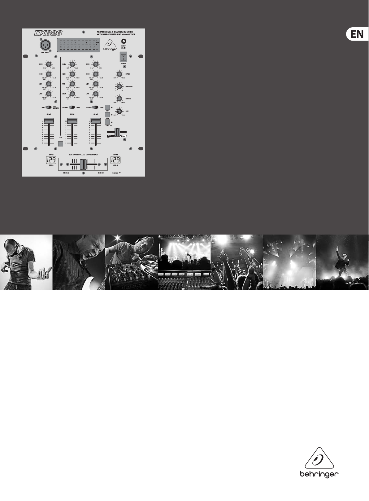
PRO MIXER DX626
Professional 3-Channel DJ Mixer with
BPM Counter and VCA Control
Page 2

2 PRO MIXER DX626 User Manual
Table of Contents
Thank you .......................................................................2
Important Safety Instructions ...................................... 3
Legal Disclaimer ............................................................. 3
Limited warranty ............................................................ 3
1. Introduction ............................................................... 4
1.1 Before you begin ................................................................ 4
2. Control Elements ....................................................... 4
2.1 Front panel ............................................................................ 5
2.2 Rear panel ............................................................................. 6
3. Specications ............................................................. 7
Thank you
Your purchase of the BEHRINGER PRO MIXER DX626 has put you at the forefront
of today’s trends in DJ mixing consoles. Numerous features such as the talkover
function and the beat counter enable you to work in completely new and creative
ways. The DX626 is a mixer for professional use, it is extremely easy to operate
and it helps you give free rein to your creativity.
Page 3
3 PRO MIXER DX626 User Manual
9. Do not defeat the safety purpose of the polarized
TO BIND MUSICGROUP BY ANY EXPRESS OR IMPLIED
Important Safety Instructions
Terminals marked with this symbol carry
electrical current of su cient magnitude
to constitute risk of electric shock.
Use only high-quality professional speaker cables with
¼" TS or twist-locking plugs pre-installed. Allother
installation or modi cation should be performed only
by quali edpersonnel.
This symbol, wherever it appears,
alertsyou to the presence of uninsulated
dangerous voltage inside the
enclosure-voltage that may be su cient to constitute a
risk ofshock.
This symbol, wherever it appears,
alertsyou to important operating and
maintenance instructions in the
accompanying literature. Please read the manual.
Caution
To reduce the risk of electric shock, donot
remove the top cover (or the rear section).
No user serviceable parts inside. Refer servicing to
quali ed personnel.
Caution
To reduce the risk of re or electric shock,
do not expose this appliance to rain and
moisture. The apparatus shall not be exposed to dripping
or splashing liquids and no objects lled with liquids,
suchas vases, shall be placed on the apparatus.
Caution
These service instructions are for use
by quali ed ser vice personnel only.
Toreduce the risk of electric shock do not per form any
servicing other than that contained in the operation
instructions. Repairs have to be performed by quali ed
servicepersonnel.
or grounding-type plug. A polarized plug has two blades
with one wider than the other. A grounding-type plug
has two blades and a third grounding prong. The wide
blade or the third prong are provided for your safety. Ifthe
provided plug does not t into your outlet, consult an
electrician for replacement of the obsolete outlet.
10. Protect the power cord from being walked on or
pinched particularly at plugs, convenience receptacles,
and the point where they exit from the apparatus.
11. Use only attachments/accessories speci ed by
themanufacturer.
12. Use only with the
cart, stand, tripod, bracket,
or table speci ed by the
manufacturer, orsold with
the apparatus. When a cart
is used, use caution when
moving the cart/apparatus
combination to avoid
injury from tip-over.
13. Unplug this apparatus during lightning storms or
when unused for long periods of time.
14. Refer all servicing to quali ed service personnel.
Servicing is required when the apparatus has been
damaged in any way, such as power supply cord or plug
is damaged, liquid has been spilled or objects have fallen
into the apparatus, the apparatus has been exposed
to rain or moisture, does not operate normally, or has
beendropped.
15. The apparatus shall be connected to a MAINS socket
outlet with a protective earthing connection.
16. Where the MAINS plug or an appliance coupler is
used as the disconnect device, the disconnect device shall
remain readily operable.
UNDERTAKING OR REPRESENTATION. THIS MANUAL
IS COPYRIGHTED. NO PART OF THIS MANUAL MAY
BE REPRODUCED OR TRANSMITTED IN ANY FORM
OR BY ANY MEANS, ELECTRONIC OR MECHANICAL,
INCLUDING PHOTOCOPYING AND RECORDING OF ANY
KIND, FOR ANY PURPOSE, WITHOUT THE EXPRESS
WRITTEN PERMISSION OF MUSICGROUPIPLTD.
ALL RIGHTS RESERVED.
© 2013 MUSICGroupIPLtd.
Trident Chambers, Wickhams Cay, P.O. Box 146,
Road Town, Tortola, British Virgin Islands
LIMITED WARRANTY
For the applicable warranty terms and conditions
and additional information regarding MUSIC Group’s
Limited Warranty, please see complete details online at
www.music-group.com/warranty.
1. Read these instructions.
2. Keep these instructions.
3. Heed all warnings.
4. Follow all instructions.
5. Do not use this apparatus near water.
6. Clean only with dry cloth.
7. Do not block any ventilation openings. Install in
accordance with the manufacturer’s instructions.
8. Do not install near any heat sources such as
radiators, heat registers, stoves, or other apparatus
(including ampli ers) that produce heat.
LEGAL DISCLAIMER
TECHNICAL SPECIFICATIONS AND APPEARANCES
ARE SUBJECT TO CHANGE WITHOUT NOTICE AND
ACCURACY IS NOT GUARANTEED. BEHRINGER,
KLARKTEKNIK, MIDAS, BUGERA, AND TURBOSOUND
ARE PART OF THE MUSIC GROUP MUSICGROUP.COM.
ALL TRADEMARKS ARE THE PROPERTY OF THEIR
RESPECTIVE OWNERS. MUSICGROUP ACCEPTS NO
LIABILITY FOR ANY LOSS WHICH MAY BE SUFFERED
BY ANY PERSON WHO RELIES EITHER WHOLLY OR
IN PART UPON ANY DESCRIPTION, PHOTOGRAPH
OR STATEMENT CONTAINED HEREIN. COLORS AND
SPECIFICATIONS MAY VARY FROM ACTUAL PRODUCT.
MUSIC GROUP PRODUCTS ARE SOLD THROUGH
AUTHORIZED FULLFILLERS AND RESELLERS ONLY.
FULLFILLERSAND RESELLERS ARE NOT AGENTS OF
MUSICGROUP AND HAVE ABSOLUTELY NO AUTHORITY
Page 4

4 PRO MIXER DX626 User Manual
1. Introduction
Time is tight, and if you don’t want to be left in the dust you’d better get moving.
To help you along, we have developed an excellent DJ mixing console with the
most popular new features and technologies. It is perfectly suited for use in
dance clubs or for DJ systems and is sure to deliver tons of pure fun.
Be honest: who really likes to read manuals? We know you want to get started
right away, but it is only after reading these instructions that you will fully
understand and be able to properly use all the features your DX626 has to oer.
Take the time to read everything through!
◊ This manual first describes the terminology used, so that you can
fully understand the DX626 and its functions. Please read the manual
carefully and keep it for future reference.
1.1 Before you begin
Your DX626 was carefully packed in the fac tory and the packaging is designed
to protect the unit from rough handling. Nevertheless, we recommend that
you carefully examine the packaging and its contents for any signs of physical
damage that may have occurred during transit.
2. Control Elements
(14)
◊ If the unit is damaged, please do NOT return it to BEHRINGER, but notify
your dealer and the shipping company immediately. Otherwise claims
for damage or replacement may not be granted.
To avoid overheating, ensure that there is enough space around the unit for
cooling and that the device is not placed near other devices giving o heat.
Warning!
◊ We would like to point out that high volume may damage your hearing
and/or your headphones. Please turn the MASTER control all the way
to the left before turning on the device. Always make sure that the
appropriate volume is set.
(1)
(2)
(3)
(4)
(5)
(6)
(7)
(17)
(18)
(8)
(9)
(10)
(11)
(12)
(13)
(15)
Fig. 2.1: The PRO MIXER DX626’s front pane l
(16)
Page 5

5 PRO MIXER DX626 User Manual
2.1 Front panel
(1) The MIC INPUT is the balanced XLR connector for your dynamic microphone.
(2) The GAIN control is used to line up the input signal of each channel.
(3) Each input channel has a 3-band equalizer (HIGH, MID and LOW) with kill
characteristic. Thus, the signal can be lowered to a much greater extent
(-32dB) than it can be raised (+12 dB). This func tion can be very useful
when, for example, fading a frequency range out of a music track.
◊ The total level also depends on the EQ setting. Thus, you should adjust
the equalizer before regulating the level with the GAIN control.
(4) The MIC/LINE-PHONO switch allows you to choose between the
microphone signal and the line or phono signal on channel 1. The position
of the rear panel PHONO/LINE switch (see (21)) determines whether the
input is switched to the phono or the line level setting of the right-hand
switchposition.
(5) On channels 2 and 3 you determine the input signals with the PHONO/LINE
switch. “Phono” is intended for connecting a turntable. “Line” must be
selected for all other signal sources (e. g. CD or MD players).
◊ Never connect devices with line level to the highly sensitive phono
inputs! The output level of phono pick-up systems is measured in
millivolts, whereas CD players and tape decks have levels measured in
volts, i.e. the level from line signals is up to 100 times higher than that
of the phono inputs.
(12) With the three buttons CH-1, CH-2 and CH-3, you determine the signal
source for the headphones signal. You can preview the channels individually
or listen to all three simultaneously.
(13) The MASTER /CUE fader allows you to control the volume ratio between the
input channels’ signal and the MASTER signal on your headphones.
(14) Here you can read the volume level of the PFL and MASTER signals from
three, 10-character LED displays. The lower LED chain displays the PFL signal
and the two upper LEDs display the right and left MASTER signals.
(15) The PRO MIXER DX626 BPM counter is an extremely useful feature. Itensures
smooth transition from one track to the next, making your session an
absolute success. It can calculate the various tempi of tracks in BPM
(BeatsPer Minute). The left display indicates the tempo on channel 2 and the
right display shows the tempo on channel 3.
(16) The CROSSFADER is for crossfading between channels 2 and 3.
(17) This is the connector for a commercially available 12-volt BNC lamp.
(18) Turn on the DX626 with the POWER button.
(6) Adjust the channel volume with the CHANNEL fader.
(7) The PRO MIXER has a talkover function. This feature is actually quite simple:
by pushing the TALK button, the signal of the other input channels is
lowered (TALK LED lights up), enabling your voice to be heard more clearly
over the microphone.
(8) The MASTER control determines the output volume at the
MASTERoutput(see (27) ).
(9) A BALANCE control for the MASTER output is for shaping the stereo image.
(10) The BOOTH control determines the output volume at the
BOOTHoutput(see(26) ).
(11) The CUE control determines the volume of the headphones signal
(PFLsignal).
◊ The PFL signal is your headphones signal. It enables you to preview
music without affecting the MASTER signal. The headphone channel
signal is taken pre- fader (PFL = Pre-Fader Listening).
(19)
Fig. 2.2: Headphones connector
(19) The HEADPHONES connec tor enables you to preview pieces of music
(PFLsignal) on your headphones. Your headphones should have a minimum
impedance of 32 ohms.
Page 6

6 PRO MIXER DX626 User Manual
2.2 Rear panel
(24) (23) (22) (20)
(30)(21)
(27) (26) (25)
(22) The PHONO inputs from channels 2 and 3 are also for connectingturntables.
(23) These are the LINE inputs from channels 2 and 3 for connecting tape decks,
CD or MD players etc.
(24) The GND connectors ground the turntables.
(25) Using the TAPE output you can record your music by connecting devices such
as tape decks, DAT recorders etc. Unlike the MASTER and BOOTH outputs,
theoutput volume is xed, making it necessary for you to adjust the input
level on the recording device.
(26) The BOOTH output gives you another possible way to connect an amplier.
It is controlled by the BOOTH control on the front panel. Through this output
you can operate monitor speakers or even provide another area with sound.
(27) The MASTER output is for connecting an amplier and is adjusted using the
MASTER control.
◊ Always turn the power amps on last to avoid inrush currents that can
easily damage your speakers. And, to avoid sudden and unpleasant
surprises for your ears, make sure there is no signal at the DX626 before
turning on the power amps. To be sure, slide all the faders to the
bottom and switch all controls to zero.
(28) This is the connector for the power cable. This is where the advantage of the
sophisticated internal power supply can be seen: the pulse behaviour of each
amplifying circuit is mainly determined by the voltage reserves available.
Each mixing console is equipped with numerous operational ampliers
(opamps) to process line level signals. Due to limited output of their power
supplies, many mixing consoles show signs of “stress” when subjec ted to
heavy loads. But not your DJX400: the sound is always clear and transparent.
(29)
(28)
Fig. 2.3: The DX626 rear c onnectors
With the exception of the microphone and headphone connec tors, the PRO MIXER
DX626 only has cinch jacks, which can be found on the rear panel of theconsole.
(20) This is the INPUT 1 input for channel 1. It can be switched to phono or line
input sensitivity.
(21) With the PHONO/LINE switch at the channel 1 input you can choose
between LINE and PHONO input. However, in order to do that,
theMIC/LINE-PHONO switch on the front panel must be switched to
LINE-PHONO (see (4)).
(29) FUSE HOLDER/VOLTAGE SETTING. Before connecting the unit to the mains,
ensure that the voltage setting matches your local voltage. Blown fuses
should only be replaced by a fuse of the same type and rating. On some
units, the fuse holder can be switched to one of two positions, i.e. 230 V and
115 V. N.B: should you desire to operate the unit outside Europe at 115 V,
ahigher fuse rating is required.
(30) PRO MIXER DX626 SERIAL NUMBER. Please take the time to complete
and return the warranty card within 14 days of the date of purchase.
Or,simplyregister online at behringer.com.
Page 7

7 PRO MIXER DX626 User Manual
3. Specications
Audio Inputs
Mic 40 dB Gain, elec. balanced input
Phono 1, 2 and 3 40 dB Gain @ 1 kHz, unbalanced inputs
Line 1, 2 and 3 0 dB Gain, unbalanced inputs
Audio Outputs
Master max. +21 dBu @ +10 dB (Line In)
Booth max. +21 dBu @ +10 dB (Line In)
Tape type. 0 dBu
Phones type. 125 mΩ @ 1% THD
Equalizer (+/-8 dB)
Stereo Low +12 dB/-32 dB @ 50 Hz
Stereo Mid +12 dB/-32 dB @ 1.2 kHz
Stereo High +12 dB/-32 dB @ 10 kHz
Mic Low +12 dB/-32 dB @ 50 Hz
Mic Mid +12 dB/-32 dB @ 1.2 kHz
Mic High +12 dB/-32 dB @ 10 kHz
Power Supply
Mains Voltage
USA / Canada 120 V ~, 60 Hz
U.K. / Australia 240 V ~, 50 Hz
Europe 230 V ~, 50 Hz
General Export Model 100 - 120 V ~, 200 - 240 V ~, 50/60 Hz
Power Consumption max. 15 W
Fuse 100 - 120 V ~: T 500 mA L 250 V
200 - 240 V ~: T 315 mA L 250 V
Mains Connection Standard IEC Receptacle
Dimensions/Weight
Dimensions (H x W x D) approx. 3.6 x 10 x 12"
approx. 91 x 254 x 305 mm
Weight approx. 2.6 kg
BEHRINGER i s constantly str iving to maintain the h ighest profess ional standards. A s a result of these e ffort s,
modific ations may be made f rom time to time to exi sting product s without prio r notice. Specif ications and
appearance m ay differ fro m those listed or illus trated.
Talkover Button (MIC) -16 dB
Lamp (BNC) 12 V/400 mA
Gener al
Signal-to-noise ratio (S/N) > 87 dB (Line)
Crosstalk > 70 dB (Line)
Distortion (THD) < 0.05%
Frequency response 20 Hz - 20 kHz
Gain control range -16 dB - +6 dB
Page 8

8 PRO MIXER DX626 User Manual
FEDERAL COMMUNICATIONS
COMMISSION COMPLIANCE
INFORMATION
PRO MIXER DX626
Responsible Party Name: MUSIC Group Services US Inc.
Address: 18912 North Creek Parkway,
Suite 200 Bothell, WA 98011,
USA
Phone/Fax No.: Phone: +1 425 672 0816
Fax: +1 425 673 7647
PRO MIXER DX626
complies with the FCC rules as mentioned in the followingparagraph:
This equipment has been tested and found to comply with the limits for a ClassB
digital device, pur suant to part 15 of the FCC Rules. These limits are designed
to provide reasonable protection against harmful interference in a residential
installation. This equipment generates, uses and can radiate radio frequency
energy and, if not installed and used in accordance with the instructions, may cause
harmful interference to radio communications. However, there is no guarantee that
interference will not occur in a par ticular installation. If this equipment does cause
harmful interference to radio or television reception, which can be determined
by turning the equipment o and on, the user is encouraged to try to correct the
interference by one or more of the followingmeasures:
• Reorient or relocate the receiving antenna.
• Increase the separation between the equipment and receiver.
• Connect the equipment into an outlet on a circuit dierent from that to which the
receiver is connected.
• Consult the dealer or an experienced radio/TV technician forhelp.
This device complies with Part 15 of the FCC rules. Operation is subjec t to the
following two conditions:
(1) this device may not cause harmful interference, and
(2) this device must accept any inter ference received, including inter ference that may
cause undesired operation.
Important information:
Changes or modications to the equipment not expressly approved by MUSIC Group
can void the user’s authority to use the equipment.
Page 9

We Hear You
 Loading...