

Behringer DSP1100 User Manual

1
User´s Manual
FEEDBACK DESTROYER
DSP1100
English Version 1.1 May 1998
The information contained in this manual is subject to change without notice. No part of this manual may be reproduced or
transmitted in any form or by any means, electronic or mechanical, including photocopying and recording of any kind, for any
purpose, without the express written permission of Behringer GmbH.
ALL RIGHTS RESERVED © 1998 Behringer GmbH. BEHRINGER is a registered trademark.
BEHRINGER INTERNATIONAL GmbH, Hanns-Martin-Schleyer-Str . 36-38, D-47877 Willich-Münchheide II
Tel. +49 (0) 21 54 / 92 06-0, Fax +49 (0) 21 54 / 92 06-30.

2
acc. to the Directives
89/336/EWG and 73/23/EWG
We, BEHRINGER INTERNATIONAL GmbH
Hanns-Martin-Schleyer-Straße 4
D - 47877 Willich
Name and address of the manufacturer or the introducer of the product on the market who is established in the EC
herewith take the sole responsibility to confirm that the product:
FEEDBACK DESTROYER DSP1100
Type designation and, if applicable, Article-N
o
which refers to this declaration, is in accordance with the following standards or
standardized documents:
x EN 60065 x EN 61000-3-2
x EN 55020 x EN 61000-3-3
The following operation conditions and installation arrangements have to be presumed:
acc. to Operating Manual
B. Nier, President Willich, 01.03.1998
Name, address, date and legally binding signature of the person responsible
EG-Declaration of Conformity
Spezielle Studiotechnik GmbH
3
SAFETY INSTRUCTIONS
CAUTION: To reduce the risk of electrical shock, do not remove
the cover (or back). No user serviceable parts inside; refer servicing to qualified personnel.
WARNING: To reduce the risk of fire or electrical shock, do not
expose this appliance to rain or moisture.
DETAILED SAFETY INSTRUCTIONS:
All the safety and operation instructions should be read before the appliance is operated.
Retain Instructions:
The safety and operating instructions should be retained for future reference.
Heed Warnings:
All warnings on the appliance and in the operating instructions should be adhered to.
Follow instructions:
All operation and user instructions should be followed.
Water and Moisture:
The appliance should not be used near water (e.g. near a bathtub, washbowl, kitchen sink, laundry tub, in a
wet basement, or near a swimming pool etc.).
Ventilation:
The appliance should be situated so that its location or position does not interfere with its proper ventilaton.
For example, the appliance should not be situated on a bed, sofa rug, or similar surface that may block the
ventilation openings: or placed in a built-in installation, such as a bookcase or cabinet that may impede the
flow of air through the ventilation openings.
Heat:
The appliance should be situated away from heat sources such as radiators, heat registers, stoves, or other
appliance (including amplifiers) that produce heat.
Power Source:
The appliance should be connected to a power supply only of the type described in the operating instructions
or as marked on the appliance.
Grounding or Polarization:
Precautions should be taken so that the grounding or polarization means of an appliance is not defeated.
Power-Cord Protection:
Power supply cords should be routed so that they are not likely to be walked on or pinched by items placed
upon or against them, paying particular attention to cords and plugs, convenience receptacles and the point
where they exit from the appliance.
Cleaning:
The appliance should be cleaned only as recommended by the manufacturer.
Non-use Periods:
The power cord of the appliance should be unplugged from the outlet when left unused for a long period of
time.
Object and Liquid Entry:
Care should be taken so that objects do not fall and liquids are not spilled into the enclosure through openings.
Damage Requiring Service:
The appliance should be serviced by qualified service personnel when:
- The power supply cord or the plug has been damaged; or
- Objects have fallen, or liquid has been spilled into the appliance; or
- The appliance has been exposed to rain; or
- The appliance does not appear to operate normally or exhibits a marked change in performance; or
- The appliance has been dropped, or the enclosure damaged.
Servicing:
The user should not attempt to service the appliance beyond that is described in the Operating Instructions.
All other servicing should be referred to qualifield service personnel.
This symbol, wherever it appears,
alerts you to the presence of
uninsulated dangerous voltage inside
the enclosure - voltage that may be
sufficient to constitute a risk of shock.
This symbol, wherever it appears, alerts
you to important operating and maintenance instructions in the accompanying
literature. Read the manual.

4
The FEEDBACK DESTROYER
s 2-channel Digital Feedback Destroyer / Parametric EQ powered by a 24-bit high-speed DSP
s 20-bit A/D and D/A converters with 64/128 times oversampling for ultra-high headroom and resolution of
detail
s Automatically and “intelligently” searches out and destroys up to 12 frequencies per channel
s 24 fully programmable Parametric Filters that can be set manually or via MIDI
s “Set-and-forget” default setting enables immediate and super-easy feedback destroyer performance
s Single-Shot mode automatically searches and destroys feedback and remains the filter until you reset
them manually
s Auto mode continously monitors the mix, resetting programmed filters automatically
s Manual mode allows for setting up to 24 fully parametric filters including Frequency, Bandwith and Gain
s Single-Shot, Auto and Manual modes are assignable for each filter
s Two digital processing engines give you independent or coupled functions on left and right channels
s Internal 24-bit processing with professional 48 kHz sampling rate
s Full MIDI capability and user preset memories to store programs for instant recall
s Accurate eight-segment LED level meters simplify level setting for optimum performance
s “Future-proof” software-upgradeable architecture
s Future editor software (free of charge) allows for total remote control via PC
s High-quality components and exceptionally rugged construction ensures long life and durability
s Manufactured under the stringent ISO9000 management system

5
FOREWORD
Dear Customer,
Welcome to the team of FEEDBACK DESTROYER users and thank you very much for expressing your
confidence in BEHRINGER products by purchasing this unit. It is one of my most pleasant tasks to write this
letter to you, because it is the culmination of many months of hard work for our engineering team. Our daily
objective is to be focused on you, the musician and the sound engineer, and with that focus in mind, it drives
us to reach a goal which is unique, and is the backbone of the BEHRINGER philosophy.
It is our philosopy to share our joy with you, because you are the most important member of the BEHRINGER
family. With your highly competent suggestions for new products you`ve greatly contributed to shaping our
company and making it successful. In return, we guarantee you uncompromising quality (manufactured under
ISO9000 certified management system) as well as excellent technical and audio properties at an extremely
favorable price. All of this will enable you to fully unhold your creativity without being hampered by budget
constraits.
We are often asked how we can make it to produce such high-grade devices at such unbelievably low prices.
The answer is quite simple: it`s you, our customers! Many satisfied customers mean large sales volumes
enabling us to get better conditions of purchase for components, etc. Isn´t it only fair to pass this benefit back
to you? Because we know that your success is our success, too!
I would like to thank all the people, whose help on the FEEDBACK DESTROYER has made it all possible.
Everybody has made very personal constributions, starting from the designers of the unit via the many staff
members in our company to you, the user of BEHRINGER products.
Thank you and sincerely yours,
Uli Behringer

6
TABLE OF CONTENT
1. INTRODUCTION ......................................................................................................................7
1.1 Technical background .................................................................................................................... 7
1.1.1 Feedback as a physical phenomenon .................................................................................. 9
1.1.2 Graphic equalizers ............................................................................................................. 10
1.1.3 Parametric equalizers......................................................................................................... 10
1.2 The FEEDBACK DESTROYER.................................................................................................... 10
2. THE CONCEPT......................................................................................................................12
2.1 The quality of components and circuit .......................................................................................... 12
2.2 Two independent channels........................................................................................................... 12
3. INSTALLATION .....................................................................................................................13
3.1 Rack mounting ............................................................................................................................. 13
3.2 Mains voltage ............................................................................................................................... 13
3.3 Audio connections ........................................................................................................................ 13
3.4 Selecting the operating level............................................................................................... .......... 14
4. CONTROL ELEMENTS .........................................................................................................15
4.1 Keys for parameter selection / jog wheel (rotary control).............................................................. 15
4.2 Display and indicators .................................................................................................................. 16
4.3 Rear control elements .................................................................................................................. 16
5. OPERATION ..........................................................................................................................18
5.1 Activating/deactivating the filters .................................................................................................. 18
5.2 Manual filters / parametric equalizer ............................................................................................. 18
5.3 Automatic filters............................................................................................................................ 18
5.4 Working with programs................................................................................................................. 18
5.4.1 Recalling programs ............................................................................................................ 19
5.4.2 Choice of mode .................................................................................................................. 19
5.4.3 Editing filter parameters...................................................................................................... 19
5.4.4 Storing programs................................................................................................................ 20
5.5 MIDI control.................................................................................................................................. 20
5.6 The basics of digital signal processing ......................................................................................... 21
6. APPLICATIONS.....................................................................................................................24
6.1 Using the FEEDBACK DESTROYER in the monitor path............................................................. 24
6.2 Using the FEEDBACK DESTROYER in the main mix bus ........................................................... 24
6.3 Using the FEEDBACK DESTROYER in single channels and sub-groups .................................... 25
6.4 Using the FEEDBACK DESTROYER in a studio environment ..................................................... 26
6.5 Using the FEEDBACK DESTROYER as an effects device .......................................................... 26
6.6 Special remarks............................................................................................................. ............... 26
6.6.1 Level setting ....................................................................................................................... 26
6.6.2 Digital overflow ................................................................................................................... 27
6.6.3 “Tuning in” P.A. and monitor systems................................................................................. 27
7. FREQUENCY CHART ...........................................................................................................28
8. MIDI IMPLEMENTATION ......................................................................................................29
9. SPECIFICATIONS .................................................................................................................30
10. WARRANTY.........................................................................................................................31

7
1. INTRODUCTION
With the FEEDBACK DESTROYER you purchased a highly useful device for the control of sound reinforcement systems, which will enable you to focus your attention on what is essential: your music. The fully
featured FEEDBACK DESTROYER not only suppresses feedback but also incorporates a wealth of additional functions in one single unit. Its 24 separate filters can be edited in all parameters and automatically
detect and suppress feedback frequencies. With its pro-level internal signal processing circuitry, the unit can
also be used as a high-end equalizer for stage and studio applications. The MIDI interface allows for integrating the FEEDBACK DESTROYER into any MIDI system, and the open system architecture enables you to
update the system software whenever you want. In a word: the Behringer FEEDBACK DESTROYER was
built for the next millennium.
1.1 Technical background
The steady development of modern sound reinforcement systems has made it possible to produce almost
any level of loudness. Yet, the increase in loudness goes in line with a need for optimized audio quality.
Today, audiences expect to hear a powerful and transparent sound. Nothing can spoil a live event more than
interference and feedback.
High volume levels and the use of ever sophisticated monitor systems with a great number of speaker boxes
have increased the potential risk of feedback loops. Up to now sound engineers have used conventional 1/3octave equalizers to suppress unwanted feedback. Now, the Behringer FEEDBACK DESTROYER gives
you the option to delegate this task to the FEEDBACK DESTROYER, so that you can pay your music your
undivided attention instead of having to suppress feedback with graphic EQ’s using a trial-and-error approach.
To fully understand how the Behringer FEEDBACK DESTROYER works you will need to know the meaning
of a few fundamental terms used in signal equalization, such as:
s dB, decibel
s quality factor (Q), bandwidth
s octave, 1/3-octave
With the FEEDBACK DESTROYER, as with any other type of equalizer, the amount of boost/attenuation
applied to a specific frequency is expressed in decibels (dB). What’s a decibel? The abbreviation dB is not a
unit (although often used as one), but describes a logarithmic proportion. The entire dynamic range of human
hearing (from the threshold of audibility to a jet-airplane, see fig. 1.1) starts with about 0.00002 Pa (threshold
of audibility) and goes up to 113 Pa (threshold of pain).
The range of sound pressure levels or the dynamic range of human hearing encompasses seven times the
power of ten, which corresponds to a factor of 10,000,000. This enormous range of values is difficult to
handle and additionally does not represent the subjective perception of sound, since human hearing tends to
use a logarithmic curve. When an increase in loudness by the factor two is perceived as one step, four times
the loudness level equals two steps. So, the decibel is a unit of measurement that describes a level in relation
to a reference quantity. To make clear which reference quantity is meant, the abbreviation SPL (sound
pressure level) is sometimes used together with dB. Starting with a value of 0 dB SPL for the threshold of
audibility, any dB values can be calculated by means of the following formula:
L
U
U
=⋅20
2
1
lo
g
whereas L = e.g. the absolute sound pressure level in dB SPL, U1 = e.g. a reference sound pressure of
0.00002 Pa, U2 = e.g. the sound pressure (in Pa) produced by the sound source to be calculated, and log =
decimal logarithm.
1. INTRODUCTION
8
0
20
40
60
80
100
120
140
160
Threshold Of Audibility
Falling Leaves
Recording Studio
Quiet Apartment
Normal Conversation
"Loud" Office
Power Drill
Threshold Of Pain
Jet Engine
Machinery Hall
Sound-Pressure Level (dB SPL)
Fig. 1.1.: Dynamic range of human hearing
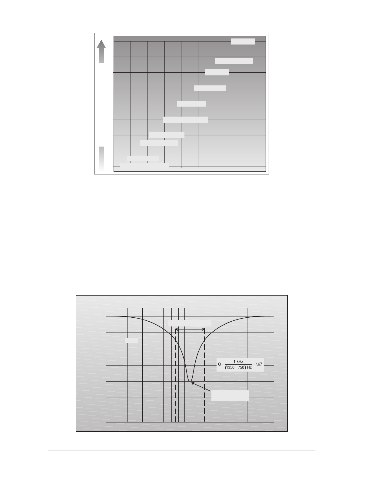
As can be seen, human hearing has a very wide dynamic range of about 130 dB, which surpasses the range
of a DAT or CD player with an approximate range of 96 dB. From a physical point of view, a 6 dB boost
corresponds to an increase in loudness by the factor 2. However, the human ear perceives a signal to be
twice as loud as before only if it is boosted by about 10 dB. This will give you an idea of the variety of sound
manipulations that can be realized with the 24 filters of the FEEDBACK DESTROYER. For each filter, you
can apply a boost of +16 dB or a cut of -48 dB, i.e. you can boost the selected frequency by the subjectively
perceived factor 3 (physically x5) or attenuate it by the factor 27 (physically x250)!
The sound which an EQ produces not only depends on the selected frequency and the amount of gain
(expressed in dB); the bandwidth of the filters also plays an important role. Here, we generally use the socalled
absolute
bandwidth of a filter, which is measured from the lower to the upper cutoff frequency. Starting
from there, you can divide the absolute bandwidth by the filter’s center frequency to calculate the
relative
bandwidth. The
quality factor (Q)
is simply the reciprocal value of the relative bandwidth.
0 dB
-2 dB
-4 dB
-6 dB
-8 dB
-10 dB
-12 dB
1 kHz
5 kHz200 Hz
Bandwidth = 600 Hz
Filter attenuated by 8 dB at 1kHz
Center frequency
= 1 kHz
-3 dB
Fig. 1.2: Typical equalizer filter curve
1. INTRODUCTION
9
The filter bandwidth can also be expressed in
octaves
(as on the FEEDBACK DESTROYER). The following
table shows a list of decimal Q values vs. octaves:
Octa ve Quality fa ctor (Q)
1/6 8.65
1/4 5.76
1/3 4.32
1/2 2.87
3/4 1.90
11.41
3/2 0.92
20.67
30.40
Fig. 1.1: Octaves vs. Q factors
Now the following relationship becomes clear: the higher the Q factor, the narrower the frequency band that
can be cut or boosted. On the Behringer FEEDBACK DESTROYER you can adjust the relative bandwidth
conveniently with the infinitely variable jog wheel. The filter bandwidth can be tuned from 2 octaves (120/60
octaves) down to 1/60 octave (for fine adjustments).
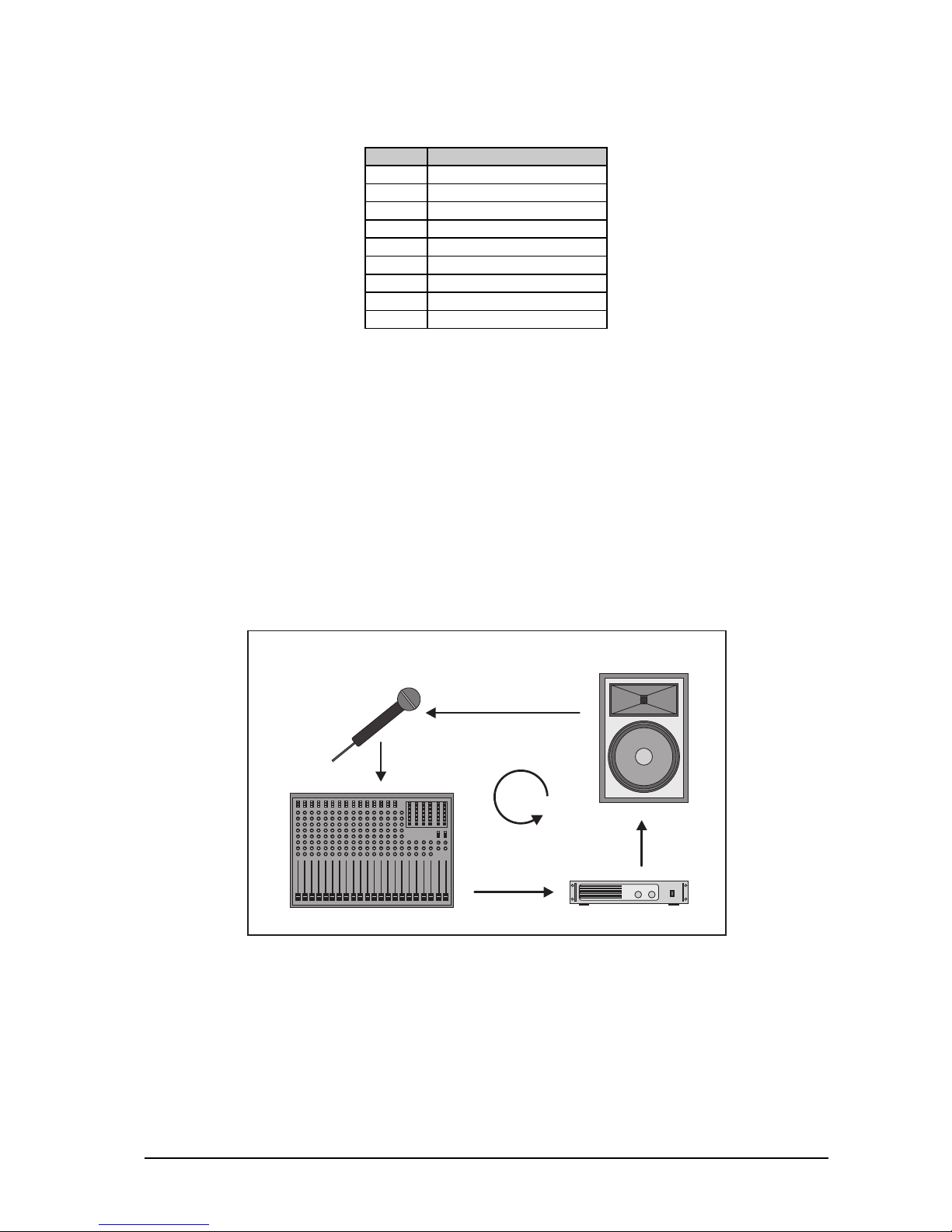
1.1.1 Feedback as a physical phenomenon
Almost every concert goer may have experienced with their own ears the howling and squealing of an
improperly set sound reinforcement system. Feedback is one of the main problems encountered during live
events. A feedback loop is produced when a microphone signal is reproduced by an amplifier system, to be
picked up again (with the same phase position) by the microphone. Thus, feedback is built up at all frequencies
where the distance between microphone and speaker corresponds to a multiple of the signal’s wavelength.
Microphone
Mixing Console
Power Amp
Speaker Box
Fig. 1.3: Typical feedback loop
Basically, any microphone signal passing through an amplifier is liable to generate feedback. Unfortunately,
the feedback frequencies of P.A. systems differ, and even one single system can have varying feedback
frequencies, as these depend largely on the room acoustics. Feedback can be caused by the following
conditions:
s The microphones are too close to the speaker boxes or the speakers are badly positioned (monitor
system).
s The microphone channels on the mixing console are not set up correctly.
1. INTRODUCTION

10
s The microphones used are not operated in accordance with their directivity (e.g. cardioid/super-cardioid).
s The acoustic properties of the room are unfavorable. Tiled walls and floors heavily reflect the sound.
All rooms feature a number of natural resonances sometimes with “high” quality factor. At such frequencies
the potential risk of feedback is increased. In addition to the acoustic properties of the room, the relative
position of the microphone with reference to the loudspeaker plays a decisive role for the generation of
feedback. In practice, this phenomenon can be observed with microphone held directly in front of a speaker,
thus producing feedback. Of course, the first thing to do in such a case is to move the microphone away from
the speaker. When doing so, you can hear the feedback frequency change, because a variation in the
distance between microphone and loudspeaker results in a variation of feedback frequencies. It is therefore
very difficult to anticipate feedback frequencies and avoid their occurrence by means of equalizers with fixed
settings.
1.1.2 Graphic equalizers
Graphic equalizers are part of the audio engineer’s standard equipment for live applications. In this context,
graphic EQ’s usually perform two main tasks:
s Fine tuning the mix to the room acoustics by inserting the EQ in the master inserts of the mixing console.
s To some extent, experienced audio engineers can use graphic EQ’s to manually suppress annoying
feedback.
The 1/3-octave design with 31 faders per channel has become the standard among graphic equalizers. Here,
the spacing between individual filter frequencies is 1/3 octave. The quality factor (Q) of the filters (usually 1
octave) is fixed as are the frequencies controlled with the 31 faders.
1/3-octave equalizers are very popular (e.g. our ULTRA-CURVE DSP8000) because they are so easy to
operate. The fader positions clearly show how the signal is being processed, especially since graphic EQ’s
have fixed frequencies based on the so-call ISO standard. So, all graphic equalizers designed to meet the
ISO standard feature the same fixed frequencies. Once you’ve got used to work with a 1/3-octave equalizer,
you will find the FEEDBACK DESTROYER a highly convenient tool, as it splits up the audio spectrum into the
ISO frequencies (see table 1.2), which enables you to access the most important frequencies quickly. Of
course, you can use the Fine button to fine tune the standard ISO frequencies (in1/60-octave steps) within a
range of 1/3 octave.
Hz
20 25 31.5 40 50 63 80 100 125 160 200 250 315 400 500 630 800
kHz
1 1.25 1.6 2 2.5 3.15 4 5 6.3 8 10 12.5 16 20
Table 1.2: standard ISO frequencies
1.1.3 Parametric equalizers
Parametric equalizers, unlike graphic EQ’s, allow for selecting both the processing frequency and the bandwidth, so that it is possible to process any given signal in full detail. Naturally, this equalizer design can also
be used to “filter” unwanted signals, however, only if these signal have a fixed frequency. If the frequency
changes, the parametric equalizer would have to be readjusted all the time. The majority of (analog) parametric EQ’s suffers from a quite fundamental drawback: they are operated by means of rotary controls, i.e.
contrary to graphic EQ’s, it is much more difficult to make necessary readjustments quickly.
1.2 The FEEDBACK DESTROYER
As you have seen, suppressing feedback with a graphic and/or parametric equalizer often means that you
have to accept compromises. Since feedback signals fail to comply with the standard ISO frequencies of
graphic EQ’s and additionally can have changing frequencies, their suppression with a graphic equalizer is
more or less a matter of luck.
Example: let’s assume a feedback signal at 1.8 kHz is produced during a concert. To suppress it, you’ve got
to cut the 1.8 kHz band on your EQ. However, since graphic equalizers only have 1.6 and 2 kHz bands, you
might need to attenuate both bands. Result: although feedback will be eliminated due to the low filter quality,
1. INTRODUCTION
 Loading...