

Page 1

Userss Manual
DSP110
®
ENGLISH
Version 1.2 April 2001
SHARK
www.behringer.com
Page 2

SHARK DSP110
2
Page 3

SHARK DSP110
1. INTRODUCTION
Thank you very much for expressing your confidence in BEHRINGER products by
purchasing the SHARK DSP110.
+ This manual first describes the terminology used, so that you can fully
understand the DSP110 and its functions. Please read the manual carefully
and keep it for future reference.
1.1 The concept
With the SHARK DSP110 you purchased a device that combines an automatic Feedback
Destroyer using the ingenious search algorithms of our FEEDBACK
DESTROYERPRO DSP1124P, a variable Delay Line (adjustable in msec, feet and
meter), a ULN (Ultra-Low Noise) microphone pre-amp with Phantom Power, an
automatic Noise Gate, a variable Low Cut filter and a Compressorall in one ultrarugged and compact case. Still, the SHARK can be operated intuitively and expanded
to a multi-channel system using another four SHARKs and an optionally available 19"
rack mount kit. The SHARKs 24-bit A/D and D/A converters guarantee a precise
reproduction of your program material.
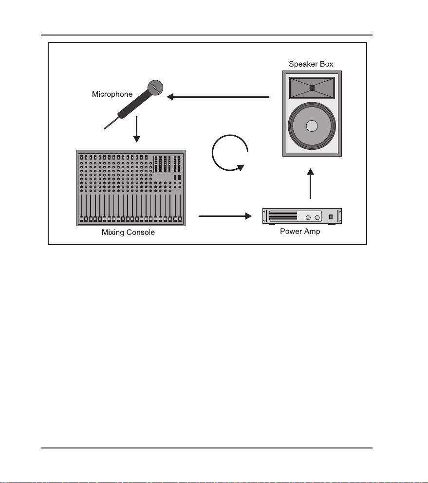
High volume levels and the use of ever more sophisticated monitoring systems with
a multitude of speaker cabinets have led to a greater potential risk of feedback loops
in sound reinforcement systems. So far, audio engineers have been using conventional
1/3-octave equalizers to suppress unwanted feedback. However, the individual filters
of such an EQ, with their relatively wide bandwidth, have quite an impact on the sound
image. With the BEHRINGER SHARK (minimum bandwidth: 1/60 of an octave) you
are now free to either choose the trial and error method to suppress feedback with
graphic equalizers, or to assign this task to the DSP110, so that you can give your
music your undivided attention. Using extremely narrow-bandwidth filters, the
SHARKDSP110 eliminates only unwanted feedback, without affecting your music.
1. INTRODUCTION
3
Page 4
SHARK DSP110
Fig. 1.1: Typical feedback loop
1.2 Before you begin
Your SHARK was carefully packed in the factory and the packaging is designed to
protect the unit from rough handling. Nevertheless, we recommend that you carefully
examine the carton and its contents for any signs of physical damage, which may have
occurred during transit.
+ If the unit is damaged, please do not return it to BEHRINGER, but notify
your dealer and the shipping company immediately, otherwise claims for
damage or replacement may not be granted. Shipping claims must be made
by the consignee.
The optionally available rack mount kit allows you to mount your BEHRINGER SHARK
in a standard 19" rack, together with another four SHARKs. The rack mount kit requires
2U of rack space.
4
1. INTRODUCTION
Page 5

SHARK DSP110
Be sure that there is enough air space around the unit for cooling and please do not
place the SHARK on high-temperature devices such as power amps, etc. to avoid
overheating.
Please use the enclosed power supply to connect the unit to the mains. The supply
complies with all applicable safety standards.
+ Please note that all units must be grounded properly. For your own safety,
you should never remove any ground connectors from electrical devices
or power cords or render them inoperative.
Further information can be found in chapter 3 INSTALLATION.
As a standard the audio inputs and outputs of the BEHRINGER SHARK DSP110 are
fully balanced. If possible, connect the unit to other devices in a balanced configuration
to allow for maximum interference immunity. The automatic servo function detects
unbalanced connections and compensates the level difference automatically (6dB
correction).
1. INTRODUCTION
5
Page 6
SHARK DSP110
1.3 Control elements
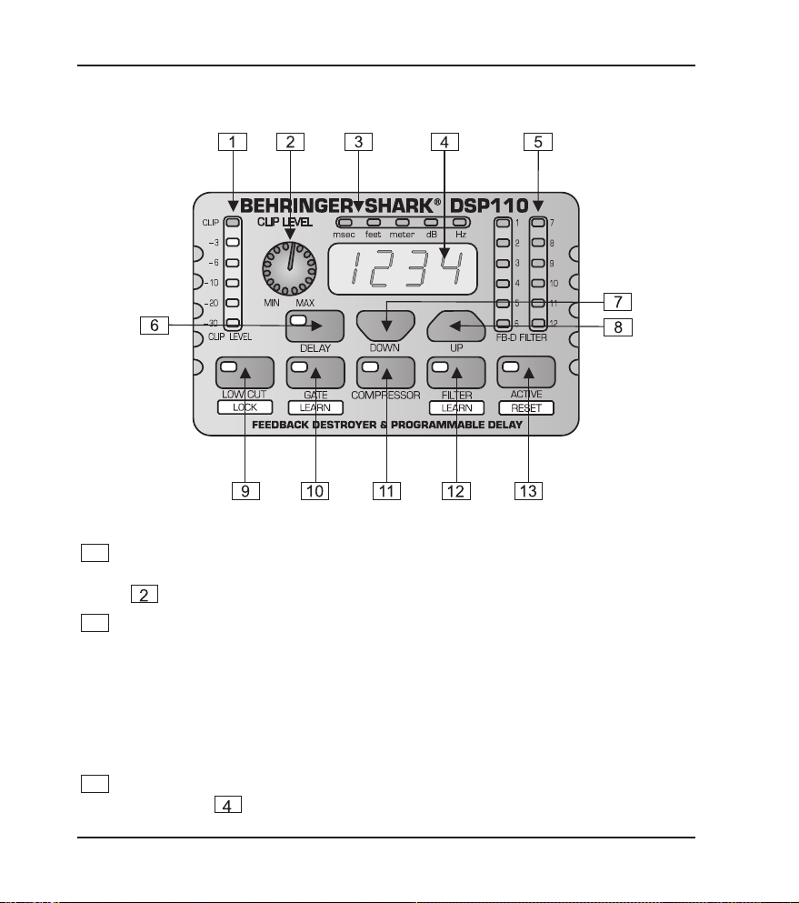
Fig. 1.2: Front panel control elements of the DSP110
1
The CLIP LEVEL METER shows you whether or not the digital circuitry is
driven correctly. Any corrections can be made with the CLIP LEVEL control
. Be sure that the CLIP LED wont light up.
2
The CLIP LEVEL control lets you adapt the internal gain optimally to the digital
circuitry. If gain is too high (CLIP LED lights up), raise the CLIP LEVEL value by
turning the control to the right (and vice versa). Thus, you can shift the operating
level upwards/downwards.
+ The CLIP LEVEL control does not affect the input/output levels, but adapts
the audio signal as optimally as possible to the threshold of the digital
circuitry.
3
These five LEDs symbolize the units of the parameters that can be adjusted on
the display
.
6
1. INTRODUCTION
Page 7

SHARK DSP110
4
The 4-digit DISPLAY reads the absolute values of the adjusted parameters.
5
The FB-D FILTER STATUS LEDs display the status of each of the 12 individual
filters. The SHARK uses four different filter modes:
s
Disabled filters (which can be re-enabled with the ACTIVE button). When a
filter is off, its LED is not lit.
Free filters which automatically search for feedback frequencies and whose
s
activity is shown by a flashing LED.
s Set filters which can be reconfigured as free (searching) filters, when all filters
are currently in use.
s
Permanently set filters which must be RESET to be reconfigured as free filters.
Once a filter has been set, its LED lights up.
6
The DELAY button allows you to adjust the Delay Line time. Press the button
several times to either choose msec, feet or meter. The last unit selected will be
stored and recalled next time you use the DELAY function. The control LED
lights up while you are making your entries. The setting range is from 0 to
2,500.0 msec, 0 to 2,818.2 feet, and 0 to 859.00 meters. When you are using
high values, the 4-digit display reads the last figure only when you start editing
with the UP/DOWN buttons. Example: for a value of 1,500.0 msec, the display
reads 1500 when you press the DELAY button, and 500.0 when you start
editing. In this way, you can use extremely small steps when editing parameters.
+ To speed up the selection, briefly press the key located next to the UP or
DOWN key. The selection speed will be increased with each additional key
press. This function can be used for all parameter edits.
7
The DOWN button lowers the parameter values shown in the display .
8
The UP button raises these parameter values.
1. INTRODUCTION
7
Page 8

SHARK DSP110
9
The LOW CUT button lets you enter the high pass filters cut-off frequency
(20 to 150 Hz). When set to OFF the filter is inoperative. The control and Hz
LEDs light up while you are entering a value. Use the UP/DOWN buttons to
edit. Pressing the LOW CUT button for a longer time (please wait, until all
five parameter LEDs light up) enables the keypad lock feature which prevents
inadvertent editing of parameters and settings. When the keypad lock is enabled,
the LOW CUT keys control LED starts flashing.
10
Use the GATE button to adjust the threshold of the internal Noise Gate (-96 dB
through -44 dB). When set to OFF, the Noise Gate is inoperative. The control
LED of the GATE button lights up while you are entering a value. Pressing the
GATE button for a longer time (please wait, until all five parameter LEDs light
up) enables the GATE LEARN function, which automatically sets the Noise
Gate threshold by analyzing the program material and adjusting the value
accordingly (value detected plus 2 dB). In GATE LEARN mode, the GATE keys
control LED starts flashing. As long as the LED flashes, the detected value is
read on the display, when the LED stops flashing, the value is raised by +2 dB.
11
The COMPRESSOR button gives you access to two parameters that let you
adapt the DSP110s Compressor function to the program material. Press the
button once to adjust the DENSITY parameter, which controls the compression
density from 0 (no processing) to 100 (maximum compression). Press the
COMPRESSOR button a second time to adjust the SPEED parameter which
controls the Compressors attack and release times from 10 to 1000 msec. The
msec LED lights up as soon as you select the SPEED parameter.
12
The FILTER key allows you to set the feedback detection sensitivity within a
range from 1 (no sensitivity) through 100 (full sensitivity). The default value is
50. The control LED lights up during data entry. Briefly press the FILTER key a
second time to edit the maximum attenuation of the FB-D filter (from -3 dB
through -48 dB in steps of 3). Pressing the FILTER key longer (please wait, until
all five parameter LEDs light up) activates the FILTER LEARN function, which
automatically searches for feedback frequencies and assigns free filters to the
frequencies found. Now you can enter the number of filters (standard: 9) to be
used for permanent feedback suppression. Although the remaining filters are
also used to eliminate feedback frequencies, they are released once new
feedback occurs. Pressing the FILTER key once again activates the FILTER
LEARN function.
8
1. INTRODUCTION
Page 9

SHARK DSP110
+ When both FILTER LED and display stop flashing, the FILTER LEARN function
has been completed. Press the FILTER key to cancel the function. After a
short delay, the unit returns to the FILTER menu.
The FILTER LEARN function generates short feedback-causing signals that
are sent back to the DSP110s input, where feedbacks are detected and
suppressed. The FILTER LEARN function is an useful tool for live concerts that
prevents filters from being released prematurely. Fixed filters can only be
reconfigured as free, searching filters by means of a RESET. In normal mode,
which is activated after power-up, set filters are automatically released one after
the other, when free filters are needed to search and destroy feedback
frequencies.
+ To ensure that the FILTER LEARN function works properly, the short
feedback-causing signals are output with a level of -18 dB below digital
maximum. However, the feedback caused during the FILTER LEARN
procedure will be limited by the compressor to -30 dB below digital
maximum. Please note that considerable volume levels can still occur,
which is why you should use the FILTER LEARN function only before the
concert/event begins.
13
Enable the ACTIVE button to set inoperative filters to automatic search mode.
When this button is up (control LED is off), those filters are inoperative which
have not yet found a feedback frequency. Pressing the ACTIVE button for a
longer time (please wait, until all five parameter LEDs light up) enables the
RESET function. All filters will be reset, i.e. set to automatic search mode.
1. INTRODUCTION
9
Page 10

SHARK DSP110
10
Page 11

SHARK DSP110
20
This is the SHARKs balanced JACK input, which is wired in parallel to the XLR
input.
21
Use the INPUT LEVEL switch to select the input sensitivity (microphone or line
levels). In LINE mode, you can use the CLIP LEVEL control to adapt the internal
level settings to the digital circuitry. Please make sure that the CLIP-LED will
not light up.
22
The PHANTOM switch enables the Phantom Power supply required for
condenser microphones.
23
The PHANTOM CONTROL LED lights up when Phantom Power is on.
2. APPLICATIONS
2.1 Wiring the DSP110: general remarks
With its great versatility the SHARK can be used for a variety of applications. This
chapter describes connection and configuration examples of the most common
applications.
2.1.1 Connection between microphone and mixing console
In live applications it is often useful to protect specific single microphones against
feedback. We therefore recommend that you connect the SHARK between your
microphone and a microphone input on your mixing console (OUTPUT LEVEL switch
set to MIC). If all mic inputs are in use, you can set the SHARKs OUTPUT switch to
+4dBu (switch pressed) and adapt the output signal of your SHARK to a line input on
your console using the MIC GAIN control. To prevent the occurrence of subsonics you
can activate the SHARKs Low Cut filter. Switch on Phantom Power when you are
using condenser microphones.
2. APPLICATIONS
11
Page 12

SHARK DSP110
12
Page 13

SHARK DSP110
2.1.3 Connection between mixing console and power amplifier
When you use the SHARK as a Delay Line unit for speaker systems placed at various
positions (see chapter 2.3), you should connect the SHARK between the consoles
output and the input of the power amp driving the delayed speakers.
13
Page 14

SHARK DSP110
2.1.4 The SHARK used in the monitor path
Inserting the DSP110 in the monitor path of your mixing console gives you utmost
protection against unwanted feedback. Monitor paths are particularly susceptible to
feedback, because on stage there are usually several microphones and speakers placed
close to each other. Especially vocal microphones pose some problems, because their
volume levels must be fairly high to be able to compete with other instruments, and
often these microphones are hand-held and hence carried around on stage. It is therefore
useful to protect the monitor path against feedback. In particular, when used in the
monitor path, the SHARK produces a positive side effect in that it improves both sound
and volume of the monitors. By filtering interference it makes the sound more transparent
and by eliminating unwanted feedback it allows for raising the volume of the monitors,
an effect that is usually welcomed by musicians on stage. Another advantage when
using this configuration: one SHARK can control several microphones. As at least four
monitor paths are used in a typical live application, all you need are four SHARKs to
give you optimum feedback protection.
14
2. APPLICATIONS
Page 15

SHARK DSP110
Fig. 2.4: Two SHARKs in the monitor path
2.1.5 The SHARK used in single channels and subgroups
Whenever you want to make sure that wanted feedback such as the feedback sounds
produced by a guitar wont be removed, you should insert one or several DSP110 into
feedback-prone single channels (e.g. vocals) or subgroups of your mixing console!
Route all channels that are susceptible to feedback (e.g. all vocal mics) to one or
several subgroups, in which you insert one or several SHARKs. In this way, all channels
that are less liable to produce feedback (e.g. those carrying line-level signals, or
instrumental microphones with lower volumes) can pass the console unaltered, while
only critical microphone channels are controlled by the DSP110. Thus, you can protect
your sound reinforcement system against feedback and still use wanted feedback
sounds.
2. APPLICATIONS
15
Page 16

SHARK DSP110
16
Page 17

SHARK DSP110
2.2 The Feedback Destroyer in the SHARK
The SHARK identifies feedback by splitting the entire frequency spectrum (20 Hz to
20 kHz) into sections of 1/60 of an octave and determining the level of each of these
bands. The values calculated are then referenced to the level of the overall signal. The
resulting level difference determines whether or not a filter is set. The SHARK allows
you to adapt these decisive parameter to your needs: within a range from 1 through
100 you can edit the feedback detection sensitivity. The standard setting is 50, which
ensures the best possible detection of feedback for the majority of applications. For
speech-only applications you can raise the feedback detection threshold towards 100,
which enables the algorithm to detect and remove feedback even more quickly. Vice
versa, lower values provide for a more stable feedback suppression responding less to
wanted feedback-like signal portions produced by guitars or keyboards.
In FILTER LEARN mode, feedback is generated and suppressed automatically.
Whenever it detects feedback, the DSP110 selects the filter parameters automatically
to efficiently remove the feedback. As the filter is set to the frequency detected, this
mode is ideally suitable for suppressing constant feedback frequencies produced by
fixed microphones, e.g. those used on drums. Once set, the filters automatically enters
lock mode, i.e. the frequency remains fixed but width and depth of the filter are still
being adapted to the signal. The filter width is enlarged whenever the feedback frequency
shifts slightly. If feedback persists, gain is reduced even more and kept low to prevent
feedback from recurring.
All microphones that are moved during a performance (e.g. hand-held vocal
microphones) are usually susceptible to varying feedback frequencies, which should
be suppressed in automatic search mode (entered when you power up the SHARK).
Much like in FILTER LEARN mode, a filter automatically determines the ideal settings
for all parameters, in order to suppress feedback. However, once all filters have been
set, the filter first activated gets reset to automatic search mode. Thus, the SHARK
makes sure that there is always one free filter to identify and remove new feedback
frequencies. If your music contains wanted feedback elements (e.g. guitar feedback),
the SHARK will suppress these too, because it is impossible from a physical point of
view to distinguish wanted from unwanted feedback. Section 2.1.6 provides some
information on how to get around this physical problem.
2. APPLICATIONS
17
Page 18

SHARK DSP110
2.3 The integrated Delay
In addition to speakers on or near the stage, major-scale installations often have
speaker groups positioned at a distance to the stage or flown above the audience, in
order to provide listeners away from the stage with direct sound. However, since
sound needs some time to travel around (343.6 m/sec at 20°C, accelerates by 0.6 m/
sec per °C), it reaches the audience not simultaneously but gets delayed by a certain
amount. To make up for the different run times between stage and remote speakers,
the latter must be provided with an electronically delayed signal, which is usually
done by means of special-purpose Delay devices. You wont need them, however,
when youve got a SHARK, as the DSP110 integrates a Delay Line circuit giving you
the same convenience of operation as dedicated devices. Simply measure the
distance between the various speaker groups and enter this value (in meters or feet).
Chapter 2.1.3 shows you how to wire the DSP110 in this type of application.
Fig. 2.6: Sound reinforcement application with different speaker positions
2.4 The Noise Gate function
The main task of a Noise Gate is to separate unwanted background noise from
wanted signals and remove noise inaudibly. A so-called downward Expander
automatically reduces the overall level of all signals below an adjustable threshold
and thus expands the dynamic range of the program material.
In live or stage applications and multi-microphone systems, in particular, the SHARK
has a variety of possible uses: as a moderately and accurately set Gate it efficiently
suppresses background noise, compressor-induced noise build-up and crosstalk
18
2. APPLICATIONS
Page 19

SHARK DSP110
between microphones, without producing any unpleasant side effects.
A typical Gate application is the processing of vocal tracks. Especially when using a
Compressor, the distance between microphone and singer is critical: as the distance
increases, more and more disturbing background noise is picked up. Use the Gate
function to fade out unwanted interference inaudibly during music pauses. In live
applications, e.g. crosstalk of drum and piano tracks can be suppressed or acoustically
contaminated recordings can be cleaned.
When a singer sings into a stage microphone, the background noise is masked and
hence not perceived. During music pauses, however, the microphone picks up the
noise produced by the P.A. system and monitor speakers, which can lead to unpleasant
feedback.
When you insert the SHARK in a vocal channel and adjust it so that it mutes the
channel, as long as the microphone is not in use, susceptibility to feedback can be
reduced enormously. Basically, all stage microphones should be treated in this way.
The GATE LEARN function helps you adjust the Gate threshold. Use this function
before the concert and after the sound check. If the adjusted value yields unsatisfactory
results, the UP/DOWN buttons can be used to fine-tune the Gate, until it closes only
during signal pauses and suppresses interference efficiently.
2.5 The Low Cut filter in the SHARK
In miking it is quite common to fade out low-frequency signal portions such as stage
rumble, pop sounds or other types of interference. Frequencies of that kind often have
high amplitudes and not only affect the sound image but can also damage power amps
and/or loudspeakers. The SHARK is equipped with a tunable high pass filter that features
a very high slope. Press the LOW CUT button to tune the cutoff frequency from 20 Hz
through 150 Hz with the UP/DOWN buttons, so that interference noise is faded out as
perfectly as possible, while the wanted signals remains unaffected.
2.6 The Compressor function
In broadcast and recording applications, signal levels often exceed the headroom of
signal-processing devices, which means that the dynamic range must be reduced to
avoid distortion. This is usually accomplished by the use of Compressors or Limiters,
which use an automatic gain control circuit to reduce the signal level during loud
passages. In this way, it is possible to compress the dynamics of a microphone channel
2. APPLICATIONS
19
Page 20

20
Page 21

SHARK DSP110
Unbalanced use of
mono 1/4" jack plugs
2 1
3
Balanced use of
stereo 1/4" jack plugs
Ring
Balanced use with XLR connectors
1 2
3
21
Page 22

SHARK DSP110
4. SPECIFICATIONS
AUDIO INPUTS
Connectors XLR and 1/4" jack
Type RF filtered, servo-balanced input
Impedance 6 kOhms balanced, 3 kOhms unbalanced
Nominal Operating Level microphone or line level source (switchable)
Max. Input Level +19 dBu at microphone level and line level
AUDIO OUTPUTS
Connectors XLR and 1/4" jack
Type electronically servo-balanced output stage
Impedance 60 Ohms balanced, 30 Ohms unbalanced
Nominal Operating Level microphone level source or +4 dBu (switchable)
Max. Output Level +20 dBu at +4 dBu nominal level, -12 dBu at microphone level
SYSTEM SPECIFICATIONS
Frequency Response 10 Hz to 21 kHz
Noise > 92 dB at line level, unweighted, 22 Hz to 22 kHz
THD 0.007 % typ. @ +4 dBu, 1 kHz, gain 1
DIGITAL PROCESSING
Converters 24-bit Sigma-Delta, 64/128-times oversampling
Sampling Rate 46.875 kHz
DISPLAY
Type 4-digit numeric LED display
POWER SUPPLY
Mains Voltages USA/Canada 120 V ~, 60 Hz, PSU DSP110UL
PHYSICAL
Dimensions (H * W * D) approx. 2 1/4" (56 mm) x 3 1/2" (88 mm) x 5 1/8" (130 mm)
Net Weight approx. 0.5 kg
> 89 dB at microphone level, unweighted, 22 Hz to 22 kHz
U.K./Australia 240 V ~, 50 Hz, PSU DSP110UK
Europe 230 V ~, 50 Hz, PSU DSP110EU
Japan 100 V ~, 60 Hz, PSU DSP110JP
General export model 100 - 120 V ~, 200 - 240 V ~, 50 - 60 Hz
BEHRINGER is constantly striving to maintain the highest professional standards. As a result of these efforts,
modifications may be made from time to time to existing products without prior notice. Specifications and appearance
may differ from those listed or illustrated.
22
4. SPECIFICATIONS
Page 23

SHARK DSP110
5. RACKMOUNT (OPTIONAL)
With the available rackmount (optional) you have the possibility to place five SHARKs
on two units of space in your rack.
+ Before you begin with the work, please disconnect the Power Supply Units
from the SHARKs!
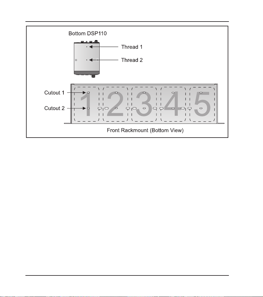
To mount the SHARKs on the rackmount you should use the supplied screws (type
M3). You need two screws to fix one DSP110 onto the rackmount. In the bottom of your
SHARK you will find two little threads. You have to position the single SHARKs on the
rackmount, so that the threads correspond to the cutouts of the rackmount (see fig.5.1).
Now you can fix the DSP110 onto the rackmount. Just take a cross-point screwdriver
and tighten both screws loosely. After you have fixed all SHARKs on the rackmount,
you can adjust the devices and tighten all screws solidly.
5. RACKMOUNT (OPTIONAL)
23
Page 24
SHARK DSP110
Fig. 5.1: Installation of the DSP110 on the available rackmount (optional)
+ Please, only use the supplied screws to install the SHARKs on the
rackmount. Longer or thicker screws can damage the electronics inside
of the device and doing so will void your warranty rights.
You will need 2 units of space for the DSP110 rackmount. For technical reasons a little
gap remains above the rackmount.
24
5. RACKMOUNT (OPTIONAL)
Page 25

SHARK DSP110
not cover any such modification/adaptation, irrespective of whether it
6. WARRANTY
§ 1 WARRANTY CARD/ONLINE REGISTRATION
To be protected by the extended warranty, the buyer must complete
and return the enclosed warranty card within 14 days of the date of
purchase to BEHRINGER Spezielle Studiotechnik GmbH, in accordance
with the conditions stipulated in § 3. Failure to return the card in due
time (date as per postmark) will void any extended warranty claims.
Based on the conditions herein, the buyer may also choose to use the
online registration option via the Internet (www.behringer.com or
www.behringer.de).
§ 2 WARRANTY
1. BEHRINGER (BEHRINGER Spezielle Studiotechnik GmbH including
all BEHRINGER subsidiaries listed on the enclosed page, except
BEHRINGER Japan) warrants the mechanical and electronic
components of this product to be free of defects in material and
workmanship for a period of one (1) year from the original date of
purchase, in accordance with the warranty regulations described below.
If the product shows any defects within the specified warranty period
that are not due to normal wear and tear and/or improper handling by
the user, BEHRINGER shall, at its sole discretion, either repair or replace
the product.
2. If the warranty claim proves to be justified, the product will be returned
to the user freight prepaid.
3. Warranty claims other than those indicated above are expressly
excluded.
§ 3 RETURN AUTHORIZATION NUMBER
1. To obtain warranty service, the buyer (or his authorized dealer) must
call BEHRINGER (see enclosed list) during normal business hours
BEFORE returning the product. All inquiries must be accompanied by a
description of the problem. BEHRINGER will then issue a return
authorization number.
2. Subsequently, the product must be returned in its original shipping
carton, together with the return authorization number to the address
indicated by BEHRINGER.
3. Shipments without freight prepaid will not be accepted.
§ 4 WARRANTY REGULATIONS
1. Warranty services will be furnished only if the product is accompanied
by a copy of the original retail dealers invoice. Any product deemed
eligible for repair or replacement by BEHRINGER under the terms of
this warranty will be repaired or replaced within 30 days of receipt of the
product at BEHRINGER.
2. If the product needs to be modified or adapted in order to comply with
applicable technical or safety standards on a national or local level, in
any country which is not the country for which the product was originally
developed and manufactured, this modification/adaptation shall not be
considered a defect in materials or workmanship. The warranty does
The information contained in this manual is subject to change without notice. No part of this manual may be reproduced or transmitted in any form or by
any means, electronic or mechanical, including photocopying and recording of any kind, for any purpose, without the express wri tten permission of
BEHRINGER, SHARK and FEEDBACK DESTROYER are registered trademarks. ALL RIGHTS RESERVED.
BEHRINGER Spezielle Studiotechnik GmbH, Hanns-Martin-Schleyer-Str. 36-38, 47877 Willich-Münchheide II, Germany
BEHRINGER Spezielle Studiotechnik GmbH.
© 2001 BEHRINGER Spezielle Studiotechnik GmbH.
Tel. +49 (0) 21 54 / 92 06-0, Fax +49 (0) 21 54 / 92 06-30
was carried out properly or not. Under the terms of this warranty,
BEHRINGER shall not be held responsible for any cost resulting from
such a modification/adaptation.
3. Free inspections and maintenance/repair work are expressly excluded
from this warranty, in particular, if caused by improper handling of the
product by the user.
This also applies to defects caused by normal wear and tear, in particular,
of faders, potentiometers, keys/buttons and similar parts.
4. Damages/defects caused by the following conditions are not covered
by this warranty:
s misuse, neglect or failure to operate the unit in compliance with
the instructions given in BEHRINGER user or service manuals.
s connection or operation of the unit in any way that does not comply
with the technical or safety regulations applicable in the country
where the product is used.
s damages/defects caused by force majeure or any other condition
that is beyond the control of BEHRINGER.
5. Any repair or opening of the unit carried out by unauthorized personnel
(user included) will void the warranty.
6. If an inspection of the product by BEHRINGER shows that the defect
in question is not covered by the warranty, the inspection costs are
payable by the customer.
7. Products which do not meet the terms of this warranty will be repaired
exclusively at the buyers expense. BEHRINGER will inform the buyer
of any such circumstance. If the buyer fails to submit a written repair
order within 6 weeks after notification, BEHRINGER will return the unit
C.O.D. with a separate invoice for freight and packing. Such costs will
also be invoiced separately when the buyer has sent in a written repair
order.
§ 5 WARRANTY TRANSFERABILITY
This warranty is extended exclusively to the original buyer (customer of
retail dealer) and is not transferable to anyone who may subsequently
purchase this product. No other person (retail dealer, etc.) shall be entitled
to give any warranty promise on behalf of BEHRINGER.
§ 6 CLAIM FOR DAMAGES
Failure of BEHRINGER to provide proper warranty service shall not
entitle the buyer to claim (consequential) damages. In no event shall
the liability of BEHRINGER exceed the invoiced value of the product.
§ 7 OTHER WARRANTY RIGHTS AND NATIONAL LAW
1. This warranty does not exclude or limit the buyers statutory rights
provided by national law, in particular, any such rights against the seller
that arise from a legally effective purchase contract.
2. The warranty regulations mentioned herein are applicable unless they
constitute an infringement of national warranty law.
6. WARRANTY
25
 Loading...