

Page 1

®
IMMAGE® 800
Immunochemistry System
A11409-AA
March 2004
REPEC
Beckman Coulter Ireland, Inc.
Mervue Business Park,
Mervue Galway,
Ireland 353 91 774068
BECKMAN COULTER, INC. • 4300 N. Harbor Blvd., Fullerton, CA U.S.A. 92835
Instructions For Use
For In Vitro Diagnostic Use
© Copyright 2004 Beckman Coulter, Inc.
Page 2

TABLE OF CONTENTS
CHAPTER 1 General Information ..................................................................................................... 1-1
Introduction ............................................................................................................... 1-1
Precautions And Hazards .......................................................................................... 1-3
CHAPTER 2 System Description ...................................................................................................... 2-1
System Description ................................................................................................... 2-1
System Specifications and Characteristics .................................................................. 2-4
Instrument Specifications ......................................................................................... 2-4
Sample Container Information ..................................................................................... 2-6
Sample Containers Allowed ..................................................................................... 2-6
CHAPTER 3 Theory of Operations ................................................................................................... 3-1
Principles of Methodologies ..................................................................................... 3-1
Antigen Excess Testing ............................................................................................ 3-2
CHAPTER 4 System Power On/Off .................................................................................................. 4-1
System Power On ...................................................................................................... 4-1
System Power Off ..................................................................................................... 4-2
CHAPTER 5 System Software Configuration ................................................................................... 5-1
Overview ................................................................................................................... 5-1
Selecting Non-Standard Dilutions as Default for Each Chemistry ........................... 5-6
User-Defined Reagent Chemistry Setup .................................................................... 5-10
UDR Chemistry Overview and Precautions ........................................................... 5-10
Setting Up a UDR Chemistry ................................................................................. 5-11
Defining a UDR Chemistry .................................................................................... 5-16
Defining UDR Calibration Information .................................................................. 5-25
Deleting UDR Chemistries ..................................................................................... 5-26
Editing UDR Definitions ........................................................................................ 5-27
Loading UDR Reagent Cartridges .......................................................................... 5-29
Loading/Clearing UDR Buffer and Diluent ............................................................ 5-32
Programming Rate Mode ........................................................................................ 5-34
Calibrating a UDR Chemistry ................................................................................. 5-37
Approving a Calibration ......................................................................................... 5-44
Printing UDR Reports ............................................................................................. 5-54
Setting Up UDR Reference Intervals and Panels ................................................... 5-56
Defining UDR Quality Control ............................................................................... 5-57
Programming a UDR Sample ................................................................................. 5-58
Instrument Setup ........................................................................................................ 5-59
Overview ................................................................................................................. 5-59
Placing Labels on a Rack ........................................................................................ 5-60
Wash Solution Box and Waste Container Placement ............................................. 5-61
IMMAGE 800 Instructions For Use A11409 Table of Contents
March 2004 Page 1 of 2
Page 3

CHAPTER 6 Reagents/Calibration .................................................................................................... 6-1
Reagents .......................................................................................................................6-1
Overview ................................................................................................................... 6-1
Calibration ................................................................................................................... 6-6
Overview ................................................................................................................... 6-6
Calibration History ................................................................................................... 6-8
CHAPTER 7 Preparing for Programming/Running .......................................................................... 7-1
Overview ................................................................................................................... 7-1
Programming a Sample ................................................................................................ 7-3
Overview ................................................................................................................... 7-3
Selecting Sample Options ......................................................................................... 7-6
Entering an Off-line Dilution Factor ........................................................................ 7-8
Programming a Batch of Samples .......................................................................... 7-12
Loading and Starting a Run ....................................................................................... 7-15
Loading Samples ..................................................................................................... 7-15
Pre-run Checklist .................................................................................................... 7-17
Starting the Run ...................................................................................................... 7-18
Pausing a Run ............................................................................................................ 7-19
Overview ................................................................................................................. 7-19
System Pause .......................................................................................................... 7-20
Pausing to Load Samples ........................................................................................ 7-21
CHAPTER 8 Results Recall .............................................................................................................. 8-1
Overview ................................................................................................................... 8-1
Displaying Recalled Results on the Screen .............................................................. 8-2
Printing Recalled Results .......................................................................................... 8-3
Sending Results to the Host ...................................................................................... 8-4
CHAPTER 9 Quality Control ............................................................................................................ 9-1
Overview ................................................................................................................... 9-1
Defining a Control .................................................................................................... 9-2
CHAPTER 10 Utilities ....................................................................................................................... 10-1
Maintenance ............................................................................................................ 10-1
Troubleshooting ...................................................................................................... 10-3
CHAPTER 11 System Status/Instrument Commands ....................................................................... 11-1
System Status/Instrument Commands .................................................................... 11-1
APPENDIX A Additional Information ............................................................................................... A-1
Pre-run Checklist ..................................................................................................... A-1
Quick References Using the IMMAGE 800 Immunochemistry System Operations
Manual ..................................................................................................................... A-2
INDEX
IMMAGE 800 Instructions For Use A11409 Table of Contents
March 2004 Page 2 of 2
Page 4

Introduction
Intended Use
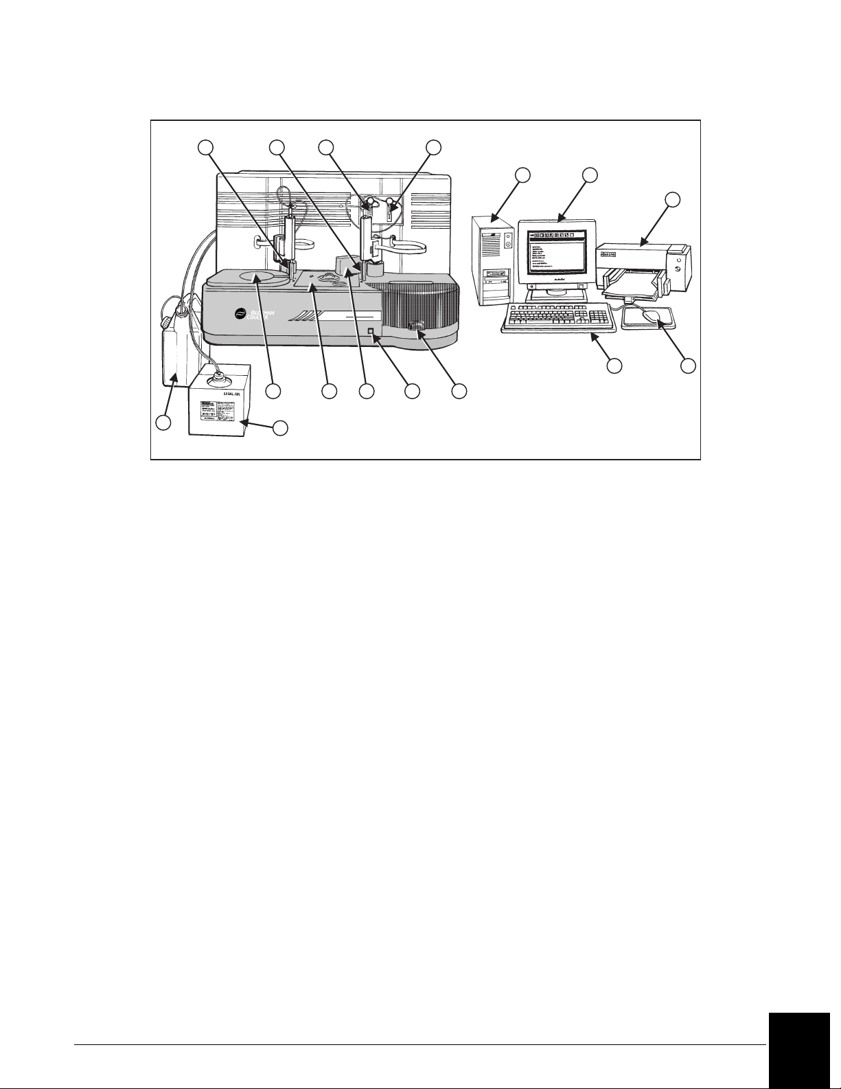
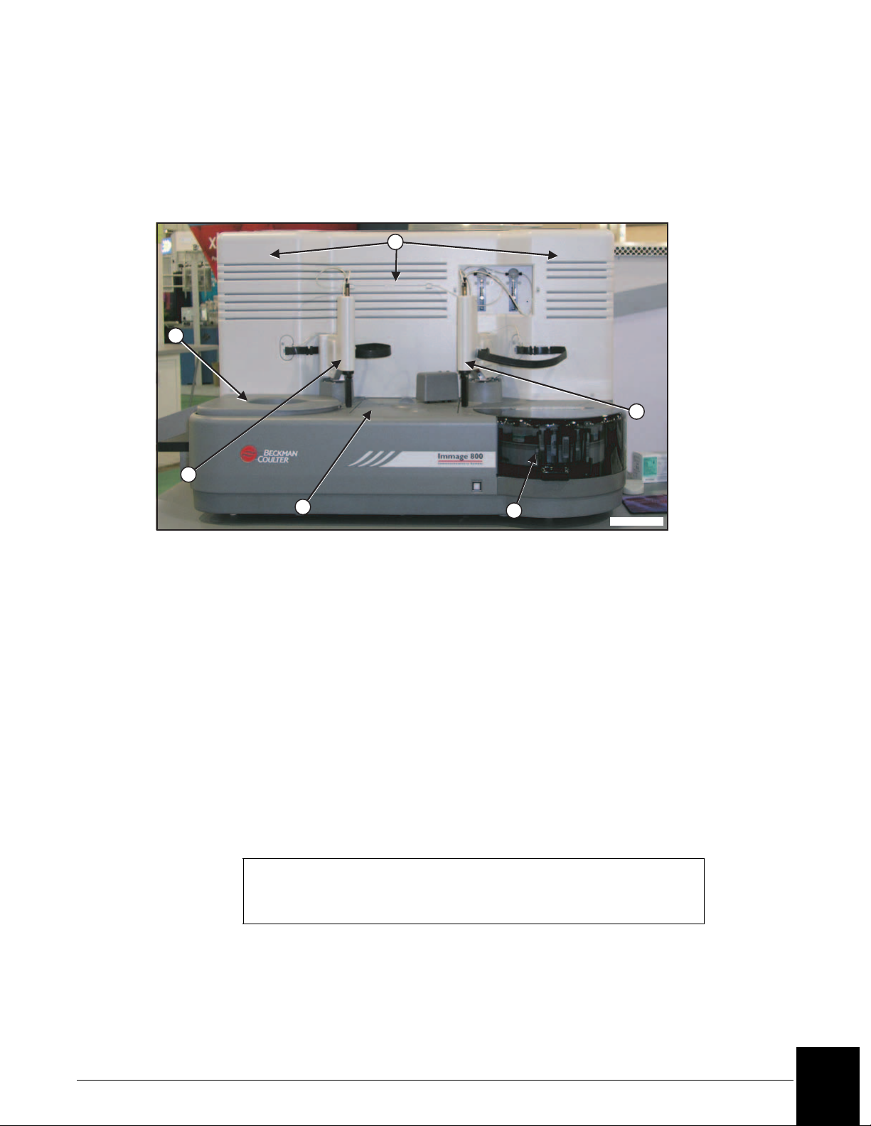
The Beckman Coulter IMMAGE® 800 Immunochemistry System (Refer to Figure 1.1.) is a
fully automated, computer controlled, bench-top analyzer designed for the in vitro
quantitation of biological fluid components and therapeutic drugs. The system methodologies
are rate turbidimetry and rate nephelometry.
The IMMAGE 800 is a high throughput, random access analyzer that features bar code
identification of samples and reagents to perform sample testing. It automatically dilutes the
samples and delivers them to the reaction cuvette along with other reaction constituents. The
system analyzes up to 72 samples per run with up to 24 analytes per sample.
Scope of Manual
This manual provides information on the operation of the IMMAGE 800. Diagnostic
interpretation or the clinical significance of the assay results provided by the system are not
discussed in this manual. Typical and actual results are shown only to demonstrate the
operating procedures, parameters, and characteristics of the system.
CHAPTER 1 General Information
Reference Materials
Detailed information is available in the following manuals that accompany the IMMAGE 800
Immunochemistry System. Those manuals include:
• IMMAGE 800 Immunochemistry System Operations Manual. This manual contains a
detailed system description, comprehensive operating instructions, theory of operation,
system calibration and programming procedures, and quality control information for the
IMMAGE 800 analyzer.
• IMMAGE Immunochemistry Systems Chemistry Information Manual. This manual
contains specific chemistry information for the full range of analytes available on the
IMMAGE 800 analyzer.
• IMMAGE Immunochemistry Systems Host Interface Specifications.
• IMMAGE Immunochemistry Systems Sampling Template.
IMMAGE 800 Instructions For Use A11409 General Information
March 2004 Page 1-1
1
Page 5
1 2 3 4
5 6
7
8
1. Reagent Probe and Mixer
2. Sample Probe and Mixer
3. Reagent Syringe
4. Sample Syringe
5. Computer
6. Monitor
7. Printer
8. Waste Container
9. Wash Solution
Figure 1.1 IMMAGE 800 Immunochemistry System
Shipping Damage
Each IMMAGE 800 System is carefully examined and checked by Beckman Coulter before it
is shipped. When you receive your new IMMAGE 800 System, visually inspect the shipping
container for any possible damage, It there is damage, notify the Beckman Coulter Service
Representative before his/her arrival at your facility to install your system.
®
9
Immage 800
11 12
141310
10. Reagent Compartment
11. Reaction Module
12. Cuvette Wash Station
13. Advance Button
14. Sample Carousel
15. Keyboard
16. Mouse
17. Uninterruptible Power Supply
-not shown
15
16
A011426L.EPS
If no damage is found to the shipping container, the Beckman Coulter Service Representative
will supervise the unpacking of your system. If there is damage in any way, the customer
should file a claim with the carrier. If no damage is found, a visual and operational check of
your system will be performed.
IMMAGE 800 Instructions For Use A11409 General Information
March 2004 Page 1-2
1
Page 6

Precautions And Hazards
Precautions
• Do not store or place a diskette near electrical motors, power supplies, generators, magnets,
or magnetic fields.
• Hold a compact disk (CD) by the edges and replace it in its case after use. DO NOT place a
CD in direct sunlight or excessive heat or humidity.
• Sample containers must contain an adequate volume of test specimen to ensure accurate
aspiration.
Hazards
• Connect the three-pronged power plug from all system components of the IMMAGE 800
Immunochemistry System to a three-wire grounded power source. DO NOT use an adapter
to connect the power plug to a two-pronged outlet. If the electrical outlet will not accept the
three-pronged plug, notify a qualified maintenance personnel.
UNDER ANY CIRCUMSTANCES, DO NOT OPERATE THE SYSTEM UNTIL AN
ELECTRICAL GROUND IS PROVIDED AND THE POWER CORD IS PROPERLY
CONNECTED TO GROUND.
• Close reagent and sample carousel covers and keep clear of all mechanical assemblies when
booting up the system.
• Keep clear of both cranes while the instrument is running.
• Keep all covers and shields in place while the instrument is running.
• Confirm that the instrument status is Standby when adding or changing reagents, buffers,
diluents, or dilution segments. The instrument status must be in Standby or "Pausing-OK to
load samples" when adding or removing samples. Keep reagent and sample carousel covers
closed while the instrument is running.
• Confirm that the system is turned off before replacing any defective mechanical or electrical
part in the system.
• DO NOT tamper with or remove the housing of any bar code reader.
• Dispose all waste liquids from the IMMAGE 800 Immunochemistry System in an approved
method for handling biohazardous material.
• Observe all laboratory policies or procedures pertaining to the handling of biological
samples that may contain pathogens.
•To EMERGENCY STOP, turn the instrument main power switch off if the stop button on
the screen is unavailable, and the instrument must be stopped immediately.
• PRESERVATIVES: Sodium azide preservative may form explosive compounds in metal
drain lines. See National Institute for Occupational Safety and Health bulletin: Explosive
Azide Hazards (8/16/76).
• Incineration of used reagent cartridges may produce toxic fumes.
IMMAGE 800 Instructions For Use A11409 General Information
March 2004 Page 1-3
1
Page 7
Symbols and Labels
High Voltage-Electric Shock Risk
This symbol indicates high voltage or risk of electric shock.
Read Manual
This symbol cautions that the manual should be read before using the system.
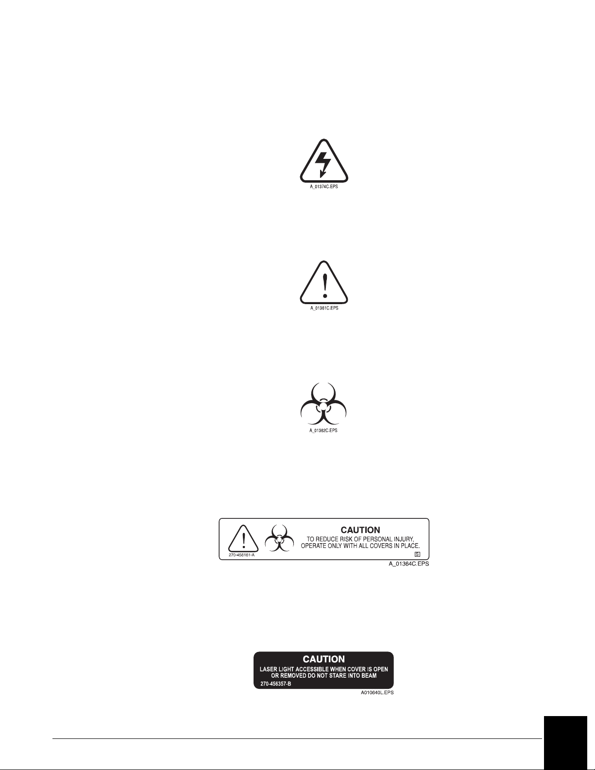
General Biohazard Caution
This symbol is the international symbol for biohazardous material.
High Voltage-Electric Shock Risk
Read Manual
Biohazard Label
Caution Biohazard
This cautionary label is located between the sample and reagent carousels. Operate the
system with all covers in place.
Caution Biohazard Label
Barcode Caution Label
This label is placed on the cover of any laser-based bar code reader. Do not stare into laser
light beam when cover is open or removed.
Bar Code Caution Label
IMMAGE 800 Instructions For Use A11409 General Information
March 2004 Page 1-4
1
Page 8
Laser
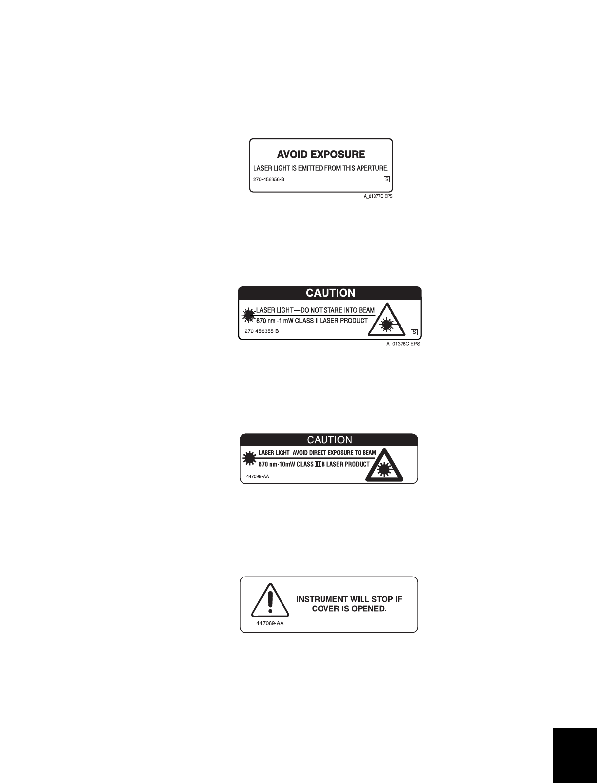
This label is placed near any opening through which a bar code reading beam emits. Avoid
exposure to laser light emitted from the opening.
Laser Caution Label
Class II Laser Caution
This cautionary label is located between the sample and reagent carousels. Do not stare into
laser light beam.
Class II Laser Caution Label
Class III B Laser Caution
This cautionary label is located at the top of the optics module. Avoid direct exposure to laser
light beam.
A010648L.EPS
Class III B Laser Caution Label
Compartment Cover Notice
This label is located on the reagent compartment cover. The instrument will stop if the cover
is opened.
A010647L.EPS
Reagent Compartment Cover Label
IMMAGE 800 Instructions For Use A11409 General Information
March 2004 Page 1-5
1
Page 9
System Description
Introduction
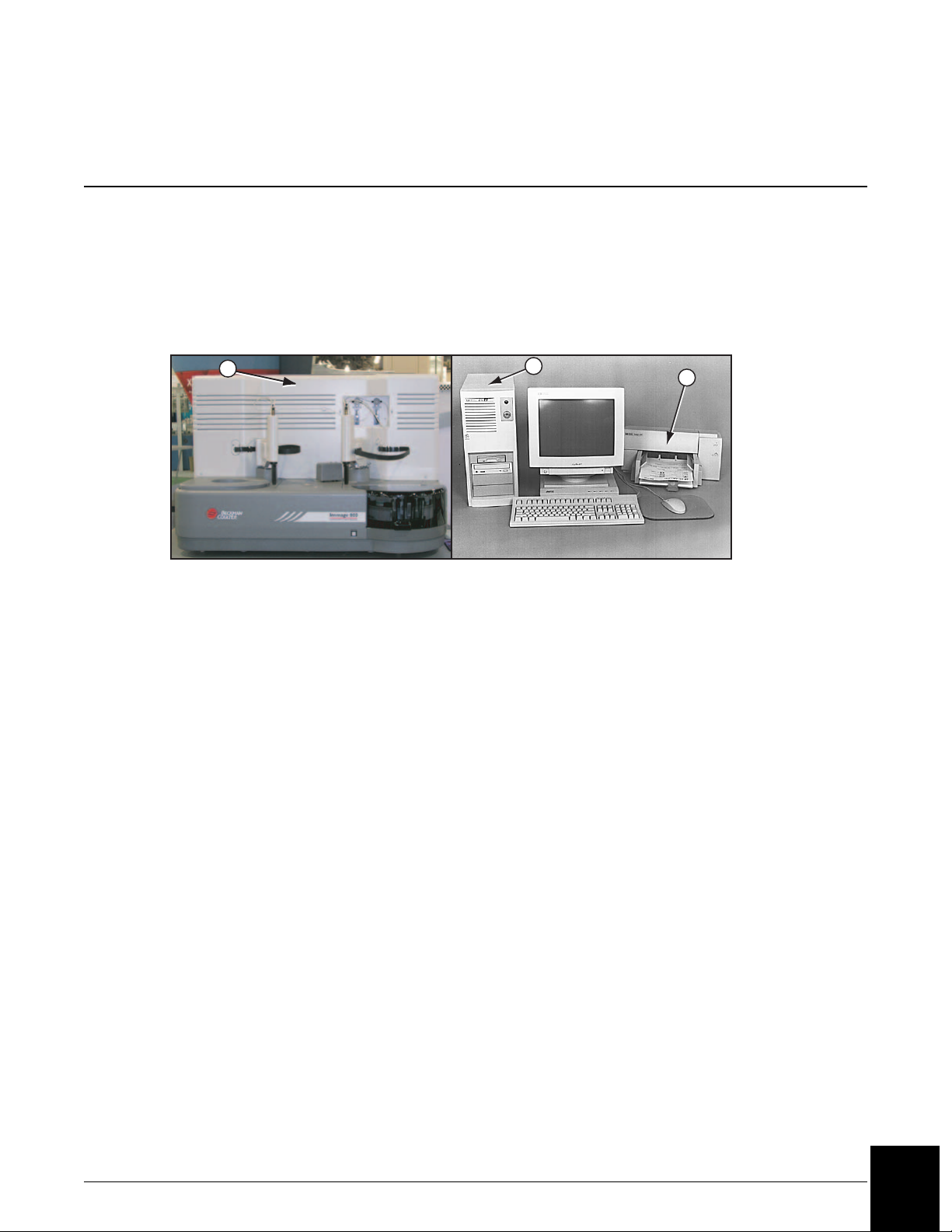
The IMMAGE® 800 Immunochemistry System is a bench-top analyzer composed of the
IMMAGE 800 instrument, computer and printer. (Refer to Figure 2.1.) The system is shipped
complete for installation. The system will be installed by a Beckman Coulter Representative.
CHAPTER 2 System Description
1
1. Instrument
2. Computer
3. Printer
2
Figure 2.1 The IMMAGE 800 Immunochemistry System
3
A011408P.EPS
IMMAGE 800 Instructions For Use A11409 System Description
March 2004 Page 2-1
2
Page 10
System Components
IMMAGE 800 Instrument
The IMMAGE 800 instrument is the analytical unit where the samples and reagents are loaded
and where the chemical reactions take place. (Refer to Figure 2.2.)
1
2
6
5
1. Reagent Compartment
2. Reagent Crane
3. Reaction Module
4. Sample Carousel
3
5. Sample Crane
6. Upper Instrument Subsystems
7. Sample Carousel Advance Button
4
A011409P.EPS
Figure 2.2 IMMAGE 800 Instrument
Computer
The computer supplies the user interface to the IMMAGE 800 Immunochemistry System and
stores data.
The user performs all software interaction in the computer portion of the system. This
software interaction is stored in the computer and is sent to the instrument at the appropriate
time.
Additionally, patient results, control results, and setup parameters are stored in the computer.
NOTICE
Only the computer supplied by Beckman Coulter is to be used with the
IMMAGE 800 Immunochemistry System.
IMMAGE 800 Instructions For Use A11409 System Description
March 2004 Page 2-2
2
Page 11
Changing the Date on the PC
The PC supplied with some IMMAGE 800 system contains a battery that provides power to
the computer’s internal clock during power off. The status of the battery is checked every time
the Power On sequence is performed.
Printer
The printer supplied with the IMMAGE 800 Immunochemistry System is a Hewlett Packard
DeskJet printer. The printer is designed to use single sheet paper.
The printer is set up to use 8.5 × 11 inch paper. Paper size can be chosen in Printer Setup.
Program Structure
The software or interface of the IMMAGE 800 Immunochemistry System is divided into
functional areas based on different tasks. The icons in the menu bar at the top of the screen
represent the various functional areas.
CAUTION
The date and time must be reset each time the Power On sequence is
performed on a computer with a dead CMOS (Complementary Metal Oxide
Semiconductor) battery. Contact Beckman Coulter Clinical Support or the
nearest local Beckman Coulter Field Service office for assistance in
replacing the battery.
The MAIN operator screen consists of:
• Stop - Instrument stops immediately
• Home - Reagents, sample carousels, cuvettes and probes return to the home position
• Pause - Instrument stops after current samples are completed
• Run - Starts a run
IMMAGE 800 Instructions For Use A11409 System Description
March 2004 Page 2-3
2
Page 12

System Specifications and Characteristics
Instrument Specifications
Placement
The surface on which the unit rests must be free of vibration and must be level, 1° or <0.75
inch (1.9 cm) slope across the length and the width of the instrument. Do not place instrument
in direct sunlight or drafts or near a heating or cooling duct.
Clearance
Sides: 6 inches (15.2 cm) minimum
Back: None
Front: 3 inches (7.6 cm) minimum
Top: 4 inches (10.1 cm) from top of instrument
Dimensions (Excluding Wash and Waste Bottles)
Height = 30 inches (76.2 cm)
Depth = 25.5 inches (64.8 cm)
Length = 43.5 inches (110.5 cm)
Weight
250 lb. (120 kg)
Power Requirements
Operating Range 115 (90 to 132) VAC RMS, Single Phase
Frequency 50/60 Hz nominal (47 to 63 Hz)
Transient Suppression Recommended
BTU Generated 2,900 BTU/hour
Electrical Outlet Grounded per Local Code
Surge Protector Recommended
Current 8.0 Amps (normal) 12 Amps surge
230 (180 to 264) VAC RMS, Single Phase
IMMAGE 800 Instructions For Use A11409 System Description
March 2004 Page 2-4
2
Page 13

Temperature and Humidity
Ambient Temperature +15°C to +32°C
Ambient Relative Humidity
(RH)
Reagent Compartment
Temperature
Reaction Module
Temperature
Environmental Conditions
System can operate up to 8000 ft (2,438m) elevation.
Drain Requirements
Flow Rate: 3 Liters/hour minimum
Waste Container Placement: The opening should be no higher than the top of the instrument.
Regulatory Agency Approvals
The IMMAGE 800 meets the safety requirements for the following agencies: CE, UL, CSA,
IEC and CENFLEC.
Environmental Conditions
System can operate up to 8000 ft. (2,438m) elevation.
15% to 85% (non-condensing)
+13°C to +22°C (+32°C Ambient, <45% RH)
+37°C ± 0.5°C
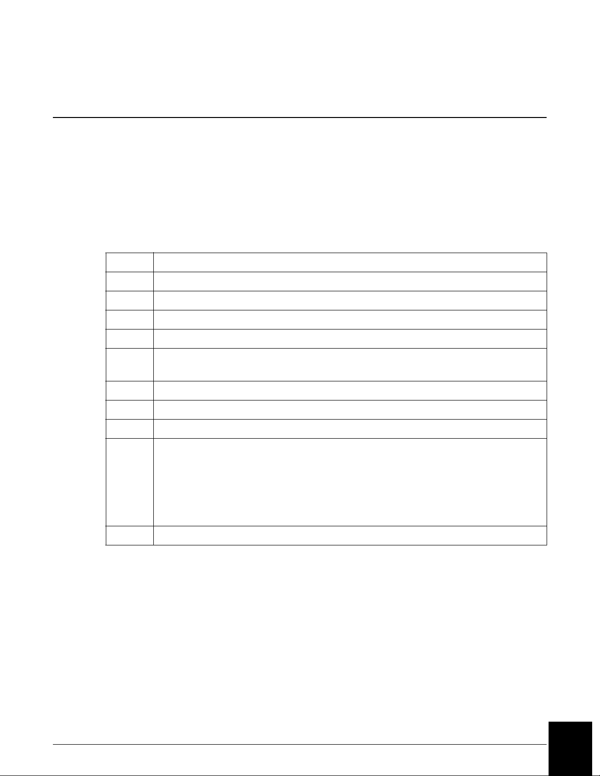
Capacities
The following table lists various system capacities.
Table 2.1 System Capacities
Item Capacity
Reagents 24 reagent cartridges can be loaded.
Reagent cartridge 40, 150, or 300 tests per cartridge.
Reaction buffers 4 bottles can be loaded.
Buffer bottle 120 mL: 350 tests.
Samples 72 samples can be loaded.
Sample diluents 4 bottles can be loaded.
Diluent bottles 120 mL: number of dilutions is workload dependent.
Sample dilution segments 4 segments of 36 wells each.
Dilution well 300 µL.
(1 of 2)
IMMAGE 800 Instructions For Use A11409 System Description
March 2004 Page 2-5
2
Page 14

Table 2.1 System Capacities, continued
Item Capacity
Wash solution 1 box/10 L/approximately 1,000 tests.
Waste container 5 gallons (18.9 L).
(2 of 2)
IMMAGE 800 Instructions For Use A11409 System Description
March 2004 Page 2-6
2
Page 15

Sample Container Information
Sample Containers Allowed
Introduction
The following categories document specifications for sample containers that can run on the
IMMAGE 800 Immunochemistry System.
Primary Tubes
16 × 100 mm (10 mL)
16 × 75 mm (7 mL)
13 × 100 mm (7 mL)
13 × 75 mm
16.5 × 92 mm
Secondary (Aliquot) Tubes
16 × 100 mm
16 × 75 mm
13 × 100 mm
12 × 75 mm
Microtubes
13 × 100 mm SYNCHRON® Microtube
Sample Cups
2 mL (placed into a sample cup holder)
0.5 mL (placed into a sample cup holder)
™
NOTICE
Low humidity and high ambient temperature may cause evaporation when
using small volumes of sample in sample cups. To minimize evaporation:
• Program samples in positions A or B on the sample carousel, or
• Program samples as STATS.
IMMAGE 800 Instructions For Use A11409 System Description
March 2004 Page 2-7
2
Page 16
CHAPTER 3 Theory of Operations
Principles of Methodologies
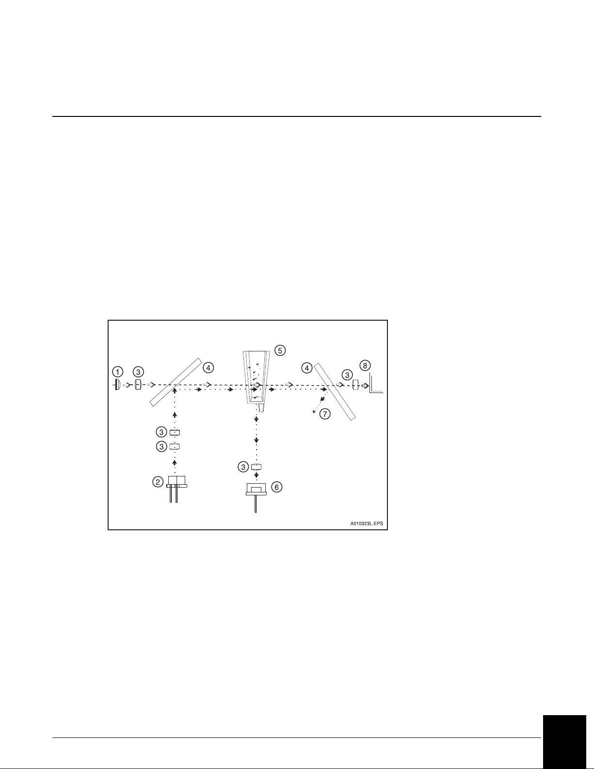
Principles of Rate Nephelometry
The rate nephelometer measures the increase in the intensity of light scattered by particles
suspended in a cuvette. The light source for the rate nephelometer is a 670 nm laser. The
detector is placed at a 90° angle from the laser beam to measure light scatter, as shown in
Figure 3.1.
Principles of Rate Turbidimetry
The rate turbidimeter measures the decrease in the intensity of light as it passes through a
solution of light scattering particles in a cuvette. The light source for the rate turbidimeter is a
light emitting diode (LED) at a wavelength of 940 nm. Turbidimetric measurements are made
at 0° from the incident beam as shown in Figure 3.1.
1. LED Light Source (Turbidimetric)
2. Laser Light Source (Nephelometric)
3. Focus Lens
4. Beam Splitter
5. Reaction Cuvette
6. Nephelometric Detector
(90° angle to incident laser beam)
7. Laser Light Bounces Into Light Trap
8. Turbidimetric Detector
(0° angle to the incident LED beam)
Figure 3.1 IMMAGE 800 Rate Nephelometer and Rate Turbidimeter Basic Components
IMMAGE 800 Instructions For Use A11409 Theory of Operations
March 2004 Page 3-1
3
Page 17

Antigen Excess Testing
Overview
Antigen excess (AGXS) testing is only necessary for some IMMAGE 800 protein reagents.
Immunoglobulin G (serum IGG, urine IGU), Immunoglobulin A (IGA), Immunoglobulin M
(IGM), Kappa (KAP), Lambda (LAM), Haptoglobin (HPT), Urine Transferrin (TRU),
Alpha-1-Microglobulin (A1M), Microalbumin (MA) and Albumin (ALB) which are
identified by the system as ambiguous, are tested for antigen excess condition if AGXS testing
is enabled. A reaction is ambiguous if the rate response could represent either an antigen
excess or an antibody excess reaction.
Antibody Excess
When the reaction is to the left of the optimal antibody-antigen proportions the reaction is in
antibody excess (AbXS). This indicates all the antigen in the sample is bound, forming
complexes. This is the ideal condition for the reaction to take place.
Antigen Excess
When the reaction is to the right of the optimal antigen-antibody proportions the reaction is in
antigen excess (AgXS) and the rate response will start to decrease due to excessive levels of
antigen.
IMMAGE 800 Instructions For Use A11409 Theory of Operations
March 2004 Page 3-2
3
Page 18
System Power On
Introduction
After the IMMAGE® 800 Immunochemistry System installation, the system can be powered
on.
Power On Sequence
Follow the steps below to power on the IMMAGE 800 system.
Step Action
1 Check that the floppy disk drive is empty.
2 Turn on the printer.
3 Turn on the monitor.
4 Turn on the CPU.
5 Verify that the UPS is on. (The UPS power switch is on and the power indicator
CHAPTER 4 System Power On/Off
light is on.)
6 Turn on the instrument.
7 Close reagent and sample carousel covers.
8 When the note is displayed to check dilution segment status, select <OK>.
9 When the temperature warning note displays, select <OK>.
• The system will continue to bring the reagent chamber and reaction cuvettes to
the appropriate temperature range.
• The system will not allow a run to start until the reaction cuvettes are within the
appropriate temperature range.
10 Refer to the appropriate chapters in this manual to operate the system.
IMMAGE 800 Instructions For Use A11409 System Power On/Off
March 2004 Page 4-1
4
Page 19

System Power Off
Power Off Sequence
The instrument status must be Standby in order to proceed with the steps below to power off
the IMMAGE 800 system.
Step Action
1 Check that the floppy diskette drive is empty.
2Select Utilities from the menu bar.
3Select <Shutdown>.
4 When the message Shutdown Complete is displayed, turn off the printer, monitor,
Emergency Stop
Turn the instrument main power switch off if the stop button on the screen is unavailable and
the instrument must be stopped immediately.
NOTICE
The database may become corrupted if power is turned off before the Power
Off sequence is completed.
CPU (computer), UPS, and instrument.
NOTICE
When an emergency stop or unplanned power loss occurs during a run, and
power is restored within 24 hours, the cuvettes must be washed 1 time before
a run can be started. (Refer to IMMAGE 800 Immunochemistry System,
Operations Manual, Chapter 10, Utilities, As-Indicated Maintenance, "Washing
Cuvettes.")
If power is restored after 24 hours, the cuvettes must be replaced. (Refer to
IMMAGE 800 Immunochemistry System Operations Manual, Chapter 10,
Utilities, As-Indicated Maintenance, "Replacing Cuvettes.")
IMMAGE 800 Instructions For Use A11409 System Power On/Off
March 2004 Page 4-2
4
Page 20

Overview
Introduction
CHAPTER 5 System Software Configuration
In System Setup several features of the IMMAGE® 800 Immunochemistry System interface
can be customized for the individual laboratory’s requirements. Setup maintains the default
parameters used for configuring the IMMAGE 800 interface. The instrument must be in
Standby in order to proceed.
This chapter includes:
• configure the chemistry menu
• set up panels
• set up bar codes
• set up reference intervals
• set up reports
• set up special calculations
• set up units/non-standard dilutions
• configure antigen excess testing
• set up date and time
• set up host communications
• set up default
• set up sample comments
• set up demographics
• set up the printer
• set up the language
• read the chemistry protocol diskette
• enter the instrument serial number
• set up user-defined reagent chemistries
IMMAGE 800 Instructions For Use A11409 System Software Configuration
March 2004 Page 5-1
5
Page 21
Accessing Setup
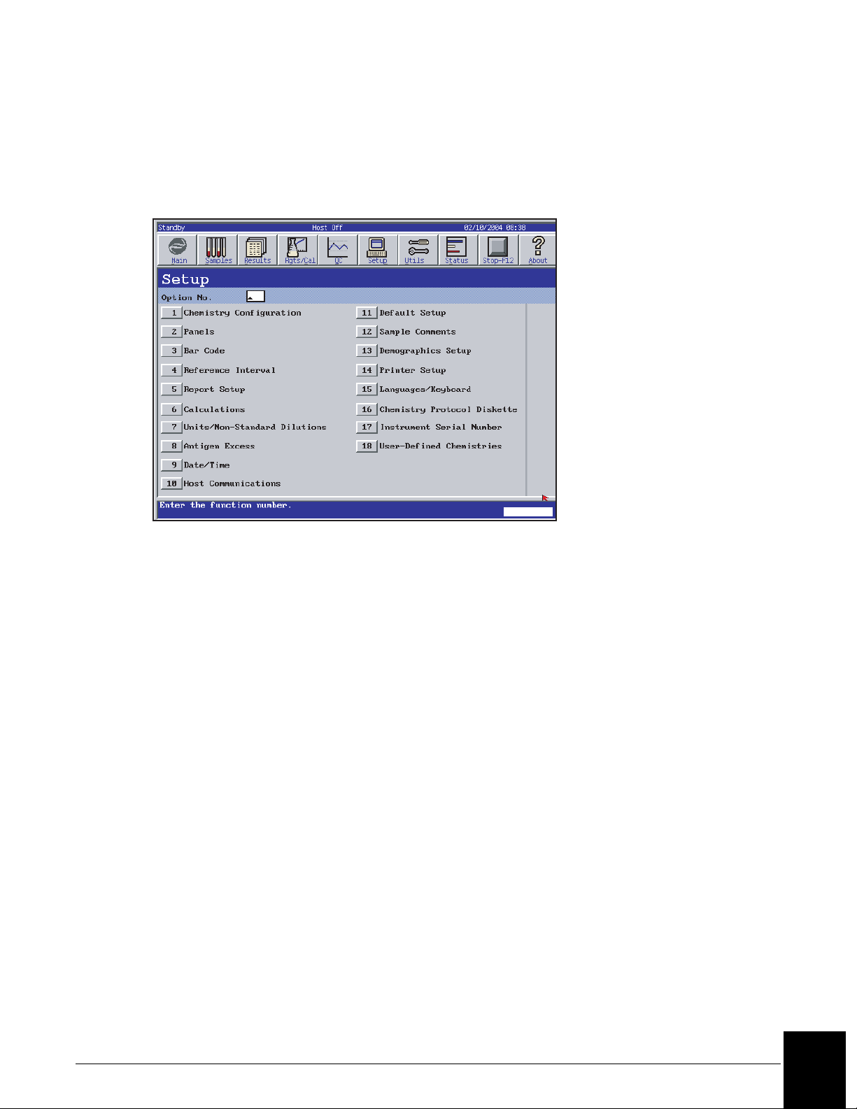
Select Setup from the menu bar. Choose the desired setup option from a numbered button.
(Refer to Figure 5.1.) Refer to the IMMAGE 800 Immunochemistry System Operations
Manual for further details.
E011414S.EPS
Figure 5.1 Setup Screen
Configuring the Chemistry Menu
The chemistry menu available in the sample programming, quality control, panel definition
and other screens is defined by the individual laboratory. The menu contains up to 72
chemistries.
From the Setup screen, select <1> Chemistry Configuration.
Panel Setup
The IMMAGE 800 holds up to 50 chemistry panels in its memory. Each panel is defined with
a name and the chemistries that it contains.
From the Setup screen, select <2> Panels.
IMMAGE 800 Instructions For Use A11409 System Software Configuration
March 2004 Page 5-2
5
Page 22
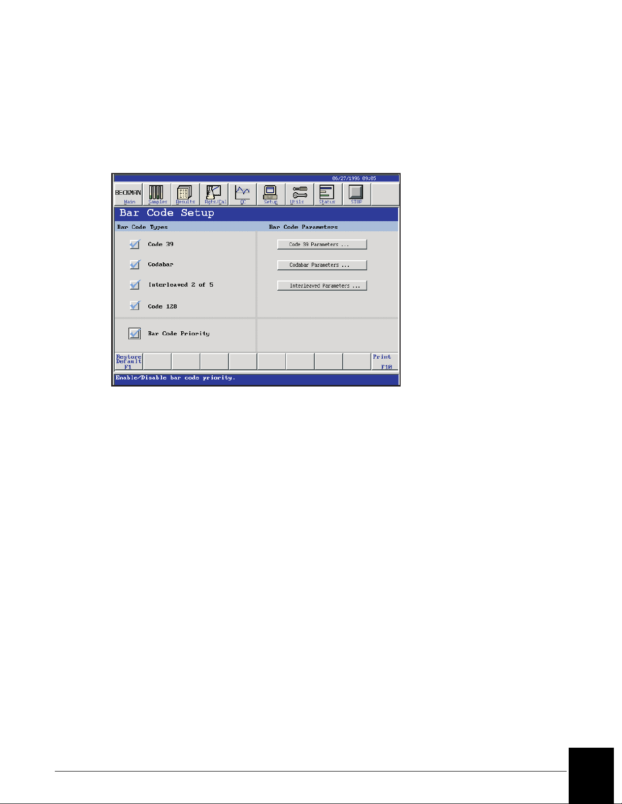
Bar Code Setup
The bar code symbologies recognized by the IMMAGE 800 can be selected. Additionally, the
bar code parameters can be configured to match those of the sample bar codes being read.
From the Setup screen, select <3> Bar Code. (Refer to Figure 5.2.)
E010218S.EPS
Figure 5.2 Bar Code Setup Screen
Bar Code Priority
If the bar code priority is disabled, the batch programming WILL autonumber the racks and
positions.
If the bar code priority is enabled, the batch programming will NOT autonumber the racks and
positions.
• The instrument reads bar coded samples whether or not the Bar Code Priority is enabled.
• Disabling the Bar Code Priority is recommended.
IMMAGE 800 Instructions For Use A11409 System Software Configuration
March 2004 Page 5-3
5
Page 23

Reference Interval Setup
When a reference interval and critical range are defined, they are printed beside the result on
the report. A result outside of the reference interval or critical range is flagged. The interval
and range are defined per chemistry or calculation with distinction made for sample type, sex,
and age group.
Chemistries must be configured and calculations must be enabled before intervals can be
defined.
The minimum entries necessary to save a reference interval are low age, low age unit, high
age, high age unit, low reference interval number and high reference interval number.
From the Setup screen, select <4> Reference Interval.
Selecting the Default
The default interval and range will be printed when an age is not specified in sample
programming or when age is specified but the reference interval has not been defined for that
age.
Only one default can be chosen for a particular interval and range definition grouped by
chemistry/calculation, sample type and sex.
Report Setup
Report formats can be selected for patient reports. A report header, including a facility name
and address, can also be defined. Automatic printing of calibration, control, and patient
reports can also be enabled.
From the Setup screen, select <5> Report Setup.
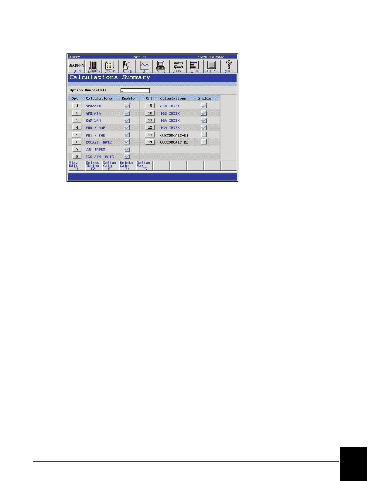
Calculations Setup
There are 12 Beckman Coulter defined calculations that can be enabled for the IMMAGE 800.
The system will automatically calculate and print the final calculation on reports when the
chemistries necessary for the calculation are run.
The system provides a maximum of 28 additional calculations that may be defined, edited,
and/or deleted by the operator. The Custom Calculations feature provides for the reporting of
operator-defined calculations using sample results when chemistries necessary for the
calculations are run. The calculations may involve results from one sample or two linked
samples.
The default for calculations is disabled.
From the Setup screen, select <6> Calculations. (Refer to Figure 5.3.)
IMMAGE 800 Instructions For Use A11409 System Software Configuration
March 2004 Page 5-4
5
Page 24
Units Setup
S
E014091S.EP
Figure 5.3 Calculations Summary Screen
Units can be selected for reporting with the results and displayed throughout the IMMAGE
800 system for each chemistry.
From the Setup screen, select <7> Units.
IMMAGE 800 Instructions For Use A11409 System Software Configuration
March 2004 Page 5-5
5
Page 25

Selecting Non-Standard Dilutions as Default for Each Chemistry
Introduction
The instrument status must be in Standby in order to select a non-standard dilution for a
chemistry. The system allows the user to select a non-standard dilution to use as the initial
dilution every time a particular assay is run.
Selecting a Non-Standard Dilution
Step Action
1 From the Setup screen, select <7> Units/Non-Standard Dilutions.
2 Select the sample type. Then select the options button < > beside the desired
chemistry. Standard and non-standard dilutions are displayed.
3 Select the number beside the desired dilution for the selected chemistry and
sample type. Note that the current default dilution is highlighted. If the chosen
dilution is a non-standard dilution, that dilution will appear on the Units/NonStandard Dilutions screen.
OR
Select <Cancel> to return to the Units/Non-Standard Dilutions screen without
changing the non-standard dilution.
OR
Select <Default> to return to the standard default dilution.
4 Repeat Steps 2-3 for additional chemistries.
When a non-standard dilution has been selected for a chemistry and sample type, whenever
this chemistry is run in this sample type, the system uses the selected non-standard default
dilution as the initial dilution. If the test is out of range at this dilution, the system will step up
or step down to a different dilution.
If the original sample was programmed to run with a standard dilution, and later you changed
the default dilution to a non-standard dilution, the sample will be rerun with the standard
dilution.
IMMAGE 800 Instructions For Use A11409 System Software Configuration
March 2004 Page 5-6
5
Page 26
Configuring Antigen Excess Testing
Antigen excess (AGXS) testing can be enabled or disabled for each appropriate chemistry
configured on the chemistry menu.
The default for AGXS testing is enabled for all the appropriate chemistries.
If AGXS testing is enabled, AGXS testing is always performed for the associated chemistry.
If AGXS testing is disabled, AGXS testing will not be performed for the associated chemistry.
AGXS can be enabled or disabled for an individual sample in Sample Programming.
From the Setup screen, select <8> Antigen Excess.
Date and Time Setup
At installation the system requires the date and time to be set. After this, changing the date or
time is optional. The format of the date and time for the appropriate screens and printouts
may be changed as well.
From the Setup screen, select <9> Date/Time.
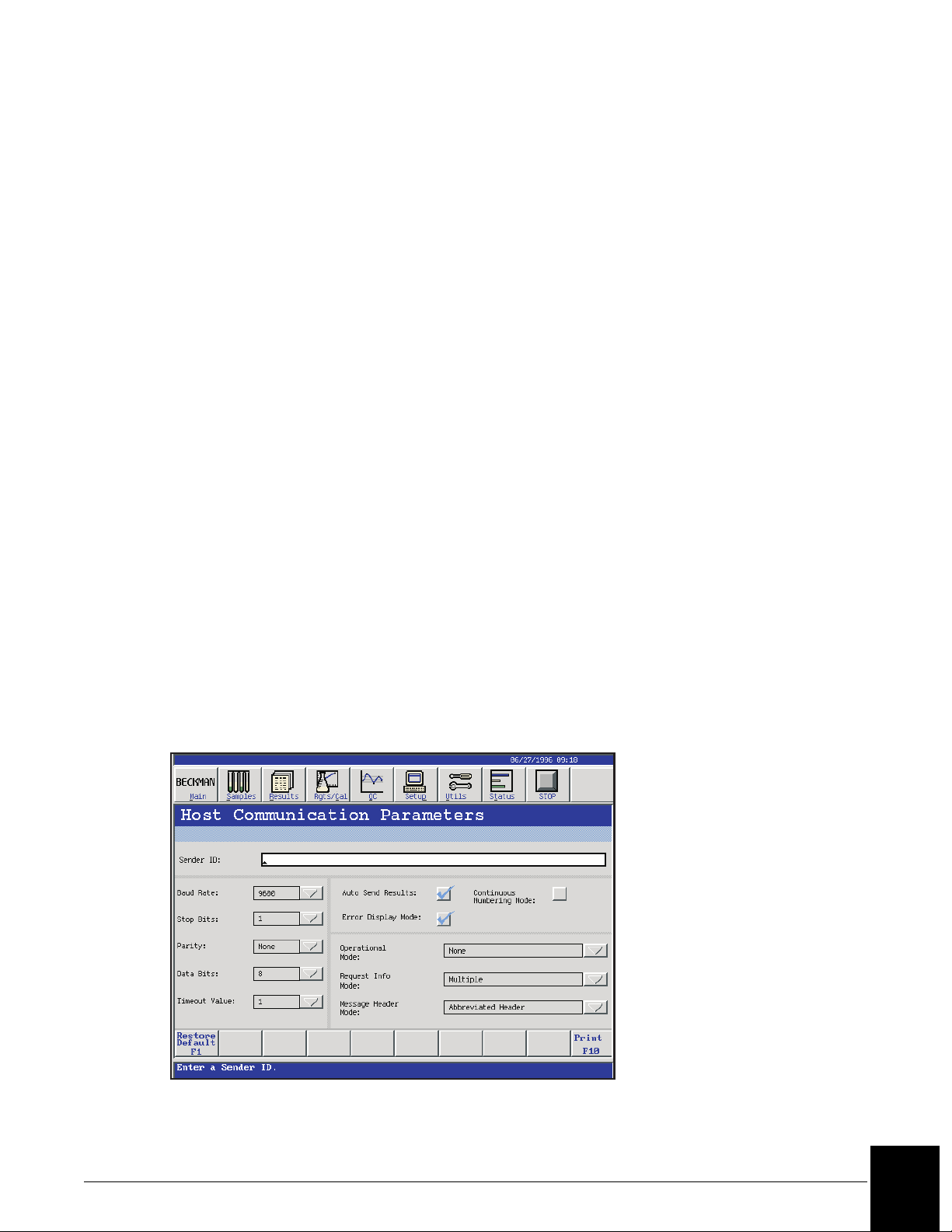
Host Communications Setup
When connecting a laboratory information system (LIS) to the IMMAGE 800, several
parameters must be set. These parameters should be set by the person configuring the
connection between the IMMAGE and the LIS. Further information about all of the host
communications parameters is found in the IMMAGE Immunochemistry Systems Host
Interface Specifications.
From the Setup screen, select <10> Host Communications. (Refer to Figure 5.4.)
E010227S.EPS
Figure 5.4 Host Communications Parameters Screen
IMMAGE 800 Instructions For Use A11409 System Software Configuration
March 2004 Page 5-7
5
Page 27
Default Setup
Default Setup is used to:
• define the default sample type for all samples programmed. The sample type can be
changed for individual samples from the Program Sample screen.
• define the default number of replicates to be run for each sample.
• define the Post Run Summary time (none - 72 hours).
From the Setup screen, select <11> Default Setup.
Sample Comments Setup
Up to 20 sample comments may be predefined on the IMMAGE 800 Immunochemistry
System for use when programming samples on the instrument. These will be presented in a
numbered menu when programming samples.
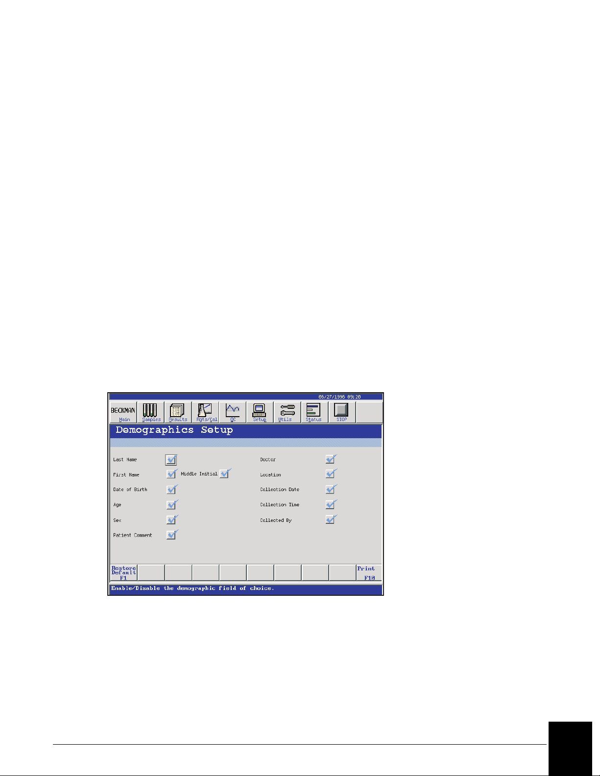
Demographics Setup
The fields which are accessible in the demographics screen of sample programming can be
selected.
To select fields to be displayed in Sample Programming, from the Setup screen, select <13>
Demographics Setup. (Refer to Figure 5.5.)
E010230S.EPS
Figure 5.5 Demographics Setup Screen
Printer Setup
The printer type is a Hewlett Packard Deskjet® or compatible. The paper size can be selected.
From the Setup screen, select <14> Printer Setup.
IMMAGE 800 Instructions For Use A11409 System Software Configuration
March 2004 Page 5-8
5
Page 28

Language Setup
A language can be selected for use for system operations and printouts on the IMMAGE 800.
The keyboard should match the language.
• From the Setup screen, select <15> Languages/Keyboard.
• Select a language from the options button <▼>.
Selecting Japanese from the Language options will cause the Language/
Keyboard selection to become unavailable. Reloading of the software is
necessary to restore the Language/Keyboard Selection option.
• Perform the power off sequence and then the power on sequence. (Refer to IMMAGE 800
Immunochemistry System Instructions for Use CHAPTER 4, System Power On/Off, Power
On Sequence, Power Off Sequence.)
Loading the Chemistry Protocol Diskette
The chemistry protocol diskette is provided with each IMMAGE 800 Immunochemistry
system. It contains essential non-lot specific information about how to run each chemistry.
The chemistry protocol diskette is loaded when the IMMAGE 800 is installed. When new
chemistries become available, a new diskette is provided.
NOTICE
From the Setup screen, select <16> Chemistry Protocol Diskette.
Instrument Serial Number Setup
The serial number of the instrument is entered through the Instrument Serial Number option.
The instrument serial number will be printed on all reports.
From the Setup screen, select <17> Instrument Serial Number.
UDR Chemistry Overview and Precautions
Each laboratory can define its own user-defined reagent (UDR) chemistry protocols using the
templates from the chemistry protocol diskette. After the chemistry protocol diskette is
loaded and the UDR protocol is defined, the UDR chemistry name is available for placement
on the list of configured chemistries for selection in UDR rate mode programming, reference
intervals, UDR calibration, sample programming, control definitions and panels. Refer to the
IMMAGE 800 Immunochemistry System Operations Manual for further details.
IMMAGE 800 Instructions For Use A11409 System Software Configuration
March 2004 Page 5-9
5
Page 29
User-Defined Reagent Chemistry Setup
UDR Chemistry Overview and Precautions
Introduction
Each laboratory can define its own user-defined reagent (UDR) chemistry protocols using the
templates from the chemistry protocol diskette. After the chemistry protocol diskette is
loaded and the UDR protocol is defined, the UDR chemistry name is available for placement
on the list of configured chemistries for selection in UDR rate mode programming, reference
intervals, UDR calibration, sample programming, control definitions and panels.
Precautions
Since Beckman Coulter does not manufacture or otherwise control the sample and
reagents that may be used in user-defined reagent applications, Beckman Coulter
makes no warranty whatsoever with respect to such sample and reagent
performance (including sample carryover, test results, reagent and cartridge
handling), their effect on the system or required system maintenance or the
frequency thereof, or their effect on operator safety. User assumes full responsibility
for use of the proper test protocol and test result generation for the reagent(s)
selected by the user and for any errors or omissions associated therewith. BECKMAN
COULTER EXPRESSLY DISCLAIMS ALL WARRANTIES WITH RESPECT TO THIS
PRODUCT WHETHER EXPRESS OR IMPLIED, INCLUDING WARRANTIES OF
MERCHANTABILITY OR FITNESS FOR A PARTICULAR PURPOSE.
CAUTION
CAUTION
Non-Beckman Coulter reagents, calibrators, and controls can contain components,
not listed on the insert, which may carry over into the system causing chemical or
optical interference. This carryover could adversely affect results on a properly
performing system. Manufacturers of user-defined reagents should be contacted for
disclosure of potentially interfering substances, such as preservatives.
IMMAGE 800 Instructions For Use A11409 System Software Configuration
March 2004 Page 5-10
5
Page 30

Setting Up a UDR Chemistry
Loading the Protocol Diskette
Follow the instructions under Loading the Chemistry Protocol Diskette, earlier in this chapter,
to load the user-defined reagent chemistry protocol templates.
Password Setup Procedure
Once a UDR chemistry has been defined and saved, the user must log in and perform a
password setup procedure. This password protection feature is recommended for security
purposes. The password setup is used to identify specific information, such as:
• who logged in
• which field was updated
• what screen was entered
• what field was changed
This and other information are described in the Display Events log. The password setup is
described in the following steps.
Step Action
1 Select the Password Setup box near upper right corner of the User-Defined
Chemistries screen. Refer to Figure 5.6.
2 The User Log in screen appears. Refer to Figure 5.7. Note that the Username field
defaults to ADMIN. Enter ADMIN in the Password field and select <OK>.
OR
Select <Cancel> to return to the User-Defined Chemistries screen.
3 If <OK> was selected above, the UDR User Setup/Password Protection Mode
screen appears. Refer to Figure 5.8. This screen is used to add or delete a user. Up
to 16 users are allowed. Password protection is enabled by default (i.e., the
Password Protection Mode box is checked.) If the Password Protection Mode box
is disabled (not checked), the password protection feature is not available (i.e., no
prompt after Define and Save.)
To add another user, select a new user name number. Then select <Define Edit
User> and proceed to Step 4.
4 A Define/Edit User screen appears. Refer to Figure 5.9. Enter a new user name in
the Username field. Enter your password in the Password field. Enter the same
password in the Confirm Password field.
5 To delete a user, select the username number and select <Delete User>.
OR
Select <Cancel> to return to the Password Protection Mode Screen.
6 Select <Exit> to return to the User Defined Chemistries screen.
IMMAGE 800 Instructions For Use A11409 System Software Configuration
March 2004 Page 5-11
5
Page 31

Figure 5.6 User-Defined Chemistries Screen
E011417S.EPS
E011434S.EPS
Figure 5.7 User Login Screen
IMMAGE 800 Instructions For Use A11409 System Software Configuration
March 2004 Page 5-12
5
Page 32

E011435S.EPS
Figure 5.8 UDR User Setup/Password Protection Mode Screen
E011436S.EPS
Figure 5.9 Define/Edit User Screen
IMMAGE 800 Instructions For Use A11409 System Software Configuration
March 2004 Page 5-13
5
Page 33

Accessing Define/Edit
The instrument status must be in Standby in order to proceed with the steps below to access
the Define/Edit screen.
Step Action
1 From the Setup screen, select <18> User-Defined Chemistries.
2 Select the UDR Option Number. (Refer to Figure 5.6.)
3Select Define/Edit [F1]. (Refer to Figure 5.10 and Figure 5.11.) Continue to
"Beginning a New UDR Protocol Definition" in this chapter.
E011418S.EPS
Figure 5.10 Define/Edit User-Defined Chemistry Screen, Page 1
IMMAGE 800 Instructions For Use A11409 System Software Configuration
March 2004 Page 5-14
5
Page 34

E011428S.EPS
Figure 5.11 Define/Edit User-Defined Chemistry Screen, Page 2
IMMAGE 800 Instructions For Use A11409 System Software Configuration
March 2004 Page 5-15
5
Page 35

Defining a UDR Chemistry
Description of Definition Fields
The following table describes the fields of the Define/Edit User-Defined Chemistry screen,
Page 1. (Refer to Figure 5.10.) Use the tab key to navigate.
Table 5.1 Protocol Definition Fields, Page 1
Field Entries Allowed Function
Chem Name Two to five alphanumeric
characters
Reagent Lot Number A maximum of eight
alphanumeric characters
Cartridge Lot Number A maximum of eight
alphanumeric characters
Cartridge Serial Number A maximum of four
alphanumeric characters
AGXS Limit 1-9999 Identifies Antigen Excess limit
Comments A maximum of 20
alphanumeric characters
Units Selection from list Concentration Units of UDR
Conversion Factor Not applicable • Displays the conversion
Unique name for chemistry.
Identifies reagent lot number.
Identifies cartridge lot number.
Identifies unique serial number
of UDR cartridge.
rate.
Provides additional vendor
information, or other
comments.
results.
factor input from the Units
option button.
Protocol Selection from list:
• Non-Competitive
nephelometric
• Competitive nephelometric
• Non-Competitive NIPIA
• Competitive NIPIA
Reagent Expiration Date Date in order as defined in
Date Setup
IMMAGE 800 Instructions For Use A11409 System Software Configuration
March 2004 Page 5-16
• Immunoprecipitin reaction
detected by rate
nephelometry.
• Inhibition immunoprecipitin
reaction detected by rate
nephelometry.
• Immunoprecipitin reaction
detected by rate turbidimetry.
• Inhibition immunoprecipitin
reaction detected by rate
turbidimetry.
Reagent will be flagged on
reports as expired after this
date.
(1 of 2)
5
Page 36

Table 5.1 Protocol Definition Fields, Page 1, continued
Field Entries Allowed Function
Tests per Cartridge 1-300 Identifies the number of tests
available in the reagent
cartridge.
AGXS Enabled Select (check) to enable Allows usage of AGXS Limit
field.
(2 of 2)
The following table describes the protocol fields of the Define/Edit User-Defined Chemistry
screen, Page 2. (Refer to Figure 5.11.)
Table 5.2 Protocol Definition Fields, Page 2
Field Entries Allowed Function
Buffer BUF 1 to 4, or
BUF 10 to 15
Diluent DIL 1 to 4, or
DIL 10 to 15
Sample or Dilution
Volume
Reaction Buffer Volume "0"; or from
Compartment A Volume
(Refer to Figure 5.12.)
Compartment B Volume
(Refer to Figure 5.12.)
Gain 1, 2, 3, 4 Signal amplification. As gain
Cal Dilution 1:1; or 1:5 to 1:50 Determines dilution ratio for
3 µL to 21 µL or
3 µL to 75 µL, depending
on the sample dilution
195 µL to 300 µL
5 µL to 235 µL Reagent volume aspirated from
"0" ; or from
5 µL to 235 µL
Identifies type of buffer used in
test.
Identifies type of diluent used in
test.
Sample or dilution volume
dispensed to reaction cuvette.
Reaction buffer volume dispensed.
cartridge, compartment A.
Reagent volume aspirated from
cartridge, compartment B.
number increases, signal
amplification increases.
calibration.
Sample Dilution 1:1; or 1:5 to 1:50 Determines dilution ratio for
sample predilution.
Reaction Time Select from list: 1.5 to 10
minutes
IMMAGE 800 Instructions For Use A11409 System Software Configuration
March 2004 Page 5-17
Interval in which reaction readings
are taken after addition of the last
reagent to the reaction mixture.
5
Page 37

A
6
1
77
B
2
3
1. Reagent Compartment Cover
2. Reagent Carousel
3. Reaction Buffer Bottle
4. Reagent Cartridges (Compartments A and B)
4
5. Reagent Bar Code Reader
6. Fans
7. Temperature Sensor
5
A011410P.EPS
Figure 5.12 The Reagent Compartment
The following table describes the calibration fields of the Define/Edit User-Defined
Chemistry screen, Page 3. (Refer to Figure 5.13.)
Table 5.3 Calibration Definition Fields, Page 3
Field Entries Allowed Function
Levels 4 to 9 Identifies the number of calibrators
used in test.
Replicates 1 to 9 Allows a number of tests to be
repeated for each calibration level.
Update Level 1 to 9 Single-point calibration setpoint
update level.
Replicates 1 to 9 Set point update replicate.
Cal Level Setpoints Up to 6 digits with a decimal
point, or seven digits.
Identifies concentration value for
each calibration level in ascending
order where Level 1 is the lowest
concentration value.
IMMAGE 800 Instructions For Use A11409 System Software Configuration
March 2004 Page 5-18
5
Page 38

Figure 5.13 Define/Edit User-Defined Chemistry Screen, Page 3
Order of Reaction
The following table describes the order of reaction as determined by the type and volume of
reaction components defined.
Table 5.4 Order of Reaction
E011419S.EPS
If the Reaction
Buffer Volume is…
and the
Compartment B
the Order of Reaction is…
Volume is…
Between 195-300 µL 0 µL UDR buffer > Incubate > Neat or
Diluted Sample > Compartment A
Reagent starts reaction
Between 195-300 µL Between 5-235 µL UDR buffer > Compartment B
Reagent > Incubate > Neat or Diluted
Sample > Compartment A Reagent
starts reaction
0 µL Between 195-235 µL Compartment B Reagent > Neat or
Diluted Sample > Incubate >
Compartment A Reagent starts
reaction
IMMAGE 800 Instructions For Use A11409 System Software Configuration
March 2004 Page 5-19
5
Page 39

Recommended Order for UDR AGXS Flagging Limit Use
Step Action
1 Define UDR parameters
2 Perform UDR multi-point calibration.
3 Approve UDR multi-point calibration.
Note: If calibration verification is desired, run the calibration verification
BEFORE changing the sample dilution.
4 Change UDR sample dilution (optional).
5 Perform UDR AGXS Limit determination testing using UDR Rate Mode.
6 Enter UDR AGXS Limit (rate value) and select (check) the AGXS Enable box to
begin UDR AGXS flagging. The AGXS Enable box is located in the Define/Edit
User-Defined Chemistry screen (Refer to Figure 5.10).
7 Run UDR samples and perform single-point UDR calibration updates.
Additional Information
Refer to IMMAGE 800 Immunochemistry System Operation Manual CHAPTER 3, Theory of
Operations, Principles of Methodologies for theory of operation information.
Beginning a New UDR Protocol Definition
The instrument status must be in Standby to proceed with the steps below. Refer to the
Define/Edit User-Defined Chemistry screen shown in Figure 5.10.
Step Action
1 From Page 1 of the Define/Edit User-Defined Chemistry screen, enter the UDR
chemistry name in the Chem Name field. This field is limited to 2-5 alphanumeric
characters. The chemistry name must not be in use for any other chemistry or
calculation.
2 Select the options button <▼> beside the Units field.
3 Select the number for the desired unit.
4 Enter the reagent lot number in the Reagent Lot Number field.
5 Select the options button <▼> beside the Protocol field.
6 Select the number for the desired protocol.
7 Select the Cartridge Lot Number field.
8 Enter the cartridge lot number from the UDR cartridge. The lot number is found
on the bar code label of the UDR cartridge supplied by Beckman Coulter.
(1 of 2)
IMMAGE 800 Instructions For Use A11409 System Software Configuration
March 2004 Page 5-20
5
Page 40

Step Action, continued
9 Select the options button <▼> beside the Reagent Expiration Date field.
10 Enter the reagent expiration date.
NOTICE
The expiration date must not be the current date. Recalibration will be necessary
when the expiration date is changed.
11 Select <OK> to enter the expiration date into system.
OR
Select <Cancel> to exit the dialog box without entering the date. Continue to
“Defining UDR Sample/Reagent Volumes.”
12 Enter the reagent cartridge serial number in the Cartridge Serial Number field.
The serial number is found on the bar code label of the UDR cartridge supplied by
Beckman Coulter.
13 Enter the number of tests in the Tests per Cartridge field. The maximum number
of tests is 300.
14 If desired, select the Comments field and enter vendor information or other
comments. This field is limited to 20 alphanumeric characters.
(2 of 2)
Defining an AGXS Limit
The AGXS Limit is a user-defined value. The AGXS Limit feature will only be available if the
UDR has a status of "calibrated" and uses a "Non-Competitive Nephelometric" or "NonCompetitive NIPIA" protocol. Entry of this value in the AGXS Limit field is only available
after a UDR multi-point calibration has been performed and approved.
Entering an AGXS Limit value into the UDR definition will clear the calibration program of
the defined UDR. The AGXS limit is calibration specific; therefore, recalibrating a UDR
using a multi-point calibration will clear the AGXS Limit field and disable AGXS flagging.
During the sample run, if the calibrated rate for a UDR sample reaction is equal to or greater
than the value entered for the AGXS Limit in the UDR definition, the system will suppress the
results and display ******* in the results column on the results display and printout instead of
a numerical result. AGXS flagging shall not apply during UDR Rate Mode runs.
IMMAGE 800 Instructions For Use A11409 System Software Configuration
March 2004 Page 5-21
5
Page 41

Refer to follow the steps to enter an AGXS flagging rate value.
Step Action
1 From the User-Defined Chemistries screen, select the chemistry for AGXS
flagging. (Refer to Figure 5.6.)
2Select Define Edit.
3 A user defined warning message appears. Read the message and select <OK>.
4 Select the AGXS Enable box.
5 Enter Rate Units into AGXS Limit field.
6Select Save [F9].
7 If your password is protected, then refer to the Password Setup Procedure in this
chapter and enter your user name and password.
8Select <OK>.
Defining UDR Sample/Reagent Volumes
The minimum total cuvette volume of reagent(s) and sample is 195 µL.
The maximum total cuvette volume of reagent(s) and sample is 365 µL.
The instrument status must be in Standby in order to proceed with the steps below to define
UDR sample and reagent volumes. (Refer to Figure 5.11.)
Step Action
1 From Page 2 of the Define/Edit User-Defined Chemistry screen, select the Buffer
options button beside the Buffer field.
2 Select the buffer type from the list.
3 Select the Diluent options <▼> button beside the Diluent field.
4 Select the diluent type from the list.
(1 of 3)
IMMAGE 800 Instructions For Use A11409 System Software Configuration
March 2004 Page 5-22
5
Page 42

Step Action, continued
5 Enter the volume of sample or sample dilution to be aspirated and dispensed in the
Sample or Dilution Volume field.
If the Sample Dilution field
entry is...
the Sample or Dilution Volume field
may be...
1:5 to 1:50 3 µL to 75 µL
1:1 (undiluted) 3 µL to 21 µL
NOTICE
Aspiration of neat serum and/or plasma sample volumes greater than 15 µL may
result in carryover and is not recommended.
6 Enter the reaction buffer volume to be aspirated and dispensed in the Reaction
Buffer Volume field. Entries may be "0" or from 195 µL to 300 µL.
7 Enter the volume of reagent to be aspirated and dispensed from Compartment A in
the Compartment A Volume field. Entries may be from 5 µL to 235 µL.
8 Enter the volume of reagent to be aspirated and dispensed from Compartment B in
the Compartment B Volume field.
If the Reaction Buffer
Volume field entry is...
the Compartment B Volume
field entry may be...
0 195 µL to 235 µL
195 µL to 300 µL 0 or 5 µL to 235 µL
9 Enter the gain in the Gain field. Entries may be 1, 2, 3, or 4. The gain increases
as the number increases.
10 Enter the calibration dilution in the Cal Dilution field. Entries may be from 1:5 to
1:50.
OR
Enter 1:1 for an undiluted sample.
The Sample Dilution field automatically displays the same value as the Cal
Dilution field. No input is allowed until after calibration and approval.
(2 of 3)
IMMAGE 800 Instructions For Use A11409 System Software Configuration
March 2004 Page 5-23
5
Page 43

Step Action, continued
11 After calibration and approval, if the desired sample dilution is different from the
calibration dilution, enter the sample dilution in the Sample Dilution field.
Entries may be from 1:5 to 1:50.
OR
Enter 1:1 for an undiluted sample.
12 Select the options button <▼> beside the Reaction Time field.
13 Select the reaction time number from the list.
14 Select the <Page Down> button to go to Page 2 of the Define/Edit User-Defined
Chemistry screen.
15 Continue to "Defining UDR Calibration Information."
(3 of 3)
IMMAGE 800 Instructions For Use A11409 System Software Configuration
March 2004 Page 5-24
5
Page 44

Defining UDR Calibration Information
Defining UDR Calibration Information
The out-of-range low value for the protocol is the lowest non-zero calibrator setpoint
concentration. The out-of-range high value for the protocol is the highest calibrator setpoint
concentration.
The instrument status must be in Standby in order to proceed with the steps below to define
the calibration information on Page 3 of the Define/Edit User-Defined Chemistry screen.
Refer to Figure 5.13
Step Action
1 From Page 3 of the Define/Edit User-Defined Chemistry screen, enter the
number of Cal Setpoint levels in the Levels field. Entries may be from
four to nine.
2 Enter the number of replicates to be run per Cal Setpoint level in the
Replicates field. Entries may be from one to nine.
3 Enter a Cal Level number in the Update Level field for a single-point
calibration update. Entries may be from one to nine.
4 Enter the number of replicates to be run for the Update Level in the
Replicates field. Entries may be from one to nine.
5 Enter the concentration value in each of the Cal Setpoint fields. The
concentration values must be in ascending order with Level 1 being the
lowest concentration. Each field entry is limited to seven digits or six
digits with a decimal point.
NOTICE
The number of calibration levels limits the type of curve-fit model
applicable to the UDR. (Refer to Approving a Calibration, "Curve-Fit
Model Descriptions", later in this chapter.)
6Select Save [F9] to save the protocol and calibration information.
OR
Select Cancel [F10] to exit the screen without saving the protocol.
7 Go to the User-Defined Chemistries screen (Figure 5.6) and select Chem
Config [F9] to configure the UDR chemistry. (Refer to Configuring the
Chemistry Menu in this chapter.)
8 From the Chemistry Configuration screen, select UDR Main [F9] to return
to the User-Defined Chemistries screens.
IMMAGE 800 Instructions For Use A11409 System Software Configuration
March 2004 Page 5-25
5
Page 45

Deleting UDR Chemistries
Removing a UDR Chemistry from the Chemistry Menu
This function removes the UDR chemistry from the chemistry configuration menu, from any
configured control, and from any configured panel.
Deleting a UDR Definition
The Delete function deletes a UDR definition only if the chemistry has been removed from the
chemistry menu. When the UDR definition is deleted, the UDR reference intervals and all
associated, non-archived patient results are deleted. Refer to IMMAGE 800
Immunochemistry System Operation Manual CHAPTER 10, Utilities, Backup/Restore.
The instrument status must be in Standby in order to proceed with the steps below to delete a
UDR definition.
Step Action
1 From the Setup screen, select <18> User-Defined Chemistries.
2 Choose a number beside the chemistry to be deleted.
3Select Delete [F2]. (Refer to Figure 5.14.)
4Select <OK> to delete the chemistry.
OR
Select <Cancel> to return to the User-Defined Chemistries screen without
deleting the chemistry.
5 Remove the reagent cartridge from the reagent carousel.
E014047S.EPS
Figure 5.14 Delete User-Defined Chemistry Dialog Box
IMMAGE 800 Instructions For Use A11409 System Software Configuration
March 2004 Page 5-26
5
Page 46

Editing UDR Definitions
Introduction
A previously defined UDR definition may be recalled and edited. Editing the sample dilution
and/or AGXS Limit of a defined UDR clears the calibration programs for the UDR. Editing
Comments, the Cartridge Serial Number and/or refilling a cartridge will not affect calibration.
Editing anything else clears the calibration programs, cancels the calibration, clears the AGXS
Limit, and disables AGXS flagging. The edited UDR definition is saved with the same
chemistry name. Refer to Table 5.5 for further information.
Table 5.5 UDR Editing Function
Editing Function Calibration
Clears calibration programs Cleared Calibrated Cannot Change
Clears calibration programs and
Cancels the calibration
Editing a UDR Definition
The units and chemistry name of the UDR cannot be changed unless the UDR is first removed
from the chemistry menu.
The instrument status must be in Standby in order to proceed with the steps below to edit a
UDR definition.
Step Action
1 From the Setup screen, select <18> User-Defined Chemistries.
2 Select a number beside a defined UDR position. (Refer to Figure 5.6.)
3Select Define/Edit [F1].
4 Refer to Defining a UDR Chemistry to edit the UDR definition and calibration
information.
Rack
Calibration
Status
Curve-Fit
Model
Cleared Uncalibrated Cannot Change
NOTICE
Editing the sample dilution or AGXS Limit of a defined UDR clears the calibration
programs for that UDR. Editing Comments, Cartridge Serial and/or Refill numbers
does not affect calibration. Editing anything else clears the calibration programs,
cancels the calibration, clears the AGXS Limit and disables AGXS flagging.
If the serial number is changed in the protocol definition, the cartridge identified
by the overwritten serial number is no longer usable, regardless of the number of
tests remaining.
IMMAGE 800 Instructions For Use A11409 System Software Configuration
March 2004 Page 5-27
5
Page 47

Editing a UDR Definition is summarized in Table 5.6 below.
Table 5.6 Editing a UDR Definition
Edited UDR Definition Effect on Calibration Effect on AGXS Flagging
Comments
Serial Number
Refill Cartridge
Sample Dilution
AGXS Limit
All Other Parameters Clears Program
No Effect
Status: Calibrated
Clears Program
Status: Calibrated
Cancels Calibration
Status: Uncalibrated
No Effect
No Effect
Clears AGXS Limit
Disable Flagging
IMMAGE 800 Instructions For Use A11409 System Software Configuration
March 2004 Page 5-28
5
Page 48

Loading UDR Reagent Cartridges
Introduction
The UDR reagent cartridges must be loaded before performing a run.
Description of Cartridge
The UDR cartridge provided by Beckman Coulter contains the following information:
• Cartridge lot number
• Cartridge serial number.
Limits
• Six UDR cartridges may be loaded on the reagent carousel at one time.
• Each UDR cartridge has a set number of 300 tests. When the 300 tests count down to zero,
a new UDR serial number and/or cartridge lot number must be defined and loaded.
• When the cartridge is level sensed as empty, but more tests are available on the Reagent/
Calibration Status screen, the UDR cartridge may be refilled and reused until the tests
remaining is zero.
Loading UDR Cartridges
Follow the instructions in IMMAGE 800 Immunochemistry System Operation Manual
CHAPTER 6, Reagents/Calibration, Loading/Unloading Reagent Cartridges, "Loading
Reagent Cartridges."
Refilling UDR Cartridges
A UDR can be programmed to run a maximum of 300 tests. If the cartridge holds less than
300 tests, the cartridge may be refilled to reach the maximum 300 tests. Follow the steps
below to refill the UDR cartridge.
Step Action
1 Go to the User-Defined Chemistry screen. (Refer to Figure 5.6.)
2 Select a UDR.
3Select Define/Edit [F1].
4Select <OK> to close the warning message.
5Select Refill [F8] at the Defined/Edit-User Defined Chemistry screen. (Refer to
Figure 5.10.)
6 Select the Cartridge Serial Number on the UDR Cartridge Refill screen. (Refer
to Figure 5.15.)
(1 of 2)
IMMAGE 800 Instructions For Use A11409 System Software Configuration
March 2004 Page 5-29
5
Page 49

Step Action, continued
7Select <Refill>. The system will update tests remaining in the cartridge to the
number of tests defined in the Defined/Edit-User Defined Chemistry screen.
OR
Select <Exit> to return to the Defined/Edit-User Defined Chemistry screen
without refilling the cartridge.
8 Refill the cartridge.
(2 of 2)
E011420S.EPS
Figure 5.15 UDR Cartridge Refill Screen
The UDR Cartridge Refill screen (Figure 5.15) is defined in Table 5.7:
Table 5.7 UDR Cartridge Refill Screen
Screen Item Screen Definition
Chem Name Chemistry Name as defined in Figure 5.10.
Reagent Lot Number Reagent Lot Number as defined in Figure 5.10.
Tests per cartridge Tests per cartridge as defined in Figure 5.10.
Serial Number Cartridge Serial number as defined in Figure 5.10
Tests left Number of tests remaining from tests per cartridge defined in
Figure 5.10.
Total tests left Number of tests remaining from 300 total tests per cartridge.
IMMAGE 800 Instructions For Use A11409 System Software Configuration
March 2004 Page 5-30
5
Page 50

Removing UDR Cartridges
Follow the instructions in IMMAGE 800 Immunochemistry Operations Manual, CHAPTER
6, Reagents/Calibration, Loading/Unloading Reagent Cartridges, "Removing Cartridges from
The Reagent Carousel."
IMMAGE 800 Instructions For Use A11409 System Software Configuration
March 2004 Page 5-31
5
Page 51

Loading/Clearing UDR Buffer and Diluent
Introduction
Beckman Coulter IMMAGE 800 buffers and diluents, or user-prepared solutions, may be used
as UDR buffer and diluent. However, the UDR buffer and diluent are given a specific name on
the sample or reagent carousel. The positions and lot numbers of UDR buffer and diluent
must be entered into the computer.
• Up to 4 bottles of UDR buffers may be placed on the inner section of the reagent carousel.
• Up to 4 bottles of UDR sample diluents may be placed on the inner section of the sample
carousel.
Checking UDR Buffer/Diluent Status
The instrument status must be in Standby in order to proceed with the steps below to check the
buffer and diluent status before a run.
Step Action
1Select Reagents/Cal from the menu bar.
2Select Buffer/Diluent [F3]. (Refer to Figure 5.16.)
3 Check the % Remaining for a sufficient amount to complete a run.
• The designation for a UDR buffer is BUF1-4 and BUF 10-15. BUF 1-4 is
designated for system buffer. BUF 10-15 is designated for user-defined buffer.
• The designation for a UDR diluent is DIL1-4 and DIL 10-15. DIL 1-4 is
designated for system diluent. DIL 10-15 is designated for user-defined diluent.
E014048S.EPS
Figure 5.16 Buffer/Diluent Status Dialog Box
IMMAGE 800 Instructions For Use A11409 System Software Configuration
March 2004 Page 5-32
5
Page 52

Loading a New Lot of UDR Buffer/Diluent or Changing a Position
Follow the instructions in IMMAGE 800 Immunochemistry Operations Manual, CHAPTER
6, Reagents/Calibration, Loading/Clearing Buffers and Diluents, "Loading A New Lot Or
Changing A Position."
Replacing the Same Lot of UDR Buffer/Diluent
Follow the instructions in IMMAGE 800 Immunochemistry Operations Manual, CHAPTER
6, Reagents/Calibration, Loading/Clearing Buffers and Diluents, "Replacing the Same Lot."
After Loading Buffers and Diluents
NOTICE
Recalibration of affected reagents may be necessary when buffer or diluent lot numbers
are changed.
The system assumes that lot numbers and position numbers for buffers or diluents remain the
same from run to run until changed by the user.
The % Remaining volume on the Buffer/Diluent Status dialog box is updated during a
sample run.
Clearing a UDR Buffer/Diluent Position
Refer to IMMAGE 800 Immunochemistry Operations Manual, CHAPTER 6, Reagents/
Calibration, Loading/Clearing Buffers and Diluents, "Clearing a Buffer or Diluent Position."
IMMAGE 800 Instructions For Use A11409 System Software Configuration
March 2004 Page 5-33
5
Page 53

Programming Rate Mode
Introduction
After the UDR chemistry protocol is defined and the chemistry is configured, Rate Mode is
used to optimize UDR parameters. After running the UDR chemistry, a report with only
instrument responses (IR) is automatically generated. A maximum of six UDRs may be
programmed at one time in rate mode. Rate Mode can be run on a calibrated or uncalibrated
UDR.
Programming Rate Mode
The instrument status must be in Standby in order to proceed with the steps below to program
a UDR for rate mode.
Step Action
1 From the User-Defined Chemistry screen, select Rate Mode [F3]. (Refer to
Figure 5.17.)
2 Select up to six of the UDR chemistries.
3Select <OK> to continue. Rate Mode may be run on a calibrated or uncalibrated
UDR.
NOTICE
Rate results are always uncalibrated rate, whether the UDR is calibrated or
uncalibrated.
OR
Select <Cancel> to exit rate mode and return to the User-Defined Chemistry
screen.
4 From the UDR Rate Mode Assign screen (Refer to Figure 5.18.), enter an
available rack number in the Rack field.
OR
Select Clear Racks [F1] and Enter the racks and/or positions to clear.
Select <OK> to clear or <Cancel> to exit without clearing.
5 Enter a position number in the Pos field. Up to nine positions may be entered.
6 Enter a Sample ID in the Sample ID field for each position assigned. Up to 15
characters may be entered.
7Select Save [F9] to save the program.
OR
Select Cancel [F10] to exit the screen without saving the program.
8 Repeat Steps 1-7 to program additional racks for rate mode.
9 Print a Load List from Sample Programming.
(1 of 2)
IMMAGE 800 Instructions For Use A11409 System Software Configuration
March 2004 Page 5-34
5
Page 54

Step Action, continued
10 Load the samples on the sample carousel.
11 Select Main from the menu bar and Run.
12 Select <OK> in the Check Dilution Segments dialog box to start the run.
OR
Select <Cancel> to exit without starting the run.
E014049S.EPS
(2 of 2)
Figure 5.17 UDR Rate Mode Dialog Box
Figure 5.18 UDR Rate Mode Assign Screen
E014050S.EPS
IMMAGE 800 Instructions For Use A11409 System Software Configuration
March 2004 Page 5-35
5
Page 55

Additional Information
Refer to IMMAGE 800 Immunochemistry Operations Manual, CHAPTER 7, Preparing for
Programming/Running, Clearing a Sample and Requesting a Load List.
Refer to IMMAGE 800 Immunochemistry Operations Manual, CHAPTER 8, Results Recall,
Printing Recalled Results to reprint UDR rate mode results.
Refer to IMMAGE 800 Immunochemistry Operations Manual, APPENDIX C, Reports for an
example of a Rate Mode report.
IMMAGE 800 Instructions For Use A11409 System Software Configuration
March 2004 Page 5-36
5
Page 56

Calibrating a UDR Chemistry
Introduction
A UDR can be calibrated by using a multi-point calibration. Subsequently, this calibration
may be updated using a single-point update calibration. The UDR chemistry calibration, using
a multi-point calibration or single-point update, requires that the protocol definition be
completed and the chemistry name configured. The calibration is programmed from the UserDefined Chemistries screen shown in Figure 5.6. The calibrators are run as routine test
samples using the defined protocol. A UDR calibration must be on a separate run from
samples for that UDR chemistry. The instrument response (IR) for each calibrator replicate is
generated.
Once the calibration is approved, the UDR cal status is in Calibrated and UDR chemistries
can be run with other Beckman Coulter chemistries. Using the UDR calibration data, the
system will calculate a final result in the concentration units selected in the protocol.
Programming a UDR Calibration
The instrument status must be in Standby in order to proceed with the steps below to program
a UDR calibration.
Step Action
1 From the User-Defined Chemistries screen, select Request Cal [F4]. The UDR
chemistries on the reagent carousel will be displayed. (Refer to Figure 5.19.)
2 Select up to six UDR chemistries for calibration.
3Select <OK> to continue.
OR
Select <Cancel> to return to the User-Defined Chemistries screen.
4 From the UDR Cal Assign screen, enter an available rack number in the Rack
field. (Refer to Figure 5.20.)
OR
Select Clear Racks [F1] and enter the racks and/or positions to clear.
Select <OK> to clear or <Cancel> to exit without clearing.
5 After a rack number is entered, the position numbers will automatically fill in the
Pos field according to the levels defined for the chemistry displayed. The
calibrators must be programmed in ascending concentration, with Level 1 being
the lowest concentration.
6 Enter a Cal ID in the Cal ID field (optional). Up to 18 characters may be entered.
(1 of 2)
IMMAGE 800 Instructions For Use A11409 System Software Configuration
March 2004 Page 5-37
5
Page 57

Step Action, continued
7Select Save [F9] or a menu bar icon to save the calibration program for the
displayed chemistry.
OR
Select Cancel [F10] to exit the screen without saving any calibration programs.
8 Repeat Steps 4-7 to program additional racks for calibration of other UDR
chemistries.
E014051S.EPS
(2 of 2)
Figure 5.19 UDR Request Cal Dialog Box
Figure 5.20 UDR Multi-point Cal Assign Screen
E014052S.EPS
IMMAGE 800 Instructions For Use A11409 System Software Configuration
March 2004 Page 5-38
5
Page 58

Programming a Single-Point UDR Calibration
A single-point calibration update can be performed on a UDR after a multi-point calibration
has been performed and approved. This option is not available prior to multi-point calibration.
The single-point calibration update result is compared to the multi-point calibration and the
system calculates a scale factor. After the update is approved, the scale factor is applied to
quality control results and patient results.
The instrument status must be in Standby in order to program a single-point UDR calibration.
Program a single-point calibration as follows:
Step Action
1 From the User-Defined Chemistries screen, select Request Cal [F4]. (Refer to
Figure 5.6.) The UDR chemistries on the reagent carousel will be displayed.
2 Select up to six UDR chemistries for calibration.
3Select <OK> to continue.
Select <Cancel> to return to the User-Defined Chemistries screen.
4 From the UDR Cal Assign screen, select (check) the single-point update box. The
predefined update single-point level and the Cal ID fields will be enabled. (Refer
to Figure 5.21.)
OR
5 From the UDR Cal Assign screen, enter an available rack number in the Rack
field.
OR
Select Clear Racks [F1] and enter the racks and/or positions to clear.
Select <OK> to clear or <Cancel> to exit without clearing.
6 After a rack number is entered, fill in the Pos field according to the level defined
for the chemistry displayed.
7 Enter a Cal ID in the Cal ID field (optional). Up to 18 characters may be entered.
8Select Save [F9] or a menu bar icon to save the calibration program for the
displayed chemistry.
OR
Select Cancel [F10] to exit the screen without saving any calibration programs.
9 Repeat Steps 1-7 to program additional racks for calibration of other UDR
chemistries.
IMMAGE 800 Instructions For Use A11409 System Software Configuration
March 2004 Page 5-39
5
Page 59

Figure 5.21 UDR Cal Assign Screen
Requesting a UDR Cal Load List
The instrument status must be in Standby in order to proceed with the steps below to request a
UDR load list.
Step Action
1 From either the User-Defined Chemistries screen or the UDR Cal Assign screen,
select UDRCal LdList [F6]. (Refer to Figure 5.22.)
2Select Print [F10] to print the load list or UDRCal [F9] to return to the UDR Cal
screen. (Refer to IMMAGE 800 Immunochemistry System Operations Manual,
APPENDIX C, Reports for an example of a Calibration Load List.)
E011421S.EPS
IMMAGE 800 Instructions For Use A11409 System Software Configuration
March 2004 Page 5-40
5
Page 60

Figure 5.22 User-Defined Calibration Load List Screen
Running the UDR Calibration
The instrument status must be in Standby in order to proceed with the steps below to run a
UDR calibration.
Step Action
1 Load the calibration samples in the appropriate racks.
2Select Main from the menu bar and Run.
3Select <OK> in the Check Dilution Segments dialog box to start the run.
Select <Cancel> to exit without starting the run.
4 When the calibration run is finished, a multi-point or single-point UDR
Calibration Results report is printed. Continue to "Approving a UDR
Calibration."
E011422S.EPS
OR
IMMAGE 800 Instructions For Use A11409 System Software Configuration
March 2004 Page 5-41
5
Page 61

Canceling a UDR Cal Request
The instrument status must be in Standby in order to proceed with the steps below to cancel a
UDR cal request.
Step Action
1 From either the User-Defined Chemistries screen or the UDR Cal Assign screen,
select Cancel Request [F7]. (Refer to Figure 5.23.)
2 Select the requested chemistries to be canceled.
3Select <OK> to cancel the calibration request. The Cal Status of the canceled
chemistries will return to the status prior to the calibration request.
Select <Cancel> to return to the User-Defined Chemistries screen.
OR
Figure 5.23 UDR Cancel Cal Dialog Box
E014054S.EPS
IMMAGE 800 Instructions For Use A11409 System Software Configuration
March 2004 Page 5-42
5
Page 62

Clearing a UDR Cal Rack
The instrument status must be in Standby in order to proceed with the steps below to clear a
UDR Cal rack.
Do not clear a UDR Cal rack until the final curve-fit model for the calibration has been
selected.
Step Action
1 From either the User-Defined Chemistries screen or the UDR Cal Assign screen,
select Clear UDR Cal Rack [F8]. (Refer to Figure 5.24.)
2 Enter the racks to clear in the Rack(s) field.
3Select <OK> to clear the rack.
Select <Cancel> to exit without clearing.
NOTICE
OR
NOTICE
Clearing the User-Defined Calibration Rack will clear the rack positions. The
calibration results for this rack will be deleted. After clearing the rack, the
calibration results cannot be displayed with the current model, with a different
model, or be printed.
E014055S.EPS
Figure 5.24 Clear UDR Calibration Racks Dialog Box
IMMAGE 800 Instructions For Use A11409 System Software Configuration
March 2004 Page 5-43
5
Page 63

Approving a Calibration
Introduction
After the calibration run, the instrument response (IR) for each calibrator replicate is
generated. The IR versus calibrator set point concentration, as well as curve-fit, is displayed
as a plot using various curve-fit models. The calibration model can be selected for the UDR.
The model and associated calibration parameters are saved for the reagent lot numbers defined
for this UDR, or until another calibration is requested.
The four models available are First Order Polynomial, Second Order Polynomial, Third Order
Polynomial, and Four Parameter Logistic.
Curve-Fit Model Descriptions
The following table describes the four curve-fit models. Refer to Figure 5.25 to Figure 5.31.
Table 5.8 Curve-fit Models
Model Minimum number
First Order
Polynomial
Second Order
Polynomial
Third Order
Polynomial
Four Parameter
Logistic
of calibrator levels
to plot graph
4A
5A
6A
6A
Formula Parameter
y = A + Bx
A011363L.EPS
y = A + Bx + Cx
y = A + Bx + Cx
A - D
y
=
x
1
+
C
2
A011364L.EPS
2
+ Dx
A011365L.EPS
+
D
B
A011366L.EPS
3
Displayed
B
B
C
B
C
D
B
C
D
IMMAGE 800 Instructions For Use A11409 System Software Configuration
March 2004 Page 5-44
5
Page 64

E014056S.EPS
Figure 5.25 Example of First Order Polynomial Calibration
E014057S.EPS
Figure 5.26 Example of Second Order Polynomial Calibration
IMMAGE 800 Instructions For Use A11409 System Software Configuration
March 2004 Page 5-45
5
Page 65

E014058S.EPS
Figure 5.27 Example of Third Order Polynomial Calibration
E014059S.EPS
Figure 5.28 Example of Four Parameter Logistic Calibration
IMMAGE 800 Instructions For Use A11409 System Software Configuration
March 2004 Page 5-46
5
Page 66

Figure 5.29 Example of Composite Calibration
E014060S.EPS
E011423S.EPS
Figure 5.30 User-Defined Single-Point Update Screen
IMMAGE 800 Instructions For Use A11409 System Software Configuration
March 2004 Page 5-47
5
Page 67

Plot Descriptions
The following table describes the plots.
Table 5.9 Plot Descriptions
Part Description
X-axis Calibrator setpoint concentrations and units defined by the protocol.
Y-axis Instrument responses (IR) for each calibrator replicate.
Asterisks (*) Each calibration data point.
Dotted line (.) Calibration curve.
Letter U Single-point update level.
Approving a UDR Calibration
The instrument status must be in Standby in order to proceed with the steps below to approve
a UDR calibration model.
The Multi-Point UDR Calibration Result report must show at least one instrument response
(IR) for each calibrator level. If not, the entire calibration run must be repeated. The
exception to rerunning the entire calibration occurs when one of the calibrator levels has a
status of Incomplete. The incomplete sample may be rerun as part of the same calibration rack
and its results added to the rest of the calibration data.
Step Action
1 From the User-Defined Chemistries screen, select Approve Cal [F5].
2Use <Page Up> or <Page Down> to review the plots of the models for the
calibration. The last page has a composite plot of all the models.
3 To print a curve-fit model plot, press [Ctrl, P] on the keyboard.
4Select Model [F1] to display the curve-fit model options. (Refer to Figure 5.31.)
5 Select the number beside the model desired and select <OK> to approve the UDR
calibration.
OR
Select <Cancel> to exit the User-Defined Model dialog box.
6Select Print Report [F8] to print the data and statistics for a curve-fit model.
7 Program controls on the UDR through Sample Programming to see if they are
acceptable with the chosen calibration model before clearing the UDR cal rack.
To test another model with controls, repeat Steps 1-7.
8 When the final calibration model has been selected, clear the UDR calibration
rack. Refer to "Clearing a UDR Cal Rack" in this chapter.
IMMAGE 800 Instructions For Use A11409 System Software Configuration
March 2004 Page 5-48
5
Page 68

Figure 5.31 User-Defined Model Dialog Box
Approving a Single-Point UDR Calibration
The instrument status must be in Standby to proceed with the steps below to approve a UDR
calibration model.
The single-point UDR Calibration Result report must show at least one instrument response
(IR) for the single-point calibrator level. If not, a calibration run must be repeated.
Step Action
1 From the User-Defined Chemistries screen (Figure 5.6), select the UDR chemistry
and Approve Cal [F5].
If a single-point calibration is approved with a scale factor that is not within the
range (0.6667 - 2.0), the sample run will produce no concentration results. In this
case, first rerun the single-point calibration. If the results are the same, run a
multi-point calibration. Target instrument response +/- 50% for calibration update
level.
E014061S.EPS
NOTICE
2Select Approve Update [F1] to approve the scale factor. (Refer to Figure 5.30).
The only curve-fit model available is the approved multi-point calibrated curve-fit
model.
Note: The letter ’U’ appears on the plot at the update level. A scale factor is also
displayed on the plot window. (Refer to Figure 5.30.)
NOTICE
After programming and saving, a single-point calibration request, the curve-fit
model cannot be changed. Each single-point calibration can only use the model
from the last approved mult-point calibration. If the update level (letter U) does
not appear on the plot window, the single-point calibration is not reliable. Repeat
the single-point calibration. If the results are the same, perform a multi-point
calibration.
(1 of 2)
IMMAGE 800 Instructions For Use A11409 System Software Configuration
March 2004 Page 5-49
5
Page 69

Step Action
3 To print a curve-fit model plot, press [Ctrl, P] on the keyboard.
4Select Print Report [F8] to print the data and statistics for a curve-fit model.
5Select UDR Main [F10] to return to the User-Defined Chemistries screen.
6 Program controls on the UDR through Sample Programming to see if the single-
point calibration is acceptable. Another model cannot be tested.
7 When the calibration model has been approved, clear the UDR calibration rack.
Refer to "Clearing a UDR Cal Rack" in this chapter.
Plotting a Robust Means Data Curve
The Robust Means Data Curve plots a Robust Means/Time curve for reagent development
purposes. A Robust Means Data Curve may be plotted for UDR rate and calibration runs only.
For further details, refer to Programming Rate Mode and Calibrating a UDR Chemistry in this
chapter. Refer to the following steps to plot a Robust Means Data Curve.
Step Action
1 Go to the User-Defined Chemistries screen and select a UDR chemistry. (Refer to
Figure 5.6.)
(2 of 2)
2Select Print Plot (F10). A User-Defined Reports screen appears. (Refer to Figure
5.32.)
3 From the User Defined Reports screen, select option <6> Plot Robust Means
Data Curve and <OK>. The Plot Robust Means Data Curve window appears as
shown in Figure 5.33.
OR
Select <Cancel> to return to the User-Defined Chemistries screen.
4 From the Plot Robust Means Data Curve window, enter the rack number, position
number, and replicate number. Select Plot to plot the curve. A typical Robust
Means Data Curve is shown in Figure 5.34.
OR
Select <Exit> to return to the previous screen.
IMMAGE 800 Instructions For Use A11409 System Software Configuration
March 2004 Page 5-50
5
Page 70

Figure 5.32 User-Defined Reports Screen
E011437S.EPS
IMMAGE 800 Instructions For Use A11409 System Software Configuration
March 2004 Page 5-51
5
Page 71

E011438S.EPS
Figure 5.33 Plot Robust Means Data Curve Window
E011439S.EPS
Figure 5.34 Plot Robust Means Data Curve
IMMAGE 800 Instructions For Use A11409 System Software Configuration
March 2004 Page 5-52
5
Page 72

Editing the Time Range on a Robust Means Data Curve
The time range can be edited on a Robust Means Data curve in order to focus on a particular
area of the curve. Perform the following steps to edit the time range.
Step Action
1 Refer to Figure 5.34 and select Edit Time Range on the Robust Means Data
Curve. A Time Range window appears as shown on Figure 5.35.
2 Enter the new starting time and ending time in the Time Range window. The new
starting/ending times must be within the original time range as shown on the
initial data curve.
3 A new Time Range screen appears that shows the edited times. Select <OK> to
plot the new curve, and proceed to Step 4.
Select Default to return to the original curve and time range.
Select <Cancel> to return to the previous screen.
4Select <Exit> to return to the Plot Robust Means Data Curve screen (Figure 5.33).
Select <Edit Time Range> again and repeat this procedure.
Select <Print> to print the the Plot Robust Means Data Report.
Select [Ctrl, P] on the keyboard to print the Plot Robust Means Data Curve.
OR
OR
OR
OR
OR
E011440S.EPS
Figure 5.35 Plot Robust Means Data Curve - Time Range Window
IMMAGE 800 Instructions For Use A11409 System Software Configuration
March 2004 Page 5-53
5
Page 73

Printing UDR Reports
Description of UDR Reports
The following table describes the UDR report options. Refer to IMMAGE 800
Immunochemistry System Operations Manual, APPENDIX C, Reports, for examples of the
UDR Reports.
Table 5.10 UDR Reports
Report Description
Definition Report Identifies UDR chemistry definition protocol and
Calibration Results Report Identifies UDR instrument response results per replicate
Calibration Report Identifies UDR mean instrument responses per replicate
calibration information.
of each UDR calibrator for the selected chemistry.
of each UDR calibrator for the selected chemistry, the
curve-fit model, and associated parameters.
Single-Point Update Calibration
Results Report
Single-Point Update Calibration
Report
Plot Robust Means Data Report Identifies UDR robust means data for a single replicate
Rate Mode Results Identifies UDR instrument responses per replicate of
Patient Results Identifies UDR concentrations per replicate of patient
Identifies UDR instrument response results per replicate
of single-point update calibrator for the selected
chemistry.
Identifies UDR mean instrument responses per replicate
of single-point update calibrator for the selected
chemistry, the curve-fit model, associated parameters,
and scale factor.
of a selected UDR calibrator or rate mode report.
each UDR sample for the selected chemistry.
sample programmed.
IMMAGE 800 Instructions For Use A11409 System Software Configuration
March 2004 Page 5-54
5
Page 74

Printing UDR Reports
The instrument status must be in Standby in order to proceed with the steps below to print
UDR reports.
Step Action
1 From the Setup screen, select <18> User-Defined Chemistries.
2 From the User-Defined Chemistries screen, choose one of the defined UDR
positions.
3Select Print/Plot [F10] to display the report options.
4 Select the number beside the report desired.
5Select <OK> to print the report.
Select <Cancel> to return to the User-Defined Chemistry screen.
Printing UDR Rate Mode and Patient Results
Follow the instructions in IMMAGE 800 Immunochemistry System Operations Manual
CHAPTER 8, Results Recall, Printing Recalled Results to reprint UDR rate mode and patient
results.
OR
IMMAGE 800 Instructions For Use A11409 System Software Configuration
March 2004 Page 5-55
5
Page 75

Setting Up UDR Reference Intervals and Panels
UDR Reference Interval and Panel Setup
UDR reference intervals and panels are defined like other Beckman Coulter chemistries from
the Reference Interval Setup and Panel Setup screens. (Refer to IMMAGE 800
Immunochemistry System Operation Manual CHAPTER 5, System Setup, Reference Interval
Setup, "Defining/Editing Intervals and Ranges" and Panel Setup, "Defining New Panels".)
IMMAGE 800 Instructions For Use A11409 System Software Configuration
March 2004 Page 5-56
5
Page 76

Defining UDR Quality Control
UDR Quality Control Definition
UDR quality controls are defined like other Beckman Coulter chemistries from the Quality
Control screen. (Refer to IMMAGE 800 Immunochemistry System Operations Manual
CHAPTER 9, Quality Control, Defining a Control.)
IMMAGE 800 Instructions For Use A11409 System Software Configuration
March 2004 Page 5-57
5
Page 77

Programming a UDR Sample
UDR Programming Reference
The UDR chemistry is programmed like an other Beckman Coulter chemistry from the
Program Sample screen except that AGXS check cannot be chosen. (Refer to IMMAGE 800
Immunochemistry System Operations Manual CHAPTER 7, Preparing for Programming/
Running.)
IMMAGE 800 Instructions For Use A11409 System Software Configuration
March 2004 Page 5-58
5
Page 78

Overview
Introduction
Instrument Setup
Some parts of the instrument hardware require a one-time setup prior to a sample run.
This section explains:
• Rack bar code label placement
• Wash solution box placement
• Waste container placement
IMMAGE 800 Instructions For Use A11409 System Software Configuration
March 2004 Page 5-59
5
Page 79

Placing Labels on a Rack
Introduction
Two labels must be placed on each rack. The labels identify the rack number. One label is bar
coded, the other label is a numbered label.
Placing the Bar Coded Label on the Rack
Place the bar coded rack label on the side of the rack as pictured in Figure 5.36.
Placing the Rack Number Label on the Rack
Place the rack number label on the top of the rack as pictured in Figure 5.36.
2
1
A007251P.EPS
1. Rack bar code label
2. Rack number label
Figure 5.36 Rack Bar Code Label and Rack Number Label Placement
IMMAGE 800 Instructions For Use A11409 System Software Configuration
March 2004 Page 5-60
5
Page 80

Wash Solution Box and Waste Container Placement
Wash Solution Box Placement
The wash solution box must be placed close enough to the instrument to allow connection of
the wash solution tube.
Waste Container Placement
The waste container must be placed with the opening of the waste container no higher than the
top of the instrument.
IMMAGE 800 Instructions For Use A11409 System Software Configuration
March 2004 Page 5-61
5
Page 81

CHAPTER 6 Reagents/Calibration
Overview
This section includes:
• Reagent Status/Calibration Status Screen
• Loading Reagent/Calibrator Bar Coded Parameters
• Displaying/Deleting Reagent Parameters
• Loading/Clearing Buffers and Diluents
• Loading Wash Solution
• Loading/Unloading Reagent Cartridges
Reagent Status/Calibration Status Screen
To display the screen select Rgts/Cal from the menu bar. (Refer to Figure 6.1.)
Reagents
E011425S.EPS
Figure 6.1 Reagent Status/Calibration Status Screen
Loading Reagent/Calibrator Bar Coded Parameters
• A reagent bar code card is provided with every reagent kit. The reagent bar code card
contains lot specific parameters for each reagent.
• A calibrator bar code card is provided with every calibrator. The calibrator bar code card
contains lot specific parameters for each calibrator.
IMMAGE 800 Instructions For Use A11409 Reagents/Calibration
March 2004 Page 6-1
6
Page 82

Limits
• Up to 8 reagent or calibrator bar code cards can be loaded on the sample carousel at one
time.
• Up to 6 different lots of the same reagent or calibrator ID can be stored at one time. When
more than 6 different lots are scanned, the oldest, by date of scan, is removed from the
database.
• Up to 50 different calibrator names can be stored in the database.
Loading Bar Code Cards
The instrument status must be Standby in order to proceed with the steps below to load reagent
and calibrator bar code cards.
Step Action
1 Place the reagent or calibrator bar code card(s) on an EMPTY rack(s). (Refer to
Figure 6.2.)
2 Open the sample compartment cover. Rotate the sample carousel by pressing the
advance button on the instrument.
3 Place the rack(s) on the sample carousel.
4 Close the sample compartment cover.
5Select Rgts/Cal from the menu bar.
6Select Read Cards [F8].
7Select <OK> to start the bar code read and go to Step 8.
OR
Select <Cancel> to return to the Reagent Status/Calibration Status screen without
reading the bar code cards.
8
If the bar code card is... the screen will display...
successfully read the Rack, reagent/calibrator Name, and Lot
for each scanned bar code card in the Cards
Read window.
misread an error message appears with the rack and
position where the bar code was misread.
(Refer to CHAPTER 10, Utilities,
Troubleshooting.)
9 To exit the Cards Read dialog box, even if the bar code read is not finished, select
<OK>.
IMMAGE 800 Instructions For Use A11409 Reagents/Calibration
March 2004 Page 6-2
6
Page 83

Figure 6.2 Loading Reagent/Calibrator Bar Code Cards on a Rack
Displaying/Deleting Reagent Parameters
Reagent parameters may be displayed and/or deleted from the Reagent Summary. (Refer to
Figure 6.3.)
Refer to the IMMAGE 800 Immunochemistry System Operations Manual for further details.
A010072P.EPS
E010239S.EPS
Figure 6.3 Reagent Summary Dialog Box
IMMAGE 800 Instructions For Use A11409 Reagents/Calibration
March 2004 Page 6-3
6
Page 84

Loading/Clearing Buffers and Diluents
Reaction buffers and sample diluents must be placed on the IMMAGE 800 and their positions
and lot numbers must be entered into the computer.
• Up to 4 bottles of reaction buffer may be placed on the inner section of the reagent carousel.
• Up to 4 bottles of sample diluent may be placed on the inner section of the sample carousel.
• For certain chemistries, a buffer is used as sample diluent and is placed on the inner section
of the sample carousel. (Refer to the IMMAGE Immunochemistry Systems Chemistry
Information Manual for further details.)
Limits
• Only one lot number of each buffer type and one lot number of each diluent type may be
loaded onto the system at one time.
• Multiple bottles of the same lot can be loaded at different positions.
• When multiple positions are defined for the same buffer or diluent, the lot number will be
automatically copied to each position.
Refer to the IMMAGE 800 Immunochemistry System Operations Manual for further details.
Loading Wash Solution
Load a new box of wash solution when the volume of the solution is low (approximately 1000
tests/10 liter box).
The instrument status must be Standby in order to proceed with the steps below to load the
wash solution.
Step Action
1 Remove the screw cap, with the tubings and straw attached, from the wash solution
container in use.
2 Remove the screw cap from the new container of wash solution.
3 Place the cap with the tubings and straw attached into the new wash solution and
screw on the cap. The blue tubing is attached to the side with a straw, the orange
tubing is not attached to a straw.
4 Verify that the blue and orange tubings are attached to the top of the cap.
5 No software intervention is required. Priming is not required.
IMMAGE 800 Instructions For Use A11409 Reagents/Calibration
March 2004 Page 6-4
6
Page 85

Loading Reagent Cartridges
• Only one lot of any reagent may be placed on the reagent carousel.
• Multiple cartridges of the same lot may be placed on the carousel.
To load bar coded reagent cartridges on the reagent carousel, follow the steps below.
Step Action
1 Invert each cartridge gently before removing screw caps.
2 Remove the screw caps from the cartridge(s).
3 Check each cartridge compartment for bubbles and remove bubbles if present.
4 Place evaporation caps on each reagent cartridge compartment.
5 Place reagent cartridges onto the reagent carousel. Ensure that the reagent
cartridge is correctly placed into the groove on the carousel.
6Select Rgts/Cal from the menu bar.
7Select Read Reagent [F1].
8Select <OK> to initiate the reagent cartridge read.
Removing the Reagent Carousel
Upon completion of the daily workload remove either the Reagent Carousel or the individual
Reagent Cartridges and store in the refrigerator.
IMMAGE 800 Instructions For Use A11409 Reagents/Calibration
March 2004 Page 6-5
6
Page 86

Overview
This section includes the following topics:
• Checking Calibration Status
• Requesting and Canceling Calibration
• Loading Calibrators on the Sample Carousel
• Starting a Calibration Run
• Calibration Results
• Re-enabling Calibration
• Cal Options
Checking Calibration Status
The calibration status of each on-board reagent cartridge can be checked prior to performing a
run. Refer to Figure 6.1 and the IMMAGE 800 Immunochemistry System Operations
Manual for further details.
Requesting and Canceling Calibration
Calibration
• Reagent and calibrator bar code parameters must be loaded prior to requesting a calibration.
• Calibration must be requested for a reagent lot which has a status of Uncalibrated before
patient samples can be run with that reagent lot.
• Calibration may be requested regardless of the current calibration status for any reagent lot.
• If the calibration status is Cal Failed, request either a new calibration or Cal Re-enable.
Requesting Calibration
From the Rgt/Cal screen select Request Cal [F4]. Refer to the IMMAGE 800
Immunochemistry System Operations Manual for further details.
Checking and Clearing Racks
The rack position used for a calibrator must be Available before it is used for calibration.
Refer to the IMMAGE 800 Immunochemistry System Operations Manual for further details.
• On the Request Calibration screen, check the Available Racks section to see if the rack to
be used is Available.
• If the rack is Not Available, select Clear Racks [F1].
Assigning Calibrator Rack and Position
A non-bar coded calibrator must be assigned a rack and position when requesting calibration.
Refer to the IMMAGE 800 Immunochemistry System Operations Manual for further details.
Loading Calibrators on the Sample Carousel
When calibration is requested, calibrators are placed on the sample carousel.
IMMAGE 800 Instructions For Use A11409 Reagents/Calibration
March 2004 Page 6-6
6
Page 87

Placing Bar Coded Calibrators on the Carousel
Calibration status must be Requested in order to proceed with the steps below to place bar
coded calibrators on the sample carousel prior to automatic assignment.
Step Action
1 Locate the calibrator bar code label provided with the calibrator.
2 Place the appropriate label on an empty test tube. Note: The labeled test tube
should be saved for re-use.
3 Place the tube into a sample rack.
4 Place the appropriate sample cup in the labeled test tube.
5 Place the appropriate calibrator in the sample cup.
6 Repeat Steps 1-5 for any additional calibrators. Continue placing calibrators into
the same sample rack.
7 Open the sample compartment cover.
8 Place the rack(s) containing calibrators on the sample carousel. Rotate the sample
carousel by pressing the advance button on the instrument.
Controls and/or patient samples may be placed in other positions on the sample
carousel.
9 Close the sample compartment cover.
For Non-bar Coded Calibrators refer to the IMMAGE 800 Immunochemistry System
Operations Manual for further details.
Starting a Calibration Run
After the calibration has been requested and calibrators are placed into position, select Main
from the menu bar, and then select Run.
Calibration Results
The calibration information is printed on the Calibration Report after a successful calibration.
When calibration fails, samples programmed for a reagent that fails calibration will be
displayed and printed on the report as Pending.
IMMAGE 800 Instructions For Use A11409 Reagents/Calibration
March 2004 Page 6-7
6
Page 88

Calibration History
Introduction
The Calibration History window allows the operator to review the previous four calibrations
and displays the following information:
• chemistry name
• reagent lot number
•date
• time
•Cal ID
• scale factor
• reaction buffer
• sample diluent
Displaying Calibration History
Calibration history is not available for User-Defined Reagents. Up to four successful
calibrations will be displayed. Failed calibrations will not be displayed.
Step Action
1Select Rgts/Cal icon.
2 From the Reagent Status/Calibration Status screen, select the pull-down on the Cal
ID field to display the Calibration History window.
3 The calibrations display ascending date/time order, with the oldest calibration
listed first.
4Select <OK> to return to the Reagent/Status/Calibration screen.
Re-enabling Calibration
The previous successful calibration can be re-enabled only when a calibration fails.
From the Rgt/Cal screen, select the options button <▼> to the right of the Cal ID of the failed
calibration, then select <OK> to re-enable the calibration.
After calibration is re-enabled, the previous calibration is re-enabled for all reagent cartridges
of the same lot.
Cal Options
Cal Options is used to access Calibrator Summary (calibrator lot parameters), Slope and
Offset Adjustments, or Print Last Calibration Results.
From the Rgts/Cal screen select Cal Options [F5].
Refer to the IMMAGE 800 Immunochemistry System Operations Manual for further details.
IMMAGE 800 Instructions For Use A11409 Reagents/Calibration
March 2004 Page 6-8
6
Page 89

CHAPTER 7 Preparing for Programming/Running
Overview
Introduction
Before programming samples and/or starting a run:
• all racks to be used must have a status of Available. If the status of a rack is not Available,
the rack must be cleared before it can be used for programming samples.
• the dilution segments status should be checked. Segments can be cleared or left unchanged.
• reagents, reaction buffers, and sample diluents should be checked.
• wash solution volume should be checked.
Checking and Clearing Sample Racks
If only bar coded samples are used (racks and positions are automatically
assigned), it is not necessary to clear racks.
To clear sample racks:
NOTICE
From the Program Sample screen (refer to Figure 7.1), select Clear Samples [F7].
Choose the Rack(s) field.
Refer to the IMMAGE 800 Immunochemistry System Operations Manual for further details.
Replacing Dilution Segments
There are two options from the Dilution Segments status screen:
• The status of the dilution segments can be left unchanged.
• Up to four dilution segments can be cleared. The cleared segments must be replaced with
unused segments on the sample carousel.
From the Program Sample screen select Status from the top menu bar (refer to Figure 7.1),
and select <1> Dilution Segments.
Refer to the IMMAGE 800 Immunochemistry System Operations Manual for further details.
IMMAGE 800 Instructions For Use A11409 Preparing for Programming/Running
March 2004 Page 7-1
7
Page 90

Checking Reagents, Buffers, and Diluents
Before starting a run, the Reagent Status / Calibration Status and Buffer / Diluent Status
should be checked to ensure that:
• the appropriate chemistries, buffers, and diluents are on the system.
• the volume of reagents, buffers, and diluents seem adequate to complete the run.
• the chemistries are calibrated.
Checking Reagent Status
To check the status of reagents:
Select Rgts/Cal from the top menu bar (refer to Figure 7.1), and select Read Reagents [F1]
to update the status information if reagent cartridges were loaded or removed since the last
run.
Refer to the IMMAGE 800 Immunochemistry System Operations Manual for further details.
Checking Buffer/Diluent Status
To check the status of buffers and diluents:
Select Rgts/Cal from the top menu bar (refer to Figure 7.1), and select Buffer/Diluent [F3].
Refer to the IMMAGE 800 Immunochemistry System Operations Manual for further details.
Checking Wash Solution Volume
Before starting a run, the wash solution should be checked to ensure that there is sufficient
volume to complete the run.
Replace the box if the wash solution volume does not appear sufficient to complete the run.
Wash solution can be pooled.
IMMAGE 800 Instructions For Use A11409 Preparing for Programming/Running
March 2004 Page 7-2
7
Page 91

Overview
This section includes:
• sample identification
• test selection
• sample description, which consists of sample type, sample comment, patient ID, and patient
demographics
• sample options, which consist of sample replicates, test replicates, off-line dilution ratio,
antigen excess testing, non-standard dilutions, and linking samples
• control samples
• STAT samples
Program Sample Screen
To access the Program Sample screen, select Samples from the menu bar. (Refer to Figure
7.1.)
Programming a Sample
E011424S.EPS
Figure 7.1 Program Sample Screen
Entering Sample Identification
Every sample must be identified by either Rack and Position or Sample ID. Both Rack and
Position and a Sample ID can be entered for a sample.
Minimum Sample Program Required
The minimum information required for a sample to be saved is Rack and Position and at least
one chemistry OR Sample ID and at least one chemistry.
IMMAGE 800 Instructions For Use A11409 Preparing for Programming/Running
March 2004 Page 7-3
7
Page 92

Assigning a Rack and Position
A Rack number and Position number must be assigned if a sample is not bar
coded or if a sample bar code is unreadable.
To assign a Rack number and Position number, select Samples from the top menu bar (refer to
Figure 7.1), and select the Rack field if the cursor is in another field.
• Type an available Rack number (1-99) and press [Enter].
• Type a positon number (1-9).
Entering a Sample ID
Select Samples from the top menu bar (refer to Figure 7.1), and select the Sample ID field if
the cursor is in another field.
Every Sample ID must be unique. A Sample ID can only be reused by:
• rerunning the sample. The original and rerun results will be
• clearing the Sample ID and reprogramming it. The original and
NOTICE
NOTICE
collated, or
reprogrammed Sample IDs will be treated as two different
samples.
A previously saved sample program can be displayed by entering either the Rack and Position
or the Sample ID. The program can then be edited.
Selecting Chemistry Tests by Panel
A panel containing one or multiple chemistry tests can be selected. Panels are defined by the
user in Setup.
A panel can be selected by typing the number of the panel in the Panel No(s) field or by
selecting the panel from the Panels list.
If multiple panels are selected, their defined sample types, non-standard
dilutions, antigen excess and any off-line dilutions must be the same.
A selected panel can be canceled by deselecting it in the Panels list. The highlight will be
removed.
NOTICE
IMMAGE 800 Instructions For Use A11409 Preparing for Programming/Running
March 2004 Page 7-4
7
Page 93

Selecting Chemistry Tests by Chemistry
A chemistry test can be selected individually from the chemistry menu. Chemistries are
configured on the chemistry menu by the user in Setup.
A chemistry can be selected by typing the number of the chemistry in the Chem No(s) field or
by selecting the appropriate button in the chemistry menu.
If both panels and individual chemistries are selected for a sample, their
Sample Types and any off-line dilutions must be the same.
Selecting a Sample Type
The default Sample Type is defined in Setup and is initially displayed in the Sample Type
field.
If a sample type is selected that is not applicable to specific chemistries, those
chemistries are unavailable and appear dimmed on the chemistry menu.
Timed Urine Parameters
NOTICE
NOTICE
If Timed Urine is selected as the Sample Type, a dialog box will appear. If the parameters are
not entered, the sample program cannot be saved.
Entering a Sample Comment
A Sample Comment can be selected from a list defined in Setup or can be entered in the
Sample Comment field.
Entering a Patient ID
A Patient ID can be entered in the Patient ID field and can be used as a link to recall
demographics.
Entering Patient Demographics
Patient Demographics can be entered for each sample.
Select Demog [F2] to access the Demographics screen.
Individual patient demographic fields can be disabled from Setup. Disabled demographic
fields cannot be accessed.
IMMAGE 800 Instructions For Use A11409 Preparing for Programming/Running
March 2004 Page 7-5
7
Page 94

Selecting Sample Options
Selecting Sample Options
To access the Sample Options dialog box, chemistries must first be selected from the Program
Sample screen.
Selecting Replicates
A Sample Replicate number can be entered in the Sample Replicate field. The Sample
Replicate number defines the number of times all tests selected for the sample will be
repeated. (1-9 Sample Replicates are available.) It applies only to the current sample.
The default number of sample replicates defined in Setup is displayed in the System
Replicates field. This field is for display only and cannot be accessed, except from Setup.
A test replicate number can be entered for each test that is selected for a sample. The test
replicate number defines the number of times an individual test will be repeated. (1-9 test
replicates are available). It applies only to the current sample.
The test replicates function is available only when the Sample Replicate is set
to 1.
NOTICE
Antigen Excess (AGXS) Testing
Antigen excess (AGXS) testing can be enabled or disabled for an individual chemistry. The
enabling or disabling of AGXS from Sample Options applies only to the current sample.
If AGXS testing is applicable to a chemistry, a check box appears beside that chemistry in the
Sample Options dialog box.
Selecting Non-Standard Dilutions
A Non-Standard Dilution can be selected for an individual chemistry from a pre-defined list.
The list contains Non-Standard Dilutions that are specific for each chemistry. The default
starting dilution is indicated as selected when the Non-Standard Dilutions screen is first
displayed.
When a Non-Standard Dilution is selected for a chemistry:
• it is used as the starting dilution for the chemistry.
• it applies only to the chemistry for the current sample.
• it is displayed beside the chemistry on the Sample Options dialog box.
• it will remain selected if the Non-Standard Dilution dialog box is displayed again for the
same sample.
If antigen excess testing is enabled for a chemistry, it will still be performed when a NonStandard Dilution is selected.
IMMAGE 800 Instructions For Use A11409 Preparing for Programming/Running
March 2004 Page 7-6
7
Page 95

Sample programming from a host computer assumes the default starting dilution for each
chemistry. A Non-Standard Dilution can be selected by editing the sample program before the
run begins.
A Non-Standard Dilution can be useful when a specific sample is known to have unusually
low or high test results.
IMMAGE 800 Instructions For Use A11409 Preparing for Programming/Running
March 2004 Page 7-7
7
Page 96

Entering an Off-line Dilution Factor
Introduction
An Off-line Dilution Factor may be entered for a sample through the Sample Options screen.
This factor represents a user prepared dilution of the sample. The Default Dilution normally
used in the calculation of concentration for an analyte should be considered in the creation of
a user prepared dilution.
The Off-Line Dilution Factor applies to the current sample only. When a sample using an offline dilution factor is run, the system makes no further dilutions. It runs the sample "as is"; it
does not create the default dilution or any out-of-range dilutions. Each result is automatically
multiplied by the user-entered off-line dilution factor.
Example:
To assay an IGA sample at twice the default dilution:
• To make twice the dilution of the analyte being assayed the user must know the Default
Dilution and appropriate diluting fluid for the analyte.
• Find the Default Dilution and diluting fluid for IGA in IMMAGE Immunochemistry
Systems Chemistry Information Manual, APPENDIX B, Measuring Ranges/Dilution
Fluids.
- The Default Dilution for IGA is 1:36.
- The diluting fluid for IGA is DIL1.
• Prepare the Default Dilution for the analyte being tested.
- For IGA, make a 1:36 dilution by diluting 1 part serum in 35 parts of DIL1.
• Prepare a 1:2 dilution of the previously prepared Default Dilution.
- Dilute 1 part of Default Dilution in 1 part of DIL1.
- The final dilution factor is now 1:72.
• Enter an Off-line Dilution Factor of 72 during sample programming.
• The system will produce a final result by automatically multiplying each test result from the
sample by 72.
Alternatively the user may run an off-line dilution without selecting to use this feature. The
system will perform tests using the default dilution and out-of-range dilutions as required.
The user would then need to manually multiply all test results for the sample by the userprepared dilution factor.
IMMAGE 800 Instructions For Use A11409 Preparing for Programming/Running
March 2004 Page 7-8
7
Page 97

Entering Off-line Dilution Factor
Follow the steps below to enter an Off-line Dilution Factor.
Step Action
1Select Sample Options [F3] from the Program Sample screen.
2 Choose the Off-line Dilution Factor field.
3 Enter the factor by typing the number of total parts of diluent + sample
(1.01-9999.99), and press [Enter].
If a non-standard or off-line dilution is selected, a condition of antigen excess could
exist which may not be detected by the IMMAGE 800 System.
When an off-line dilution is selected, diluent incompatibility is not detected by the
IMMAGE 800 System. Only chemistries using the same diluent type should be run on
a sample with an off-line dilution preparation. Refer to the IMMAGE
Immunochemistry Systems, Chemistry Information Manual, Appendix F, System
Reagent Configuration and Part Numbers for a list of chemistries using the same
diluent type.
CAUTION
Linking/Unlinking Samples
Some special calculations use the test results from two different samples. The Sample IDs of
both samples must be linked so the calculation can be performed.
Samples can also be unlinked.
Step Action
1 Program one of the samples to be linked. Select Save/Next [F10].
2 Enter a Sample ID, select chemistries, and program any additional information for
the other sample to be linked.
3Select Sample Options [F3].
4Select <Link Samples>.
Refer to the IMMAGE 800 Immunochemistry System Operations Manual for further details.
IMMAGE 800 Instructions For Use A11409 Preparing for Programming/Running
March 2004 Page 7-9
7
Page 98

Setting Variables
Variables are used in Custom Calculations as placeholders in formulas to represent more than
one number (value). The numeric value of the variables can be entered on the Set Variables
screen.
A maximum of six variable values may be entered. The values apply only to the current
sample.
Step Action
1 Select the desired chemistry(ies) from the Program Sample screen.
2Select Sample Options [F3].
3Select <Set Variables>.
Refer to the IMMAGE 800 Immunochemistry System Operations Manual for further details.
Programming a Control
Controls must be defined before being programmed to run. Refer to CHAPTER 9, Quality
Control, for further instruction.
• Controls may be identified by bar code labels or by Rack and Position.
• Control results are compared to the ranges defined by the mean and standard deviation.
• Control IDs, like Sample IDs, must be unique for each sample within a run.
• Control IDs, unlike Sample IDs, can be reused after the control sample is run. When the
sample status of a Control ID is Complete or Incomplete:
- the Control ID can be selected to run again.
- the status will automatically change to Sample Required.
-any Pending tests are deleted from an Incomplete control sample program.
Exception: if controls are programmed by bar code, the system will try to run Pending tests
from an Incomplete sample.
Refer to the IMMAGE 800 Immunochemistry System Operations Manual for further details.
Bar Coded Controls
Bar code labels can be used to identify control samples. The bar code must encode a defined
Control ID.
If the same control is repeated in different positions during a run, each control sample must
have a different bar coded Control ID.
All defined control chemistries will be run automatically when a Control ID is identified by
bar code.
IMMAGE 800 Instructions For Use A11409 Preparing for Programming/Running
March 2004 Page 7-10
7
Page 99

NOTICE
After pausing or stopping the system, completed bar coded control samples
will be run again when the system is started.
Non-bar Coded Controls
Step Action
1Select Select Control [F5] from the Program Sample screen..
2 Type the number of the desired control and press [Enter].
3 Enter a Rack and Position number.
AND
Select the options button <▼> beside the Control ID field to select a Control ID.
(A Control ID is optional.)
NOTICE
If a control is programmed with a Control ID and the host sends a patient sample
with an ID identical to the control, the programmed control will be deleted.
4Select Save [F10] to save the control program and return to the Program Sample
screen.
Refer to the IMMAGE 800 Immunochemistry System Operations Manual for further details.
Programing a STAT
A sample which requires priority can be programmed as a STAT. The running priority for
samples is:
• A STAT sample is run before any routine patient or control sample on the carousel,
regardless of the Rack and Position numbers.
• A STAT calibration is run before a STAT sample. A STAT calibration must be programmed
when the calibration is requested.
• If multiple STAT samples are programmed, they will be run in the order they are placed
around the sample carousel, in a counter-clockwise direction.
Select Samples from the menu bar. Select the STAT check box.
Selecting Save/Next
When all desired information is programmed for a sample, select Save/Next [F10] to program
additional samples.
A message will display if there is not enough information entered to save the sample program.
If a minimum of a sample identifier (Rack and Position or Sample ID) and a chemistry is
programmed for a sample, the sample program will be automatically saved if the Program
Sample screen is exited without selecting Save/Next [F10].
IMMAGE 800 Instructions For Use A11409 Preparing for Programming/Running
March 2004 Page 7-11
7
Page 100

Programming a Batch of Samples
Programming a Batch of Samples
Multiple samples can be programmed as a batch with the same chemistries, Sample Type,
Sample Comment, and Sample Options.
Up to 100 samples can be programmed in a batch. A maximum of 72 samples can be placed
on the sample carousel at one time. Additional samples in a batch can be placed on a
subsequent run.
Batches and individual samples can be programmed in the same run.
Select Samples from the menu bar. Select chemistries from the Program Sample screen and
then Program Batch [F4].
Identifying Batch Samples
The procedure for identifying samples in a batch is different when Bar Code Priority is
enabled in Setup than when Bar Code Priority is disabled.
If Bar Code Priority is enabled: Type the Sample ID for each sample in the batch.
If Bar Code Priority is disabled: Refer to the IMMAGE 800 Immunochemistry System
Operations Manual for further information.
Rerunning a Sample
A sample can be rerun when it has a status of Complete or Incomplete. If the system is
running, a sample programmed to be rerun will be added to the current run. If the system has
returned to a Standby status, a new run must be started.
Several options are available when rerunning samples:
• The original sample programs can be edited before rerunning.
• The original sample programs can be rerun.
• Selected chemistries can be rerun for a group of samples.
• The initial dilution made in the dilution well can be reused. The default is to remake a
dilution.
CAUTION
Due to the possibility of sample evaporation over time, the Reuse Dilution
feature should be used with discretion.
IMMAGE 800 Instructions For Use A11409 Preparing for Programming/Running
March 2004 Page 7-12
7
 Loading...