


 Loading...
Beckman Part No. 609909-AA
April 1998
Biomek
2000
User’s Guide
Beckman Instruments, Inc.
2500 N. Harbor Blvd., Fullerton, CA 92834-3100
Copyright 1998 Beckman Instruments, Inc. Printed in U.S.A.

Copyright, Licenses and Trademarks
Copyright
© Beckman Instruments, Inc., 1998. All rights reserved. No part of this publication may be reproduced, transcribed, transmitted, or translated into any language in any form by any means without the written permission of Beckman Instruments, Inc.
The product warranty does not apply to software which is warranted on an “as is” basis without fitness for any specific purpose with the exception of the media which is warranted against defects in materials and workmanship for a period of one year.
The software is copyrighted and may not be altered or given to a third party without the written authorization from Beckman Instruments.

|
|
|
|
|
|
|
|
|
|
|
|
|
|
|
|
|
|
|
|
|
|
|
|
|
|
|
|
|
|
|
|
|
|
|
|
|
|
|
|
|
|
|
|
|
|
|
|
|
|
|
|
|
|
|
|
|
|
|
|
|
|
|
|
|
|
|
|
|
|
|
|
|
|
|
|
|
|
|
|
|
|
|
|
|
|
|
|
|
|
|
|
|
|
|
|
|
|
|
User’s Guide |
|
|
|
|
|
|
|
|
|
|
|
|
|
|
|
|
|
|
|
|
|
|
|
|
|
|
|
|
|
|
|
|
|
|
|
|
|
|
|
|
|
|
|
|
|
|
|
|
|
|
|
|
|
|
|
|
|
|
|
|
|
|
|
|
|
|
|
|
|
|
|
|
|
|
|
|
|
|
|
|
|
|
|
|
|
|
|
|
|
|
|
|
|
|
|
Document 609909-AA |
||||
|
|
|
|
|
|
|
|
|
|
|
|
|
|
|
|
|
|
|
|
|
|
|
|
|
|
|
|
|
|
|
|
|
|
|
|
|
|
|
|
|
|
|
|
|
|
|
|
|
|
|
|
|
|
|
|
|
|
|
|
|
|
|
|
|
|
|
|
|
|
|
|
|
|
|
|
|
|
|
|
|
|
|
|
|
|
|
|
|
|
|
|
|
|
|
|
|
|
|
|
Table of Contents |
|
|
|
|
|
|
|
|
|
|
|
|
|
|
|
|
|
|
|
||||||||||||||||||||||||||||||||||||||||||||||||||||||||||||||||||||||||||||||||
|
|
|
|
|
|
|
|
|
|
|
|
|
|
|
|
|
|
|
|
|
|
|
|
|
|
|
|
|
|
|
|
|
|
|
|
|
|
|
|
|
|
|
|
|
|
|
|
|
|
|
|
|
|
|
|
|
|
|
|
|
|
|
|
|
|
|
|
|
|
|
|
|
|
|
|
|
|
|
|
|
|
|
|
|
|
|
|
|
|
|
|
|
|
|
|
|
|
|
|
|
|
|
|
|
|
|
|
|
|
|
|
|
|
|
|
|
|
|
|
|
|
|
|
|
|
|
|
|
|
|
|
|
|
|
|
|
|
|
|
|
|
|
|
|
|
|
|
|
|
|
|
|
|
|
|
|
|
|
|
|
|
|
|
|
|
|
|
|
|
|
|
|
|
|
|
|
|
|
|
|
|
|
|
|
|
|
|
|
|
|
|
|
|
|
|
|
|
|
|
|
|
|
|
|
|
|
|
|
|
Notice |
|
|
|
|
|
|
|
|
|
|
|
|
|
|
|
|
|
|
|
||||||||||||||||||||||||||||||||||||||||||||||||||||||||||||||||||||||
|
|
|
|
|
|
|
|
|
|
Safety Notice |
|
|
|
|
|
|
|
|
|
|
|
|
|
|
|
|
|
|
|
||||||||||||||||||||||||||||||||||||||||||||||||||||||||||||||||||||||
|
|
|
|
|
|
|
|
|
|
|
|
|
|
|
|
|
|
|
|
Safety During Installation ........................................................................................... |
|
|
|
|
|
|
|
|
|
|
|
|
|
|
|
|
|
|
vii |
||||||||||||||||||||||||||||||||||||||||||||||||||||||||||||
|
|
|
|
|
|
|
|
|
|
|
|
|
|
|
|
|
|
|
|
Electrical Safety .......................................................................................................... |
|
|
|
|
|
|
|
|
|
|
|
|
|
|
|
|
|
|
vii |
||||||||||||||||||||||||||||||||||||||||||||||||||||||||||||
|
|
|
|
|
|
|
|
|
|
|
|
|
|
|
|
|
|
|
|
Safety Against Risk of Fire........................................................................................ |
|
|
|
|
|
|
|
|
|
|
|
|
|
|
|
|
|
|
viii |
||||||||||||||||||||||||||||||||||||||||||||||||||||||||||||
|
|
|
|
|
|
|
|
|
|
|
|
|
|
|
|
|
|
|
|
Chemical and Biological Safety................................................................................. |
|
|
|
|
|
|
|
|
|
|
|
|
|
|
|
|
|
|
viii |
||||||||||||||||||||||||||||||||||||||||||||||||||||||||||||
|
|
|
|
|
|
|
|
|
|
|
|
|
|
|
|
|
|
|
|
Moving Parts.............................................................................................................. |
|
|
|
|
|
|
|
|
|
|
|
|
|
|
|
|
|
|
viii |
||||||||||||||||||||||||||||||||||||||||||||||||||||||||||||
|
|
|
|
|
|
|
|
|
|
|
|
|
|
|
|
|
|
|
|
Cleaning ....................................................................................................................... |
|
|
|
|
|
|
|
|
|
|
|
|
|
|
|
|
|
|
ix |
||||||||||||||||||||||||||||||||||||||||||||||||||||||||||||
|
|
|
|
|
|
|
|
|
|
|
|
|
|
|
|
|
|
|
|
Maintenance ................................................................................................................. |
|
|
|
|
|
|
|
|
|
|
|
|
|
|
|
|
|
|
ix |
||||||||||||||||||||||||||||||||||||||||||||||||||||||||||||
|
|
|
|
|
|
|
|
|
|
|
|
|
|
|
|
|
|
|
|
Accessory Safety.......................................................................................................... |
|
|
|
|
|
|
|
|
|
|
|
|
|
|
|
|
|
|
ix |
||||||||||||||||||||||||||||||||||||||||||||||||||||||||||||
|
|
|
|
|
|
|
|
|
|
|
|
|
|
|
|
|
|
|
|
Side Loader (SL)........................................................................................................... |
|
|
|
|
|
|
|
|
|
|
|
|
|
|
|
|
|
|
x |
||||||||||||||||||||||||||||||||||||||||||||||||||||||||||||
|
|
|
|
|
|
|
|
|
|
|
|
|
|
|
|
|
|
|
|
SL Incubator.................................................................................................................. |
|
|
|
|
|
|
|
|
|
|
|
|
|
|
|
|
|
|
x |
||||||||||||||||||||||||||||||||||||||||||||||||||||||||||||
|
|
|
|
|
|
|
|
|
|
|
|
|
|
|
|
|
|
|
|
High-Density Replicating System................................................................................ |
|
|
|
|
|
|
|
|
|
|
|
|
|
|
|
|
|
|
xi |
||||||||||||||||||||||||||||||||||||||||||||||||||||||||||||
|
|
|
|
|
|
|
|
|
|
|
|
|
|
|
|
|
|
|
|
Plate Reader ................................................................................................................. |
|
|
|
|
|
|
|
|
|
|
|
|
|
|
|
|
|
|
xi |
||||||||||||||||||||||||||||||||||||||||||||||||||||||||||||
|
|
|
|
|
|
|
|
|
|
|
|
|
|
|
|
|
|
|
|
Wash System............................................................................................................... |
|
|
|
|
|
|
|
|
|
|
|
|
|
|
|
|
|
|
xii |
||||||||||||||||||||||||||||||||||||||||||||||||||||||||||||
|
|
|
|
|
|
|
|
|
|
|
|
|
|
|
|
|
|
|
|
Heater/Cooler Block ................................................................................................... |
|
|
|
|
|
|
|
|
|
|
|
|
|
|
|
|
|
|
xii |
||||||||||||||||||||||||||||||||||||||||||||||||||||||||||||
|
|
|
|
|
|
|
|
|
|
|
|
|
|
|
Biomek 2000 Safety Features............................................................................................ |
|
|
|
|
|
|
|
|
|
|
|
|
|
|
|
|
|
|
xii |
|||||||||||||||||||||||||||||||||||||||||||||||||||||||||||||||||
|
|
|
|
|
|
|
|
|
|
|
|
|
|
|
Summary of Warning Information .................................................................................... |
|
|
|
|
|
|
|
|
|
|
|
|
|
|
|
|
|
|
xii |
|||||||||||||||||||||||||||||||||||||||||||||||||||||||||||||||||
|
|
|
|
|
|
|
|
|
|
Introduction |
|
|
|
|
|
|
|
|
|
|
|
|
|
|
|
|
|
|
|
||||||||||||||||||||||||||||||||||||||||||||||||||||||||||||||||||||||
|
|
|
|
|
|
|
|
|
|
|
|
|
|
|
Introduction ...................................................................................................................... |
1-1 |
|||||||||||||||||||||||||||||||||||||||||||||||||||||||||||||||||||||||||||||||||||
|
|
|
|
|
|
|
|
|
|
|
|
|
|
|
|
|
|
|
|
Intended Use .............................................................................................................. |
1-1 |
||||||||||||||||||||||||||||||||||||||||||||||||||||||||||||||||||||||||||||||
|
|
|
|
|
|
|
|
|
|
|
|
|
|
|
|
|
|
|
|
Theory of Operation................................................................................................... |
1-1 |
||||||||||||||||||||||||||||||||||||||||||||||||||||||||||||||||||||||||||||||
|
|
|
|
|
|
|
|
|
|
|
|
|
|
|
|
|
|
|
|
Workstation Components........................................................................................... |
1-1 |
||||||||||||||||||||||||||||||||||||||||||||||||||||||||||||||||||||||||||||||
|
|
|
|
|
|
|
|
|
|
|
|
|
|
|
|
|
|
|
|
Automation Features.................................................................................................. |
1-2 |
||||||||||||||||||||||||||||||||||||||||||||||||||||||||||||||||||||||||||||||
|
|
|
|
|
|
|
|
|
|
|
|
|
|
|
|
|
|
|
|
Modular Platform for Easy Upgrades ........................................................................ |
1-3 |
||||||||||||||||||||||||||||||||||||||||||||||||||||||||||||||||||||||||||||||
|
|
|
|
|
|
|
|
|
|
|
|
|
|
|
Pipette and Wash Tools..................................................................................................... |
1-3 |
|||||||||||||||||||||||||||||||||||||||||||||||||||||||||||||||||||||||||||||||||||
|
|
|
|
|
|
|
|
|
|
|
|
|
|
|
|
|
|
|
|
Accessories ................................................................................................................ |
1-5 |
||||||||||||||||||||||||||||||||||||||||||||||||||||||||||||||||||||||||||||||
|
|
|
|
|
|
|
|
|
|
|
|
|
|
|
|
|
|
|
|
BioWorks ................................................................................................................... |
1-5 |
||||||||||||||||||||||||||||||||||||||||||||||||||||||||||||||||||||||||||||||
|
|
|
|
|
|
|
|
|
|
|
|
|
|
|
|
|
|
|
|
Interconnect Diagrams ............................................................................................... |
1-5 |
||||||||||||||||||||||||||||||||||||||||||||||||||||||||||||||||||||||||||||||
|
|
|
|
|
|
|
|
|
|
|
|
|
|
|
|
|
|
|
|
Safety Features........................................................................................................... |
1-8 |
||||||||||||||||||||||||||||||||||||||||||||||||||||||||||||||||||||||||||||||
Biomek 2000 |
i |

User’s Guide |
Table of Contents |
Document 609909-AA |
|
|
|
Safety Precautions
Safety During Installation ......................................................................................... |
2-1 |
Electrical Safety ........................................................................................................ |
2-1 |
Safety Against Risk of Fire ....................................................................................... |
2-1 |
Chemical and Biological Safety................................................................................ |
2-2 |
Moving Parts ............................................................................................................. |
2-2 |
Cleaning .................................................................................................................... |
2-3 |
Maintenance .............................................................................................................. |
2-3 |
Accessory Safety....................................................................................................... |
2-3 |
Side Loader (SL) ............................................................................................................. |
2-4 |
SL Incubator .................................................................................................................... |
2-4 |
High-Density Replicating System ................................................................................... |
2-5 |
Plate Reader ..................................................................................................................... |
2-5 |
Wash System.................................................................................................................... |
2-6 |
Heater-Cooler Block........................................................................................................ |
2-6 |
Biomek 2000 Safety Features ................................................................................... |
2-6 |
Principles of Operation
General Information......................................................................................................... |
3-1 |
The Edit Module ....................................................................................................... |
3-1 |
Creating a Method..................................................................................................... |
3-4 |
Setup, Initial Configuration, and Default Configuration ................................................. |
3-5 |
Setup.......................................................................................................................... |
3-5 |
Initial Configuration.................................................................................................. |
3-6 |
Default Configuration ............................................................................................... |
3-7 |
Placing Labware on the Worksurface ....................................................................... |
3-8 |
Specifying a Method Step (Action) .......................................................................... |
3-8 |
Error Messages During Labware Placement........................................................... |
3-10 |
Pipette Transfers ..................................................................................................... |
3-10 |
Source...................................................................................................................... |
3-12 |
Destination .............................................................................................................. |
3-14 |
Tool Options ........................................................................................................... |
3-15 |
Tip Handling Options.............................................................................................. |
3-15 |
Advanced Options................................................................................................... |
3-16 |
Printing Methods ........................................................................................................... |
3-18 |
Mix and Serial Transfer Pipetting Functions ................................................................. |
3-18 |
Mix .......................................................................................................................... |
3-18 |
Serial Transfer ......................................................................................................... |
3-19 |
Tip Handling Functions ................................................................................................. |
3-20 |
Tip Change .............................................................................................................. |
3-20 |
Reset Tip Rack ................................................................................................. |
3-20 |
Wash Tool Functions .................................................................................................... |
3-21 |
Wash........................................................................................................................ |
3-21 |
ii |
Biomek 2000 |

Table of Contents |
User’s Guide |
|
|
Document 609909-AA |
|
|
|
|
Aspirate .................................................................................................................... |
3-21 |
|
Bulk Dispense .......................................................................................................... |
3-22 |
|
Purge ........................................................................................................................ |
3-22 |
|
Labware Moves........................................................................................................ |
3-23 |
|
Manual Moves ......................................................................................................... |
3-23 |
|
Automatic Moves..................................................................................................... |
3-23 |
|
Editing Existing Methods .............................................................................................. |
3-24 |
|
Saving Methods ....................................................................................................... |
3-24 |
|
Running a Method .......................................................................................................... |
3-25 |
|
Alarms and Suppress All Alarms............................................................................. |
3-25 |
|
Verify Configuration................................................................................................ |
3-26 |
|
Save Preferences ...................................................................................................... |
3-26 |
|
Dry Run.................................................................................................................... |
3-26 |
|
Stop and Quit Functions........................................................................................... |
3-26 |
|
Functional Verification and Self Diagnostics ................................................................. |
3-26 |
|
Performance Characteristics and Specifications ............................................................ |
3-27 |
|
Basic Operating Procedures
Basic Operating Procedures ............................................................................................. |
4-1 |
Editing the BioWorks Demo Method ........................................................................ |
4-1 |
Changing the Initial Configuration ............................................................................ |
4-7 |
Viewing and Editing a Transfer Function.................................................................. |
4-8 |
Adding a Transfer Function ..................................................................................... |
4-11 |
Inserting Messages and Pauses ................................................................................ |
4-13 |
Saving a Method ...................................................................................................... |
4-16 |
Running a Method.................................................................................................... |
4-17 |
Recommended Maintenance Procedures
Maintenance Procedures................................................................................................... |
5-1 |
General Information ......................................................................................................... |
5-1 |
Weekly ....................................................................................................................... |
5-1 |
Perform a Position Calibrate ............................................................................... |
5-1 |
Perform Check Disk ............................................................................................ |
5-1 |
Verify the Alignment Points................................................................................ |
5-1 |
Check Finger Pads for Wear ............................................................................... |
5-2 |
Monthly ............................................................................................................... |
5-2 |
Semi-Annually (Every Six Months) .......................................................................... |
5-2 |
Calibrate Pipetting Tools..................................................................................... |
5-2 |
Biomek 2000 |
iii |

Table of Contents |
User’s Guide |
|
|
Document 609909-AA |
|
|
|
|
Parts, Supplies and Accessories
Diagnostics Overview ...................................................................................................... |
6-1 |
General Information ......................................................................................................... |
6-1 |
United States Sales Telephone Number..................................................................... |
6-1 |
World Wide Web ....................................................................................................... |
6-1 |
Biomek 2000 |
iv |

Notice
Notice
This equipment has been tested and found to comply with the limits for a Class A digital device, pursuant to part 15 of the FCC rules. These limits are designed to provide reasonable protection against harmful interference with the equipment is operated in a commercial environment. This equipment generates, uses, and can radiate radio frequency energy and, if not installed and used in accordance with the instruction manual, may cause harmful interference to radio communications. Operation of this equipment in a residential area is likely to cause harmful interference in which case the used will be required to correct the interference at his own expense.
This manual is copyrighted and all rights are reserved. This document may not, in whole or in part, be copies, photocopied, reproduced, translated, or reduced to any electronic medium or machine-readable form without prior consent, in writing, from Beckman Instruments, Inc.
Biomek® and Beckman® are registered trademarks of Beckman Instruments, Inc.
BioWorks™ and BioScript™ |
are trademarks of Beckman Instruments, Inc. |
Microsoft® and MS-DOS® are registered trademarks and Windows™ is a trademark of Microsoft Corporation.
Biomek 2000 |
v |

Notice
vi |
Biomek 2000 |

Safety
Safety Notice
The exclamation mark (contained in a triangle) is an international symbol displayed to indicate to the user that all safety instructions should be read and understood before installation and operation are attempted.
When you see the safety notice symbol on the instrument or on one of its accessories, you should refer to this manual for specific safety information that applies. If the product is used in a manner other than specified in the manual, the safety and performance of the equipment could be impaired.
Any installation or service procedures not described in this manual must be performed by qualified service personnel.
Safety During Installation
Do not lift the Biomek 2000 by the bridge. Two people are needed to lift the Biomek, grasping the front rail and the back support.
Do not connect the Biomek to an electrical outlet until it is positioned properly on the bench.
Electrical Safety
To reduce the risks of electrical shock, this equipment employs a three-wire electrical cord and plug to connect the equipment to earth ground. To preserve this safety feature:
•Make sure the matching wall outlet receptacle is properly wired and earth grounded.
•Never use a threeto two-wire plug adapter
•Never use a two wire extension cord or a non-grounding type multiple outlet receptacle strip
•Any servicing of this equipment which requires removal of any covers or panels can expose parts which involve the risk of electric shock or personal injury. Refer such servicing to Beckman-trained, qualified personnel
•Do not use any power supply other than the type supplied for the accessory for the Biomek 2000, as appropriate for the country where it is installed.
•
Biomek 2000 |
vii |

Safety
Safety Against Risk of Fire
Certain electrical circuits within this equipment are protected by fuses against over-current conditions. For continued protection against risk of fire, replace fuses only with the same type and rating specified.
Chemical and Biological Safety
Normal operation of this equipment sometimes involves the use of reagents which are toxic, flammable, or biologically harmful. When using such reagents, observe the following precautions:
•Infectious samples must be handled according to good laboratory procedures and methods to prevent the spread of disease
•Observe all cautionary information printed on the original solution containers prior to their use
•All waste solutions must be disposed of according to your facility's waste disposal procedures
•Liquid transfers may generate aerosols. Operate the Biomek in an appropriate enclosure and take all necessary precautions when using biohazardous, pathologic, toxic, or radioactive materials
•Objects dropped onto plates, accidental tool release, or other accidental collisions may result in splashing of liquids; therefore take appropriate safety precautions, such as the use of safety glasses when working with potentially hazardous liquids
•Use an appropriate containment environment when using hazardous materials
•Observe the appropriate cautionary procedures as defined by your safety officer when using flammable solvents in or near a powered-up instrument
•Make sure that the vacuum is attached prior to any method that contains any wash or aspirate functions
Moving Parts
The bridge and head assembly may suddenly move. To avoid injury due to moving parts, you must observe the following:
•Never attempt to exchange labware, reagents, or tools while the instrument is operating, as indicated by the amber safety light at the end of the bridge. When the light is on, the workstation is in operation and may move suddenly and rapidly at any moment. A beep sounds just prior to initial movement to provide additional warning
•Never attempt to physically restrict the movement of the head and bridge assembly. Use the Stop switch at the base of the workstation if an emergency stop is required. Pressing this switch will freeze the workstation (but not the Side Loader). Click on the Stop button on the Run window to stop the instrument if the stop is not an emergency
viii |
Biomek 2000 |
Safety
•Because the parts of the Biomek move automatically, keep clear of the head assembly during operation. Also, keep the area around the workstation clear (including the expansion area) to prevent obstructing the movement of the instrument
•Always check the position of the tools and labware before beginning any stage of the method to ensure that their locations on the worksurface match those given on the window. Also, check that the labware is properly seated on the worksurface before beginning an operation.
Cleaning
You may clean the spill trays of the Biomek worksurface and the nozzles of the Wash tools. Please observe the following precautions:
•Be careful when handling the Wash tools as the nozzles are sharp.
•Contact your laboratory safety officer and refer to the guidelines in the section titled "Chemical and Biological Safety" if you will be cleaning spill trays that may have been exposed to hazardous solutions.
Maintenance
•Turn the POWER off and UNPLUG the Biomek before changing fuses or performing any maintenance.
•Do NOT autoclave Pipetting or Wash tools; autoclaving may cause damage to the internal parts.
Perform only the maintenance described in this manual and in the Biomek 2000 Maintenance and Troubleshooting Guide. Maintenance other than specified in these manuals should be performed only by Beckman-trained, qualified personnel.
It is your responsibility to decontaminate components of the Biomek before requesting service by a Beckman Field Service Representative or returning parts to Beckman for repair. Beckman will NOT accept any items which have not been decontaminated where it is appropriate to do so. If any parts are returned, they must be enclosed in a sealed plastic bag stating that the contents are safe to handle and are not contaminated.
•Do not replenish bleach in a sterilization reservoir using the aspirate and bulk dispense transfers, as the bleach may damage the Wash tool.
Accessory Safety
Follow the appropriate safety instructions for the accessories listed below in addition to the standard safety precautions for the Biomek 2000.
Biomek 2000 |
ix |

Safety
Side Loader (SL)
Verify that the voltage selector is set for current voltage by a Beckman Representative at the time of installation.
•During method operation, DO NOT touch, change, or otherwise interfere with labware on the worksurface, stacks, or in the SL hand unless the system tells you to.
•The arm can move suddenly. Stay clear of the arm and hand during operation.
•Keep the area around the SL clear of any obstructions to avoid collisions.
•There is a Stop switch at the base of each Stack Area. If an emergency stop is required, pressing this on each stack area of your SL switch will freeze the SL instantly.
CAUTION
The Stop switch on the SL will not stop the workstation, nor will the
Stop switch on the workstation stop the SL.
NOTE:
You may lose data and be forced to quit the run in progress if you press the SL Stop switch. Use of the SL stop switch may result in spillage or splattering of liquids in transit. Click on the Stop button on the BioWorks Run window to stop the instrument if it is not an emergency.
SL Incubator
•Operating the incubator at 4° C for longer than twenty-four hours may result in ice formation within the chamber, adversely affecting temperature equilibrium and assay results.
•Do NOT place the incubator in stack location "C" as the incubator may inhibit access to the Stop switch of the SL in the event of an emergency.
•Allow enough time for the incubator to reach the desired temperature to ensure reliable assay results (typically less than one hour, depending on the circulator and desired temperature).
•Use 50% polyethylene glycol and 50% water as the conductive fluid in the water circulator.
•Maximum inlet pressure to the SL Incubator is 5 psig (34.5 kPa).
•When cleaning the incubator wear protective gloves and eyewear.
x |
Biomek 2000 |

Safety
High-Density Replicating System
•The High-Density Replicating (HDR) System is not autoclaveable, nor should you use organic solvents to clean the system. However, you can autoclave the pins of the HDR Tool and use organic solvents to clean the pins.
•If you are using the bleach tray within the tool holder, remove the HDR Tool from the bleach tray and rinse thoroughly after each session. Do NOT store or let the HDR Tool stand in the tool holder with its pins immersed in bleach when not in use. Extended contact with bleach will result in corrosion of the metal pins.
Plate Reader
Refer to the Plate Reader User's Manual from the original manufacturer (Molecular Devices Corp.) for maintenance and service information.
•There are no user-serviceable components under the cover. Change lamps only with the power off.
•Never touch any of the fiber optic cables or their housing, manifold, or rotor connections. These fibers are extremely delicate and critical to the performance of the Plate Reader.
•Use only the tools described to perform the steps defined in the Plate Reader user's manual.
•Do not touch or loosen any screws or parts other than those specifically designated in the instructions of the Plate Reader user's manual. Doing so could cause misalignment and possibly void warranty.
•Never perform any operation on the Plate Reader in an environment where damaging liquids or potentially damaging gases are present.
•Never touch the surfaces of the interference filters or optical lenses.
•DO NOT install the Plate Reader in a stack location that could inhibit access to the Stop Switch of the SL in the event of an emergency. Use only locations 1F1 or 2F1 on the SL.
To prevent fluid from dripping off the microplate when it is in the reading chamber onto any sensitive optical elements, and to minimize potential biohazard exposure to other Plate Reader users, observe the following precautions:
•When reading microplates that may have fluid on the underside of the microplate, damp-dry the underside using a dry paper towel (or equivalent) before putting the microplate on the drawer. Alternatively, place a clear sheet (such as a Molecular Devices blanking template) underneath the microplate when inserting it in the drawer.
Biomek 2000 |
xi |

Safety
Wash System
•Never run the 6-Port Valve dry. Liquid should always run through the 6-Port Valve. Failure to do so can result in damage to the valve.
•Strong acids, strong bases, oxidizers, radioactive and biohazardous liquids should not be run through the Wash Unit. Each laboratory must qualify this instrument with its unique application(s).
•Plug any unused port with the plugs provided with the 6-Port valve. Otherwise liquid may spill through exposed ports when the 6-Port valve is used.
•When using a Wash tool, make sure a quarter reservoir is installed properly in the support block under the tool.
Heater/Cooler Block
•Failure to provide cooling water to the Heater/Cooler Block (HCB) will cause excessive and potentially dangerous heating of the assembly. DO NOT operate the assembly without adequate water flow (1 to 2 liters/minute).
•Full power time-out faults may be caused by loss of cooling water. Should this occur, the Heater/Cooler Block assembly may be hot.
•Always be sure to shut down the HCB as the last command of each heating/cooling sequence. Include a shut down command in all Biomek routines. Provided water cooling is maintained, extended cooling operations do not adversely affect block life span. The TEMP command may not permanently turn off the block if a programmed event list is executing.
Biomek 2000 Safety Features
The Biomek 2000 workstation is equipped with several safety features. A Stop switch is located on the front of the instrument. Press this switch to stop the Biomek. Also the warning light at the top of the bridge warns you that the instrument is operating, and emits a beep before the initial movement in a method. When this light is on do NOT attempt to change labware.
Summary of Warning Information
This manual is provided to help you establish safe conditions for performing the maintenance and servicing of your equipment. Specific considerations and precautions are also described in the manual, but appear in the form of Warnings, Cautions, and Notes.
It is important that you service your equipment in accordance with this instruction manual and any additional information which may be provided by Beckman. Address any questions regarding the safe and proper maintenance and servicing of your equipment to your nearest Beckman Sales and Service Center.
xii |
Biomek 2000 |

Chapter 1 User’s Guide
Document 609909-AA
Introduction ChapterOne 1
Introduction
Intended Use
The Biomek 2000 Laboratory Automation Workstation is designed to meet the needs of rapidly changing life science technology with simple, intelligent automation of liquid-handling tasks. Pipetting, diluting and dispensing operations are performed quickly, easily and automatically. The modular platform allows expansion of system capability to include plate heating and cooling, plate washing, high-density transfers, photometric measurement and high-capacity operation. The entire system is controlled by powerful and user-friendly BioWorks software, with an intuitive graphical interface.
Theory of Operation
BioWorks software quickly guides the operator step-by-step through simple graphic menus and prompts, by using the following features:
•Workstation methods are easily configured to follow laboratory techniques
•All methods are validated for consistency
•System configurations are automatically verified
•Potential conflicts are detected by the software
Workstation Components
The major components of the Biomek Workstation are shown in the diagram on the following page.
Biomek 2000 |
1-1 |

User’s Guide |
Chapter 1 |
Document 609909-AA |
|
|
|
Figure 1: Biomek 2000 Laboratory
Automation Workstation
1 |
Head Assembly |
5 |
Worksurface |
|
|
|
|
2 |
Back Support |
6 |
Bridge |
|
|
|
|
3 |
Side Module (both sides) |
7 |
Safety Light |
|
|
|
|
4 |
Front Rail |
|
|
|
|
|
|
Automation Features
The Biomek provides the following features which simplify and automate routine and repetitive laboratory operations:
•Automatically monitors and tracks pipette tip usage, both between and within runs
•Provides liquid level sensing (when an appropriate tool is used) to detect when the pipette tip is just touching the liquid during an aspiration
•Allows you to develop labware definitions for custom labware
•Allows you to edit the characteristics of the tool definitions to optimize for different types of liquids
1-2 |
Biomek 2000 |

Chapter 1 |
User’s Guide |
|
|
Document 609909-AA |
|
|
|
|
Modular Platform for Easy Upgrades
•Worksurface capacity expands by up to 50% with optional side modules
•Workstation fits in a laminar flow or fume hood for sterile or hazardous operations
•Options such as the Plate Reader are directly controlled by the Biomek workstation
•The high-capacity Side Loader (SL) System and SL Incubator provide maximum capacity, temperature control and extended periods of unattended operation
•Communication ports and software communication links provided
Pipette and Wash Tools
The Biomek 2000 workstation uses individual tools to aspirate and dispense fluids to labware. Pipette tools transfer from 1 L to 1 mL with high precision. Multichannel tools increase throughput by transferring eight high-precision samples simultaneously. Disposable pipette tips are used to eliminate the risk of contamination between samples, without intermediate wash steps.
Liquid Level Sensing tools provide effective tracking of liquid levels using a patented sonic liquid-sensing technology. This method accurately detects microliter volumes of both conductive and non-ionic liquids.
Single and multichannel wash tools, when used with the Biomek Wash system, provide an efficient and automated method of dispensing bulk quantities of reagents and replenishing reservoirs.
Biomek 2000 |
1-3 |

User’s Guide |
Chapter 1 |
Document 609909-AA |
|
|
|
Tools are summarized in the table below:
Pipette Tools |
Nom. Volume |
Max. Reach |
Range |
|
|
|
|
|
|
|
|
P20 Single-Tip Tool |
1-20 L |
100 mm |
|
|
|
P200L Single-Tip Tool |
5-200 L |
100 mm |
|
|
|
P1000L Single-Tip Tool |
50-1000 L |
100 mm |
|
|
|
MP20 Eight-Tip Tool |
1-20 L |
50 mm |
|
|
|
MP200 Eight-Tip Tool |
5-200 L |
50 mm |
|
|
|
|
|
|
Wash Tools |
Volume Range |
Max. Reach |
|
|
|
Wash-1 Single-Channel |
1 x 50 L to |
40 mm |
Tool |
1 x 150 mL |
|
|
|
|
Wash-8 Eight-Channel Tool |
8 x 50 L to |
40 mm |
8 x 18.75 mL |
|
|
|
|
|
|
|
|
|
|
|
HDR Tools |
Pin Diameter |
Nominal Sample Density* |
|
|
|
96-Pin HDRT |
0.015 or 0.045 in. |
3,456 (small pin) or 1,536 |
|
(large pin) |
|
|
|
|
|
|
|
384-Pin HDRT |
0.015 or 0.045 in. |
3,456 (small pin) or 1,536 |
|
(large pin) |
|
|
|
|
|
|
|
*Number of samples spotted onto a microplate-sized area (approximately 9 x 13 cm).
For complete operating specifications and application information, contact your Beckman Representative.
1-4 |
Biomek 2000 |

Chapter 1 |
User’s Guide |
|
|
Document 609909-AA |
|
|
|
|
Accessories
A variety of options are available to customize the operation of the Biomek to suit your laboratory's specific requirements. You can select options for handling of large volumes of samples, high-density replication transfers, collection of optical density data, incubation of samples, filtration applications, or any combination of the above.
Optional side modules can be added to expand the worksurface capacity by up to 50%. The Side Loader System automates high volume sample handling, and when used with the optional incubator, provides temperature control for unattended operation.
A Plate Reader may be mounted on the Side Loader or workstation for reading microplates. Filter plates may be processed with the Vacuum Valve Unit and the 96-Filtration System.
Options provided by Beckman are directly controlled by the Biomek workstation. Communication ports and software communication links are provided for attachment and automated control of additional third-party devices.
The functionality of the Biomek can be further customized for specific applications through the BioScript Pro scripting language.
BioWorks
The Biomek Workstation is controlled through BioWorks software which runs on the PC controller. BioWorks provides a graphical user interface which is used to design, run, and monitor methods. Other integrated modules provide alignment, diagnostic, and troubleshooting functions. Context-sensitive help screens are available for most functions and general help is provided for all modules.
All methods are validated for consistency, system configurations are automatically verified, and potential conflicts are detected by the software.
Interconnect Diagrams
The following diagrams show the interconnection of the Biomek Workstation with the PC controller, and other additional options. Refer to the Biomek 2000 Hardware and Software Installation Manual for complete installation instructions, or contact your local Beckman Field Service Engineer.
Biomek 2000 |
1-5 |

User’s Guide |
Chapter 1 |
Document 609909-AA |
|
|
|
Figure 2: Connecting the Biomek
Workstation to the Computer
1-6 |
Biomek 2000 |
Chapter 1 |
User’s Guide |
|
|
Document 609909-AA |
|
|
|
|
Figure 3: Connecting the Biomek
Workstation to the Side Loader
Controller
Biomek 2000 |
1-7 |
User’s Guide |
Chapter 1 |
Document 609909-AA |
|
|
|
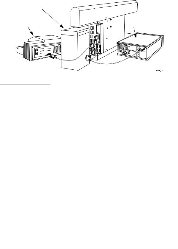
Wash Unit |
|
Plate Reader |
HCB |
Controller |
Figure 4: Connecting the Biomek
Workstation to the Plate Reader,
Wash Unit, and HCB Controller
Safety Features
An emergency STOP switch is located on the front of the worksurface. Use the Stop switch at the base of the workstation if an emergency stop is required. Pressing this switch will freeze the workstation (but not the Side Loader).
Click on the Stop button on the BioWorks Run window to stop the instrument if the stop is not an emergency.
1-8 |
Biomek 2000 |

Chapter 1 |
User’s Guide |
|
|
Document 609909-AA |
|
|
|
|
Stop Button
Figure 5: Emergency Stop Switch
CAUTION
Never attempt to physically restrict the movement of the head and bridge assembly or to exchange labware, reagents, or tools while the instrument is operating, as indicated by the amber safety light at the end of the bridge. Use the Stop switch at the base of the workstation if an emergency stop is required.
Biomek 2000 |
1-9 |

User’s Guide |
Chapter 1 |
Document 609909-AA |
|
|
|
1-10 |
Biomek 2000 |
Loading...