


 Loading...
BE-IM-9
Allegra® 6 Series
and Spinchron™ R Centrifuges
Instruction Manual
Symbol Simbolo
Symbol
Symbole
Símbolo
!
Title |
/ |
Titel |
/ |
Titre |
/ |
Titulo |
/ |
Titolo |
/ |
/ |
Dangerous voltage
Gefährliche elektrische Spannung
Courant haute tension
Voltaje peligroso
Pericolo: alta tensione
Attention, consult accompanying documents
Achtung! Begleitpapiere beachten!
Attention, consulter les documents joints
Atención, consulte los documentos adjuntos
Attenzione: consultare le informazioni allegate
On (power)
Ein (Netzverbindung)
Marche (mise sous tension)
Encendido
Acceso (sotto tensione)
Off (power)
Aus (Netzverbindung)
Arrêt (mise hors tension)
Apagado
Spento (fuori tensione)
Protective earth (ground)
Schutzleiteranschluß
Liaison à la terre
Puesta a tierra de protección
Collegamento di protezione a terra
Earth (ground)
Erde
Terre
Tierra
Scarica a terra

!SAFETY NOTICE
This safety notice summarizes information basic to the safe operation of the equipment described in this manual. The international symbol displayed above is a reminder that all safety instructions should be read and understood before installation, operation, maintenance, or repair of this centrifuge. When you see the symbol on other pages, pay special attention to the safety information presented. Observance of safety precautions will also help to avoid actions that could damage or adversely affect the performance of the centrifuge.
Safety During Installation and/or Maintenance
This centrifuge weighs 51.7 kg/114.0 lb (nonrefrigerated benchtop), 75.8 kg/167.0 lb (refrigerated benchtop), or 90.3 kg/199.0 lb (refrigerated kneewell). DO NOT attempt to lift or move it without assistance from another person.
Be sure to use the anchoring system to secure the centrifuge in place. The anchoring system is designed to reduce the possibility of injury or damage that could result from centrifuge movement in the event of a major rotor mishap.
Any servicing of this equipment that requires removal of any covers can expose parts which involve the risk of electric shock or personal injury. Make sure that the power switch is off and the centrifuge is disconnected from the main power source, and refer such servicing to qualified personnel.
Do not replace any centrifuge components with parts not specified for use on this instrument.
Electrical Safety
To reduce the risk of electrical shock, this equipment uses a three-wire electrical cord and plug to connect the centrifuge to earth-ground. To preserve this safety feature:
•Make sure that the matching wall outlet receptacle is properly wired and earthgrounded. Check that the line voltage agrees with the voltage listed on the name-rating plate affixed to the centrifuge.
•Never use a three-to-two wire plug adapter.
•Never use a two-wire extension cord or a two-wire non-grounding type of multipleoutlet receptacle strip.
Do not place containers holding liquid on or near the chamber door. If they spill, liquid may get into the centrifuge and damage electrical or mechanical components.
Safety Against Risk of Fire
Certain electrical circuits within this equipment are protected by fuses against overcurrent conditions. For continued protection against the risk of fire, replace only with the same type and rating specified.
This centrifuge is not designed for use with materials capable of developing flammable or explosive vapors. Do not centrifuge such materials (such as chloroform or ethyl alcohol) in this centrifuge nor handle or store them within the 30-cm (1-ft) area surrounding the centrifuge.
Mechanical Safety
For safe operation of the equipment, observe the following:
•Use only the rotors and accessories designed for use in this centrifuge.
•Before starting the centrifuge, make sure that the rotor tie-down nut (or rotor lid knob) is securely fastened.
•Do not exceed the maximum rated speed of the rotor in use.
•NEVER attempt to slow or stop the rotor by hand.
•Do not lift or move the centrifuge while the rotor is spinning.
•NEVER attempt to override the door interlock system while the rotor is spinning.
•Maintain a 7.6-cm (3-in.) clearance envelope around the centrifuge while it is running. During operation you should come within the envelope only to adjust instrument controls, if necessary. Never lean on the centrifuge or place items on the centrifuge while it is operating.
Chemical and Biological Safety
Normal operation may involve the use of solutions and test samples that are pathogenic, toxic, or radioactive. Such materials should not be used in this centrifuge, however, unless all necessary safety precautions are taken.
•Observe all cautionary information printed on the original solution containers prior to their use.
•Handle body fluids with care because they can transmit disease. No known test offers complete assurance that they are free of micro-organisms. Some of the most virulent— Hepatitis (B and C) and HIV (I–V) viruses, atypical mycobacteria, and certain systemic fungi—further emphasize the need for aerosol protection. Handle other infectious samples according to good laboratory procedures and methods to prevent spread of disease. Because spills may generate aerosols, observe proper safety precautions for aerosol containment. Do not run toxic, pathogenic, or radioactive materials in this centrifuge without taking appropriate safety precautions. Biosafe containment should be used when Risk Group II materials (as identified in the World Health Organization Laboratory Biosafety Manual) are handled; materials of a higher group require more than one level of protection.
•Dispose of all waste solutions according to appropriate environmental health and safety guidelines.
It is your responsibility to decontaminate the centrifuge and accessories before requesting service by Beckman Coulter Field Service.
BE-IM-9
February 2008
Allegra® 6 Series
and Spinchron™ R Centrifuges
Instruction Manual
© 2008 Beckman Coulter, Inc.

Contents
Page
INTRODUCTION
Certification . . . . . . . . . . . . . . . . . . . . . . . . . . . . . . . . . . . . . . . . . . . . . v Scope of Manual. . . . . . . . . . . . . . . . . . . . . . . . . . . . . . . . . . . . . . . . . . v Conventions . . . . . . . . . . . . . . . . . . . . . . . . . . . . . . . . . . . . . . . . . . . . . . vi Notes, Cautions, and Warnings . . . . . . . . . . . . . . . . . . . . . . . . . . . . vi CFC-Free Centrifugation. . . . . . . . . . . . . . . . . . . . . . . . . . . . . . . . . . . vii Radio Interference . . . . . . . . . . . . . . . . . . . . . . . . . . . . . . . . . . . . . . . . vii Canadian Regulations . . . . . . . . . . . . . . . . . . . . . . . . . . . . . . . . . . viii
Recycling Label . . . . . . . . . . . . . . . . . . . . . . . . . . . . . . . . . . . . . . . . . . viii
SECTION 1: DESCRIPTION
Centrifuge Function and Specifications . . . . . . . . . . . . . . . . . . . . . . . . 1-1
Centrifuge Function . . . . . . . . . . . . . . . . . . . . . . . . . . . . . . . . . . . . 1-1
Allegra 6 and Spinchron Models . . . . . . . . . . . . . . . . . . . . . . . . . . 1-1
Specifications. . . . . . . . . . . . . . . . . . . . . . . . . . . . . . . . . . . . . . . . . 1-3
Available Rotors. . . . . . . . . . . . . . . . . . . . . . . . . . . . . . . . . . . . . . . . . . 1-4
Safety Features . . . . . . . . . . . . . . . . . . . . . . . . . . . . . . . . . . . . . . . . . . . 1-5
Name Rating Plate . . . . . . . . . . . . . . . . . . . . . . . . . . . . . . . . . . . . . . . . 1-6
Chassis . . . . . . . . . . . . . . . . . . . . . . . . . . . . . . . . . . . . . . . . . . . . . . . . . 1-6
Housing . . . . . . . . . . . . . . . . . . . . . . . . . . . . . . . . . . . . . . . . . . . . . 1-6
Door . . . . . . . . . . . . . . . . . . . . . . . . . . . . . . . . . . . . . . . . . . . . . . . . 1-6
Rotor Chamber. . . . . . . . . . . . . . . . . . . . . . . . . . . . . . . . . . . . . . . . 1-6
Drive . . . . . . . . . . . . . . . . . . . . . . . . . . . . . . . . . . . . . . . . . . . . . . . 1-7
Refrigeration System . . . . . . . . . . . . . . . . . . . . . . . . . . . . . . . . . . . 1-7
Controls and Indicators . . . . . . . . . . . . . . . . . . . . . . . . . . . . . . . . . . . . 1-8
Control Panel . . . . . . . . . . . . . . . . . . . . . . . . . . . . . . . . . . . . . . . . . 1-8
SECTION 2: INSTALLATION REQUIREMENTS
Space and Location Requirements . . . . . . . . . . . . . . . . . . . . . . . . . . . . 2-1
Electrical Requirements . . . . . . . . . . . . . . . . . . . . . . . . . . . . . . . . . . . . 2-2
Test Run . . . . . . . . . . . . . . . . . . . . . . . . . . . . . . . . . . . . . . . . . . . . . . . . 2-4
SECTION 3: OPERATION
Run Procedures . . . . . . . . . . . . . . . . . . . . . . . . . . . . . . . . . . . . . . . . . . 3-1
Preparation and Loading . . . . . . . . . . . . . . . . . . . . . . . . . . . . . . . . 3-2
Starting a Run . . . . . . . . . . . . . . . . . . . . . . . . . . . . . . . . . . . . . . . . 3-4
Stopping a Run . . . . . . . . . . . . . . . . . . . . . . . . . . . . . . . . . . . . . . . 3-6
iii

Contents
Page
SECTION 4: TROUBLESHOOTING
Shutdown/No-Start Diagnostics. . . . . . . . . . . . . . . . . . . . . . . . . . . . . . 4-1
Other Possible Problems . . . . . . . . . . . . . . . . . . . . . . . . . . . . . . . . . . . 4-2
Emergency Access . . . . . . . . . . . . . . . . . . . . . . . . . . . . . . . . . . . . . . . . 4-4
SECTION 5: CARE AND MAINTENANCE
General Maintenance . . . . . . . . . . . . . . . . . . . . . . . . . . . . . . . . . . . . . . 5-2
Cleaning . . . . . . . . . . . . . . . . . . . . . . . . . . . . . . . . . . . . . . . . . . . . . . . . 5-2
Decontamination . . . . . . . . . . . . . . . . . . . . . . . . . . . . . . . . . . . . . . . . . 5-3
Sterilization and Disinfection. . . . . . . . . . . . . . . . . . . . . . . . . . . . . . . . 5-3
Tube Breakage . . . . . . . . . . . . . . . . . . . . . . . . . . . . . . . . . . . . . . . . . . . 5-3
Speed Calibration . . . . . . . . . . . . . . . . . . . . . . . . . . . . . . . . . . . . . . . . . 5-4
Speed Verification . . . . . . . . . . . . . . . . . . . . . . . . . . . . . . . . . . . . . 5-4
Speed Knob Adjustment . . . . . . . . . . . . . . . . . . . . . . . . . . . . . . . . 5-4
Temperature Knob Adjustment . . . . . . . . . . . . . . . . . . . . . . . . . . . . . . 5-6
Storage and Transport . . . . . . . . . . . . . . . . . . . . . . . . . . . . . . . . . . . . . 5-7
Storage . . . . . . . . . . . . . . . . . . . . . . . . . . . . . . . . . . . . . . . . . . . . . . 5-7
Returning a Centrifuge . . . . . . . . . . . . . . . . . . . . . . . . . . . . . . . . . 5-7
Supply List . . . . . . . . . . . . . . . . . . . . . . . . . . . . . . . . . . . . . . . . . . . . . . 5-8
Replacement Parts . . . . . . . . . . . . . . . . . . . . . . . . . . . . . . . . . . . . . 5-8
Supplies . . . . . . . . . . . . . . . . . . . . . . . . . . . . . . . . . . . . . . . . . . . . . 5-8
Warranty
Illustrations and Tables
Figure 1-1. |
Allegra 6 Centrifuges . . . . . . . . . . . . . . . . . . . . . . . . . . . . . . . . . . . . . . |
1-2 |
Figure 1-2. |
Interior View of the Centrifuge . . . . . . . . . . . . . . . . . . . . . . . . . . . . . . |
1-7 |
Figure 1-3. |
The Control Panel (Nonrefrigerated Model) . . . . . . . . . . . . . . . . . . . . |
1-8 |
Figure 1-4. |
The Control Panel (Refrigerated Models) . . . . . . . . . . . . . . . . . . . . . . |
1-9 |
Figure 2-1. |
Centrifuge Dimensions. . . . . . . . . . . . . . . . . . . . . . . . . . . . . . . . . . . . . |
2-3 |
Figure 4-1. |
Emergency Access . . . . . . . . . . . . . . . . . . . . . . . . . . . . . . . . . . . . . . . . |
4-5 |
Table 4-1. |
Shutdown/No-Start Diagnostics. . . . . . . . . . . . . . . . . . . . . . . . . . . . . . |
4-2 |
Table 4-2. |
Troubleshooting Chart . . . . . . . . . . . . . . . . . . . . . . . . . . . . . . . . . . . . . |
4-3 |
iv

Introduction
CERTIFICATION
To ensure full system quality, Beckman Coulter Allegra® 6 series and Spinchron™ R centrifuges have been manufactured in an ISO 9001 or 13485 facility. They have been designed and tested to be compliant (when used with Beckman Coulter rotors) with the laboratory equipment requirements of applicable regulatory agencies. Declarations of conformity and certificates of compliance are available at www.beckmancoulter.com.
SCOPE OF MANUAL
This manual is designed to familiarize you with the Allegra 6 series and Spinchron R centrifuges, their functions, specifications, operation, and routine operator care and maintenance. We recommend that you read this entire manual, especially the SAFETY NOTICE and
all safety-related information, before operating the centrifuge or performing instrument maintenance.
NOTE
The descriptions and instructions are the same for Allegra 6R and Spinchron R centrifuges. References in this manual to an Allegra 6R model also apply to the Spinchron R model.
•Section 1 contains system specifications and a brief physical and functional description of the centrifuge, including the operating controls and indicators.
•Section 2 provides instructions for installing and connecting the centrifuge.
•Section 3 contains centrifuge operating procedures.
v

Introduction
•Section 4 lists possible malfunctions, together with probable causes and suggested corrective actions.
•Section 5 contains procedures for routine operator care and maintenance, as well as a brief list of supplies and replacement parts.
NOTE
If the centrifuge is used in a manner other than specified in this manual, the safety and performance of this equipment could be impaired. Further, the use of any equipment other than that recommended by Beckman
Coulter has not been evaluated for safety. Use of any equipment not specifically recommended in this manual and/or the appropriate rotor manual is the sole responsibility of the user.
CONVENTIONS
Certain symbols are used in this manual to call out safety-related and other important information. These international symbols may also be displayed on the centrifuge and are reproduced and described below and on the inside of the front cover.
NOTES, CAUTIONS, AND WARNINGS
NOTE
Used to call attention to important information that should be followed during installation, use, or servicing of this equipment.
!CAUTION
Used to indicate a potentially hazardous situation which, if not avoided, may result in minor or moderate injury and/or mechanical damage. It is also used to alert against unsafe practices.
vi
Introduction
!WARNING
Used whenever an action or condition may potentially cause personal injury or loss of life. Mechanical damage may also result.
 WARNING
Indicates high voltage or risk of electric shock. Refer servicing of all areas displaying either symbol to service personnel.
CFC-FREE CENTRIFUGATION
CFC
To ensure minimal environmental impact, no CFCs are used in the manufacture or operation of Allegra 6 series and Spinchron R centrifuges.
RADIO INTERFERENCE
This equipment has been tested and found to comply with the limits for a Class A digital device, pursuant to Part 15 of FCC Rules. These limits are designed to provide reasonable protection against harmful interference when the equipment is operated in a commercial environment. This equipment generates, uses, and can radiate radio frequency energy and, if not installed and used in accordance with this instruction manual, may cause interference to radio communications. Operation of this equipment in a residential area is likely to cause interference, in which case the user will be required to correct the interference at his own expense.
vii
Introduction
CANADIAN REGULATIONS
This equipment does not exceed the Class A limits for radio noise emissions from digital apparatus as set out in the radio interference regulations of the Canadian Department of Communications.
Le présent appareil numérique n’émet pas de bruits radioélectriques dépassant les limites applicables aux appareils numériques de Classe A prescrites dans le reglement sur le brouillage radioelectrique édicté par le Ministère des Communications du Canada.
RECYCLING LABEL
A28219-AA
Note: On the instrument, the triangle background is yellow rather than gray.
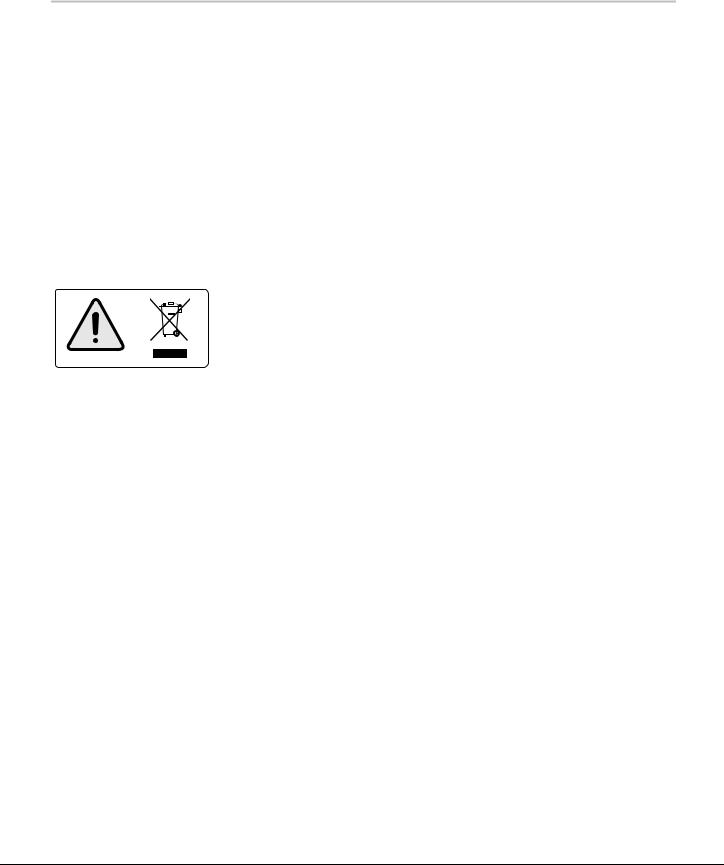
This symbol is required in accordance with the Waste Electrical and Electronic Equipment (WEEE) Directive of the European Union. The presence of this marking on the product indicates.
1)The device was put on the European market after August 13, 2005 and
2)The device is not to be disposed via the municipal waste collection system of any member state of the European Union.
It is very important that customers understand and follow all laws regarding the proper decontamination and safe disposal of electrical equipment. For Beckman Coulter products bearing this label please contact your dealer or local Beckman Coulter office for details on the take back program that will facilitate the proper collection, treatment, recovery, recycling and safe disposal of the device.
viii

1
Description
CENTRIFUGE FUNCTION AND SPECIFICATIONS
CENTRIFUGE FUNCTION
The Beckman Coulter Allegra 6 centrifuge generates centrifugal forces required for a wide variety of applications. Together with the Beckman Coulter rotors designed for use in this centrifuge, the centrifuge applications include:
•Routine processing such as sample preparations, pelleting, extractions, purifications, concentrations, phase separations, receptor binding, and column centrifugations.
•Processing large numbers of small-volume samples in multiwell plates for concentrating tissue-culture cells, cloning and replicate studies, in-vitro cytotoxicity studies, receptor binding, and genetic engineering experimentation.
•Virus isolation.
•Rapid sedimentation of protein precipitates, large particles, and cell debris.
•Preparation of subcellular organelles such as mitochondria, granules, and crude microsomes.
•Binding studies and separation of whole blood.
•Cell isolation.
ALLEGRA 6 AND SPINCHRON MODELS
The Allegra 6 (see Figure 1-1) comes in three models and the
Spinchron in one:
•A nonrefrigerated compact bench model (no Spinchron model)
•A refrigerated compact bench model
•A refrigerated kneewell model (no Spinchron model)
1-1

Description
Allegra 6
Allegra 6R
or
Spinchron R
Allegra 6KR
Figure 1-1. Allegra 6 Centrifuges
1-2

Description
SPECIFICATIONS
Only values with tolerances or limits are guaranteed data. Values without tolerances are informative data, without guarantee.
|
|
|
|
Allegra6R/ |
|
|
|
|
Allegra 6 |
|
Spinchron R |
|
Allegra 6KR |
Speed |
|
|
|
|
|
|
|
|
|
|
|
|
|
Set* (in 200-rpm increments). . |
. . . . . . . 0 to 8000 rpm |
. . . . . . . . . . . . . |
. 0 to 8000 rpm . |
. . . . . . . . . . . . . . . . . |
0 to 8000 rpm |
|
Display . . . . . . . . . . . . . . . . . . . |
. . . ±30 rpm of actual |
. . . . . . . . . . ±30 rpm of actual . |
. . . . . . . . . . . . . . ±30 rpm of actual |
|||
Set time |
|
|
|
|
|
|
Timed run . . . . . . . . . . . . . . . . . |
. . . . . . . . up to 30 min |
. . . . . . . . . . . . . |
. . .up to 30 min . |
. . . . . . . . . . . . . . . . . . |
up to 30 min |
|
Continuous run . . . . . . . . . . . . . |
. . . . . . . . . . . |
. .HOLD |
. . . . . . . . . . . . . |
. . . . . . . HOLD . |
. . . . . . . . . . . . . . . . . . |
. . . . . .HOLD |
Temperature |
|
|
|
|
|
|
Temperature setting |
|
|
|
|
|
|
(refrigerated models only) . . . . |
. . . . . . . not applicable |
. . . . . . . . . . . . . |
. . –10 to 40°C . |
. . . . . . . . . . . . . . . . . . |
. –10 to 40°C |
|
Normal operating range |
|
|
|
|
|
|
(refrigerated models only) . . . . |
. . . . . . . not applicable |
. . . . . . . . . . . . . |
. . . –5 to 25°C . |
. . . . . . . . . . . . . . . . . . |
. . –5 to 25°C |
|
Temperature display |
|
|
actual chamber temp ±2°C |
actual chamber temp ±2°C |
||
(refrigerated models only) . . . . |
. . . . . . . not applicable |
|||||
Ambient temperature range . . . |
. . . . . . . . . 10 to 35°C |
. . . . . . . . . . . . . |
. . . . 10 to 35°C . |
. . . . . . . . . . . . . . . . . . |
. . 10 to 35°C |
|
Ambient temperature range |
|
|
|
|
|
|
for optimum operation . . . . . . . |
. . . . . . . . . 10 to 25°C |
. . . . . . . . . . . . . |
. . . . 10 to 25°C . |
. . . . . . . . . . . . . . . . . . |
. . 10 to 25°C |
|
Humidity restrictions |
<95% (noncondensing) |
. . . . . . <95% (noncondensing) . |
. . . . . . . . . . <95% (noncondensing) |
|||
Dimensions |
|
|
|
|
|
|
Width . . . . . . . . . . . . . . . . . . . . |
. . . 54.6 cm (21.5 in.) |
. . . . . . . . . . . . . |
. 76 cm (30 in.) . |
. . . . . . . . . . . . . . 54.6 cm (21.5 in.) |
||
Depth (overall) . . . . . . . . . . . . . |
. . . 66.0 cm (26.0 in.) |
. . . . . . . . . . . . . |
. 66 cm (26 in.) . |
. . . . . . . . . . . . . . 66.0 cm (26.0 in.) |
||
Depth (at base) . . . . . . . . . . . . . |
. . . 58.0 cm (23.0 in.) |
. . . . . . . . . . . 58.4 cm (23.0 in.) . |
. . . . . . . . . . . . . . 58.4 cm (23.0 in.) |
|||
Height, door closed. . . . . . . . . . |
. . . 40.6 cm (16.0 in.) |
. . . . . . . . . . . 39.4 cm (15.5 in.) . |
. . . . . . . . . . . . . . 67.3 cm (26.5 in.) |
|||
Height, door open . . . . . . . . . . . |
. . . 96.8 cm (38.1 in.) |
. . . . . . . . . . . 94.0 cm (37.0 in.) . |
. . . . . . . . . . . . . 125.7 cm (49.5 in.) |
|||
Weight. . . . . . . . . . . . . . . . . . . . |
. . . 51.7 kg (114.0 lb) |
. . . . . . . . . . 75.8 kg (167.0 lb) . |
. . . . . . . . . . . . . . 90.3 kg (199.0 lb) |
|||
Ventilation clearances |
|
|
|
|
|
|
(sides and rear) . . . . . . . . . . . . . |
. . . . . 7.6 cm (3.0 in.) |
. . . . . . . . . . . . . |
7.6 cm (3.0 in.) . |
. . . . . . . . . . . . . . . . 7.6 cm (3.0 in.) |
||
Electrical requirements . . . . . . . . . . |
. 120 VAC, 8 A, 60 Hz |
. . . . . . 120 VAC, 12 A, 60 Hz . |
. . . . . . . . . . . 120 VAC, 12 A, 60 Hz |
|||
|
230 VAC, 4 A, 50 Hz |
. . . . . . . . 230 VAC, 8 A, 50 Hz . |
. . . . . . . . . . . . 230 VAC, 8 A, 50 Hz |
|||
100 VAC, 10 A, 50/60 Hz |
. . . . . 200 VAC, 10 A, 50/60 Hz . |
. . . . . . . . 200 VAC, 10 A, 50/60 Hz |
||||
Electrical supply . . . . . . . . . . . . . . . |
. . . . . . . . . . . |
. . Class I |
. . . . . . . . . . . . . |
. . . . . . . Class I . |
. . . . . . . . . . . . . . . . . . |
. . . . . .Class I |
Maximum heat dissipation |
|
|
|
|
|
|
into room under |
|
|
|
|
|
|
steady-state conditions . . . . . . . |
3073 Btu/hr (0.9 kW) |
. . . . . . . 5425 Btu/hr (1.59 kW) . |
. . . . . . . . . . 5425 Btu/hr (1.59 kW) |
|||
Noise level 0.91 m (3 ft) |
|
|
|
|
|
|
in front of centrifuge. . . . . . . . . |
. . . . . . . . . . . |
<65 dBa |
. . . . . . . . . . . . . |
. . . . . <65 dBa . |
. . . . . . . . . . . . . . . . . . |
. . . . <65 dBa |
Installation (overvoltage) category . |
. . . . . . . . . . . |
. . . . . II |
. . . . . . . . . . . . . |
. . . . . . . . . . . II . |
. . . . . . . . . . . . . . . . . . |
. . . . . . . . . II |
Pollution degree . . . . . . . . . . . . . . . |
. . . . . . . . . . . |
. . . . . 2† |
. . . . . . . . . . . . . |
. . . . . . . . . . 2† . |
. . . . . . . . . . . . . . . . . . |
. . . . . . . . . 2† |
*Maximum rated speed (depending on rotor in use) can be obtained only at nominal voltages (120 V for 60 Hz; 230 V for 50 Hz; 100 V for 50/60 Hz).
†Normally only nonconductive pollution occurs; occasionally, however, a temporary conductivity caused by condensation must be expected.
1-3
Description
AVAILABLE ROTORS
Refer to the appropriate rotor manuals for complete rotor descriptions.
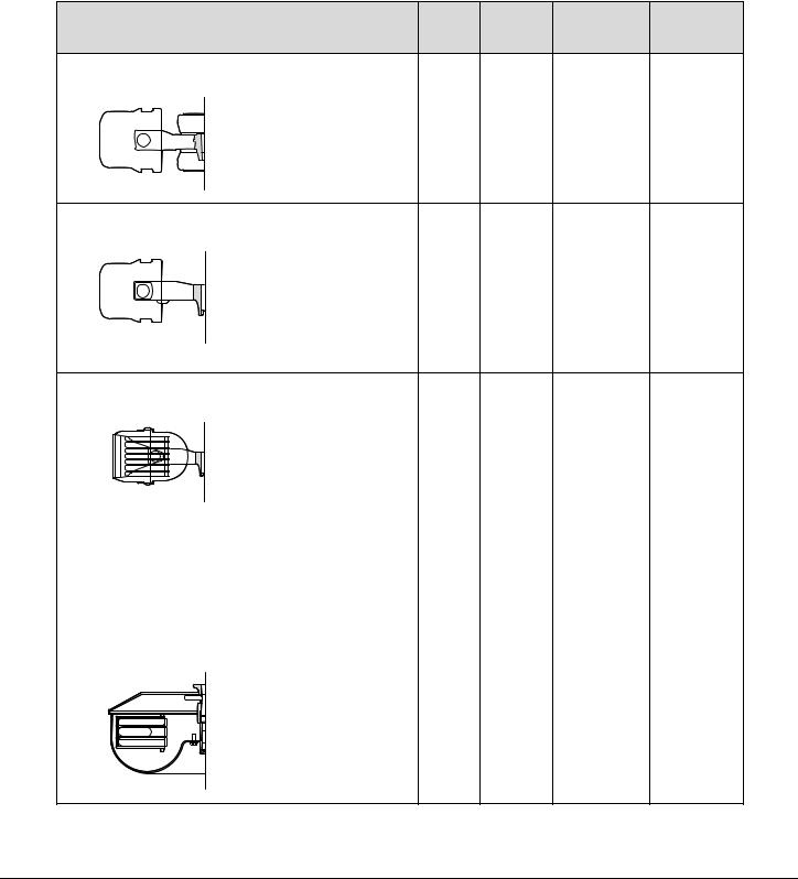
Rotort r Profiler file and Descriptionri ti |
Max |
Max RCF |
Max |
Rotor Manual |
RPM |
(× g) |
Capacity |
Number |
|
GH-3.8A Horizontal (4 place) |
|
|
|
GS6-TB-017 |
Buckets (rmax = 204 mm) |
3750 |
3210 |
4 × 750 mL |
|
Carriers (rmax = 163 mm) |
3250 |
1924 |
4 × 192 mL |
|
GH-3.8 Horizontal (4 place) |
|
|
GS6-TB-003 |
Buckets (rmax = 204 mm) |
3750 |
3210 |
4 × 750 mL |
Carriers (rmax = 163 mm) |
3250 |
1924 |
4 × 192 mL |
PTS-2000 Horizontal (4 place) |
|
|
SP-TB-008 |
||||||
|
|
|
|
|
|
Sector base, 100-mm tube |
3250 |
2010 |
7 × 10 mL |
|
|
|
|
|
|
(rmax = 170 mm) |
|
|
(each carrier) |
|
|
|
|
||||||
|
|
|
|
|
|
Sector base, 75-mm tube |
3250 |
1890 |
7 × 7 mL |
|
|
|
|
|
|
||||
|
|
|
|
|
|
||||
|
|
||||||||
|
|
||||||||
|
|
|
|
|
|
(rmax = 160 mm) |
|
|
(each carrier) |
|
|
|
|
||||||
|
|
|
|
|
|
|
|
||
|
|
|
|
|
|
Tube base, 16-mm tube |
3250 |
2080 |
20 × 10 mL |
|
|
|
|
|
|
(rmax = 176 mm) |
|
|
(each carrier) |
|
|
|
|
|
|
Tube base, 13-mm tube |
3250 |
2080 |
20 × 7 mL |
|
|
|
|
|
|
(rmax = 176 mm) |
|
|
(each carrier) |
|
|
|
|
|
|
Micro Plus carriers |
3250 |
1920 |
4 × 192 mL |
|
|
|
|
|
|
(rmax = 163 mm) |
|
|
|
GH-4.7 Horizontal (4 place) |
|
|
GS-TB-024 |
||||||
|
|
|
|
|
|
(rmax = 182 mm) |
4730 |
4560 |
4 × 250 mL |
|
|
|
|
|
|
|
|
|
|
|
|
|
|
|
|
|
|
|
|
1-4
Loading...