

Page 1

IMMAGE® 800
A11403-AB
March 2004
®
Immunochemistry System
REPEC
Beckman Coulter Ireland, Inc.
Mervue Business Park,
Mervue Galway,
Ireland 353 91 774068
For In Vitro Diagnostic Use
Operations Manual
© Copyright 2004 Beckman Coulter, Inc.
BECKMAN COULTER, INC. • 4300 N. Harbor Blvd., Fullerton, CA U.S.A. 92835
Page 2

TABLE OF CONTENTS
SAFETY NOTICE
CHAPTER 1 General Information/Precautions and Hazards ................................................ 1-1
CHAPTER 2 System Description .......................................................................................... 2-1
CHAPTER 3 Theory of Operations ....................................................................................... 3-1
CHAPTER 4 System Power On/Off ...................................................................................... 4-1
CHAPTER 5 System Setup .................................................................................................... 5-1
CHAPTER 6 Reagents/Calibration ........................................................................................ 6-1
CHAPTER 7 Sample Programming ...................................................................................... 7-1
CHAPTER 8 Results Recall .................................................................................................. 8-1
CHAPTER 9 Quality Control ................................................................................................ 9-1
CHAPTER 10 Utilities ........................................................................................................... 10-1
CHAPTER 11 System Status/Instrument Commands ........................................................... 11-1
APPENDIX A Part Number List ............................................................................................. A-1
APPENDIX B Instrument Codes .............................................................................................B-1
APPENDIX C Reports .............................................................................................................C-1
GLOSSARY
INDEX
IMMAGE 800 Operations Manual A11403 Table of Contents
March 2004 Page 1 of 1
Page 3

Safety Notice
Introduction
This safety notice summarizes information basic to the safe operation of the
IMMAGE® 800 Immunochemistry System described in this manual. The
international symbol displayed above is a reminder that all safety instructions should
be read and understood before installation, operation, maintenance, or repair of this
instrument. When you see the symbol on other pages, pay special attention to the
safety information presented. Observance of safety precautions will also help to avoid
actions that could damage or adversely affect the performance of the instrument.
Other symbols may also be displayed on the equipment. These are reproduced and
described in the Operating Precautions and Hazards section.
Safety During Installation and/or Maintenance
This instrument is designed to be installed by a Beckman Coulter Field Service
representative. Installation by anyone other than authorized Beckman Coulter
personnel invalidates any warranty covering the instrument.
Introduction
Any servicing of this equipment that requires removal of any covers can expose parts
which involve the risk of electric shock or personal injury. Make sure that the power
switch is turned OFF and that the instrument is disconnected from the main power
source. Refer such maintenance to qualified service personnel.
Electrical Safety
• To reduce the risk of electrical shock, this instrument uses a three-wire electrical
cord and plug to connect to earth-ground. Make sure that the matching wall outlet
receptacle is properly wired and earth-grounded.
• Never remove or install any circuit board, connect or disconnect any plug or cable,
while the power is ON. Always use the antistatic wrist strap located in the electronic
board compartment when removing or installing any circuit board.
• Do not place containers holding liquid on top of the instrument. If a spill occurs,
liquid may get into the instrument and damage electrical or mechanical components.
Safety Against Risk of Fire
Fuses protect certain electrical circuits within this instrument against overcurrent
conditions. For continued protection against the risk of fire, replace only with the
same type and rating specified.
IMMAGE 800 Operations Manual A11403 Safety Notice
March 2004 Page 1 of 2
Page 4

Mechanical Safety
Mechanical Safety
For safe operation of the equipment, observe the following:
• Operate the system with reagent door and covers and shields in place.
• During power up, routine operation, and diagnostic procedures, keep hands and/or
foreign objects out of the path of the carousels and probes.
• Do not attempt to clean around the carousels and probes while they are in motion.
Wait until the instrument is in "standby" to perform cleaning procedure.
Chemical and Biological Safety
Normal operation may involve the use of solutions and test samples that are
pathogenic or infectious. Observe all laboratory policies or procedures which pertain
to the handling of these materials.
• The reagents and other chemical preparations used with the system will not
normally cause adverse reactions; however, those persons with sensitive skin should
wear protective gloves before attempting to work with reagents and other chemical
preparations.
• Do not handle sample or solutions without proper protection. Body fluids and other
infectious samples must be handled according to good laboratory practice to prevent
spread of disease.
• When performing maintenance, service, or troubleshooting on elements of the
system that have contacted sera or other biological fluids, observe standard
laboratory precautions. It is always necessary to wash your hands thoroughly after
performing any routine maintenance.
Dispose of all waste solutions according to appropriate environmental health and
safety guidelines.
Safety Notice IMMAGE 800 Operations Manual A11403
Page 2 of 2 March 2004
Page 5

CHAPTER 1 General Information/Precautions and Hazards
Table of Contents
General Information/Precautions and Hazards ........................................................................... 1-2
Introduction ............................................................................................................................. 1-2
How to Use This Manual ........................................................................................................ 1-3
Warranty and Service Policy Information .............................................................................. 1-5
Precautions .............................................................................................................................. 1-6
Hazards .................................................................................................................................... 1-7
Symbols and Labels ................................................................................................................ 1-9
1
IMMAGE 800 Operations Manual A11403 General Information/Precautions and Hazards
March 2004 Page 1-1
Page 6

Introduction
Intended Use
Introduction
Intended Use
The Beckman Coulter IMMAGE® 800 Immunochemistry System is a fully automated,
computer controlled, bench-top analyzer designed for the in vitro quantitation of
biological fluid components and therapeutic drugs. The system methodologies are rate
turbidimetry and rate nephelometry.
The IMMAGE 800 is a high throughput, random access analyzer that features bar code
identification of samples and reagents to perform sample testing. It automatically
dilutes the samples and delivers them to the reaction cuvette along with other reaction
constituents. The system analyzes up to 72 samples per run with up to 24 analytes per
sample.
General Information/Precautions and Hazards
General Information/Precautions and Hazards IMMAGE 800 Operations Manual A11403
Page 1-2 March 2004
Page 7

How to Use This Manual
Scope of This Manual
This manual provides information on the operation of the IMMAGE 800. Diagnostic
interpretation or the clinical significance of the assay results provided by the system
are not discussed in this manual. Typical and actual results are shown only to
demonstrate the operating procedures, parameters, and characteristics of the system.
IMMAGE Chemistry Information Manual
This manual should be used in conjunction with the IMMAGE Immunochemistry
Systems Chemistry Information Manual which contains specific chemistry
information for the full range of analytes available on the IMMAGE 800.
Manual Conventions
The IMMAGE 800 Immunochemistry System Operations Manual uses the following
printed and visual cues to guide the user in how to respond to printed directions.
How to Use This Manual
Scope of This Manual
1
Table 1.1 IMMAGE 800 Conventions
Convention Description
Icon Buttons Icon buttons are in bold with one letter underlined. The
underline indicates which letter to press in combination
with the Alt key to select the icon button from the
keyboard.
Function Buttons [F1] Function buttons are in bold with the corresponding
function key in square brackets ( [ ] ).
<Buttons> The "less than" (<) and "greater than" (>) symbols enclose
a button’s name in bold.
Options button <▼> The "less than" (<) and "greater than" (>) symbols enclose
a black triangle, preceded by the phrase "options button",
all in bold.
Text field Names of text fields are followed by the word "field", all
in bold.
[X], [ → ] or [Tab] Keyboard keys are in bold and enclosed by square
brackets ( [ ] ).
[Alt + X] Combination keys are in bold and enclosed by square
brackets ( [ ] ) with a plus (+) between each key.
Manual Format
Information in this manual is presented in modular units. Each unit of information is
described by a brief title in the left margin.
Many units consist of a table which presents a procedure, process, or description.
IMMAGE 800 Operations Manual A11403 General Information/Precautions and Hazards
March 2004 Page 1-3
Page 8

How to Use This Manual
Procedure Tables
Procedure Tables
Procedure tables are the most common type of table in this manual. They list each step
of a procedure by number with the corresponding action that is to be performed.
A "Refer to Figure x.x." instruction directs the operator to the screen that displays as a
result of the action requested in the step.
Occasionally, a decision must be made at a step within a procedure. A smaller
decision table is then presented which describes the variable conditions in the left
column and the appropriate action for each condition in the right column.
Example of Procedure Table
The following table is an example of a procedure table that contains a decision table.
Step Action
1Select Rerun Samples [F6]. (Refer to Figure x.x.)
2
To enter... type...
individual Sample IDs, the Sample IDs for rerun in the
Sample IDs field.
a range of Sample IDs, the Sample ID at the beginning of
the range in the Range field.
3 Select a button from the bottom of the dialog box.
Read the decision table as complete sentences, using the first heading to introduce the
condition and the second heading to introduce the action. Step 2 of the table is read:
To enter individual Sample IDs, type the Sample IDs for rerun in the Sample IDs
field.
To enter a range of Sample IDs, type the Sample ID at the beginning of the range in the
Range field.
General Information/Precautions and Hazards IMMAGE 800 Operations Manual A11403
Page 1-4 March 2004
Page 9

Warranty and Service Policy Information
Warranty Policy
The IMMAGE 800 Immunochemistry System is covered by and subject to the
exceptions of the standard warranty enclosed with each system. Failure to operate the
system in accordance with this manual voids the warranty.
Service Information
If any fault develops in the system, call the Beckman Coulter Clinical Support Center.
Give full details of the difficulty. Be sure to have the model and serial number (located
on the lower right side of the instrument near the front.)
For USA and Canadian customers only:
Call your local Beckman Coulter office toll-free from anywhere in the continental
United States, Alaska, Hawaii, and Canada at (800) 854-3633.
Warranty and Service Policy Information
Warranty Policy
1
For customers outside the USA and Canada:
Call the nearest Beckman Coulter Field Service Office.
Responsibility During the Warranty Period
The user is responsible for the routine preventive maintenance procedures described in
the maintenance section of this manual. Repairs arising from failure to perform these
maintenance procedures at the indicated time intervals will be made at the user’s
expense.
Shipping Damage
Each IMMAGE 800 System is carefully examined and checked by Beckman Coulter
before it is shipped. When you receive your new IMMAGE 800 System, visually
inspect the shipping container for any possible damage. If there is damage, notify the
Beckman Coulter Service Representative before his/her arrival at your facility to
install your system.
If no damage is found to the shipping container, the Beckman Service Representative
will supervise the unpacking of your system. If it is damaged in any way, the customer
should file a claim with the carrier. If no damage is found, a visual and operational
check of your system will be performed.
IMMAGE 800 Operations Manual A11403 General Information/Precautions and Hazards
March 2004 Page 1-5
Page 10

Precautions
Introduction
Precautions
Introduction
The operational precautions below enable the user to avoid those actions which could
result in an invalid quantitative determination.
Proper Handling of Diskettes
The 3.5 inch floppy diskettes require special handling to prevent damage.
• Do not store or place a diskette near electrical motors, power supplies, or generators.
• Do not store or place a diskette near magnets or a magnetic field.
Proper Handling of Compact Disks
Compact disks (CD-ROMs) require special handling to prevent damage.
• Do not place a CD-ROM in direct sunlight or excessive heat or humidity.
• Hold a CD-ROM by the edges.
• Replace a CD-ROM in its case after use.
Sample Volumes
Sample containers must contain an adequate volume of test specimen to ensure
accurate aspiration. Refer to the IMMAGE Immunochemistry Systems Chemistry
Information Manual and the Sampling Template for information regarding volume
requirements.
CAUTION
Use extreme care when removing bar coded or labeled glass sample tubes from the
IMMAGE 800 sample racks to avoid breakage. Rotating the tube slightly while
pushing from the bottom of the tube may make removal easier.
General Information/Precautions and Hazards IMMAGE 800 Operations Manual A11403
Page 1-6 March 2004
Page 11

Hazards
Introduction
The following hazards are identified to ensure maximum safety of the user.
Booting Up
Close reagent and sample carousel covers and keep clear of all mechanical assemblies
when booting up the system.
Three-pronged Power Plugs
The three-pronged power plug from all system components of the IMMAGE 800
Immunochemistry System must be connected to a three-wire grounded power source.
• Do not use an adapter to connect the power plug to a two-pronged outlet.
• If the electrical outlet will not accept the three-pronged plug, notify qualified
maintenance personnel; they will supply the required electrical ground.
Hazards
Introduction
1
DO NOT UNDER ANY CIRCUMSTANCES OPERATE THE SYSTEM UNTIL AN
ELECTRICAL GROUND IS PROVIDED AND THE POWER CORD IS PROPERLY
CONNECTED TO GROUND.
Emergency Stop
Turn the instrument main power switch off if the stop button on the screen is
unavailable, and the instrument must be stopped immediately.
Cranes
Keep clear of both cranes while the instrument is running.
Covers
Keep all covers and shields in place while the instrument is running.
Adding Samples to an Operating Instrument
The instrument status must be in Standby when adding or changing reagents, buffers,
diluents, or dilution segments. The instrument status must be in Standby or Pausing-
OK to load samples when adding or removing samples. Keep reagent and sample
carousel covers closed while the instrument is running.
Pausing the System to Load Samples
If you pause the system to load or remove samples while the system is running, DO
NOT load or remove samples until the OK to load samples message appears on the
screen. Failure to comply may cause personal injury.
IMMAGE 800 Operations Manual A11403 General Information/Precautions and Hazards
March 2004 Page 1-7
Page 12

Hazards
Replacing Mechanical or Electrical Parts
Replacing Mechanical or Electrical Parts
Before replacing any defective mechanical or electrical part in the system, confirm that
the power to the system is turned off.
Bar Code Readers
DO NOT tamper with or remove the housing of any bar code reader.
Disposal of Waste Liquids
All waste liquids from the IMMAGE 800 Immunochemistry System should be
disposed of in an approved method for handling biohazardous material.
Biological Samples
Observe all laboratory policies or procedures pertaining to the handling of biological
samples that may contain pathogens.
Preservatives
Sodium azide preservative may form explosive compounds in metal drain lines. See
National Institute for Occupational Safety and Health bulletin: Explosive Azide
Hazards (8/16/76).
Incineration of used reagent cartridges may produce toxic fumes.
General Information/Precautions and Hazards IMMAGE 800 Operations Manual A11403
Page 1-8 March 2004
Page 13

Symbols and Labels
Introduction
The following list of symbols and labels is used on the IMMAGE 800
Immunochemistry System. The symbols are affixed to the appropriate components of
the system as described briefly below.
Instrument or Uninterruptible Power Supply (UPS) Power Switch, ON
This symbol is located on the instrument and the UPS main power switches. When the
portion of the switch that displays this symbol is depressed, the instrument is ON.
Instrument or UPS Power Switch ON
Symbols and Labels
Introduction
1
Instrument or UPS Power Switch, OFF
This symbol is also located on the instrument and the UPS main power switches.
When the portion of the switch that displays this symbol is depressed, the instrument is
OFF.
Instrument or UPS Power Switch OFF
Computer Power Switch
This symbol is located above the computer power button. A green light indicates the
power to the computer is ON.
Computer Power Switch
IMMAGE 800 Operations Manual A11403 General Information/Precautions and Hazards
March 2004 Page 1-9
Page 14
Symbols and Labels
Monitor Power Switch
Monitor Power Switch
This symbol is located on the monitor power button. A green light indicates the power
to the monitor is ON.
Printer Power Switch
This symbol is located beside the printer power button. A green light indicates the
power to the printer is ON.
Monitor Power Switch
Printer Power Switch
Connection Between Computer and Mouse
This symbol is located beside the connection between the computer and the mouse.
Computer - Mouse Connection
Connection Between Computer and Keyboard
This symbol is located beside the connection between the computer and the keyboard.
Computer - Keyboard Connection
Connection Between Computer and Printer
This text is located next to the connection between the computer and the printer.
Parallel
General Information/Precautions and Hazards IMMAGE 800 Operations Manual A11403
Page 1-10 March 2004
Page 15

Connection Between Computer and Monitor
This symbol is located beside the connection between the computer and the monitor.
Computer - Monitor Connection
High Voltage - Electric Shock Risk
This symbol indicates high voltage or risk of electric shock.
Connection Between Computer and Monitor
Symbols and Labels
1
Read Manual
This symbol cautions that the manual should be read before using the system.
General Biohazard Caution
This symbol is the international symbol for biohazardous material.
High Voltage - Electric Shock Risk
Read Manual
Biohazard Label
IMMAGE 800 Operations Manual A11403 General Information/Precautions and Hazards
March 2004 Page 1-11
Page 16
Symbols and Labels
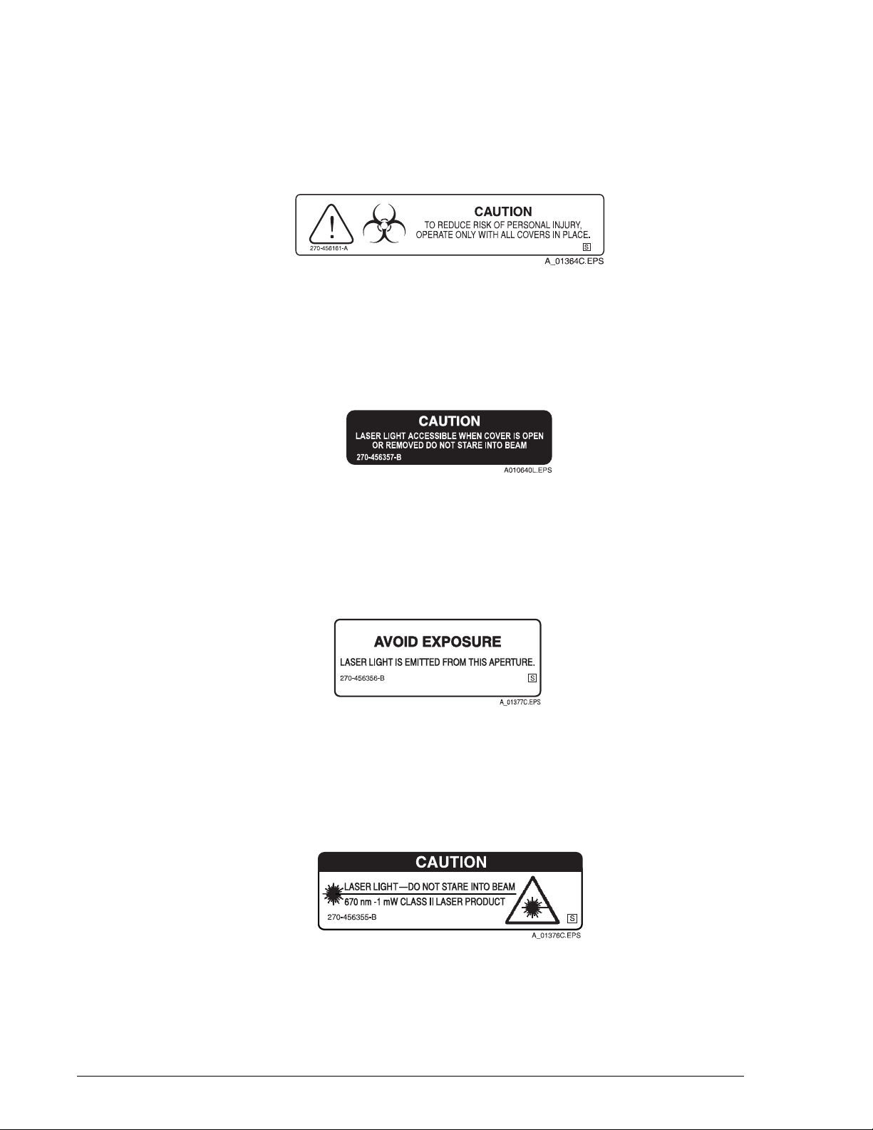
Caution Biohazard
Caution Biohazard
This cautionary label is located between the sample and reagent carousels. Operate
the system with all covers in place.
Bar Code Caution
This label is placed on the cover of any laser-based bar code reader. Do not stare into
laser light beam when cover is open or removed.
Caution Biohazard Label
Laser
This label is placed near any opening through which a bar code reading beam emits.
Avoid exposure to laser light emitted from the opening.
Class II Laser Caution
This cautionary label is located between the sample and reagent carousels. Do not
stare into laser light beam.
Bar Code Caution Label
Laser Caution Label
Class II Laser Caution Label
General Information/Precautions and Hazards IMMAGE 800 Operations Manual A11403
Page 1-12 March 2004
Page 17
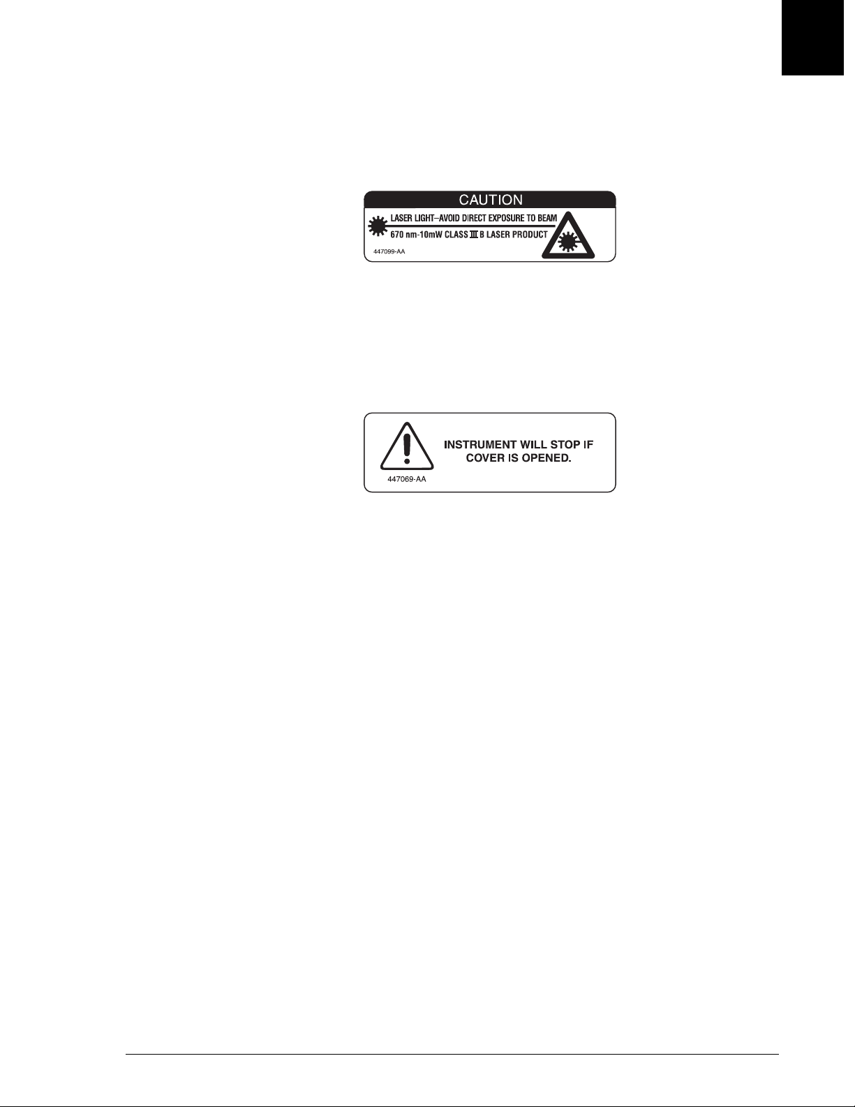
Class III B Laser Caution
This cautionary label is located at the top of the optics module. Avoid direct exposure
to laser light beam.
Reagent Compartment Cover Notice
This label is located on the reagent compartment cover. The instrument will stop if the
cover is opened.
A010648L.EPS
Class III B Laser Caution Label
Symbols and Labels
Class III B Laser Caution
1
A010647L.EPS
Reagent Compartment Cover Label
IMMAGE 800 Operations Manual A11403 General Information/Precautions and Hazards
March 2004 Page 1-13
Page 18

CHAPTER 2 System Description
Table of Contents
Hardware Components ............................................................................................................... 2-2
Overview ................................................................................................................................. 2-2
Instrument ............................................................................................................................... 2-3
Reagent Compartment ............................................................................................................. 2-4
Reagent Crane ......................................................................................................................... 2-6
Reaction Module ..................................................................................................................... 2-8
Sample Carousel ................................................................................................................... 2-10
Sample Crane ........................................................................................................................ 2-12
Upper Instrument Subsystems .............................................................................................. 2-14
Wash Solution Box and Waste Container ............................................................................. 2-17
Racks ..................................................................................................................................... 2-19
Computer ............................................................................................................................... 2-21
Printer .................................................................................................................................... 2-25
Software Overview ................................................................................................................... 2-26
Overview ............................................................................................................................... 2-26
Screen Format ....................................................................................................................... 2-27
Text Fields ............................................................................................................................. 2-30
Buttons .................................................................................................................................. 2-31
Toggle Buttons ...................................................................................................................... 2-32
Check Boxes ......................................................................................................................... 2-33
Performing Software Functions ............................................................................................ 2-34
Selecting vs. Choosing .......................................................................................................... 2-36
Dialog Boxes ......................................................................................................................... 2-37
Deleting Data From a Text Field and Printing Data from a Screen ...................................... 2-38
Page Up/Page Down ............................................................................................................. 2-39
Program Structure ................................................................................................................. 2-40
Sample Programming Overview ........................................................................................... 2-45
System Specifications and Characteristics ............................................................................... 2-46
Instrument Specifications ......................................................................................................2-46
Peripheral Devices Specifications ........................................................................................ 2-48
Sample Container Information .................................................................................................. 2-49
Sample Containers Allowed .................................................................................................. 2-49
Bar Code Types and Options ................................................................................................ 2-50
Bar Code Label Specifications .............................................................................................. 2-52
Applying Bar Code Labels .................................................................................................... 2-54
Sample Volume ..................................................................................................................... 2-55
Loading Tubes Into Racks .................................................................................................... 2-56
Instrument Operation Overview .............................................................................................. 2-57
Instrument Operation ............................................................................................................ 2-57
2
IMMAGE 800 Operations Manual A11403 System Description
March 2004 Page 2-1
Page 19
Overview
Introduction
Overview
Introduction
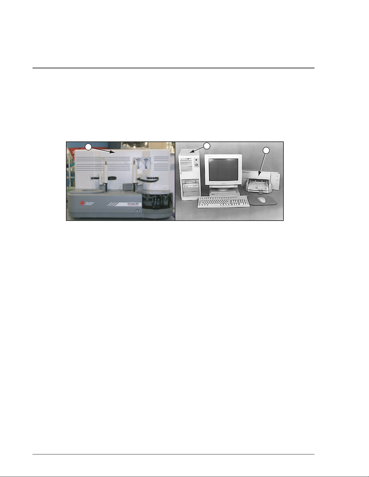
Hardware Components
The IMMAGE® 800 Immunochemistry System is a bench-top analyzer composed of
the IMMAGE 800 instrument, computer and printer. (Refer to Figure 2.1.) The
system is shipped complete for installation. The system will be installed by a
Beckman Coulter Representative.
1
1. Instrument
2. Computer
3. Printer
2
Figure 2.1 The IMMAGE 800 Immunochemistry System
3
A011408P.EPS
System Description IMMAGE 800 Operations Manual A11403
Page 2-2 March 2004
Page 20
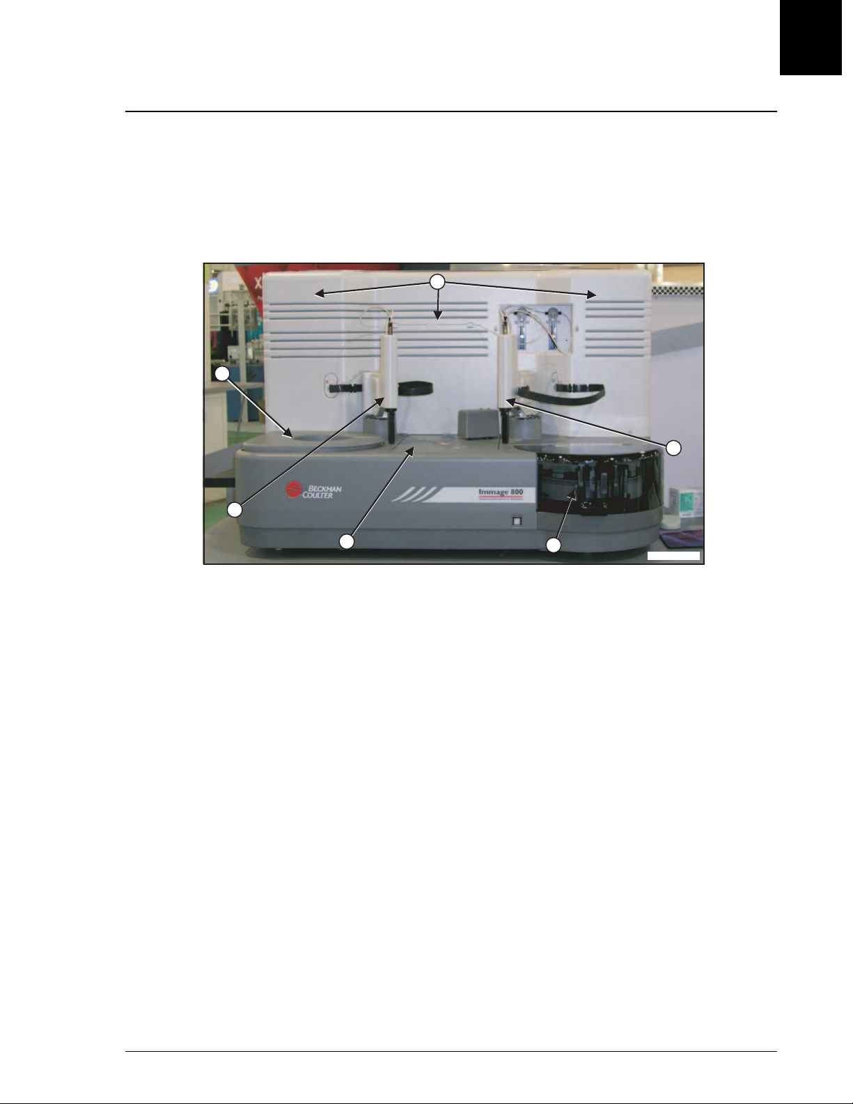
Instrument
Description
The IMMAGE 800 instrument is the analytical unit where the samples and reagents
are loaded and where the chemical reactions take place.
(Refer to Figure 2.2.)
Instrument
Description
6
1
2
2
3
1. Reagent Compartment
2. Reagent Crane
3. Reaction Module
4. Sample Carousel
5. Sample Crane
6. Upper Instrument Subsystems
Figure 2.2 IMMAGE 800 Instrument
5
4
A011409P.EPS
IMMAGE 800 Operations Manual A11403 System Description
March 2004 Page 2-3
Page 21
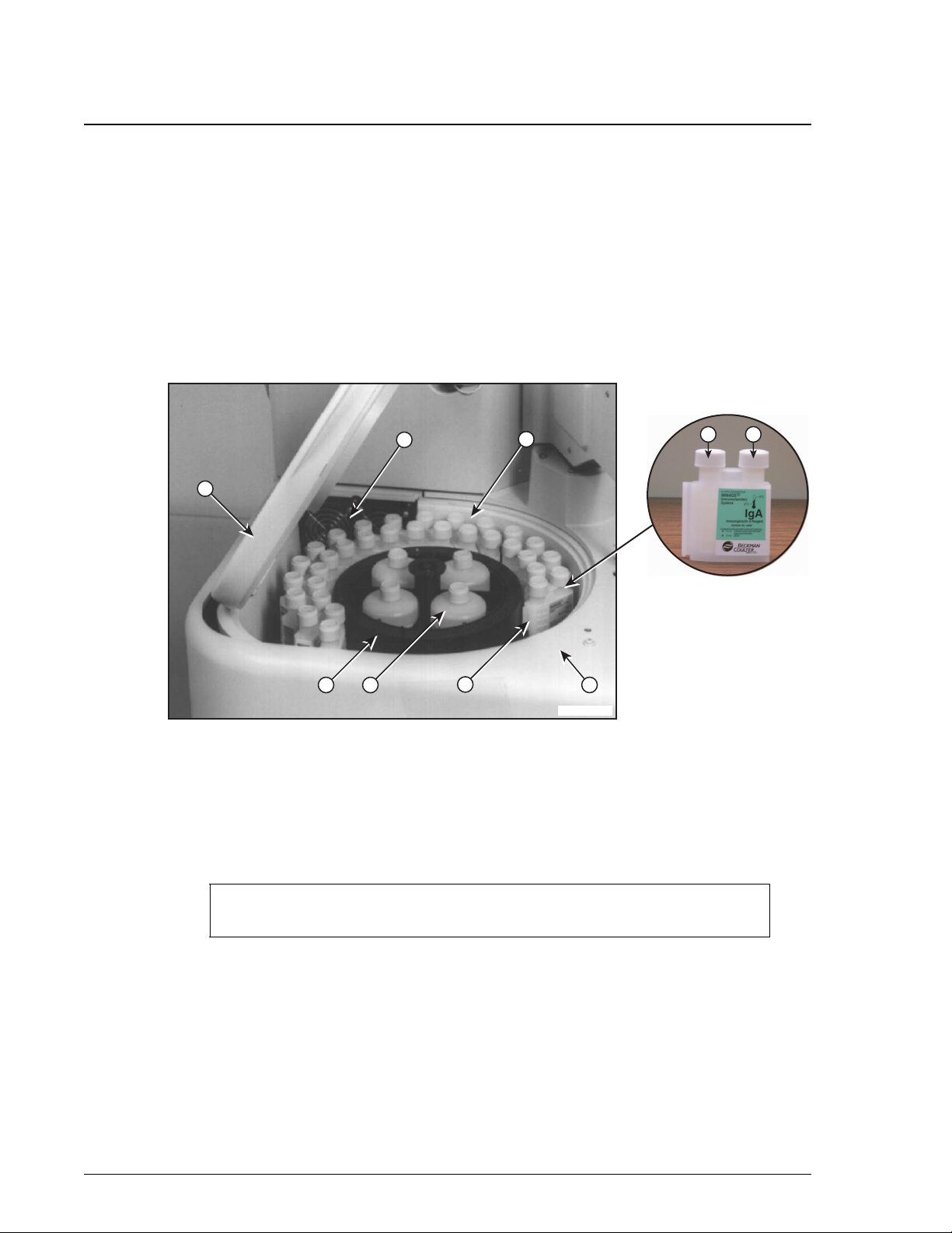
Reagent Compartment
Description
Reagent Compartment
Description
The reagent compartment is the area of the instrument where the removable reagent
carousel is stored. The temperature of the compartment is maintained at
approximately 15°C. (Refer to System Specifications and Characteristics,
"Temperature and Humidity" in this chapter.)
Reaction buffer bottles are placed in the center of the reagent compartment. The
bottles are maintained at room temperature. (Refer to Figure 2.3.)
1
A
6
77
B
2
3
1. Reagent Compartment Cover
2. Reagent Carousel
3. Reaction Buffer Bottle
4. Reagent Cartridges (Compartments A and B)
4
Figure 2.3 The Reagent Compartment
NOTICE
The instrument will stop if the reagent compartment cover is opened.
5
A011410P.EPS
5. Reagent Bar Code Reader
6. Fans
7. Temperature Sensor
System Description IMMAGE 800 Operations Manual A11403
Page 2-4 March 2004
Page 22

Component List
The following table lists each component of the reagent compartment with its
function.
Table 2.1 Reagent Compartment Components
Number Component Function
Reagent Compartment
Component List
2
1 Reagent Compartment
Cover
Necessary to maintain temperature within
compartment.
2 Reagent Carousel Holds up to 24 reagent cartridges and 4 reaction
buffer bottles.
3 Reaction Buffer
Contain reaction buffers.
Bottles
4 Bar Coded Reagent
Cartridges
Contain chemistry specific reagent including
(where applicable):
• Reagent
• AGXS (antigen excess) Solution
• Co-reagent
• Conjugate
• Evaporation Caps
The cartridges are bar coded to allow for
instrument identification of each cartridge.
5 Reagent Bar Code
Reads bar codes on reagent cartridges.
Reader
6 Fans Circulate cool air in reagent compartment.
7 Peltier Temperature
Helps control 15°C in reagent compartment.
Sensor
IMMAGE 800 Operations Manual A11403 System Description
March 2004 Page 2-5
Page 23

Reagent Crane
Description
Reagent Crane
Description
The reagent crane transfers reagents and buffers from the reagent compartment to the
reaction wheel. (Refer to Figure 2.4.)
1. Reagent Probe/Mixer
2. Reagent Syringe Pump
3. Reagent Crane Wash Station
4. Reagent Addition Ports
Figure 2.4 Reagent Crane
System Description IMMAGE 800 Operations Manual A11403
Page 2-6 March 2004
Page 24

Component List
The following table lists each component of the reagent crane with its function.
Table 2.2 Reagent Crane Components
Number Component Function
Reagent Crane
Component List
1 Reagent Probe Aspirates reagents and buffer from the reagent
compartment and dispenses them into a cuvette
on the reaction wheel.
Reagent Paddle Mixer Mixes the contents of a cuvette after reagent or
buffer has been dispensed.
2
2 Reagent Syringe
Pump (500 µL)
3 Reagent Crane Wash
Station
4 Reagent Addition
Ports
Mechanism for accurate reagent and buffer
aspiration and delivery through the reagent
probe.
Washes interior and exterior of reagent probe/
mixer.
Two openings in reaction module cover to allow
reagents to be added to one of two different
cuvette locations.
IMMAGE 800 Operations Manual A11403 System Description
March 2004 Page 2-7
Page 25
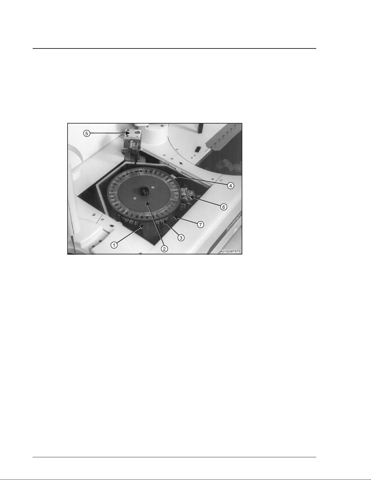
Reaction Module
Description
Reaction Module
Description
The reaction module is the area of the instrument where the reaction takes place. The
temperature of the reaction module is maintained at approximately 37°C. (Refer to
Figure 2.5 and System Specifications and Characteristics, "Temperature and
Humidity" in this chapter.)
1. Optics
2. Reaction Wheel
3. Cuvette
4. Reference Cuvette
Figure 2.5 Reaction Module
5. Cuvette Wash Station
6. Heat Block Temperature Sensor
7. Status Monitor Temperature Sensor
System Description IMMAGE 800 Operations Manual A11403
Page 2-8 March 2004
Page 26

Component List
The following table lists each component of the reaction module with its function.
Table 2.3 Reaction Module Components
Number Component Function
Reaction Module
Component List
1 Optics Measures light scatter in nephelometric
reactions (670 nm wavelength) and
turbidimetric reactions (940 nm wavelength).
2 Reaction Wheel Holds 39 reaction cuvettes and the reference
cuvette. Spins to move individual cuvettes to
correct positions for each stage of the analysis.
3 Cuvettes Hold the combined reactants. The reaction
being measured takes place in the clear, plastic
cuvettes. The optics pass light through the
cuvette to measure scatter.
2
4 Reference Cuvette Has a known scatter value. The instrument
measures the scatter from the on-board
reference cuvette. It then adjusts the optics
based on these measurements and the known
reference values.
5 Cuvette Wash Station Washes the cuvette after the reaction is
complete.
6 Heat Block
Controls 37°C in reaction module.
Temperature Sensor
7 Status Monitor
Monitors reaction module temperature.
Temperature Sensor
IMMAGE 800 Operations Manual A11403 System Description
March 2004 Page 2-9
Page 27
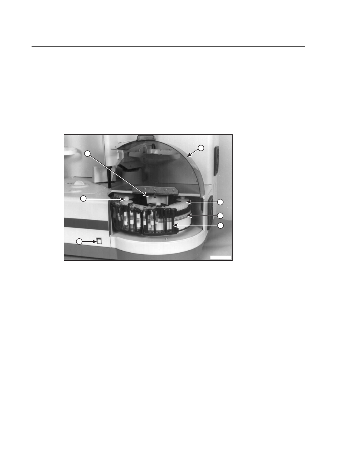
Sample Carousel
Description
Sample Carousel
Description
The sample carousel is the area of the instrument where the samples are loaded onto
the system and where the diluents are placed. Samples are loaded onto the system via
sample racks. All sample cups must be placed on the system using the Sample Cup
Holder Kit. Refer to Appendix A, Part Number List. To ensure sufficient sample
aspiration, do not place sample cups directly into the racks or use 1.0 mL sample cups.
Sample dilutions are made in dilution wells. (Refer to Figure 2.6.)
5
2
6
1. Sample Carousel Cover
2. Sample Diluent Bottle
3. Sample Rack
4. Dilution Segment
Figure 2.6 Sample Carousel
1
4
7
3
A011411P.EPS
5. Sample Bar Code Reader
6. Sample Carousel Advance Button
7. Background Bar Code Label
System Description IMMAGE 800 Operations Manual A11403
Page 2-10 March 2004
Page 28

Component List
The following table lists each component of the sample carousel with its function.
Table 2.4 Sample Carousel Components
Number Component Function
Sample Carousel
Component List
2
1 Sample Carousel
Reduces evaporation of sample.
Cover
2 Sample Diluent
Contain sample diluents.
Bottles
3 Sample Racks Hold sample tubes. (Refer to Racks in this
section of the manual.)
4 Dilution Segments The various sample dilutions are automatically
made in the wells of the dilution segments
before delivery to the reaction wheel. The
disposable dilution segments are placed on the
system by the user.
5 Sample Bar Code
Reader
Scans bar codes on the sample carousel
including:
• bar coded sample tubes
• sample rack bar codes
• background bar codes
• calibrator bar codes
• reagent bar code cards
• calibrator bar code cards
6 Sample Carousel
Advance Button
Rotates the Sample Carousel to allow access for
loading sample racks, dilution segments, and
sample diluent bottles.
7 Background Bar Code
Label
Informs instrument of presence or absence of
sample tube. When the sample bar code reader
can read the background bar code, no sample
tube is present at that position.
IMMAGE 800 Operations Manual A11403 System Description
March 2004 Page 2-11
Page 29
Sample Crane
Description
Sample Crane
Description
The sample crane transfers samples and diluents. Sample dilutions are made in the
dilution wells and then delivered to the reaction wheel. The Sample Crane functions
in the same manner as the Reagent Crane. (Refer to Figure 2.7.)
1. Sample Probe/Mixer
2. Sample Syringe Pump
3. Sample Crane Wash Station
4. Sample Addition Ports
Figure 2.7 Sample Crane
System Description IMMAGE 800 Operations Manual A11403
Page 2-12 March 2004
Page 30

Component List
The following table lists each component of the sample crane with its function.
Table 2.5 Sample Crane Components
Number Component Function
Sample Crane
Component List
1 Sample Probe Aspirates sample and diluent and dispenses
them into the dilution well. Aspirates diluted
sample from the dilution well and dispenses it
into a cuvette on the reaction wheel.
Sample Paddle Mixer Mixes the contents of a cuvette while diluted
sample is dispensed. Also mixes in dilution
wells.
2
2 Sample Syringe Pump
(250 µL)
3 Sample Crane Wash
Station
4 Sample Addition
Ports
Mechanism for accurate sample, diluent, and
diluted sample aspiration and delivery through
the sample probe.
Washes interior and exterior of sample probe/
mixer.
Two openings in reaction module cover to allow
samples to be added to one of two different
cuvette locations.
IMMAGE 800 Operations Manual A11403 System Description
March 2004 Page 2-13
Page 31

Upper Instrument Subsystems
Upper Subsystem List
Upper Instrument Subsystems
Upper Subsystem List
The upper portion of the instrument contains three subsystems.
• Hydro Pneumatics
• Electronics Control Compartment
• Power Supply Assembly
Hydro Pneumatics
The hydro pneumatics control the flow of wash solution through the system and the
flow of waste out of the system. Pressure and vacuum control this fluid motion.
(Refer to Figure 2.8.)
1. Pressure Reservoir-Liquid
2. Pressure Reservoir-Air
3. Vacuum Reservoir
Figure 2.8 Hydro Pneumatics
System Description IMMAGE 800 Operations Manual A11403
Page 2-14 March 2004
Page 32

Electronics Compartment
The electronics compartment contains the electronic circuit boards. (Refer to Figure
2.9.) Electronic circuit boards should only be handled by a Beckman Coulter service
representative.
Upper Instrument Subsystems
Electronics Compartment
2
1. Circuit Boards
Figure 2.9 Electronics Compartment
IMMAGE 800 Operations Manual A11403 System Description
March 2004 Page 2-15
Page 33

Upper Instrument Subsystems
Power Supply Assembly
Power Supply Assembly
All of the power supplies used by the IMMAGE 800 instrument are contained in this
area of the instrument. (Refer to Figure 2.10.) Power supply assemblies should only
be handled by a Beckman Coulter service representative.
1. Power Tower
2. Power Switch
3. Electrical Outlet/Voltage Selector
Figure 2.10 Power Supply Assembly
System Description IMMAGE 800 Operations Manual A11403
Page 2-16 March 2004
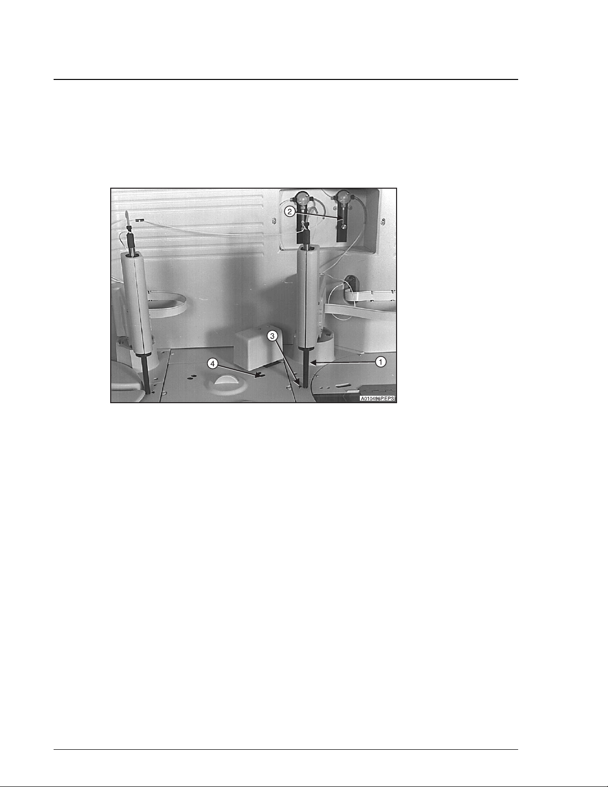
Page 34

Wash Solution Box and Waste Container
Description
The wash solution box and waste container are stored separately from the IMMAGE
800 instrument. (Refer to Figure 2.11.)
Wash Solution Box and Waste Container
Description
2
1. Wash Solution Box
2. Wash Solution Tubing
3. Waste Container
4. Waste Tubing
Figure 2.11 Wash Solution Box and Waste Container
Component List
The following lists the components depicted in Figure 2.11.
Table 2.6 Wash Solution Box and Waste Container Components
Item Component Function
1 Wash Solution Box Holds wash solution.
2 Wash Solution Tubing
(blue and orange)
Blue: Connects wash solution box to
instrument.
Orange: vents wash solution to box.
3 Waste Container Holds waste. (A drain can be used instead.)
4 Waste Tubing (green) Outlet for waste leading to waste container or
drain.
IMMAGE 800 Operations Manual A11403 System Description
March 2004 Page 2-17
Page 35

Wash Solution Box and Waste Container
Wash Solution
Wash Solution
The wash solution is used to wash the probes, mixers, and cuvettes.
Wash Solution Box Placement
The wash solution box must be close enough to the instrument to allow connection of
the wash solution tubing.
Waste Container Placement
The waste container must be placed with the opening of the waste container no higher
than the top of the instrument.
System Description IMMAGE 800 Operations Manual A11403
Page 2-18 March 2004
Page 36

Racks
Description
Description
Each sample rack holds up to nine sample tubes. Each rack is bar coded to allow
identification of the rack number by the instrument. (Refer to Figure 2.12.)
2
3
Racks
2
1. Rack Bar Code Label
2. Rack Number
3. Handle
Figure 2.12 Sample Rack
Types of Racks
There are four types of racks. They are identified by the size of sample tube that they
hold. (Refer to APPENDIX A, Part Number List.)
• 16 × 100 mm
• 16 × 75 mm
• 13 × 100 mm
• 13 × 75 mm
1
A012184P.EPS
Applying Rack Labels
Refer to CHAPTER 5, System Setup, Instrument Setup, Placing Labels on a Rack for a
detailed procedure for label placement.
IMMAGE 800 Operations Manual A11403 System Description
March 2004 Page 2-19
Page 37

Racks
Loading Rack onto the Sample Carousel
Loading Rack onto the Sample Carousel
Follow the steps below to load a rack onto the sample carousel. (Refer to Figure 2.13.)
Step Action
1 Press the Advance button to advance the sample carousel to an empty slot.
2 Lift the rack by its handle.
3 Open the cover of the sample carousel.
4 Align rack pegs over holes in the sample carousel.
5 Lower rack pegs into carousel holes.
Figure 2.13 Loading Rack onto the Sample Carousel
System Description IMMAGE 800 Operations Manual A11403
Page 2-20 March 2004
Page 38

Computer
Description
Computer
Description
The computer supplies the user interface to the IMMAGE 800 Immunochemistry
System and stores data.
The user performs all software interaction on the computer portion of the system. This
software interaction is stored on the computer and is sent to the instrument at the
appropriate time.
Additionally, patient results, control results, and setup parameters are stored on the
computer.
NOTICE
Only the computer supplied by Beckman Coulter is to be used with the IMMAGE 800
Immunochemistry System.
2
Changing the Date on the PC
The PC supplied with some IMMAGE 800 systems contains a battery that provides
power to the computer’s internal clock during power off. The status of the battery is
checked every time the Power On sequence is performed.
The date and time must be reset each time the Power On sequence is performed on a
computer with a dead CMOS (Complementary Metal Oxide Semiconductor) battery.
Contact Beckman Coulter Clinical Support or the nearest local Beckman Coulter Field
Service office for assistance in replacing the battery.
CAUTION
IMMAGE 800 Operations Manual A11403 System Description
March 2004 Page 2-21
Page 39

Computer
Changing the Date on the PC
Table 2.7 Computer Components
Number Component Description
1 Personal Computer
The PC contains the:
(PC)
• CPU (Central Processing Unit)
• hard disk drive
• floppy diskette drive
• CD-ROM Drive
2 Floppy Diskette Drive Where a 3.5 inch floppy diskette is placed and
read.
3 CD-ROM Drive Where a CD-ROM is placed and read.
4 Keyboard 101- key enhanced keyboard.
5 Mouse A two-button movable input device.
6 Monitor Displays user interface (touch screen).
7 Uninterruptible Power
Source (UPS)
The backup power source providing temporary
power to the computer for a limited period of
time in the event of brownouts or low line
voltage conditions.
System Description IMMAGE 800 Operations Manual A11403
Page 2-22 March 2004
Page 40

Keyboard
Figure 2.14 depicts the 101- key enhanced keyboard used on the IMMAGE 800.
Computer
Keyboard
2
1. Escape Key
2. Function Keys
3. Tab Key
4. Caps Lock Key
5. Shift Keys
6. Control Keys
7. Alt Keys
8. Backspace Key
9. Enter Key
10. Delete Key
11. Page Up Key
12. Page Down Key
13. Arrow Keys
Figure 2.14 IMMAGE 800 Keyboard
IMMAGE 800 Operations Manual A11403 System Description
March 2004 Page 2-23
Page 41

Computer
Port Connections
Port Connections
Figure 2.15 shows the back of the computer and where each cable connects.
1
3
2
4
A011412P.EPS
1. Printer Port
2. Monitor Port
3. Mouse/Keyboard Port
4. Instrument Port
Figure 2.15 CPU Ports
Proper Care and Handling of a Floppy Diskette
Diskettes require special care in handling.
• Recommended diskette: 3.5 inch Double-sided, High-density, IBM formatted
diskette.
• Store away from electrical motors, power supplies, or generators.
• Keep away from magnets and magnetic fields.
Proper Care and Handling of a Compact Disk
Compact disks (CD-ROMs) require special care in handling.
• Store away from direct sunlight, excessive heat, and humidity.
• Hold the CD-ROM by the edges.
• Replace the CD-ROM in its case after use.
System Description IMMAGE 800 Operations Manual A11403
Page 2-24 March 2004
Page 42

Printer
Description
Printer
Description
The printer supplied with the IMMAGE 800 Immunochemistry System is the HP
DeskJet printer. The printer is designed to use single sheet paper.
The printer is set up to use 8.5 × 11 inch paper. Paper size can be chosen in Printer
Setup.
Refer to the manual that accompanies the printer for proper setup, care, and handling
of the printer.
2
IMMAGE 800 Operations Manual A11403 System Description
March 2004 Page 2-25
Page 43

Overview
Introduction
Overview
Introduction
Software Overview
The IMMAGE 800 is controlled through a graphical user interface (GUI). This
section describes the basic functions within the interface. The concepts presented in
this section should be understood by the user before attempting to use the IMMAGE
800. The Main Software screen is shown below.
Figure 2.16 Main Screen
E011433S.EPS
System Description IMMAGE 800 Operations Manual A11403
Page 2-26 March 2004
Page 44

Screen Format
Introduction
The IMMAGE 800 Immunochemistry System is designed to have a user friendly
interface. Figure 2.17 shows the sample programming screen of the IMMAGE 800 as
an example of this interface. This screen is broken into six functional areas:
• Status Bar
• Menu Bar
• Title Bar
• Function Buttons
• Message Bar
• Working Area
Screen Format
Introduction
3
2
Status Bar
1
2
4
5
6
1. Status Bar
2. Menu Bar
3. Icon Button
4. Title Bar
5. Function Buttons
6. Message Bar
7. Working Area
Figure 2.17 Sample Programming Screen
7
E011413S.EPS
The blue bar at the top of the screen is the status bar. This bar shows the instrument
status, date and time.
IMMAGE 800 Operations Manual A11403 System Description
March 2004 Page 2-27
Page 45

Screen Format
Menu Bar
Menu Bar
Below the status bar is a row of icon buttons called the menu bar. These icon buttons
can be selected to access various functional areas of the interface. These areas are:
•Main
•Samples
• Results
• Rgts/Cal (Reagent load and calibration)
• QC (Quality control)
•Setup
• Utils (Utilities)
• Status
• Stop - F12
• About
The menu bar consists of these specific icon buttons regardless of the current screen.
Title Bar
Below the menu bar is a bar containing the title of the current screen with some
possible additional information.
Function Buttons
At the bottom of the screen is an area for up to ten function buttons. These function
buttons perform functions that are specific to the particular screen. Each function
button on the screen corresponds to a function key on the keyboard read from left to
right (F1, F2, F3, etc.). The screen function buttons are labeled with the action the
function button performs and the corresponding keyboard function key.
Options Button
Within the working area, and occasionally on screens or dialog boxes, are buttons that
perform a different function than the "F" numbered function buttons. These buttons,
called options buttons, appear triangular in shape (▼) and often accompany a text
field. When an options button is selected, it presents a list of items, or options, from
which a user may choose.
Message Bar
The blue bar at the bottom of the screen is the message bar. This bar is used for
instructions and error messages. The first line displays instructions and the second
line displays error messages. These messages are related to activities in the working
area. (Refer to Figure 2.18.)
System Description IMMAGE 800 Operations Manual A11403
Page 2-28 March 2004
Page 46

Working Area
The middle portion of the screen is referred to as the working area. The user enters
data into the working area via:
•Text fields
• Buttons
• Toggle buttons
• Check boxes
Screen Format
Working Area
5
1
2
3
2
4
E010270S.EPS
1. Text Field
2. Cursor
3. Options Button
4. Toggle Button
5. Check Box
Figure 2.18 Working Area of Program Sample Screen
IMMAGE 800 Operations Manual A11403 System Description
March 2004 Page 2-29
Page 47

Text Fields
Definition of Text Field
Text Fields
Definition of Text Field
Text fields are white areas on the screen in which the user types data.
Definition of Cursor
When a text field is chosen, a cursor displays in that field. This cursor indicates where
text will be entered.
Characteristics of Text Fields
Unless otherwise noted, most text fields can accept any alphanumeric characters. This
means that the user can type in any letter, number, or a space.
Each text field has a limited number of characters that can be entered. Most text fields
have a restricted set of characters that can be entered.
Example: If the user attempts to enter anything other than a number in a numeric field
the character will not be entered. A message will display which reads "Only numeric
characters are allowed."
NOTICE
The alphanumeric characters "|" (piping bar), "\" (backslash), " ^" (caret), and "&"
(ampersand) are not allowed because they are host interface delimiters.
System Description IMMAGE 800 Operations Manual A11403
Page 2-30 March 2004
Page 48

Buttons
Function
Example
Buttons
Function
Buttons on the screen perform as their name implies. When they are selected or
"pressed" an action is performed in the software. Often this action will be used to
access a new screen or dialog box.
The icons in the menu bar and the function buttons on the bottom of the screen operate
like buttons.
The options button <▼> next to the Sample Comment field on the Program Sample
screen is an example of a button.
2
IMMAGE 800 Operations Manual A11403 System Description
March 2004 Page 2-31
Page 49

Toggle Buttons
Function
Toggle Buttons
Function
Toggle buttons function in the same manner as buttons, except when they are selected
or "pressed", their state is changed.
Selected or Unselected
Toggle buttons may either be in the selected or unselected state. If a toggle button is
selected it will be highlighted in blue.
Example
Each chemistry button in the list of chemistries on the Program Sample screen is an
example of a toggle button.
System Description IMMAGE 800 Operations Manual A11403
Page 2-32 March 2004
Page 50

Check Boxes
Function
Check boxes are similar to toggle buttons because they are either toggled on or off.
When selected, a check box will change state.
States
A check box is either checked or unchecked. When checked, a check mark will appear
in the check box.
Example
The STAT check box on the Sample Program screen is an example of a check box.
Check Boxes
Function
2
IMMAGE 800 Operations Manual A11403 System Description
March 2004 Page 2-33
Page 51

Performing Software Functions
Introduction
Performing Software Functions
Introduction
The IMMAGE 800 Immunochemistry System uses a graphical user interface.
Functions can be performed by using a mouse to point and click, with keyboard
equivalents, or with an optional touch screen.
Using the Mouse
The mouse is the recommended method for performing actions with the IMMAGE
800. When the mouse is moved, the arrow on the screen moves with it. This arrow is
called the pointer. Movements of the pointer correspond to movements of the mouse.
When the pointer tip is touching an item on the screen, the pointer is pointing to that
item. Pressing the left button on the mouse and quickly releasing it is called clicking.
Clicking a button on the screen that the pointer is pointing to will select that button.
Clicking twice in rapid succession is called double-clicking. Pressing and holding
down the left mouse button and moving the mouse is referred to as dragging.
Using Keyboard Equivalents
All actions on the IMMAGE 800 can be performed with keyboard equivalents as well.
The screen navigation will be affected by the location of the cursor on the screen. The
cursor movement is directed either within a partition (local movement), which is a
logical grouping of data fields that may or may not be visually distinct from other
groupings, or is directed globally, which is movement throughout the entire screen.
Keyboard equivalent methods include:
• [Alt + Key]
• Function Buttons
• Tabs + Spacebar
• Arrow Keys + Spacebar
• Page Up/Page Down Keys
• Selecting a number from a list
[Alt + Key]
Icon buttons on the menu bar, at the top of the screen, can be selected by pressing and
holding down the [Alt] key and then pressing the key that corresponds to the
underlined letter in the title of that icon. For example, to show the Main screen, press
the key combination [Alt + m]. Buttons in dialog boxes may be selected using the [Alt
+ key] method as well.
Function Buttons
Functions buttons on the bottom of the screen can be selected by pressing the function
keys at the top of the keyboard (F1, F2, F3, ...). The function buttons on the screen are
numbered from left to right just as they are on the keyboard.
System Description IMMAGE 800 Operations Manual A11403
Page 2-34 March 2004
Page 52

Tab + Spacebar
The items in the working area of the screen can be chosen by using the [Tab] key.
Pressing the [Tab] key moves the highlight forward (generally left to right and top to
bottom) through the various text fields and screen buttons that may be chosen. If the
item is a text field, data may be entered as soon as the item is chosen. If the item is a
button, the button can be selected by pressing the [Spacebar].
Arrow Keys + Spacebar
The Arrow Keys on the keyboard may also be used to move the highlight between the
various items on the screen that may be chosen. The highlight moves in the direction
of the arrow. If a text field is chosen, [ ← ] and [ → ] will move through each letter in
the field before moving to the next item. If the item is a text field, data may be entered
as soon as the item is chosen. If the item is a button, the button can be selected by
pressing the [Spacebar].
Page Up/Page Down Buttons
An exception to the use of the [Tab] key or arrow keys are page up/page down buttons.
These buttons cannot be chosen. The [Page Up] and/or [Page Down] keys on the
keyboard are equivalent to the <Page Up> and <Page Down> buttons, respectively.
Performing Software Functions
Tab + Spacebar
2
Selecting a Number from a List
If there is a list of items to choose from, the user may select an item by typing the
number of the item in the text box and pressing [Enter].
A range of numbers can be entered by entering the first number followed by a dash
followed by the last number in the range (Example: 1-5 selects 1, 2, 3, 4, and 5).
A list of discontinuous numbers can be entered by separating the items with a comma
(Example: 1, 5, 8-10 selects 1, 5, 8, 9, and 10).
Using the Touch Screen
When the touch screen is used, the screen can be touched with a finger or any other
object. Any button on the screen can be selected by touching the button on the screen.
Any text field can be chosen by touching the field on the screen.
IMMAGE 800 Operations Manual A11403 System Description
March 2004 Page 2-35
Page 53

Selecting vs. Choosing
Introduction
Selecting vs. Choosing
Introduction
Selecting an item or field is different from choosing the item or field. Text fields can
only be chosen. Buttons, toggle buttons, and check boxes can be chosen and selected.
"Choosing" Definition
Using the [Tab] key or arrow keys moves the user to the various items on the screen by
highlighting one item at a time. An item is highlighted when a dark line appears
around it. When the item is highlighted that item is chosen but no action occurs.
"Selecting" Definition
Pressing the [Spacebar] selects the chosen item on the screen. When an item is
selected the software performs the appropriate action.
Text fields cannot be selected, only chosen.
Selecting/Choosing by Mouse or Touch screen
Buttons, toggle buttons, and check boxes are selected with the user’s first action and
the [Spacebar] is not needed when using the mouse or touch screen.
System Description IMMAGE 800 Operations Manual A11403
Page 2-36 March 2004
Page 54

Dialog Boxes
Definition
Dialog boxes are smaller than the total size of the screen and generally do not include
a bottom row of function keys. The purpose of a dialog box is to input a single piece
of data. This piece of data may be as simple as confirming the user’s request for the
system to perform an action. (Refer to Figure 2.19.)
Data is entered into dialog boxes the same as it is entered into the working area of any
screen.
Dialog Boxes
Definition
2
<Cancel>
<OK>
E010254S.EPS
Figure 2.19 Dialog Box Example
Most dialog boxes will have a <Cancel> button. This button closes the dialog box
without entering the requested data or denies confirmation of an action. If this button
is selected:
• no data is entered
• no action is performed
• the dialog box closes
This button can also be selected by pressing [Alt + c].
Some dialog boxes will have an <OK> button. This button accepts the data being
entered or confirms a user’s request for an action. If this button is selected:
• the data is entered into the system or the action is performed
• the dialog box closes
This button can also be selected by pressing [Alt + o].
<Print> or <Display>
Some dialog boxes may contain <Print> or <Display> buttons.
IMMAGE 800 Operations Manual A11403 System Description
March 2004 Page 2-37
Page 55

Deleting Data From a Text Field and Printing Data from a Screen
Deleting Data from a Text Field
Deleting Data From a Text Field and Printing Data from a Screen
Deleting Data from a Text Field
Follow the steps below to delete data from a text field.
Step Action
1 Choose the text field.
2 Choose one:
• Press the [Delete] key to delete the entire field.
• Press the [Backspace] key to delete a single character prior to the cursor.
• Drag through any portion of the text to highlight it and then press the
[Backspace] key to delete the highlighted text.
Printing Data from a Screen
Many screens contain data that may be printed by selecting Print [F10].
Printing a Screen
Any screen can be printed by pressing [Ctrl] + [P] simultaneously.
System Description IMMAGE 800 Operations Manual A11403
Page 2-38 March 2004
Page 56

Page Up/Page Down
Definition of Multipage
Some screens contain lists of data. If this list contains more data than an individual
screen can show the list is said to be multipage.
Example:
The chemistry list on the Program Sample screen is a multipage list.
Use of Page Up/Page Down
The user can access additional pages of data by selecting the page up and page down
buttons on the right. The page numbers are shown above the buttons. Selecting the
Page Down button will advance the page to the next page. Selecting the Page Up
button will return the page to the previous page. These buttons only appear if more
than one page of data exists.
Page Up/Page Down
Definition of Multipage
2
Keyboard Equivalents
The keyboard equivalent of the screen Page Up and Page Down buttons are the [Page
Up] and [Page Down] keys, respectively.
IMMAGE 800 Operations Manual A11403 System Description
March 2004 Page 2-39
Page 57

Program Structure
Introduction
Program Structure
Introduction
The software or interface of the IMMAGE 800 Immunochemistry System is divided
into functional areas based on different tasks. The icons in the menu bar at the top of
the screen represent the various functional areas. The following menu tree displays an
overview to the structure of the IMMAGE 800 software divided into its functional
groups.
Main
Home
Pause
Run
Samples Control Batch [F1]
Demog [F2] (Demographics) Program Sample [F1]
Save Next [F10]
Sample Options [F3]
Set Variable
OK
Cancel
End Batch [F10]
Select Control [F5] Sample Options [F3]
Select Control [F5]
Clear Chem [F7]
Cancel/Edit [F9]
Save/Next [F10]
Rerun Samples [F6]
Rerun Samples
Rerun Chems
Cancel
Stop
Link Sample
Program Batch [F4] Select Racks [F1]
Edit Samples
Clear Samples [F7]
Post Run Summary [F8]
Load List [F9]
Save/Next [F10]
E011369L.EPS
Figure 2.20 IMMAGE 800 Program Tree (1 of 5)
System Description IMMAGE 800 Operations Manual A11403
Page 2-40 March 2004
Page 58

Results Display Results [F1] Update Sample [F2]
Send to Host [F6]
Report Format [F7]
Print Report [F8]
Prev Sample [F9]
Next Sample [F10]
Cancel Send [F4]
Send to Host [F8]
Report Format [F9]
Print Report [F10]
Rgts/Cal Read Reagent [F1]
(Reagents/
Calibration) Reagent Summary [F2]
Buffer Diluent [F3]
Program Structure
Introduction
2
Request Cal [F4] Clear Racks [F1]
(Request Calibration) Save [F9]
Cancel [F10]
Cal Options [F5]
(Calibration Options)
Slope/Offset Adjustment
Calibrator Summary
Print Last Calibration Results
Cal LdList [F6]
(Calibration Loadlist)
Cancel Request [F7]
Read Cards [F8]
Figure 2.21 IMMAGE 800 Program Tree (2 of 5)
E011370L.EPS
IMMAGE 800 Operations Manual A11403 System Description
March 2004 Page 2-41
Page 59

Program Structure
Introduction
QC Review Control [F1] Control ID [F2]
(Quality Delete Control [F3]
Control) Print Control [F10]
Define/Edit [F2] Add/Del Chems [F1]
Control ID [F2]
Delete Control [F3]
Delete Control [F3]
QC File List [F4] List CtlName [F1]
List File# [F2]
List SelChem [F3]
List AllChem [F4]
Print [F10]
QC Log [F5] QC Log [F1]
Reagent Lot [F2]
Delete Result [F3]
*Action Log [F4]
Print [F10]
QC Summary [F6] Print Inter-Lab [F9]
Print [F10]
QC Chart [F7] Control Chems [F1]
QC File # [F2]
Print [F10]
Figure 2.22 IMMAGE 800 Program Tree (3 of 5)
System Description IMMAGE 800 Operations Manual A11403
Page 2-42 March 2004
Page 60

Program Structure
Introduction
2
Setup
Define PrtName [F3]
(Define Print Name)
Clear All [F4]
Insert Chem [F5]
(Insert Chemistry)
Delete Chem [F6]
(Delete Chemistry)
UDR Main [F9]
Delete Panels [F2] Panels Summary [F2]
Print All [F10] Prev. Panel [F9]
Next Panel [F10]
Select TUrine [F2]
Define Calc [F3]
Delete Calc [F4]
Define Var [F5]
Chemistry
Beckman Chems [F1]
Configuration
Panels
Bar Code
Define/Edit [F1] Clear Chem [F1]
Restore Default [F1]
Reference Interval
Report Setup
Calculations
Restore Default [F1]
View/Edit [F1]
(Beckman Chemistries)
Change Date [F2]
Change Time [F3]
Units/Non-standard Dilutions
Antigen Excess
Date/Time
Host Communications
Restore Default [F1]
Restore Default [F1]
Restore Default [F1]
Default Setup
Restore Default [F1]
Print All [F10]
Sample Comments
Demographics Setup
Printer Setup
Restore Default [F1]
Languages/Keyboard
Chemistry Protocol Diskette
Instrument Serial Number
Figure 2.23 IMMAGE 800 Program Tree (4 of 5)
IMMAGE 800 Operations Manual A11403 System Description
March 2004 Page 2-43
Page 61

Program Structure
Introduction
Utils
Prime
(Utilities)
Event Log
Display Events [F1]
Copy to Disk [F2]
Date/Time [F3]
Clear Events [F4]
Print [F10]
Diagnostics
Cycle Count
Call. Diagnostics
Alignment
Format QNX Diskettes
Prev Align [F1] (Previous Alignment)
Backup/Restore
Wash Cuvettes
Fill Internal Wash
Bottle
Stop Print
Reload DAS Code
Calibrate Touch Screen
Shutdown
Status
Dilution Segments
Sample Carousel Status
Figure 2.24 IMMAGE 800 Program Tree (5 of 5)
System Description IMMAGE 800 Operations Manual A11403
Page 2-44 March 2004
Page 62

Sample Programming Overview
Introduction
This section summarizes the sample programming methods for the IMMAGE 800
Immunochemistry System.
Sample Programming Options
The following table will summarize the sample programming options based on the
variables of bar coded samples and host interface. For detailed explanations of sample
programming refer to CHAPTER 7, Sample Programming, of this manual.
Table 2.8 Sample Programming Options
Sample Programming Overview
Introduction
2
Bar Coded
Samples
Yes Host Query None required. Load samples in any rack and
No Bi-directional None required. Load samples in rack and
Yes Bi-directional None required. Load samples in any rack and
No Unidirectional Required. Enter rack and position number,
Yes Unidirectional Required. Enter sample ID, and chemistries.
No None Required. Enter rack and position number,
Yes None Required. Enter sample ID, demographics, and
Host Interface Sample Programming
position.
position assigned by host.
position.
sample ID, and chemistries. Load samples in
assigned rack and position.
Load samples in any rack and position.
sample ID, demographics, and chemistries.
Load samples in assigned rack and position.
chemistries. Load samples in any rack and
position.
IMMAGE 800 Operations Manual A11403 System Description
March 2004 Page 2-45
Page 63

Instrument Specifications
Placement
System Specifications and Characteristics
Instrument Specifications
Placement
The surface on which the unit rests must be free of vibration and must be level, 1° or
<0.75 inch (1.9 cm) slope across the length and the width of the instrument. Do not
place instrument in direct sunlight or drafts or near a heating or cooling duct.
Clearance
Sides - 6 inches (15.2 cm) minimum
Back - None
Front - 3 inches (7.6 cm) minimum
Top - 4 inches (10.1 cm) from top of instrument
Dimensions (Excluding Wash and Waste Bottles)
Height = 30 inches (76.2 cm)
Depth = 25.5 inches (64.8 cm)
Length = 43.5 inches (110.5 cm)
Weight
250 lb. (120 kg)
Power Requirements
Operating Range 115 (90-132) VAC RMS, Single Phase
Frequency 50/60 Hz nominal (47-63 Hz)
Transient Suppression Recommended
BTU Generated 2,900 BTU/hour
Electrical Outlet Grounded per Local Code
Surge Protector Recommended
Current 8.0 Amps (normal) 12 Amps surge
Temperature and Humidity
Ambient Temperature +15°C to +32°C
Ambient Relative Humidity (RH) 15% to 85% (non-condensing)
Reagent Compartment Temperature 13-22°C (32°C Ambient, <45%RH)
Reaction Module Temperature +37°C ± 0.5°C
230 (180-264) VAC RMS, Single Phase
System Description IMMAGE 800 Operations Manual A11403
Page 2-46 March 2004
Page 64

Drain Requirements
Flow Rate: 3 Liters/hour minimum
Waste Container Placement: The opening should be no higher than the top of the
instrument.
Regulatory Agency Approvals
The IMMAGE 800 meets the safety requirements for the following agencies: CE, UL,
CSA, IEC and CENFLEC.
Environmental Conditions
System can operate up to 8000 ft. (2,438m) elevation.
Capacities
The following table lists various system capacities.
Table 2.9 System Capacities
Instrument Specifications
Drain Requirements
2
Item Capacity
Reagents 24 reagent cartridges can be loaded.
Reagent cartridge 40, 150, or 300 tests per cartridge.
Reaction buffers 4 bottles can be loaded.
Buffer bottle 120 mL: 350 tests.
Samples 72 samples can be loaded.
Sample diluents 4 bottles can be loaded.
Diluent bottles 120 mL: number of dilutions is workload dependent.
Sample dilution segments 4 segments of 36 wells each.
Dilution well 300 µL.
Wash solution 1 box/10 L/approximately 1,000 tests.
Waste container 5 gallons (18.9 L).
IMMAGE 800 Operations Manual A11403 System Description
March 2004 Page 2-47
Page 65

Peripheral Devices Specifications
Introduction
Peripheral Devices Specifications
Introduction
Refer to the inserts which accompany the respective peripheral devices (computer,
printer, etc.) for product specifications.
System Description IMMAGE 800 Operations Manual A11403
Page 2-48 March 2004
Page 66

Sample Container Information
Sample Containers Allowed
Introduction
The following categories document specifications for sample containers that can run
on the IMMAGE 800 Immunochemistry System.
Primary Tubes
16 × 100 mm (10 mL)
16 × 75 mm (7 mL)
13 × 100 mm (7 mL)
13 × 75 mm
16.5 × 92 mm
Secondary (Aliquot) Tubes
16 × 100 mm
16 × 75 mm
13 × 100 mm
12 × 75 mm
Sample Containers Allowed
Introduction
2
Microtubes
13 × 100 mm SYNCHRON® Microtube™
Sample Cups
2 mL (placed into a sample cup holder)
0.5 mL (placed into a sample cup holder)
NOTICE
Low humidity and high ambient temperature may cause evaporation when using small
volumes of sample in sample cups. To minimize evaporation:
• Program samples in positions A or B on the sample carousel.
OR
• Program samples as STATS.
IMMAGE 800 Operations Manual A11403 System Description
March 2004 Page 2-49
Page 67

Bar Code Types and Options
Introduction
Bar Code Types and Options
Introduction
Four bar code types are supported by the IMMAGE 800:
•Code 39
• Code 128
• Interleaved 2 of 5
•Codabar
The bar code scanner will read any of these bar code types, provided the type is
enabled in Bar Code Setup and the options match those defined for the bar code label.
The scanner will also automatically discriminate between the symbologies, so tubes
with bar code labels of different types may be intermixed in a run.
Code 39 Options
Check Digit: If a higher degree of data integrity is required, a check digit may be
enabled and added to the bar code ID. The check digit used is a Modulus 43, which is
the sum of all the character values and is the last digit of the bar code ID. Code 39
expects the check digit to be included in the final code length.
Large Intercharacter Gap: In Code 39, the intercharacter gap has a minimum value of
one times the width of the narrow element and a maximum value of three times the
width of the narrow element, or 0.06 inches (0.152 cm), whichever is greater. This
feature should be enabled when the intercharacter gap exceeds four times the narrow
element width.
Fixed Code Length: If the sample IDs being used are all of the same length, Fixed
Code Length may be enabled to ensure that only one length of sample ID is accepted.
Define Code Length: When Fixed Code Length is enabled, the code length may be
defined as from 1 to 15 characters.
Code 128 Options
The options for Code 128 bar codes are fixed in the software and cannot be
reconfigured by the user. The IMMAGE 800 uses Code 128 formatting to read
BECKMAN COULTER bar coded cards and rack ID.
Fixed Code Length: disabled.
System Description IMMAGE 800 Operations Manual A11403
Page 2-50 March 2004
Page 68

Interleaved 2 of 5 Options
Check Digit: If a higher degree of data integrity is required, a check digit may be
enabled and added to the bar code ID. The check digit used is a Modulus 10.
Interleaved 2 of 5 expects the check digit to be included in the final code length.
Code Length One: An even number from 0 to 14 must be defined as the number of
characters in the code.
Code Length Two: A second code length (an even number from 0 to 14) may be
defined. Both lengths would then be recognized.
Codabar Options
Start and Stop Codes Match: When this option is enabled, the start code and stop code
must be the same character for a valid read.
Large Intercharacter Gap: This option is used when reading Codabar labels with large
gaps between bar code characters. The normal intercharacter gap cannot exceed one
character element.
Bar Code Types and Options
Interleaved 2 of 5 Options
2
Fixed Code Length: If the sample IDs being used are all of the same length, Fixed
Code Length may be enabled to ensure that only one length of sample ID is accepted.
Define Code Length: When Fixed Code Length is enabled, the code length may be
defined as from 1 to 15 characters.
IMMAGE 800 Operations Manual A11403 System Description
March 2004 Page 2-51
Page 69

Bar Code Label Specifications
Industry Standards
Bar Code Label Specifications
Industry Standards
American National Standards (ANSI X3.182.1990)
American Society for Testing Materials (ASTM E1466-92)
Symbol Size
Maximum overall length: 60 mm (2.36 inch)
(Includes bar code symbol with 5 mm (0.20 inch) quiet zone at each end.)
Minimum height: 10 mm (0.40 inch)
Symbol Content
Maximum of 15 characters.
Recommended symbol content printed on label in human-readable form. Square
bracket ([ or ]), percentage sign (%), dollar sign ($), comma (,) quotation mark ("),
ampersand (&), asterisk (*), semi-colon (;), question mark (?), back slash (\), caret (^),
tilde (~), or piping bar (|) cannot be used as a character.
Margin of Reading Accuracy
Bar code symbol (narrow) element width of 0.19 to 0.51 mm (0.0075 to 0.02 inch)
Wide-element to narrow-element ratio of 2.2:1 to 3.0:1.
Placing a Tube into a Rack
Tubes should be seated to the bottom of the rack with the bar code label facing the
same direction as the rack label.
Label Print Quality
Printed by direct thermal or thermal transfer.
Label Symbologies
Code 39
Interleaved 2 of 5
Codabar
Code 128
Check Characters
The use of check digits and fixed length codes is highly recommended where possible.
This greatly reduces the possibility of scanning errors.
System Description IMMAGE 800 Operations Manual A11403
Page 2-52 March 2004
Page 70

Label Sources
All patient and control sample labels are supplied by the customer. Preprinted labels
can be used, or labels generated by a bar code printer. Beckman Coulter, Inc.
recommends the following printers:
Execuport 2400 Computer Transceiver Systems
Intermec 3000A Intermec Corporation
Zebra 130 Zebra Technologies Corp.
P.O. Box 1117
23 Carol Street
Clifton, NJ 07014-0996
Phone: (201) 473-4700
6001 36th Avenue West
Everett, WA 98203
Phone: 1-800-755-5505
333 Corporate Woods Parkway
Vernon Hills, IL 60061
Phone: (708) 634-6700
Bar Code Label Specifications
Label Sources
2
Please contact any of the above vendors or industry standard associations for any
specific bar code application issues.
IMMAGE 800 Operations Manual A11403 System Description
March 2004 Page 2-53
Page 71

Applying Bar Code Labels
Correct Application of Bar Codes
Applying Bar Code Labels
Correct Application of Bar Codes
Refer to the IMMAGE Sampling Template for the correct application of bar codes.
System Description IMMAGE 800 Operations Manual A11403
Page 2-54 March 2004
Page 72

Sample Volume
Minimum Volumes
Refer to the IMMAGE Sampling Template for minimum volume requirements.
Primary Tube Sampling Template
Before running a primary tube on the IMMAGE 800, verify sample tube volume level
with the IMMAGE Sampling Template.
Sample Volume
Minimum Volumes
2
IMMAGE 800 Operations Manual A11403 System Description
March 2004 Page 2-55
Page 73

Loading Tubes Into Racks
Guidelines
Loading Tubes Into Racks
Guidelines
• Remove stoppers from sample tubes before loading.
• Load the sample tubes onto the racks with the bar code labels facing the same
direction as the sample rack bar code label. (Refer to Figure 2.25.)
• Confirm that the tube is properly seated in the bottom of the rack.
• Be sure the entire bar code symbol, including quiet zone, is visible through the rack.
The bar code must be visible to the Sample Bar Code Reader, otherwise the sample will
not be identified or run.
Example
NOTICE
1. Rack Bar Code Label
Figure 2.25 Bar Coded Tube Orientation
System Description IMMAGE 800 Operations Manual A11403
Page 2-56 March 2004
Page 74

Instrument Operation
Introduction
The following tables describe instrument functions during start-up, sample processing,
and data reduction.
Start-up
The following tables explain what happens after all reagents and samples have been
loaded and Start Run has been selected.
Table 2.10 Start Up Functions
Stage Description
1 The IMMAGE 800 will:
Instrument Operation Overview
Instrument Operation
Introduction
2
2 A fluid level sense is performed on all Buffer and Diluent bottles. The %
3 Sample and Reagent carousels are spun. Bar codes for both reagent and
4 The on-board reference cuvette is read as part of optical quality control.
Sample Processing
The following table describes typical sample processing performed by the IMMAGE
800.
Table 2.11 Sample Processing Functions
Stage Description
• home moving parts
• prime wash through the lines
• wash the probes
• perform internal diagnostic checks
volume remaining is then calculated.
samples are read.
If the reagent load procedure has been performed and the reagent cover has
not been opened, the reagent carousel is not reread.
1 Buffer is added to the reaction cuvette, followed by a 5 minute incubation
to allow temperature equilibrium.
2 Sample or diluted sample is added to the reaction cuvette with mixing.
3 Reagent is then dispensed with mixing.
4 The reaction is monitored from 90 seconds up to 5 minutes depending on
the chemistry.
(1 of 2)
IMMAGE 800 Operations Manual A11403 System Description
March 2004 Page 2-57
Page 75

Instrument Operation
Data Reduction
Table 2.11 Sample Processing Functions, continued
Stage Description
Data Reduction
The following table describes the typical data reduction process performed by the
IMMAGE 800.
5 Chemistries which utilize AGXS testing have antigen dispensed and their
reaction monitored for an additional 20 seconds.
6 The instrument will automatically make the appropriate dilution for high
or low samples to obtain the final answer. Samples which exceed the
instrument range will be flagged as Out-of-Range Hi or Out-of-Range Lo.
Note: During the run, the system tracks all reagent volumes and can
switch to another bottle of the same lot number. If there are no additional
reagents of that lot number, the test will be set to Pending prior to
aspiration of sample or reagent.
(2 of 2)
Table 2.12 Data Reduction Functions
Stage Description
1 The reaction wheel operates on a 5 second cycle time. During each cycle,
the cuvettes are spun in front of the optics station and 200 data points are
taken. These 200 points per cuvette are then calculated to a single value.
2 For each spin, the calculated value, the time the data was taken, and a
calculated quality value is logged for each cuvette.
3 When the reaction incubation time has expired on each cuvette, the data
logged for that cuvette is checked for certain mathematical bounds.
4 The data is then checked for an increasing signal, indicative of a reaction.
5 Passing the checks, the data is then mathematically curve fitted to a non-
linear function. The rate of scatter intensity is calculated from the resulting
curve.
6 The rate is directly related to the concentration.
7 A concentration test result is calculated based on the calibration factor, the
rate, and any dilution factors used.
8 Results may be scaled into alternative reporting units defined by the user.
System Description IMMAGE 800 Operations Manual A11403
Page 2-58 March 2004
Page 76

CHAPTER 3 Theory of Operations
Table of Contents
Theory of Operations .................................................................................................................. 3-2
Principles of Methodologies ...................................................................................................3-2
Signal Measurement and Reaction Dynamics ........................................................................ 3-3
Antigen Excess Testing ........................................................................................................... 3-8
Out-of-range Testing ............................................................................................................. 3-11
Calibration ............................................................................................................................. 3-12
3
IMMAGE 800 Operations Manual A11403 Theory of Operations
March 2004 Page 3-1
Page 77

Principles of Methodologies
Principles of Rate Nephelometry
Theory of Operations
Principles of Methodologies
Principles of Rate Nephelometry
The rate nephelometer measures the increase in the intensity of light scattered by
particles suspended in a cuvette. The light source for the rate nephelometer is a 670
nm laser. The detector is placed at a 90° angle from the laser beam to measure light
scatter, as shown in Figure 3.1.
Principles of Rate Turbidimetry
The rate turbidimeter measures the decrease in the intensity of light as it passes
through a solution of light scattering particles in a cuvette. The light source for the
rate turbidimeter is an light emitting diode (LED) at a wavelength of 940 nm.
Turbidimetric measurements are made at 0° from the incident beam as shown in
Figure 3.1.
1. LED light source (turbidimetric)
2. Laser light source (nephelometric)
3. Focus lens
4. Beam splitter
5. Reaction cuvette
6. Nephelometric detector
(90° angle to incident laser beam)
7. Laser light bounces into light trap
8. Turbidimetric detector (0° angle to the
incident LED beam)
Figure 3.1 IMMAGE 800 Rate Nephelometer and Rate Turbidimeter Basic
Components
Theory of Operations IMMAGE 800 Operations Manual A11403
Page 3-2 March 2004
Page 78

Signal Measurement and Reaction Dynamics
Light Scatter Signal Development
During an antigen-antibody reaction, immunoprecipitin complexes are formed.
In rate nephelometry, the light scattered at 90° increases as the complexes are formed.
In rate turbidimetry, the light intensity at 0° decreases as the complexes are formed.
This decrease is converted to an increasing scatter signal by the formula:
Signal Measurement and Reaction Dynamics
Light Scatter Signal Development
3
scatter signal = -Log
light intensity
10
initial light intensity
E011367L.EPS
Rate nephelometry and rate turbidimetry give the same signal as illustrated in
Figure 3.2.
2
Y
5
4
3
X
1. X = Increasing time
2. Y = Increasing scatter signal
3. Buffer Addition
1
4. Sample Addition
5. Antibody Addition
A011368L.EPS
Figure 3.2 Scatter Signal versus Time for Rate Nephelometry and Rate
Turbidimetry
Rate Determination
The system monitors scatter signal from the antigen antibody reaction at 5 second time
intervals. At the end of the reaction, the system mathematically calculates the rate of
change of the scatter signal.
IMMAGE 800 Operations Manual A11403 Theory of Operations
March 2004 Page 3-3
Page 79

Signal Measurement and Reaction Dynamics
Dynamic Blanking
Dynamic Blanking
The IMMAGE 800 automatically performs a patented dynamic blanking algorithm for
selected analytes when testing at low serum dilutions. The results are improved by
elimination of the nonspecific light scatter produced by the polymer enhanced reaction
buffer interacting with the serum.
Dynamics of the Immunoprecipitin Reaction
The formation of light scattering complexes is dependent on the presence of antigen
and antibody molecules in optimal proportions. In general, the reagent contains a
fixed amount of antibody which binds with antigen in the sample to form light
scattering complexes. (Refer to Figure 3.3.)
1
4 5 6
2
4 5 7
3
4 5 8
1. Antibody excess
2. Optimal proportion
3. Antigen excess
4. Antigen
A011357L.EPS
5. Antibody
6. Soluble complexes
7. Insoluble complexes
8. Soluble complexes
Figure 3.3 Antigen-antibody Reaction Under Varying Concentrations Of Antigen
And Antibody
Theory of Operations IMMAGE 800 Operations Manual A11403
Page 3-4 March 2004
Page 80

Protein Rate Response Curve
Figure 3.4 illustrates the rate response for several test samples with various antigen
concentrations. The antibody is maintained at a constant level. The magnitude of the
rate response increases from test sample A to test sample F. The rate response for test
sample G is less than for sample F, although the antigen concentration in sample G is
greater than sample F. Test sample H illustrates a further reduction in the rate response
due to the increase in antigen concentration in the sample.
Signal Measurement and Reaction Dynamics
F
3
Protein Rate Response Curve
3
2
Y
C
B
A
1. X = Increasing Antigen Concentration
2. Y = Peak rate of scatter
3. A-H represent peak response values at varying antigen concentrations.
The antibody is maintained at a constant level.
E
D
X
1
G
H
A011358L.EPS
Figure 3.4 Protein Rate Response Curve
IMMAGE 800 Operations Manual A11403 Theory of Operations
March 2004 Page 3-5
Page 81

Signal Measurement and Reaction Dynamics
Dynamics of Inhibition of Immunoprecipitin by Hapten (Drug)
Dynamics of Inhibition of Immunoprecipitin by Hapten (Drug)
In the drug assays, the conjugate is prepared by linking several hapten (drug) residues
to a high molecular weight carrier. The conjugate competes with the free drug
(hapten) in the sample for available binding sites on the antibody. Increased drug in
the sample results in a decrease in the formation of insoluble complexes. Figure 3.5
illustrates the conjugate antibody reaction in the presence of hapten (drug).
A.
1
+
1
3
B.
2
1
3
1. Conjugate-antibody complexing
2. Inhibition of complexing by hapten
2
4
+
2
4
3
5
A011359L.EPS
4. Antibody
5. Hapten
3. Conjugate Antibody
Figure 3.5 Inhibition of Immunoprecipitin by Hapten (drug)
Theory of Operations IMMAGE 800 Operations Manual A11403
Page 3-6 March 2004
Page 82

Drug Rate Response Curve
In drug assays the rate response decreases with increasing hapten (drug) concentration.
Figure 3.6 illustrates the rate response for several test samples with various hapten
concentrations. The magnitude of the rate response decreases from test sample A to
test sample E. Sample E has a very low rate response indicating a high hapten
concentration in the sample.
2
Y
Signal Measurement and Reaction Dynamics
A
3
B
C
D
E
Drug Rate Response Curve
3
X
1
1. X = Increasing free hapten (drug) concentration
2. Y = Peak rate of scatter
3. A-E represent peak rate values at varying free hapten levels.
Specific antibody and drug conjugate remain at constant levels.
Figure 3.6 Drug Rate Response Curve
A011360L.EPS
IMMAGE 800 Operations Manual A11403 Theory of Operations
March 2004 Page 3-7
Page 83

Antigen Excess Testing
Overview
Antigen Excess Testing
Overview
Antigen excess (AGXS) testing is only necessary for some IMMAGE 800 protein
reagents.
Immunoglobulin G (serum IGG, urine IGU), Immunoglobulin A (IGA),
Immunoglobulin M (IGM), Kappa (KAP), Lambda (LAM), Haptoglobin (HPT), Urine
Transferrin (TRU), Alpha-1-Microglobulin (A1M), Microalbumin (MA) and Albumin
(ALB) which are identified by the system as ambiguous, are tested for antigen excess
condition if AGXS testing is enabled. (Refer to CHAPTER 5, System Setup,
Configuring Antigen Excess Testing.) A reaction is ambiguous if the rate response
could represent either an antigen excess or an antibody excess reaction.
Antibody Excess
When the reaction is to the left of the optimal antibody-antigen proportions (center
line), the reaction is in antibody excess (AbXS). (Refer to Figure 3.7.) This indicates
all the antigen in the sample is bound, forming complexes. This is the ideal condition
for the reaction to take place.
Antigen Excess
When the reaction is to the right of the optimal antigen-antibody proportions (center
line), the reaction is in antigen excess (AgXS) and the rate response will start to
decrease due to excessive levels of antigen. (Refer to Figure 3.7.)
Theory of Operations IMMAGE 800 Operations Manual A11403
Page 3-8 March 2004
Page 84

Ambiguous Response
It is possible for two significantly different sample concentrations of antigen to yield
the same rate response. Either the rate response represents the correct concentration in
the area of AbXS (left side) or the same rate response represents a concentration that is
in the area of AgXS (right side) and requires further dilution. Antigen excess testing
differentiates these two situations. (Refer to Figure 3.7.)
Antigen Excess Testing
Ambiguous Response
3
3
2
Y
X
1
1. X = Increasing antigen concentration
2. Y = Rate response
Figure 3.7 Antigen Excess Detection
4
A011361L.EPS
3. Antibody excess (AbXS)
4. Antigen excess (AgXS)
IMMAGE 800 Operations Manual A11403 Theory of Operations
March 2004 Page 3-9
Page 85

Antigen Excess Testing
How Antigen Excess Testing is Performed
How Antigen Excess Testing is Performed
The system performs antigen excess testing by adding additional antigen to the
completed reaction.
Table 3.1 Antigen Excess Testing
If unbound Ab is... the addition of more Ag will
result in...
present an increase in rate response, as
indicated by the solid line in
Figure 3.8
not present no increase in rate response,
as indicated by the broken line
in Figure 3.8
2
Y
and the IMMAGE 800 will...
use the initial rate response to
calculate the final result.
automatically rerun the
sample at the next higher
dilution and test for antigen
excess until a final result is
obtained.
3
4
X
1
A011362L.EPS
1. X = Reaction time (in seconds)
2. Y = Rate response
3. Response if antibody excess
4. Response if antigen excess
Figure 3.8 Rate Response versus Reaction Time
Theory of Operations IMMAGE 800 Operations Manual A11403
Page 3-10 March 2004
Page 86

Out-of-range Testing
Description of Out-of-range Testing
The IMMAGE 800 reagents have been optimized so that the initial measuring range
will include the majority of the expected concentration values. Each reagent bar code
card contains information which defines the out-of-range high and out-of-range low
limits. Samples above or below the initial measuring range will automatically be
retested at the next appropriate dilution (refer to IMMAGE Immunochemistry Systems
Chemistry Information Manual Appendix B, Measuring Ranges/Dilution Fluids for
dilution scheme).
Description of Out-of-range Testing
Out-of-range Testing
3
IMMAGE 800 Operations Manual A11403 Theory of Operations
March 2004 Page 3-11
Page 87

Calibration
Calibration Curve
Calibration
Calibration Curve
The calibration curve for each lot of reagent is determined by Beckman Coulter, Inc.
In general, the calibration curve is formed from eight to twelve standards of known
analyte concentrations, with approximately thirty points per standard, tested on
multiple systems. The calibration curve parameters are coded onto a lot specific
reagent bar code card. When a reagent bar code card is read, the curve parameter
information is transferred and stored by the system.
System Calibration
System calibration is accomplished by testing a single analyte concentration which is
contained in a specific calibrator. To ensure a valid calibration, the system requires
that the rate response of two replicates obtained during calibration is reproduced
within a predefined percentage. The averaged rate of the two replicates is used to
establish a calibration scale factor based on the assigned calibrator target value. The
calibration scale factor is used to adjust the measured rate response to equal the
theoretical response.
Protein Calibration Curve
When the antibody concentration is constant, the rate response will increase as antigen
concentration increases. The maximum rate response occurs when the antibody and
antigen are in optimal proportions. As antigen concentration increases further, the rate
response will then progressively decrease. The regions at lower and higher antigen
concentration are called antibody excess and antigen excess, respectively.
Drug Calibration Curve
When the concentration of conjugate and specific antibody are constant, the rate
response will decrease as drug (hapten) concentration increases. The maximum rate
response occurs when the drug is absent, and the maximum amount of antibody is
available to react with the conjugate.
Theory of Operations IMMAGE 800 Operations Manual A11403
Page 3-12 March 2004
Page 88

CHAPTER 4 System Power On/Off
Table of Contents
System Power On/Off ................................................................................................................. 4-2
System Power On .................................................................................................................... 4-2
System Power Off ................................................................................................................... 4-4
Database Recovery .................................................................................................................. 4-5
Software Installation Instructions ........................................................................................... 4-6
4
IMMAGE 800 Operations Manual A11403 System Power On/Off
March 2004 Page 4-1
Page 89

System Power On
Introduction
System Power On
Introduction
After the IMMAGE® 800 Immunochemistry System installation, the system can be
powered on.
Power On Sequence
Follow the steps below to power on the IMMAGE 800 system.
Step Action
1 Check that the floppy disk drive is empty.
2 Turn on the printer.
System Power On/Off
3 Turn on the monitor.
4 Turn on the CPU.
5 Verify that the UPS is on. (The UPS power switch is on and the power
indicator light is on.)
6 Turn on the instrument.
7 Close reagent and sample carousel covers.
8 When the note is displayed to check dilution segment status, select <OK>.
9 When the temperature warning note displays, select <OK>.
• The system will continue to bring the reagent chamber and reaction
cuvettes to the appropriate temperature range.
• The system will not allow a run to start until the reaction cuvettes are
within the appropriate temperature range.
10 Refer to CHAPTER 11, System Status/Instrument Commands, Checking
Dilution Segment Status and Clearing Dilution Segments, and CHAPTER
7, Sample Programming, Checking Status and Clearing/Replacing
Dilution Segments.
11 Refer to the appropriate chapters in this manual to operate the system.
System Power On/Off IMMAGE 800 Operations Manual A11403
Page 4-2 March 2004
Page 90

Additional Information
• Refer to CHAPTER 1, General Information/Precautions and Hazards for a
description of switches and port connections.
• Refer to CHAPTER 2, System Description, Computer, Printer, for the location of
appropriate switches and connections.
• Refer to the instruction manual provided with the UPS for specific information on
the UPS.
System Power On
Additional Information
4
IMMAGE 800 Operations Manual A11403 System Power On/Off
March 2004 Page 4-3
Page 91

System Power Off
Introduction
System Power Off
Introduction
It is recommended that the instrument remains powered on and in Standby when not in
use.
Powering off the system is recommended for the following situations:
• when parts replacement procedures specify power to be turned off
• when moving the system to a new location
• when lab power goes off (the console is protected by the UPS)
Once the procedure is complete or lab power is restored, power on the system.
Power Off Sequence
The instrument status must be in Standby in order to proceed with the steps below to
power off the IMMAGE 800 system.
Step Action
Emergency Stop
Turn the instrument main power switch off if the stop button on the screen is
unavailable and the instrument must be stopped immediately.
NOTICE
The database may become corrupted if power is turned off before the Power Off
sequence is completed.
1 Check that the floppy diskette drive is empty.
2Select Utilities from the menu bar.
3Select <Shutdown>.
4 When the message Shutdown Complete is displayed, turn off the printer,
monitor, CPU (computer), UPS, and instrument.
NOTICE
When an emergency stop or unplanned power loss occurs during a run, and power is
restored within 24 hours, the cuvettes must be washed 1 time before a run can be
started. (Refer to CHAPTER 10, Utilities, As-Indicated Maintenance, "Washing Cuvettes.")
If power is restored after 24 hours, the cuvettes must be replaced. (Refer to CHAPTER 10,
Utilities, As-Indicated Maintenance, "Replacing Cuvettes.")
System Power On/Off IMMAGE 800 Operations Manual A11403
Page 4-4 March 2004
Page 92

Database Recovery
Introduction
In the event of a fatal system error or power outage, the system will attempt to recover
files and databases which may have been affected.
Fatal Errors
When a fatal error note is displayed, call Beckman Coulter for assistance.
Information Retained
The following information will be retained in the database after power is restored.
• Chemistry protocols
• Reagent and calibrator bar coded parameters
• Current calibration status for each reagent
Database Recovery
Introduction
4
• Calibration requests that were not completed
• Completed results
• Sample programming for incomplete results and samples that have not been run
• Quality control files
• All system software setup configurations
• Event logs
• All instrument hardware settings
Information Changed
The following information and/or screens will be changed after power is restored.
Table 4.1 Information Changed After Power is Restored
Dilution Segments dialog box All segments go to 0 wells available.
Sample Carousel Status monitor Screen is blank.
Reagent Status/Calibration Status screen Screen is blank. Calibration requests are
Sample Load List Samples which were In Process, become
Information/Screen Change
deleted.
Incomplete.
Instrument Status Monitor Continuously updates all parameters.
Simulated calibrations Calibration status changes to Failed.
Printing Printouts will stop. From Results Recall,
request printouts of patient and control
reports if needed. Calibration reports
cannot be recalled for printing.
IMMAGE 800 Operations Manual A11403 System Power On/Off
March 2004 Page 4-5
Page 93

Software Installation Instructions
Introduction
Software Installation Instructions
Introduction
The IMMAGE 800 System Software is preloaded on the hard disk. The Installation
Diskette and System Software CD-ROM are provided in case the software is reloaded.
Preparation
The following are used during the installation:
• Installation Diskette
•CD-ROM
Storage of Software
Store the Diskette and CD-ROM in an area away from electrical and magnetic
interference to prevent damage. Avoid extreme temperature.
Installing the Software
Follow the steps below to install (reload) software.
Step Action
1 Complete backup of the database to a floppy diskette.
2 Power off the computer and the IMMAGE 800 instrument.
3 Insert the Installation Diskette into the floppy diskette drive.
4 Turn the computer power on.
5 Push the button beside the CD-ROM drive, insert the CD-ROM (label side
6 Read the introduction screen,
7 When "Installation is complete..." is displayed, remove the Diskette and
8 Power on the instrument.
up) into the CD-ROM drive and close the "drawer".
AND
Press <Enter> to continue.
CD-ROM from the drives. Turn the computer off and then on.
NOTICE
If <Esc> is selected at any time during installation, return to Step 1.
System Power On/Off IMMAGE 800 Operations Manual A11403
Page 4-6 March 2004
Page 94

CHAPTER 5 System Setup
Table of Contents
System Software Configuration ..................................................................................................5-2
Overview ................................................................................................................................. 5-2
Configuring the Chemistry Menu ........................................................................................... 5-4
Panel Setup .............................................................................................................................. 5-9
Bar Code Setup ..................................................................................................................... 5-13
Reference Interval Setup .......................................................................................................5-17
Report Setup .......................................................................................................................... 5-25
Calculations Setup ................................................................................................................. 5-28
Units Setup ............................................................................................................................ 5-37
Selecting Non-Standard Dilutions as Default for Each Chemistry ....................................... 5-40
Configuring Antigen Excess Testing .................................................................................... 5-42
Date and Time Setup ............................................................................................................. 5-44
Host Communications Setup ................................................................................................. 5-50
Default Setup ......................................................................................................................... 5-57
Sample Comments Setup ...................................................................................................... 5-60
Demographics Setup .............................................................................................................5-62
Printer Setup .......................................................................................................................... 5-64
Language Setup ..................................................................................................................... 5-65
Loading the Chemistry Protocol Diskette ............................................................................. 5-66
Instrument Serial Number Setup ........................................................................................... 5-67
User-Defined Reagent Chemistry Setup ................................................................................... 5-68
UDR Chemistry Overview and Precautions ......................................................................... 5-68
Setting Up a UDR Chemistry ................................................................................................ 5-69
Defining a UDR Chemistry ................................................................................................... 5-75
Defining UDR Calibration Information ................................................................................ 5-84
Deleting UDR Chemistries ................................................................................................... 5-85
Editing UDR Definitions ...................................................................................................... 5-86
Loading UDR Reagent Cartridges ........................................................................................ 5-88
Loading/Clearing UDR Buffer and Diluent .......................................................................... 5-91
Programming Rate Mode ...................................................................................................... 5-93
Calibrating a UDR Chemistry ............................................................................................... 5-96
Approving a Calibration ...................................................................................................... 5-103
Printing UDR Reports ......................................................................................................... 5-113
Setting Up UDR Reference Intervals and Panels ................................................................ 5-115
Defining UDR Quality Control ........................................................................................... 5-116
Programming a UDR Sample ............................................................................................. 5-117
Instrument Setup ..................................................................................................................... 5-118
Overview ............................................................................................................................. 5-118
Placing Labels on a Rack .................................................................................................... 5-119
Wash Solution Box and Waste Container Placement ......................................................... 5-121
5
IMMAGE 800 Operations Manual A11403 System Setup
March 2004 Page 5-1
Page 95

Overview
Introduction
Overview
Introduction
System Software Configuration
In System Setup several features of the IMMAGE® 800 Immunochemistry System
interface can be customized for the individual laboratory’s requirements. Setup
maintains the default parameters used for configuring the IMMAGE 800 interface.
These configurations can be changed when the system status is in Standby.
This chapter explains how to:
• configure the chemistry menu
• set up panels
• set up bar codes
• set up reference intervals
• set up reports
• set up special calculations
• set up units/non-standard dilutions
• configure antigen excess testing
• set up date and time
• set up host communications
• set up replicates/statistics
• set up sample comments
• set up demographics
• set up the printer
• set up the language
• read the chemistry protocol diskette
• enter the instrument serial number
• set up user-defined reagent chemistries
System Setup IMMAGE 800 Operations Manual A11403
Page 5-2 March 2004
Page 96

Accessing Setup
The instrument status must be in Standby in order to proceed with the steps below to
access the Setup screen.
Step Action
Overview
Accessing Setup
1Select Setup from the menu bar.
2 Choose the desired setup option from a numbered button. (Refer to Figure
5.1.)
5
Figure 5.1 Setup Screen
E011414S.EPS
IMMAGE 800 Operations Manual A11403 System Setup
March 2004 Page 5-3
Page 97

Configuring the Chemistry Menu
Introduction
Configuring the Chemistry Menu
Introduction
The chemistry menu available in the sample programming, quality control, panel
definition and other screens is defined by the individual laboratory. The menu contains
up to 72 chemistries.
Defining a Chemistry for a Position
The instrument status must be in Standby in order to proceed with the steps below to
define a chemistry.
Step Action
1 From the Setup screen, select <1> Chemistry Configuration. (Refer to
Figure 5.2.)
2 Choose the position for the chemistry.
3 Choose one:
• Type the Beckman Coulter chemistry acronym if known (e.g., IGG).
•Select Beckman Chems [F1] to display a list of all Beckman Coulter
chemistries that have a protocol on the system and select the appropriate
chemistry.
OR
E014043S.EPS
Figure 5.2 Chemistry Configuration Screen
System Setup IMMAGE 800 Operations Manual A11403
Page 5-4 March 2004
Page 98

Clearing All 72 Positions
The instrument status must be in Standby in order to proceed with the steps below to
clear all positions.
Step Action
1 From the Setup screen, select <1> Chemistry Configuration.
2Select Clear All [F4].
3Select <OK> to clear all of the configured chemistries.
Select <Cancel> to return to the Chemistry Configuration screen without
clearing all of the configured chemistries.
Inserting a Blank Position for Chemistry Insertion
This function is useful for inserting a chemistry into the menu. The subsequent
chemistries will be incremented by one position. After a blank position is inserted, a
chemistry can be defined for that position using the normal procedure. (Refer to
"Defining a Chemistry for a Position" in this section.)
OR
Configuring the Chemistry Menu
Clearing All 72 Positions
5
The instrument status must be in Standby in order to proceed with the steps below to
insert a blank position.
Step Action
1 From the Setup screen, select <1> Chemistry Configuration.
2 Select a position.
3Select Insert Chem [F5] to insert a blank position and increment the
subsequent chemistries by one position.
4 Define a chemistry for the new blank position as described in "Defining a
Chemistry for a Position," in this section.
IMMAGE 800 Operations Manual A11403 System Setup
March 2004 Page 5-5
Page 99

Configuring the Chemistry Menu
Deleting a Chemistry
Deleting a Chemistry
This function deletes a chemistry from the menu and decrements the subsequent
chemistries by one position. The chemistry protocol remains in the system. When the
chemistry is deleted from the chemistry menu:
• the system automatically removes the chemistry from any configured control.
• the system automatically removes the chemistry from any configured panel in which
it is defined.
• accumulated QC data for the chemistry is not deleted.
Step Action
1 From the Setup screen, select <1> Chemistry Configuration.
2 Choose a position for the chemistry to be deleted.
3Select Delete Chem [F6].
4Select <OK> to delete the chemistry.
Select <Cancel> to return to the Chemistry Configuration screen without
deleting chemistry.
OR
NOTICE
If the error message Unable to delete chemistry is displayed, one of the
following conditions exists:
• The reagent is on board the instrument.
• The chemistry is programmed for a sample.
• The chemistry is configured in a programmed control.
This condition must be corrected before the chemistry can be
deleted.
System Setup IMMAGE 800 Operations Manual A11403
Page 5-6 March 2004
Page 100

Defining Print Names
This function allows definition of print names for each chemistry. A Print Name is any
defined text that will print on the patient chartable report in place of the Beckman
Coulter chemistry name.
The instrument status must be in Standby in order to proceed with the steps below to
define a Print Name.
Step Action
1 From the Setup screen, select <1> Chemistry Configuration.
2Select Define PrtName [F3]. (Refer to Figure 5.3.) The chemistry menu
3 Choose the text field beside the desired chemistry.
Configuring the Chemistry Menu
Defining Print Names
will be displayed. If there are chemistries defined for positions greater
than 20, the <Page Up> and <Page Down> buttons can be used to show
additional pages of chemistries.
5
4 Type the print name (up to 21 alphanumeric characters).
5 For additional chemistries repeat Steps 3-4.
6Select <OK> to save the changes or additions.
OR
Select <Cancel> to return to the Chemistry Configuration screen without
saving changes or making additions.
E010215S.EPS
Figure 5.3 Define Print Names Dialog Box
IMMAGE 800 Operations Manual A11403 System Setup
March 2004 Page 5-7
 Loading...