

Page 1

Biomek
2000
Beckman Part No. 609909-AA
April 1998
User’s Guide
Beckman Instruments, Inc.
2500 N. Harbor Blvd., Fullerton, CA 92834-3100
Copyright 1998 Beckman Instruments, Inc. Printed in U.S.A.
Page 2

Copyright, Licenses and Trademarks
Copyright
© Beckman Instruments, Inc., 1998. All rights reserved. No part of this publication may be
reproduced, transcribed, transmitted, or translated into any language in any form by any means
without the written permission of Beckman Instruments, Inc.
The product warranty does not apply to software which is warranted on an “as is” basis without fitness
for any specific purpose with the exception of the media which is warranted against defects in materials
and workmanship for a period of one year.
The software is copyrighted and may not be altered or given to a third party without the written
authorization from Beckman Instruments.
Page 3

Table of Contents
Notice
Safety Notice
Safety During Installation...........................................................................................vii
Electrical Safety........................................................................................... ..... ..... .....vii
Safety Against Risk of Fire........................................................................................viii
Chemical and Biological Safety.................................................................................viii
Moving Parts..............................................................................................................viii
Cleaning....................................................................................................................... ix
Maintenance.................................................................................................................ix
Accessory Safety............................................................................. .... .........................ix
Side Loader (SL)...........................................................................................................x
SL Incubator..................................................................................................................x
High-Density Replicating System................................................................................xi
Plate Reader.................................................................................................................xi
Wash System...............................................................................................................xii
Heater/Cooler Block ...................................................................................................xii
Biomek 2000 Safety Features............................................................................................xii
Summary of Warning Information ....................................................................................xii
User’s Guide
Document 609909-AA
Introduction
Introduction ......................................................................................................................1-1
Intended Use ...... ..... .... ...................................................................................... ..... ....1-1
Theory of Operation..................................................................................... ..............1-1
Workstation Components...........................................................................................1-1
Automation Features..................................................................................................1-2
Modular Platform for Easy Upgrades........................................................................1-3
Pipette and Wash Tools.....................................................................................................1-3
Accessories ................................................................................................................1-5
BioWorks...................................................................................................................1-5
Interconnect Diagrams...............................................................................................1-5
Safety Features.................................................................................................. .........1-8
Biomek 2000 i
Page 4

User’s Guide Table of Contents
Document 609909-AA
Safety Precautions
Safety During Installation......................................................................................... 2-1
Electrical Safety........................................................................................................ 2-1
Safety Against Risk of Fire....................................................................................... 2-1
Chemical and Biological Safety................................................................................ 2-2
Moving Parts............................................................................................................. 2-2
Cleaning .................................................................................................................... 2-3
Maintenance.............................................................................................................. 2-3
Accessory Safety....................................................................................................... 2-3
Side Loader (SL) ............................................................................................................. 2-4
SL Incubator ....................................................................................................................2-4
High-Density Replicating System ................................................................................... 2-5
Plate Reader..................................................................................................................... 2-5
Wash System.................................................................................................................... 2-6
Heater-Cooler Block.................................................................. .... ..... ............................. 2-6
Biomek 2000 Safety Features ................................................................................... 2-6
Principles of Operation
General Information................................................. .... .................................................... 3-1
The Edit Module ....................................................................................................... 3-1
Creating a Method..................................................................................................... 3-4
Setup, Initial Configuration, and Default Configuration................................................. 3-5
Setup.......................................................................................................................... 3-5
Initial Configuration........................................................................................... ....... 3-6
Default Configuration............................................................................................... 3-7
Placing Labware on the Worksurface....................................................................... 3-8
Specifying a Method Step (Action) ............................................. .... ..... .................... 3-8
Error Messages During Labware Placement........................................................... 3-10
Pipette Transfers ..................................................................................................... 3-10
Source...................................................................................................................... 3-12
Destination .............................................................................................................. 3-14
Tool Options ........................................................................................................... 3-15
Tip Handling Options.............................................................................................. 3-15
Advanced Options................................................................................................... 3-16
Printing Methods ........................................................................................................... 3-18
Mix and Serial Transfer Pipetting Functions................................................................. 3-18
Mix.......................................................................................................................... 3- 18
Serial Transfer......................................................................................................... 3-19
Tip Handling Functions................................................................................................. 3-20
Tip Change.............................................................................................................. 3-20
Reset Tip Rack ................................................................................................. 3-20
Wash Tool Functions.................................................................................................... 3-21
Wash........................................................................................................................ 3-21
ii Biomek 2000
Page 5

Table of Contents User’s Guide
Document 609909-AA
Aspirate....................................................................................................................3-21
Bulk Dispense..........................................................................................................3-22
Purge........................................................................................................................3-22
Labware Moves........................................................................................................3-23
Manual Moves .........................................................................................................3-23
Automatic Moves.....................................................................................................3-23
Editing Existing Methods..............................................................................................3-24
Saving Methods .......................................................................................................3-24
Running a Method...................................................... .... ..... ...........................................3-25
Alarms and Suppress All Alarms.............................................................................3-25
Verify Configuration................................................................................................3-26
Save Preferences......................................................................................................3-26
Dry Run............................................................................. ..... ..................................3-26
Stop and Quit Functions...........................................................................................3-26
Functional Verification and Self Diagnostics.................................................................3-26
Performance Characteristics and Specifications ............................................................3-27
Basic Operating Procedures
Basic Operating Procedures .............................................................................................4-1
Editing the BioWorks Demo Method........................................................................4-1
Changing the Initial Configuration............................................................................4-7
Viewing and Editing a Transfer Function..................................................................4-8
Adding a Transfer Function.....................................................................................4-11
Inserting Messages and Pauses................................................................................4-13
Saving a Method.................................................................... .... ..... .........................4-16
Running a Method.................................................... ..... .... .......................................4-17
Recommended Maintenance Procedures
Maintenance Procedures............................................................................ ..... .... ..............5-1
General Information .........................................................................................................5-1
Weekly.......................................................................................................................5-1
Perform a Position Calibrate ...............................................................................5-1
Perform Check Disk............................................................................................5-1
Verify the Alignment Points................................................................................5-1
Check Finger Pads for Wear ...............................................................................5-2
Monthly...............................................................................................................5-2
Semi-Annually (Every Six Months) ..........................................................................5-2
Calibrate Pipetting Tools.....................................................................................5-2
Biomek 2000 iii
Page 6

Table of Contents User’s Guide
Document 609909-AA
Parts, Supplies and Accessories
Diagnostics Overview ......................................................................................................6-1
General Information .........................................................................................................6-1
United States Sales Telephone Number.....................................................................6-1
World Wide Web.......................................................... .... ..... ....................................6-1
Biomek 2000 iv
Page 7

Notice
This equipment has been tested and found to comply with the limits for a Class A
digital device, pursuant to part 15 of the FCC rules. These limits are designed to
provide reasonable protection against harmful interference with the equipment is
operated in a commercial environment. This equipment generates, uses, and can
radiate radio frequency energy and, if not installed and used in accordance with the
instruction manual, may cause harmful interference to radio communications.
Operation of this equipment in a residential area is likely to cause harmful interference
in which case the used will be required to correct the interference at his own expense.
This manual is copyrighted and all rights are reserved. This document may not, in
whole or in part, be copies, photocopied, reproduced, translated, or reduced to any
electronic medium or machine-readable form without prior consent, in writing, from
Beckman Instruments, Inc.
Notice
Biomek® and Beckman® are registered trademarks of Beckman Instruments, Inc.
BioWorks™ and BioScript™ are trademarks of Beckman Instruments, Inc.
Microsoft® and MS-DOS® are registered trademarks and Windows™ is a trademark
of Microsoft Corporation.
Biomek 2000 v
Page 8

Notice
vi Biomek 2000
Page 9

Safety Notice
The exclamation mark (contained in a triangle) is an international symbol displayed to
indicate to the user that all safety instructions should be read and understood before
installation and operation are attempted.
When you see the safety notice symbol on the instrument or on one of its accessories,
you should refer to this manual for specific safety information that applies. If the
product is used in a manner other than specified in the manual, the safety and
performance of the equipment could be impaired.
Any installation or service procedures not described in this manual must be performed
by qualified service personnel.
Safety
Safety During Installation
Do not lift the Biomek 2000 by the bridge. Two people are needed to lift the Biomek,
grasping the front rail and the back support.
Do not connect the Biomek to an electrical outlet until it is positioned properly on the
bench.
Electrical Safety
To reduce the risks of electrical shock, this equipment employs a three-wire electrical
cord and plug to connect the equipment to earth ground. To preserve this safety
feature:
• Make sure the matching wall outlet receptacle is properly wired and earth
grounded.
• Never use a three- to two-wire plug adapter
• Never use a two wire extension cord or a non-grounding type multiple outlet
receptacle strip
• Any servicing of this equipment which requires removal of any covers or panels
can expose parts which involve the risk of electric shock or personal injury. Refer
such servicing to Beckman-trained, qualified personnel
• Do not use any power supply other than the type supplied for the accessory for the
Biomek 2000, as appropriate for the country where it is installed.
•
Biomek 2000 vii
Page 10

Safety
Safety Against Risk of Fire
Certain electrical circuits within this equipment are protected by fuses against
over-current conditions. For continued protection against risk of fire, replace fuses
only with the same type and rating specified.
Chemical and Biological Safety
Normal operation of this equipment sometimes involves the use of reagents which are
toxic, flammable, or biologically harmful. When using such reagents, observe the
following precautions:
• Infectious samples must be handled according to good laboratory procedures and
methods to prevent the spread of disease
• Observe all cautionary information printed on the original solution containers prior
to their use
• All waste solutions must be disposed of according to your facility's waste disposal
procedures
• Liquid transfers may generate aerosols. Operate the Biomek in an
appropriate enclosure and take all necessary precautions when using
biohazardous, pathologic, toxic, or radioactive materials
• Objects dropped onto plates, accidental tool release, or other accidental collisions
may result in splashing of liquids; therefore take appropriate safety precautions,
such as the use of safety glasses when working with potentially hazardous liquids
• Use an appropriate containment environment when using hazardous materials
• Observe the appropriate cautionary procedures as defined by your safety officer
when using flammable solvents in or near a powered-up instrument
• Make sure that the vacuum is attached prior to any method that contains any wash
or aspirate functions
Moving Parts
The bridge and head assembly may suddenly move. To avoid injury due to moving
parts, you must observe the following:
• Never attempt to exchange labware, reagents, or tools while the instrument is
operating, as indicated by the amber safety light at the end of the bridge. When the
light is on, the workstation is in operation and may move suddenly and rapidly at
any moment. A beep sounds just prior to initial movement to provide additional
warning
• Never attempt to physically restrict the movement of the head and bridge
assembly. Use the Stop switch at the base of the workstation if an emergency stop
is required. Pressing this switch will freeze the workstation (but not the Side
Loader). Click on the Stop button on the Run window to stop the instrument if the
stop is not an emergency
viii Biomek 2000
Page 11

• Because the parts of the Biomek move automatically, keep clear of the head
assembly during operation. Also, keep the area around the workstation clear
(including the expansion area) to prevent obstructing the movement of the
instrument
• Always check the position of the tools and labware before beginning any stage of
the method to ensure that their locations on the worksurface match those given on
the window. Also, check that the labware is properly seated on the worksurface
before beginning an operation.
Cleaning
You may clean the spill trays of the Biomek worksurface and the nozzles of the Wash
tools. Please observe the following precautions:
• Be careful when handling the Wash tools as the nozzles are sharp.
• Contact your laboratory safety officer and refer to the guidelines in the section
titled "Chemical and Biological Safety" if you will be cleaning spill trays that may
have been exposed to hazardous solutions.
Safety
Maintenance
• Turn the POWER off and UNPLUG the Biomek before changing fuses or
performing any maintenance.
• Do NOT autoclave Pipetting or Wash tools; autoclaving may cause damage to the
internal parts.
Perform only the maintenance described in this manual and in the
Biomek 2000 Maintenance and Troubleshooting Guide. Maintenance other than specified in these manuals should be performed
only by Beckman-trained, qualified personnel.
It is your responsibility to decontaminate components of the Biomek
before requesting service by a Beckman Field Service Representative
or returning parts to Beckman for repair. Beckman will NOT accept
any items which have not been decontaminated where it is appropriate to do so. If any parts are returned, they must be enclosed in a
sealed plastic bag stating that the contents are safe to handle and are
not contaminated.
• Do not replenish bleach in a sterilization reservoir using the aspirate and bulk
dispense transfers, as the bleach may damage the Wash tool.
Accessory Safety
Follow the appropriate safety instructions for the accessories listed below in addition
to the standard safety precautions for the Biomek 2000.
Biomek 2000 ix
Page 12

Safety
Side Loader (SL)
Verify that the voltage selector is set for current voltage by a Beckman Representative
at the time of installation.
• During method operation, DO NOT touch, change, or otherwise interfere with
labware on the worksurface, stacks, or in the SL hand unless the system tells you
to.
• The arm can move suddenly. Stay clear of the arm and hand during operation.
• Keep the area around the SL clear of any obstructions to avoid collisions.
• There is a Stop switch at the base of each Stack Area. If an emergency stop is
required, pressing this on each stack area of your SL switch will freeze the SL
instantly.
CAUTION
The Stop switch on the SL will not stop the workstation, nor will the
Stop switch on the workstation stop the SL.
NOTE:
You may lose data and be forced to quit the run in progress if you
press the SL Stop switch. Use of the SL stop switch may result in spillage or splattering of liquids in transit. Click on the Stop button on the
BioWorks Run window to stop the instrument if it is not an emergency.
SL Incubator
• Operating the incubator at 4° C for longer than twenty-four hours may result in ice
formation within the chamber, adversely affecting temperature equilibrium and
assay results.
• Do NOT place the incubator in stack location "C" as the incubator may inhibit
access to the Stop switch of the SL in the event of an emergency.
• Allow enough time for the incubator to reach the desired temperature to ensure
reliable assay results (typically less than one hour, depending on the circulator and
desired temperature).
• Use 50% polyethylene glycol and 50% water as the conductive fluid in the water
circulator.
• Maximum inlet pressure to the SL Incubator is 5 psig (34.5 kPa).
• When cleaning the incubator wear protective gloves and eyewear.
x Biomek 2000
Page 13

High-Density Replicating System
• The High-Density Replicating (HDR) System is not autoclaveable, nor should you
use organic solvents to clean the system. However, you can autoclave the pins of
the HDR Tool and use organic solvents to clean the pins.
• If you are using the bleach tray within the tool holder, remove the HDR Tool from
the bleach tray and rinse thoroughly after each session. Do NOT store or let the
HDR Tool stand in the tool holder with its pins immersed in bleach when not in
use. Extended contact with bleach will result in corrosion of the metal pins.
Plate Reader
Refer to the Plate Reader User's Manual from the original manufacturer (Molecular
Devices Corp.) for maintenance and service information.
• There are no user-serviceable components under the cover. Change lamps only
with the power off.
• Never touch any of the fiber optic cables or their housing, manifold, or rotor
connections. These fibers are extremely delicate and critical to the performance of
the Plate Reader.
• Use only the tools described to perform the steps defined in the Plate Reader user's
manual.
• Do not touch or loosen any screws or parts other than those specifically designated
in the instructions of the Plate Reader user's manual. Doing so could cause
misalignment and possibly void warranty.
• Never perform any operation on the Plate Reader in an environment where
damaging liquids or potentially damaging gases are present.
• Never touch the surfaces of the interference filters or optical lenses.
• DO NOT install the Plate Reader in a stack location that could inhibit access to the
Stop Switch of the SL in the event of an emergency . Use only locations 1F1 or 2F1
on the SL.
Safety
To prevent fluid from dripping off the microplate when it is in the reading chamber
onto any sensitive optical elements, and to minimize potential biohazard exposure to
other Plate Reader users, observe the following precautions:
• When reading microplates that may have fluid on the underside of the microplate,
damp-dry the underside using a dry paper towel (or equivalent) before putting the
microplate on the drawer. Alternatively, place a clear sheet (such as a Molecular
Devices blanking template) underneath the microplate when inserting it in the
drawer.
Biomek 2000 xi
Page 14

Safety
Wash System
• Never run the 6-Port Valve dry. Liquid should always run through the 6-Port
Valve. Failure to do so can result in damage to the valve.
• Strong acids, strong bases, oxidizers, radioactive and biohazardous liquids should
not be run through the Wash Unit. Each laboratory must qualify this instrument
with its unique application(s).
• Plug any unused port with the plugs provided with the 6-Port valve. Otherwise
liquid may spill through exposed ports when the 6-Port valve is used.
• When using a Wash tool, make sure a quarter reservoir is installed properly in the
support block under the tool.
Heater/Cooler Block
• Failure to provide cooling water to the Heater/Cooler Block (HCB) will cause
excessive and potentially dangerous heating of the assembly . DO NOT operate the
assembly without adequate water flow (1 to 2 liters/minute).
• Full power time-out faults may be caused by loss of cooling water. Should this
occur, the Heater/Cooler Block assembly may be hot.
• Always be sure to shut down the HCB as the last command of each
heating/cooling sequence. Include a shut down command in all Biomek routines.
Provided water cooling is maintained, extended cooling operations do not
adversely affect block life span. The TEMP command may not permanently turn
off the block if a programmed event list is executing.
Biomek 2000 Safety Features
The Biomek 2000 workstation is equipped with several safety features. A Stop switch
is located on the front of the instrument. Press this switch to stop the Biomek. Also the
warning light at the top of the bridge warns you that the instrument is operating, and
emits a beep before the initial movement in a method. When this light is on do NOT
attempt to change labware.
Summary of Warning Information
This manual is provided to help you establish safe conditions for performing the
maintenance and servicing of your equipment. Specific considerations and precautions
are also described in the manual, but appear in the form of Warnings, Cautions, and
Notes.
It is important that you service your equipment in accordance with this instruction
manual and any additional information which may be provided by Beckman. Address
any questions regarding the safe and proper maintenance and servicing of your
equipment to your nearest Beckman Sales and Service Center.
xii Biomek 2000
Page 15

Chapter 1 User’s Guide
Document 609909-AA
Chapter
One
Introduction
1
Introduction
Intended Use
The Biomek 2000 Laboratory Automation Workstation is designed to meet the needs
of rapidly changing life science technology with simple, intelligent automation of
liquid-handling tasks. Pipetting, diluting and dispensing operations are performed
quickly, easily and automatically. The modular platform allows expansion of system
capability to include plate heating and cooling, plate washing, high-density transfers,
photometric measurement and high-capacity operation. The entire system is controlled
by powerful and user-friendly BioWorks software, with an intuitive graphical
interface.
Theory of Operation
BioWorks software quickly guides the operator step-by-step through simple graphic
menus and prompts, by using the following features:
• Workstation methods are easily configured to follow laboratory techniques
• All methods are validated for consistency
• System configurations are automatically verified
• Potential conflicts are detected by the software
Workstation Components
The major components of the Biomek Workstation are shown in the diagram on the
following page.
Biomek 2000 1-1
Page 16

User’s Guide Chapter 1
Document 609909-AA
Figure 1: Biomek 2000 Laboratory
Automation Workstation
1 Head Assembly 5 Worksurface
2 Back Support 6 Bridge
3 Side Module (both sides) 7 Safety Light
4 Front Rail
Automation Features
The Biomek provides the following features which simplify and automate routine and
repetitive laboratory operations:
• Automatically monitors and tracks pipette tip usage, both between and within runs
• Provides liquid level sensing (when an appropriate tool is used) to detect when the
pipette tip is just touching the liquid during an aspiration
• Allows you to develop labware definitions for custom labware
• Allows you to edit the characteristics of the tool definitions to optimize for
different types of liquids
1-2 Biomek 2000
Page 17

Chapter 1 User’s Guide
Document 609909-AA
Modular Platform for Easy Upgrades
• Worksurface capacity expands by up to 50% with optional side modules
• Workstation fits in a laminar flow or fume hood for sterile or hazardous operations
• Options such as the Plate Reader are directly controlled by the Biomek
workstation
• The high-capacity Side Loader (SL) System and SL Incubator provide maximum
capacity, temperature control and extended periods of unattended operation
• Communication ports and software communication links provided
Pipette and Wash Tools
The Biomek 2000 workstation uses individual tools to aspirate and dispense fluids to
labware. Pipette tools transfer from 1 µL to 1 mL with high precision. Multichannel
tools increase throughput by transferring eight high-precision samples simultaneously .
Disposable pipette tips are used to eliminate the risk of contamination between
samples, without intermediate wash steps.
Liquid Level Sensing tools provide effective tracking of liquid levels using a patented
sonic liquid-sensing technology . This method accurately detects microliter volumes of
both conductive and non-ionic liquids.
Single and multichannel wash tools, when used with the Biomek Wash system,
provide an efficient and automated method of dispensing bulk quantities of reagents
and replenishing reservoirs.
Biomek 2000 1-3
Page 18

User’s Guide Chapter 1
Document 609909-AA
Tools are summarized in the table below:
Pipette Tools
P20 Single-Tip Tool
P200L Single-Tip Tool
P1000L Single-Tip Tool
MP20 Eight-Tip Tool
MP200 Eight-Tip Tool
Wash Tools Volume Range Max. Reach
Wash-1 Single-Channel
Tool
Wash-8 Eight-Channel Tool
Nom. Volume
Max. Reach
Range
1-20µL 100 mm
5-200µL 100 mm
50-1000µL 100 mm
1-20µL 50 mm
5-200µL 50 mm
1 x 50µL to
1 x 150 mL
8 x 50µL to
8 x 18.75 mL
40 mm
40 mm
HDR Tools Pin Diameter Nominal Sample Density*
96-Pin HDRT
384-Pin HDRT
*Number of samples spotted onto a microplate-sized area (approximately 9 x 13 cm).
0.015 or 0.045 in. 3,456 (small pin) or 1,536
(large pin)
0.015 or 0.045 in. 3,456 (small pin) or 1,536
(large pin)
For complete operating specifications and application information, contact your
Beckman Representative.
1-4 Biomek 2000
Page 19

Chapter 1 User’s Guide
Document 609909-AA
Accessories
A variety of options are available to customize the operation of the Biomek to suit
your laboratory's specific requirements. You can select options for handling of large
volumes of samples, high-density replication transfers, collection of optical density
data, incubation of samples, filtration applications, or any combination of the above.
Optional side modules can be added to expand the worksurface capacity by up to 50%.
The Side Loader System automates high volume sample handling, and when used with
the optional incubator, provides temperature control for unattended operation.
A Plate Reader may be mounted on the Side Loader or workstation for reading
microplates. Filter plates may be processed with the Vacuum Valve Unit and the
96-Filtration System.
Options provided by Beckman are directly controlled by the Biomek workstation.
Communication ports and software communication links are provided for attachment
and automated control of additional third-party devices.
The functionality of the Biomek can be further customized for specific applications
through the BioScript Pro scripting language.
BioWorks
The Biomek Workstation is controlled through BioWorks software which runs on the
PC controller. BioWorks provides a graphical user interface which is used to design,
run, and monitor methods. Other integrated modules provide alignment, diagnostic,
and troubleshooting functions. Context-sensitive help screens are available for most
functions and general help is provided for all modules.
All methods are validated for consistency, system configurations are automatically
verified, and potential conflicts are detected by the software.
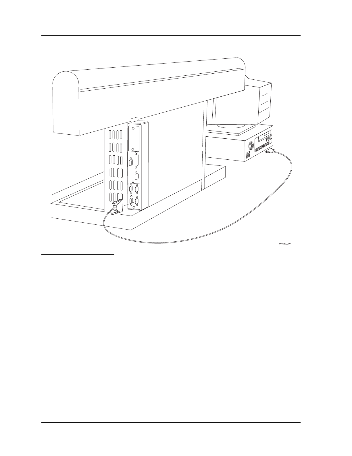
Interconnect Diagrams
The following diagrams show the interconnection of the Biomek Workstation with the
PC controller, and other additional options. Refer to the Biomek 2000 Hardware and
Software Installation Manual for complete installation instructions, or contact your
local Beckman Field Service Engineer.
Biomek 2000 1-5
Page 20
User’s Guide Chapter 1
Document 609909-AA
Figure 2: Connecting the Biomek
Workstation to the Computer
1-6 Biomek 2000
Page 21

Chapter 1 User’s Guide
Document 609909-AA
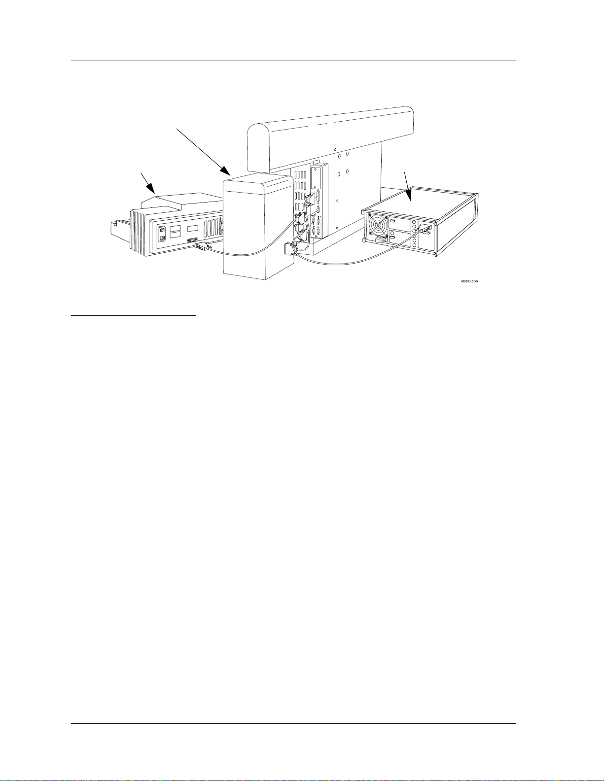
Figure 3: Connecting the Biomek
Workstation to the Side Loader
Controller
Biomek 2000 1-7
Page 22
User’s Guide Chapter 1
Document 609909-AA
Wash Unit
HCB
Plate Reader
Controller
Figure 4: Connecting the Biomek
Workstation to the Plate Reader,
Wash Unit, and HCB Controller
Safety Features
An emergency STOP switch is located on the front of the worksurface. Use the Stop
switch at the base of the workstation if an emergency stop is required. Pressing this
switch will freeze the workstation (but not the Side Loader).
Click on the Stop button on the BioWorks Run window to stop the instrument if the
stop is not an emergency.
1-8 Biomek 2000
Page 23

Chapter 1 User’s Guide
Document 609909-AA
Stop Button
Figure 5: Emergency Stop Switch
CAUTION
Never attempt to physically restrict the movement of the head and
bridge assembly or to exchange labware, reagents, or tools while the
instrument is operating, as indicated by the amber safety light at the
end of the bridge. Use the Stop switch at the base of the workstation if
an emergency stop is required.
Biomek 2000 1-9
Page 24

User’s Guide Chapter 1
Document 609909-AA
1-10 Biomek 2000
Page 25

Safety Precautions
Safety During Installation
Do not lift the Biomek 2000 by the bridge. Two people are needed to lift the Biomek,
grasping the front rail and the back support.
Do not connect the Biomek to an electrical outlet until it is positioned properly on the
bench.
Electrical Safety
To reduce the risks of electrical shock, this equipment employs a three-wire electrical
cord and plug to connect the equipment to earth ground. To preserve this safety
feature:
User’s Guide
Document 609909-AA
Chapter
Two
2
• Make sure the matching wall outlet receptacle is properly wired and earth
grounded.
• Never use a three- to two-wire plug adapter.
• Never use a two wire extension cord or a non-grounding type multiple outlet
receptacle strip.
• Any servicing of this equipment which requires removal of any covers or panels
can expose parts which involve the risk of electric shock or personal injury. Refer
such servicing to Beckman-trained, qualified personnel.
Do not use any power supply other than the type supplied for the accessory for the
Biomek 2000, as appropriate for the country where it is installed.
Safety Against Risk of Fire
Certain electrical circuits within this equipment are protected by fuses against
over-current conditions. For continued protection against risk of fire, replace fuses
only with the same type and rating specified.
2-1
Page 26

User’s Guide Chapter 2
Document 609909-AA
Chemical and Biological Safety
Normal operation of this equipment sometimes involves the use of reagents which are
toxic, flammable, or biologically harmful. When using such reagents, observe the
following precautions:
• Infectious samples must be handled according to good laboratory procedures and
methods to prevent the spread of disease.
• Observe all cautionary information printed on the original solution containers prior
to their use.
• All waste solutions must be disposed of according to your facility's waste disposal
procedures.
• Liquid transfers may generate aerosols. Operate the Biomek in an
appropriate enclosure and take all necessary precautions when using
pathologic, toxic, or radioactive materials.
• Objects dropped onto plates, accidental tool release, or other accidental collisions
may result in splashing of liquids; therefore take appropriate safety precautions,
such as the use of safety glasses when working with potentially hazardous liquids.
• Use an appropriate containment environment when using hazardous materials.
• Observe the appropriate cautionary procedures, as defined by your safety officer,
when using flammable solvents in or near a powered-up instrument.
• Make sure that the vacuum is attached prior to any method that contains any wash
or aspirate functions.
Moving Parts
The bridge and head assembly may suddenly move. To avoid injury due to moving
parts, you must observe the following:
• Never attempt to exchange labware, reagents, or tools while the instrument is
operating, as indicated by the amber safety light at the end of the bridge. When the
light is on, the workstation is in operation and may move suddenly and rapidly at
any moment. A beep sounds just prior to initial movement to provide additional
warning.
• Never attempt to physically restrict the movement of the head and bridge
assembly. Use the Stop switch at the base of the workstation if an emergency stop
is required. Pressing this switch will freeze the workstation (but not the Side
Loader). Click on the Stop button on the Run window to stop the instrument if the
stop is not an emergency.
• Because the parts of the Biomek move automatically, keep clear of the head
assembly during operation. Also, keep the area around the workstation clear
(including the expansion area) to prevent obstructing the movement of the
instrument.
2-2 Biomek 2000
Page 27

Chapter 2 User’s Guide
Document 609909-AA
• Always check the position of the tools and labware before beginning any stage of
the method, to ensure that their locations on the worksurface match those given on
the window. Also, check that the labware is properly seated on the worksurface
before beginning an operation.
Cleaning
You may clean the spill trays of the Biomek worksurface and the nozzles of the Wash
tools. Please observe the following precautions:
• Be careful when handling the Wash tools as the nozzles are sharp.
• Contact your laboratory safety officer and refer to the guidelines in the section
titled "Chemical and Biological Safety" if you will be cleaning spill trays that may
have been exposed to hazardous solutions.
Maintenance
• Turn the POWER off and UNPLUG the Biomek before changing fuses or
performing any maintenance.
• Do NOT autoclave Pipetting or Wash tools; autoclaving may cause damage to the
internal parts.
• Perform only the maintenance described in this manual and in the Biomek 2000
Maintenance and Troubleshooting Guide. Maintenance other than specified in
these manuals should be performed only by Beckman-trained, qualified personnel.
It is your responsibility to decontaminate components of the Biomek
before requesting service by a Bec kman Field Service Representative
or returning parts to Beckman for repair. Beckman will NOT accept
any items which have not been decontaminated where it is
appropriate to do so. If any parts are returned, they m ust be enclosed
in a sealed plastic bag stating that the contents are safe to handle and
are not contaminated.
• Do not replenish bleach in a sterilization reservoir using the aspirate and bulk
dispense transfers, as the bleach may damage the Wash tool.
Accessory Safety
Follow the appropriate safety instructions for the accessories listed below in addition
to the standard safety precautions for the Biomek 2000.
Biomek 2000 2-3
Page 28

User’s Guide Chapter 2
Document 609909-AA
Side Loader (SL)
Verify that the voltage selector is set for correct voltage by a Beckman Representative
at the time of installation.
• DO NOT touch, change, or otherwise interfere with labware on the worksurface,
stacks, or in the SL hand unless the system instructs you to do so.
• The arm can move suddenly. Stay clear of the arm and hand during operation.
• Keep the area around the SL clear of any obstructions to avoid collisions.
• There is a Stop button at the base of each Stack Area. If an emergency stop is
required, pressing this on each stack area of your SL button will freeze the SL
instantly.
CAUTION
The Stop button on the SL will not stop the workstation,
nor will the Stop button on the workstation stop the SL.
NOTE
You may lose data and be forced to quit the run in progress if you
press the SL Stop button. Click on the Stop button on the Run window to stop the instrument if it is not an emergency. Use of the SL
stop button may result in spillage or splattering of liquids in transit.
SL Incubator
• Operating the incubator at 4° C for longer than twenty-four hours may result in ice
formation within the chamber, adversely affecting temperature equilibrium and
assay results.
• Do NOT place the incubator in stack location "C" as the incubator may inhibit
access to the Stop button of the SL in the event of an emergency.
• Allow enough time for the incubator to reach the desired temperature to ensure
reliable assay results (typically less than one hour, depending on the circulator and
desired temperature).
• Use 50% polyethylene glycol and 50% water as the conductive fluid in the water
circulator.
• Maximum inlet pressure to the SL Incubator is 5 psig (34.5 kPa).
• When cleaning the incubator wear protective gloves and eyewear.
2-4 Biomek 2000
Page 29

Chapter 2 User’s Guide
Document 609909-AA
High-Density Replicating System
• The High-Density Replicating System (HDR System) is not autoclaveable, nor
should you use organic solvents to clean the system. However , you can autoclave
the pins of the HDR Tool and use organic solvents to clean the pins.
• If you are using the bleach tray within the tool holder, remove the HDR Tool from
the bleach tray and rinse thoroughly after each session. Do NOT store or let the
HDR Tool stand in the tool holder with its pins immersed in bleach when not in
use. Extended contact with bleach will result in corrosion of the metal pins.
Plate Reader
• Never touch any of the fiber optic cables or their housing, manifold, or rotor
connections. These fibers are extremely delicate and critical to the performance of
the Plate Reader.
• Use only the tools described to perform the steps defined in the Plate Reader user's
manual.
• Do not touch or loosen any screws or parts other than those specifically designated
in the instructions of the Plate Reader user's manual. Doing so could cause
misalignment and possibly void warranty.
• Never perform any operation on the Plate Reader in an environment where
damaging liquids or potentially damaging gases are present.
• Never touch the surfaces of the interference filters or optical lenses.
• DO NOT install the Plate Reader in a stack location that could inhibit access to the
Stop Button of the SL in the event of an emergency.
To prevent fluid from dripping off the microplate when it is in the reading chamber
onto any sensitive optical elements, and to minimize potential biohazard exposure to
other Plate Reader users, observe the following precautions:
• When reading microplates that may have fluid on the underside of the microplate,
damp-dry the underside using a dry paper towel (or equivalent) before putting the
microplate on the drawer. Alternatively, place a clear sheet (such as a Molecular
Devices blanking template) underneath the microplate when inserting it in the
drawer.
• When reading filter bottom microplates where fluid may drip off the filter
membrane, place a clear sheet under the microplate (such as a Molecular Devices
blanking template) when inserting it in the drawer.
Biomek 2000 2-5
Page 30

User’s Guide Chapter 2
Document 609909-AA
Wash System
• Never run the 6-Port Valve dry. Liquid should always run through the 6-Port
Valve. Failure to do so can result in damage to the valve.
• Strong acids, strong bases, oxidizers, radioactive and biohazardous liquids should
not be run through the Wash Unit. Each laboratory must qualify this instrument
with its unique application(s).
• Plug any unused port with the plugs provided with the 6-Port valve. Otherwise
liquid may spill through exposed ports when the 6-Port valve is used.
• When using a Wash tool, make sure a quarter reservoir is installed properly in the
support block under the tool.
Heater-Cooler Block
• Failure to provide cooling water to the heater/cooler block will cause excessive
and potentially dangerous heating of the assembly . DO NOT operate the assembly
without adequate water flow (1 to 2 liters/minute).
• Full power time-out faults may be caused by loss of cooling water. Should this
occur, the heater/cooler unit assembly may be hot.
• Always be sure to shut down the HCB as the last command of each
heating/cooling sequence. Include a shut down command in all Biomek routines.
Provided water cooling is maintained, extended cooling operations do not
adversely affect block life span. The TEMP command may not permanently turn
off the block if a programmed event list is executing.
Biomek 2000 Safety Features
• The Biomek 2000 workstation is equipped with several safety features. A Stop
button is located on the front of the instrument. Press this button to stop the
Biomek. Also, the warning light at the top of the bridge warns you that the
instrument is operating, and emits a beep before the initial movement in a method.
When this light is on, do NOT attempt to change labware.
2-6 Biomek 2000
Page 31

Chapter 3 User’s Guide
Document 609909-AA
Chapter
Three
Principles of
3
Operation
General Information
The following sections are intended to provide an overview of the operation of the
Biomek W orkstation. They are not meant as a comprehensive reference of features and
functionality , but rather as an introductory reference to help you become familiar with
the operational principles. For complete information on each of the software features,
refer to the BioWorks Software Reference Manual.
Note: When running Biomek methods, do not import or export methods or perform other CPU-intensive operations, as communication
between the controller and Biomek workstation may be interrupted.
Note: Beckman does not support the use of network drives to import
and export Lab Books and methods when using BioWorks software.
Lab books should be deleted using the Lab Book Manager only.
The Edit Module
The Biomek uses methods to define the actions that the workstation performs. These
methods are created using the Edit module, within the BioWorks program group.
Biomek 2000 3-1
Page 32

User’s Guide Chapter 3
Document 609909-AA
When you click on the Edit icon, the Edit window is displayed.
Refer to your BioWorks Software Reference Manual for a complete description of all
of the features of the Edit window.
3-2 Biomek 2000
Page 33

Chapter 3 User’s Guide
Document 609909-AA
You can select one of the methods provided with the software by selecting Method
from the menu bar, then selecting Open. The following screen will be displayed.
Select one of the methods (such as the Demo method shown below) from the list
provided in the window, by clicking on that method. Click Open when done.
Once you have selected the Demo method, you will be presented with the dialog
shown on the following page.
Biomek 2000 3-3
Page 34

User’s Guide Chapter 3
Document 609909-AA
Method
List of Actions
Function Palette/
Labware Bar
Setup
Biomek 2000 Worksurface
Button
Creating a Method
When you create a method, you specify the actions that the workstation will perform
using the Edit module. You use the function buttons on the Function Palette to specify
a function (such as a pipetting operation or a labware move). Then you usually click
the labware the function will act upon. In the case of pipetting functions, you specify
the labware where the sample is aspirated, then you specify the labware where you
want to dispense it. In the case of labware moves, you click on the item you want to
move (at its current location), then you click on the location to which you want to
move it.
3-4 Biomek 2000
Page 35

Chapter 3 User’s Guide
Document 609909-AA
When you specify a function in this manner, you are usually presented with a dialog
which you then use to define the specifics of the operation. For example, if you are
defining a pipetting operation, you will indicate the volume to be pipetted in the
dialog.
Setup, Initial Configuration, and Default Configuration
Setup
The Setup function is used to identify (to the software and the Biomek) which
accessories, components, and options are available on the system for a given method.
Refer to the screen shown on page 3-4; the Setup button is shown, located on the
Biomek 2000 worksurface. By clicking on the Setup button, you will be prompted by
the Setup screen, which allows you to change the setup of the system. You will use
setup whenever you want to install (or remove) a wash unit, six port valve, Side
Loader, Disposal units, or a Plate Reader.
Note
The Setup button allows you to change the configuration for a spe-
cific method. If you want to make a more global change to all of the
methods in a lab book, use the Install program, available from the
BioWorks Program Group.
Biomek 2000 3-5
Page 36

User’s Guide Chapter 3
Document 609909-AA
As an example, you may add a Plate Reader to your system, or you may want to move
it from a location on the left side of the worksurface, to a position on the Side Loader .
This is done through Setup. You may also want to take the Side Loader out of the
setup for a particular method because it is not being used for that particular run. You
can disable the Side Loader through Setup, which will allow you more flexibility to
place devices on the SL-accessible locations of the worksurface.
Initial Configuration
The Initial Configuration is the layout of the worksurface at the beginning of an assay.
The initial configuration does not include any transfers, only the locations of the
labware and devices.
The first line of any method is always “Initial Configuration”. When you highlight
this line in the method window, the starting layout of the labware is shown on the
worksurface window.
Initial
Configuratiom
3-6 Biomek 2000
Page 37

Chapter 3 User’s Guide
Document 609909-AA
The workstation setup can only be changed when you are in the Initial Configuration
of the method (that is, you have highlighted the Initial Configuration line). If you
change the workstation setup at any other time, the system will assume that it is a
manual or automatic move and add the step to the method.
Default Configuration
If you are using the same initial layout for multiple methods, you can edit the Default
Configuration to reflect the common items. This way , when you create a new method,
much of the initial configuration layout will already be done for you.
To edit the Default Configuration, select Options/Default Configuration from the
Edit module:
Default
Configuratiom
Worksurface
The worksurface is then displayed. Place the items that you want to appear in the
Default Configuration on the worksurface just as you would for a method.
Biomek 2000 3-7
Page 38

User’s Guide Chapter 3
Document 609909-AA
To save this configuration as the Default Configuration, go to the Method menu and
choose Save As. Verify that the method name is specified as
name must be typed exactly as shown for BioWorks to recognize this as a default
configuration.
Click OK to save the configuration.
Default Config
. The
When you open a new method, you will be given the option of using Default
Configuration as the starting point for the Initial Configuration.
Placing Labware on the Worksurface
You place labware on the worksurface for use by a method as follows:
Select the piece of labware (plate, tube rack, device, etc.) from the Labware bar. Use
the buttons at the far right to select a labware category , and use the scroll box to select
a specific labware type within that category.
Specifying a Method Step (Action)
First, click the desired function icon on the Function palette. In this example, the Mix
at Location icon is selected.
Mix at
Location
Icon
3-8 Biomek 2000
Page 39

Chapter 3 User’s Guide
Document 609909-AA
Then, on the worksurface, click on the labware where the Mix at Location action
should take place.. In this example, the 96-well flat plate in location B2 is selected.
The following Mix at Location dialog will appear.
Once you have defined all actions and tip handling options in the screen, click OK
when done.
Biomek 2000 3-9
Page 40

User’s Guide Chapter 3
Document 609909-AA
The resulting method steps will appear in the Method List of Actions, as demonstrated
below:
Method List of Actions
Error Messages During Labware Placement
When you are placing labware on the worksurface, you may see a number of different
types of messages, regarding the restrictions on placement of certain items. These
range from informational warnings about possible interference (which you may
choose to ignore, based on your knowledge of the method) to warnings which forbid
you from placing labware at certain locations.
Pipette Transfers
The most commonly used function of the Biomek is the pipette transfer. Most pipette
transfers define the transfer of a specific volume of liquid from one place on the
worksurface to another.
3-10 Biomek 2000
Page 41

Chapter 3 User’s Guide
Document 609909-AA
The Pipette Transfer icon button is shown below and is found on the Function Palette:
Pipette Transfer Icon
When you have placed labware, tools, and tips on the worksurface, you can then
specify a pipette transfer to move liquid from one plate to another. To do this, click the
Pipette Transfer button on the Function Palette, click the Source plate on the
worksurface, then click the Destination plate.
The Pipette Transfer window, shown below, is used to define the transfer.
Biomek 2000 3-11
Page 42

User’s Guide Chapter 3
Document 609909-AA
Information pertaining to the source labware (used for aspiration) is on the left of the
screen, and information pertaining to the destination labware (or destination) is on the
right. Transfer volume, tool and tip options are located in the center of the screen. The
fields that you will edit on this screen are summarized below:
Source
Aspirate Height sets the height the tip goes into the labware. The range is from
-10% to 110%, where 0% is at the bottom of the labware well and 100% is at the top.
Some tool and tip combinations cannot go all the way to the bottom of certain types of
labware, in which case the range will be limited by BioWorks.
Liquid Level options are Fixed, Liquid Level Sensing, or Liquid-Level Tracking.
• Fixed means that on each visit to the source labware, the tip will go to the
programmed aspirate height.
• Sensing will determine where the liquid is in a well, then aspirate the volume just
below the surface (miniscus). Sensing is only available with the P200L and
P1000L tools. These tools sense the liquid level and automatically determine the
aspirate height.
Sensing is used on each visit to a well when a new tip is used, and on the first visit
to the well if the same tip is used. Subsequent visits use tracking to calculate the
proper depth. When Sensing is selected, the Tip Depth box becomes active. Use
this to set an aspirate depth below the depth calculated for the aspiration volume.
Enter the number of millimeters below the liquid level at which you wish to use
the Biomek to aspirate in the Depth field. This may be useful to aspirate the lower
level of a two-phase solution.
Sensing also detects whether or not a tip is present, and will also reject “dirty” tips.
Always use clean tips with liquid sensing.
Hint
You should usually use a tip depth of 5mm to 10mm to ensure that
only liquid is aspirated from the well. A setting of 0mm can cause
problems due to aspiration of air.
• Tracking means that on the first visit to the well, the tip goes to the programmed
height. On subsequent visits, the system will calculate the distance to move down
based on the volume of liquid it aspirated on the previous visit, and the shape of
the labware. This feature is useful if a full tube is to be emptied with multiple
aspirations, because no liquid will remain on the tip, and the liquid will not be
spilled out on the first visit.
Hint
Set the first height well below the actual level to ensure that all liquid
is aspirated, and to avoid aspiration of air.
3-12 Biomek 2000
Page 43

Chapter 3 User’s Guide
Document 609909-AA
Aspirate Rate can be set from 1 to 10. Note that the scale is logarithmic, with lower
numbers being slower. A setting of 6 is quite slow.
Prewet causes the system to pipette extra liquid into and out of the pipette tip before
aspirating the specified volume. This can reduce surface tension between the liquid
and the pipette tip. The actual volume used for prewetting is programmed in the Tool
Edit window.
Tip Touch is used to remove liquid from the outside of the tip after the aspiration by
touching the tip to the side of the well. Tip touch is done at a height which is preset for
each individual type of labware.
Mix settings are on a pop up window which appears when you click Mix V alues. The
mix feature aspirates and dispenses for a specified number of times (cycles) to mix
solutions. Selecting Mix allows you to specify a mix routine function in either the
source or destination range. The Mix occurs prior to aspiration. For many liquids, you
should aspirate from the bottom of the well and dispense near to the top at a rate of 10
to optimize mixing.
Ranges and Patterns are used to set the wells that the tool will visit in the source
labware.
• Range is a contiguous set of wells. You specify the sequence of wells with a
direction of “by Row,” “by Column,” “Box by Row,” or “Box by Column.”
• Pattern is a non-contiguous set of wells. Patterns can be stored and recalled when
needed.
End Action describes what the workstation should do when it has finished with the
first piece of labware. End Action is one of the following:
• Stop stops the transfer after the source range has been completed.
• Repeat Same Labware repeats the source range until the destination range has been
filled. Repeat Same Labware can be used at both the source and the destination.
• Repeat Next Labware completes the range at the source then waits for the next
piece of labware on the worksurface at the same location. (This does not mean that
the source range is repeated at the labware next to the original source.) Move the
next piece of labware into position using either a manual move or an automatic
move (with a Set Shelf command) if a Side Loader is present.
Marks are used to tell the system where the last transfer finished in the range so that
the system can resume the range on subsequent transfers and not return to the
beginning of the range. You can use the following options for setting marks:
• Use no Marks is the default setting.
• Set a New Mark marks the well where the next pipetting function at that piece of
labware is to begin.
• Use an Existing Mark starts the system at the current mark. This does not move the
mark after the transfer is complete.
• Use then Set New Mark starts the system at the current mark and moves the mark
after the transfer.
Biomek 2000 3-13
Page 44

User’s Guide Chapter 3
Document 609909-AA
Marks are invisible to the user. Marks stay with the labware, no matter where the
labware is moved. This is particularly useful when a Side Loader or Gripper Tool is
used to move labware on the worksurface. Marks cannot be used with a serial transfer .
Destination
Most functions at the destination are similar to the corresponding source functions. By
default, there are three different tool types (categories) for each pipetting tool: contain,
deliver and repeat.
Note:
Make sure the tool type matches the delivery type selected at the desti-
nation. Each tool type has been optimized for a specific delivery type.
The differences are noted below:
Delivery Ty pe can be selected as one of the following:
• To Contain causes the tip to pick up the requested volume and dispense that
volume. This is usually used in conjunction with the “blowout” setting to ensure
that all of the liquid is expelled from the tip. Please note that the tool name
"contain" is not used in the Bioworks database.
• To Deliver causes the tool to pick up the requested volume plus an additional
overage amount which is programmed into the Tool Edit screen (described later).
Only the requested volume is dispensed, therefore liquid will remain in the tip, and
will be discarded with the tip. To deliver cannot be used with “blowout.”
For many liquids, the combination of To Contain and Blowout provide the most
accurate delivery.
Another related option, Repeat Pipette, is controlled from the Advanced screen,
discussed later.
Replicates are used to dispense to multiple wells from a single source well (or set of
wells for multi-tip tools). Replicates are entered using the “spin box.” The highlighted
wells on the range are linked by a line indicating the replicates chosen. The replicate
number must be divisible into the total range selected.
For single tip tools, the replicate number is linked to repeat pipetting (discussed later).
The direction of the pipetting action selected will influence the direction of the
replicates.
Marks are handled the same at the destination, as at the source. All marks can be
cleared using the Clear Marks icon on the function palette, as shown on the next page.
3-14 Biomek 2000
Page 45

Chapter 3 User’s Guide
Document 609909-AA
Tool Options
Tool
shows the default tool selected by the system based on the tools available in the
initial configuration and the labware in use. For example, a multi-tip tool will not be
used by default if a 24 tube rack is used as the source. If multiple compatible tools are
available, then the first compatible tool in the tool list (alphabetically) is the default.
Hint
To select a specific tool before calling up the pipetting screen, click on
the tool in the tool rack before clicking on the source and destination.
This tool will then be used for the default.
By default, there are two specified tool types for each of the pipetting tool: deliver, and
repeat. Make sure the tool type matches the delivery type selected at the destination.
Each tool type has been optimized for a specific delivery type.
Volume is the volume of liquid to be transferred.
Tip Handling Options
Tip Change can be one of the following:
• No tip change uses the same tips for all transfers
• After Transfer changes the tip after each transfer
• At End of Row/Column changes the tip when the end of the a row or column is
reached, whichever comes first. For a multi tip tool, this is identical to “After
Transfer”
• At New Replicate changes the tip before a new replicate
Discard Tips releases the tips into the Disposal chute after use. Otherwise, tips are
returned to the tip rack.
Biomek 2000 3-15
Page 46

User’s Guide Chapter 3
Document 609909-AA
Tip Source allows you to select the label of a tip rack to use. Tip racks are used from
left to right, and from an A row to a B row by default. To change this order, label the
tip rack when setting up the worksurface (by double clicking on the tip rack) then
select the tip rack from the list in the Pipette Transfer window.
Advanced Options
Note: Validation of new labware is based upon the labware Type, and
corresponding dimensions.
To display the Advanced options, click the Advanced button near the bottom, center
of the Pipette Transfer dialog.
3-16 Biomek 2000
Page 47

Chapter 3 User’s Guide
Document 609909-AA
The following Advanced screen contains the options for delays and repeat pipetting.
To return to the Basic options, click on the Basic button near the bottom of the
screen.
Repeat Pipetting is a single pick-up, multi-dispense mode of pipetting. The volume
entered is the volume of each delivery, not the total volume to be delivered. For
single-tip tools, the repeat count may be less than or equal to the replicate number but
can be no greater than the replicate number. Also, the number used for Repeat Count
multiplied by the volume per tip must be less than or equal to the capacity of the tool.
Internal Delay is for delivering liquid at exactly the same time interval from one
destination to the next. The internal delay will not take affect until the second transfer.
The system will wait above the destination and then deliver when the internal delay
time is reached. The clock starts at the delivery of the first sample. This first transfer
establishes the base time to which all subsequent delays are compared and all
subsequent transfers are to begin on the beat. For example, if the biomek arrives at the
start of a transfer early , it waits for the next beat, which is balance of of the delay from
the start of the last transfer. If the biomek is late (i.e., because it changed tips) it
executes the transfer immediately . If it is still late, it executes transfers until it catches
up with the beat.
Biomek 2000 3-17
Page 48

User’s Guide Chapter 3
Document 609909-AA
Printing Methods
A method must be saved in order for the latest changes to be printed.
Mix and Serial Transfer Pipetting Functions
These specialized pipetting functions are also available from the function palette.
These are described below.
Mix
The Mix icon button is shown below:
A mix within a single well or at a single piece of labware can be programmed
independently of a transfer using this function. The following dialog appears when the
Mix icon and a piece of labware are clicked.
3-18 Biomek 2000
Page 49

Chapter 3 User’s Guide
Document 609909-AA
Serial Transfer
The Serial Transfer icon button is shown below:
Serial transfers occur only within one piece of labware. The same volume is
transferred between successive wells in the highlighted range. If a mix is programmed
on the serial transfer screen, the mix occurs after the transfer of the liquid. This means
that when the system visits the first well in the range, no mix takes place at that well.
A Serial Transfer is defined using the Serial Transfer dialog:
Biomek 2000 3-19
Page 50

User’s Guide Chapter 3
Document 609909-AA
Tip Handling Functions
The following tip handling functions are also available from the function palette.
Tip Change
The Tip Change icon button is shown below:
A tip change can be programmed between functions rather than included within a
pipetting function. This allows you to specify a tip change function between two
consecutive functions that do not include a tip change.
If the second function has a tip change programmed within it and the first does not,
then the system will automatically change tips between the two functions. The logic
behind this is that if the second function requires clean tips for each transfer within it,
then it should start with clean tips.
Reset Tip Rack
The Reset Tip Rack icon button is shown below:
This is used to set the tip rack to a given tip. You can select the first tip to be used
anywhere in a rack. This allows you to optimize tip usage.
You use the Reset Tip Rack dialog to indicate how many tips in the rack have been
used. Tips are numbered starting with tip #1 as the tip in the upper left-hand corner , tip
#2 immediately below it in the same column, and so on. Setting this value to zero
causes the system to use all of the tips in the rack as new.
3-20 Biomek 2000
Page 51

Chapter 3 User’s Guide
Document 609909-AA
Wash Tool Functions
There are four icons related to Wash Tool functions. These icons are only active if the
Wash Unit has been selected through Setup in the Initial Configuration (see pg. 3-5).
Wash
The Wash icon button is shown below:
The Wash function allows you to wash a plate using either the Wash 1 or the Wash 8
tool. If the Six Port Valve option is installed, then a specific buffer can also be selected
for the wash operation.
Many of the operations controlled from the Wash dialog are similar to the Pipette
Transfer dialog. Those that are not are described below.
Source Reagent
Wash Cycles
Delay
Wash at Sides
Internal Delay
washes of consecutive wells.
Aspirate Duration
Aspirate Height
the values refer to the height of the longer aspirate needle on the tool.
controls the time between wash cycles.
specifies a reagent or buffer if the Six-Port Valve is insta lled.
controls the number of aspirate and dispense cycles per well visit.
is only available for flat-bottom labware.
is the same as for pipetting. It provides a consistent time between
controls the time the vacuum valve is opened.
and
Dispense Height
are the same as for pipetting, except that
Aspirate
The Aspirate icon button is shown below:
The Aspirate function uses the wash tools to remove liquid from a plate or tubes using
the vacuum source.
Duration
the source. (The Aspirate function is based on time, not on volume.)
Biomek 2000 3-21
controls the length of time that the valve is open and liquid is removed from
Page 52

User’s Guide Chapter 3
Document 609909-AA
All of the other parameters are the same as for pipetting and wash operations.
Bulk Dispense
The Bulk Dispense icon button is shown below:
Bulk dispense uses the wash tool to dispense liquid to a plate or a tube. The volume
dispensed in a bulk dispense operation is not as accurate as with a pipette transfer , b ut
it is quicker because the tool does not have to visit the source labware.
Aspirate Excess turns on the vacuum briefly to bring all of the liquid in the wells to
the same height.
All of the other parameters for a bulk dispense operation are similar to those for wash
and pipette functions.
Purge
The Purge icon button is shown below:
Purge is used particularly in conjunction with the Six Port Valve when changing
buffers. In this situation it is necessary to remove the previous buffer from the lines
before starting to use a new buffer. To use this function, click the Purge icon in the
Function Palette, then click the tool in the Tool Rack to be purged.
Source Reagent indicates which buffer the tool is to be purged with.
Purge Volume controls the volume of buffer to purge with.
Purge Rate sets the rate of the peristaltic pump.
3-22 Biomek 2000
Page 53

Chapter 3 User’s Guide
Document 609909-AA
Labware Moves
The Move icon button is shown below:
All labware moves in a method, whether manual or automatic, are controlled by the
Move icon on the Function Palette. If a Side Loader or Gripper Tool is present, then
the system assumes an automatic move, if the labware and locations are compatible.
Manual Moves
This section describes manual moves, which require an operator intervention to move,
remove, or replace labware. Automatic Moves are covered in the next section.
To add a manual move to a method, click on the Move icon then click the piece of
labware to be moved. Then click the destination for the labware. If you want to
remove a piece of labware from the worksurface, use the Remove icon on the
labware bar (in the “Other” group) to perform this function.
Automatic Moves
When a Gripper T ool is present on the system, you can move most labware items from
one location on the worksurface to another location, or to the Disposal unit. In
addition, you can also use the Gripper Tool to remove lids from plates and tip racks,
and to stack labware on devices such as the Vacuum Manifold.
When a Side Loader is present, you can move labware and tip racks between shelves
on the Side Loader stack area and the worksurface. You can also use the Side Loader
to remove lids, and to dispose of used labware and lids into the SL Disposal unit.
All of these functions are added to a method through the Move icon. First you click the
Move icon, then click the labware to be moved, then click the destination. If you
selected a piece of labware which currently has a lid, you will be prompted to select
whether you want to move only the lid or to move the lid and labware. Other prompts
may also appear to allow you to further specify exactly what you want to move.
Both the Gripper Tool and the Side Loader are also capable of moving plates to and
from the optional Plate Reader when it is installed in a compatible location.
Biomek 2000 3-23
Page 54

User’s Guide Chapter 3
Document 609909-AA
Editing Existing Methods
One of the simplest ways to write a method is to copy an existing one, then change it
to suit your needs. The following guidelines apply to editing methods:
• Open the method you want to edit and then use the
to save a copy of it under another name. This keeps the original method intact.
• When adding a step to a method, use the highlight line (in the method edit
window) to select the step which will follow your new step(s). When you add a
step to a method, it is always added above the line which is highlighted.
• If you want to change the setup of the method, you must highlight the Initial
Configuration line of the method. Be aware, however, that changing the labware
arrangement in the Initial Configuration of an existing method may cause transfer
functions, which occur later in the method, to become invalid.
Method/Save As
command
Saving Methods
When you are ready to save your new method, select the
from the menu bar in the Edit window. You can enter a different name for the method,
if you wish, or use the current one.
Method/Save
command
You will also notice a check box at the bottom of the Save dialog labeled
Unvalidated
that there are no conflicts with tools, labware, or other problems. When this box is
unchecked (the default) the Biomek automatically validates each method when it is
saved.
If you are making an interim save (that is, the method is not yet complete but you want
to save what you have so far) you should check this box so that the system does not
attempt to validate the method.
3-24 Biomek 2000
. Validation is a system of internal checks done on a method to ensure
Save
Page 55

Chapter 3 User’s Guide
Document 609909-AA
If validation fails, the method is not saved and a message is displayed to explain the
source of the failure. You must correct the problem before you will be able to validate
the method.
Note that you must successfully validate a method before it can be run.
Running a Method
The Run icon button is shown below. This icon is found on the icon bar at the top of
the BioWorks Edit window.
Once you have saved your method and validated it, you can run it using the Run
module. If you are in the Edit module, you can simply click the Run icon button in the
toolbar to bring up the Run dialog and begin running the method.
Note: After the method is run, a ".txt" file will be created in the rootBioWorks directory.
You can set the characteristics of the Run module using the
menu bar in the Run module. These options are as follows:
Options
menu from the
Alarms and Suppress All Alarms
Various alarm levels can be set so that the system will warn the operator only during
certain conditions. When one of the following options is checked in the menu, the
alarm is enabled for that type of error condition:
System Fatal
as a collision).
Method Fatal
detected.
Method Halt
intervenes (to provide more tips, for example).
Method Pause
intervention.
Warnings
the method continues.
alarms when an error occurs that causes the system to shut down (such
alarms when the method must be aborted, such as when a stall is
alarms when the method has stopped but can be restarted after a user
alarms when the method has paused for a programmed user
alarms when a warning message is posted. No intervention is required and
Select the
Biomek 2000 3-25
Suppress All Alarms
option if you want to disable all of the alarms.
Page 56

User’s Guide Chapter 3
Document 609909-AA
Verify Configuration
When this option is enabled, the user will be prompted to verify the setup of the
labware and tools on the worksurface when a run begins. (A view of the worksurface
is displayed when the Start button is clicked to begin a run.)
Save Preferences
All the settings for the above options can be saved so that they are used for each
method run by selecting this option.
Dry Run
This turns off the Tool Type identification and liquid level sensing for the run. This
allows you to test the method run without reagents.
Stop and Quit Functions
You can stop (pause) or quit a method from the run display.
Stop stops the method at the point the button is clicked. The method can be continued
using the Continue button, or stopped using the Quit button.
Trace is used to move the Biomek one motion at a time after Stop has been activated.
Go Up moves the pod directly up after Stop has been activated.
Cancel Loop cancels a loop after Stop has been activated. The loop is cancelled once
the current iteration completes.
Quit aborts the method immediately.
Functional Verification and Self Diagnostics
The power-up software performs the following diagnostic checks:
• confirms connection of the cable between the workstation and the computer
• verification of the checksum for the EPROM
• performs a check of the ROM
• checks the first 1 MB of RAM
If an error is detected, an error code is displayed through the diagnostic LEDs located
on the workstation. Contact an authorized Beckman service engineer for additional
information if a power-up error is detected.
3-26 Biomek 2000
Page 57

Chapter 3 User’s Guide
Document 609909-AA
Performance Characteristics and Specifications
Performance characteristics for the pipette tools are shown below:
Tool Pipetting Precision
P20 5% C.V. at 1µL
MP20 5% C.V. at 1µL
P200L 5% C.V. at 5µL
MP200 5% C.V. at 5µL
P1000L 2% C.V. at 50µL
Wash1 15% C.V. at 50µL
Wash8 15% C.V. at 50µL
Biomek 2000 3-27
Page 58

User’s Guide Chapter 3
Document 609909-AA
3-28 Biomek 2000
Page 59

Chapter 4 User’s Guide
Document 609909-AA
Chapter
Four
Basic Operating
4
Procedures
Basic Operating Procedures
Note
This manual does not attempt to address all of the functionality avail-
able with the BioWorks operating software for the Biomek 2000.
Rather, this section provides a number of tutorial examples designed
to illustrate the most important and commonly used features of the
system.
For complete information on BioWorks features and functions, refer
to the BioWorks Software Reference Manual.
Editing the BioWorks Demo Method
This section will guide you through the basics of editing by changing an initial
configuration and a transfer function using the Demo method.
T o begin, double click on the
the Edit window, as shown on the next page.
icon in the BioWorks program group. This displays
Edit
Biomek 2000 4-1
Page 60

User’s Guide Chapter 4
Document 609909-AA
The name of the current lab book is shown in angle brackets at the top of the window.
If the BOOK1 lab book is currently the default, skip to the next step in the middle of
page 4-4. Otherwise change the lab book to BOOK1, by selecting Options/Select
Lab Book... from the Menu bar.
4-2 Biomek 2000
Page 61

Chapter 4 User’s Guide
Document 609909-AA
Select Lab Book
Biomek 2000 4-3
Page 62

User’s Guide Chapter 4
Document 609909-AA
This displays the Select Lab Book dialog:
Highlight the BOOK1 lab book, then click on the Select button.
When the Edit window displays <BOOK1> as the current lab book, select
Method/Open from the Menu Bar of the Edit window. This will display a list of
available methods. Select the Demo method from the list, then click Open.
4-4 Biomek 2000
Page 63

Chapter 4 User’s Guide
Document 609909-AA
Biomek 2000 4-5
Page 64

User’s Guide Chapter 4
Document 609909-AA
BioWorks loads the method, then displays the Method, Function Palette, and
Worksurface windows, as shown below.
Before we begin editing the method, let’s review some important features of the Edit
window and its "child" windows:
• Make sure that the “Initial Configuration” line in the Method window is
highlighted before you begin placing or moving labware on the worksurface. The
labware and locations set when the “Initial Configuration” line is highlighted will
be used as the starting point. BioWorks prompts you to verify that labware is
arranged properly when you start a method.
• To place labware on a worksurface location, first you select the item from the
Function Palette/Labware Bar window. Use the round buttons to select the type of
labware, then scroll to select a specific item. Then place the labware on the desired
location on the Worksurface window.
• To delete an item of labware from the Worksurface, click on the item, then press
the Delete key. (You will be prompted for confirmation.)
4-6 Biomek 2000
Page 65

Chapter 4 User’s Guide
Document 609909-AA
• When adding or placing labware on the worksurface, you may receive a “Possible
Collision” error message. If this occurs, this does not necessarily mean that you
cannot use that position for that labware. However, you should carefully consider
whether or not the adjacent labware will cause a conflict based on the information
in the warning message. If in doubt, consider using another arrangement.
• If you add, delete, or remove labware when any other line of the method is
highlighted, BioWorks will consider this a labware move, and will function
accordingly.
• If you add, delete, or move labware during a method, you will notice that the
labware displayed on the Worksurface window changes as you increment through
the steps in the Method window . This will allow you to verify labware positions as
the method progresses.
Changing the Initial Configuration
To change the Initial Configuration for this method, first make sure that the Initial
Configuration line of the Method is highlighted.
Then, click on the Plates button of the Labware bar, then scroll through the list and
select the 96-well flat bottom plate.
The cursor becomes a rectangle (to represent the plate). Place the rectangle on position
B4 to add a third plate to the initial configuration. The new configuration, with the
96-well plate located in position B4 of the worksurface, is shown on the following
screen.
Biomek 2000 4-7
Page 66

User’s Guide Chapter 4
Document 609909-AA
Viewing and Editing a Transfer Function
Familiarize yourself with a basic Pipette Transfer function by viewing the first transfer
function in the Demo Method. To do this, double-click on the second line in the
Method window. This displays the Pipette Transfer dialog for this step.
4-8 Biomek 2000
Page 67

Chapter 4 User’s Guide
Document 609909-AA
In this function, the Biomek pipettes 200µL from location A2 to B2 on the
worksurface, using the P200L tool. When you have finished viewing the
configuration, click Cancel to exit the dialog without making any changes.
Next, we will modify the configuration of the second transfer function.
Biomek 2000 4-9
Page 68

User’s Guide Chapter 4
Document 609909-AA
Double-click on the second function (the third line) of the method to display the
Pipette Transfer dialog.
To add a Mix function to this step, click on the Mix option box for the source.
Then click on the Mix Values button to display the Mix Values dialog. Edit the Mix
Values dialog as follows:
• Change the Mix Cycles to 3
• Change the Aspirate and Dispense Rates to 5
• Change the Aspirate and Dispense Heights to 50%
4-10 Biomek 2000
Page 69

Chapter 4 User’s Guide
Document 609909-AA
When you are done, click on OK to exit this dialog, then click on OK again from the
Pipette Transfer window. Note that the Edit Window will not reflect changes made to a
transfer function when they involve parameters not included in the descriptor line.
Adding a Transfer Function
Now you will add a new transfer function to the method. Highlight the last transfer
function in the Method window, then click on the Pipette button on the Function
Palette.
Biomek 2000 4-11
Page 70

User’s Guide Chapter 4
Document 609909-AA
The cursor’s shape changes to a pipette symbol.
Click on location A2 to designate the source, then click on location B4 for the
destination. The Pipette Transfer dialog is displayed.
Set the options on the dialog as follows:
• Make sure the Tool is set to P200L
• Set the volume to 100µµµµl per tip
• Set the Source Labware Action to Range and the Direction to By Row. Use the
cursor to highlight the top row of wells on the source plate
• Set the Destination Labware Action to Pattern and Direction to By Row. Use the
cursor to highlight at least 6 wells of the destination plate in any pattern you
choose.
Note that if you select more than 6 wells, only the first six will be used because
there are only 6 source wells selected. If you want to fill more than 6 wells on the
destination plate, you could either select more source wells (to fill each with a
different source) or change the Source End Action to “Repeat Same Labware”
(which would reuse the source wells until all of the destination wells were filled).
• Select a Tip Touch at the source and at the destination
• Select Fixed for Liquid Level
4-12 Biomek 2000
Page 71

Chapter 4 User’s Guide
Document 609909-AA
The dialog should look like the one shown on the following screen (patterns for the
destination plate may be different).
Click OK to add this step to the method.
Inserting Messages and Pauses
You can also insert messages to the operator and system pauses in a method. Using the
same method, now add a pause before the second pipette transfer to display a message
to the operator. We will display a message to inform the operator that the system will
pause for one minute after the message is acknowledged.
From the Edit Window, highlight the second pipette transfer (in the Method Window)
then click on the Pause System button (shown on the next page), located on the
function pallette.
Biomek 2000 4-13
Page 72

User’s Guide Chapter 4
Document 609909-AA
This displays the System Pause/Message dialog. Select the dialog items as follows:
• Set System Activity to Message
• Set System Actions to Display message until canceled
• Type a message in the Message box
• Enable the Message Alarm and set the Interval, if you wish
The dialog should look like the one shown:
Click OK to add the Message step to the method. (Note that we have not yet added the
pause itself.)
4-14 Biomek 2000
Page 73

Chapter 4 User’s Guide
Document 609909-AA
Now, insert the system pause between the message and the next pipette transfer.
Highlight the second pipette transfer line in the method (note that new method steps
are always inserted before the highlighted line in a method).
Click on the Pause System button again.
This displays the System Pause/Message dialog. Specify a pause by selecting the
dialog items as follows:
• Set System Activity to Pause System
• Set System Actions to Pause system for, then set the timer to 1:00 minute
The dialog should look like the one shown:
Click OK when you are finished.
Biomek 2000 4-15
Page 74

User’s Guide Chapter 4
Document 609909-AA
Saving a Method
Before proceeding, you should save your edited method under a different file name.
To do so, select Method/Save As... then enter a file name of your choice in the
dialog.
Note that when you save a method, it is automatically validated, unless you request
otherwise. A method must be validated before it can be run.
4-16 Biomek 2000
Page 75

Chapter 4 User’s Guide
Document 609909-AA
Running a Method
Before you run a method for the first time on a new Biomek, you must perform an
alignment check and re-align the Biomek (and Side Loader) if necessary. Refer to the
Biomek 2000 Hardware and Software Installation Guide for alignment instructions. If
the Biomek has already been aligned and been in use, you can run your new method
now.
T o run the method, click on the Run icon in the icon bar of the BioWorks Edit window:
The Biomek 2000 Configuration screen will appear. This screen will serve to remind
you to set up labware, tip racks, and tools on the worksurface.You will be prompted to
accept the worksurface configuration. When you have set up your worksurface
appropriately , click on the Accept All button to accept the worksurface configuration.
Biomek 2000 4-17
Page 76

User’s Guide Chapter 4
Document 609909-AA
The method will begin, and the Method Run screen will be displayed, showing a list
of actions performed during the method run.
4-18 Biomek 2000
Page 77

User’s Guide
Document 609909-AA
Chapter
Five
Recommended
5
Maintenance Procedures
Maintenance Procedures
General Information
This section is intended to be a checklist of recommended maintenance and
preventative maintenance procedures.
Note that the intervals indicated are suggestions only , based on typical usage. You may
need to realign or recalibrate more frequently.
Weekly
The following procedures should be performed weekly or more frequently as indicated
by instrument performance.
Perform a Position Calibrate
Use the
perform a calibration on the system.
Perform Check Disk
Use the MS-DOS command
file system and directory structure on the computer's hard disk and possibly free up
some disk space.
Refer to the DOS and Windows manuals, which were provided with your computer,
for more information on file management techniques.
Align/Position Calibrate
chkdsk
command from the Edit module main window to
(“check disk”) with the
option to verify the
/f
Verify the Alignment Points
Use the Diagnostics program to verify each of the alignment points for the equipment
on your system. Do this for the worksurface, the Side Loader Stack Areas, the Plate
Reader, and any other positions which apply to your system.
5-1
Page 78

User’s Guide Chapter 5
Document 609909-AA
If re-alignment is needed, refer to the Biomek 2000 Hardware and Software
Installation Manual for complete instructions.
Check Finger Pads for Wear
If your system includes a Side Loader or a Gripper Tool, then you should periodically
check the pads on the fingers for wear and replace the pads as needed.
For instructions on replacing finger pads for the Side Loader hand and for the Gripper
Tool, refer to the Biomek 2000 Maintenance and Troubleshooting Guide.
Monthly
Once a month (or more often, as required) you should thoroughly clean the
worksurface. Refer to the Biomek 2000 Maintenance and Troubleshooting Guide for
complete instructions.
In addition, you should verify that the following safety features are functioning
properly:
• The Warning light on the Head assembly
• The Warning buzzer on the Head assembly
• Emergency Stop switch on the workstation and on the Side Loader (if applicable)
You can verify the first two by observing the workstation during a method, and noting
whether the light and buzzer come on at the appropriate times (when a method is
started).
To check the Emergency Stop switches, run a method (using either dry labware or
using the “Dry Run” option, as desired) then press the Stop switch and observe
whether or not the method and movement halts.
Note that the Stop switch on the worksurface only stops the pipette head, and the Stop
switch on the Side Loader only stops the Side Loader.
Semi-Annually (Every Six Months)
The following procedure should be performed every six months or more frequently as
indicated by instrument performance.
Calibrate Pipetting Tools
Refer to the Biomek 2000 Maintenance and Troubleshooting Guide for a complete
discussion of tool calibration.
5-2 Biomek 2000
Page 79

User’s Guide
Document 609909-AA
Chapter
Parts, Supplies and Accessories
Diagnostics Overview
General Information
For the most current list of parts, supplies, and accessories, contact your local Sales
Office.
United States Sales Telephone Number
Please use the following address and phone number for all inquiries in the U.S.:
Six
6
Beckman Instruments, Inc.
4300 N. Harbor Blvd.
P.O. Box 3100
Fullerton CA 92834-3100
Sales: 1-800-742-2345
Service: 1-800-551-1150
Fax:1-800-643-4366
World Wide Web
You can also access additional information and find out more about new products for
the Biomek 2000 from:
www.beckmancoulter.com
The BioRobotics User Resources section contains information specific to users of the
Biomek 2000.
6-1
Page 80

User’s Guide Chapter 6
Document 609909-AA
6-2 Biomek 2000
 Loading...