

Page 1
Manual | EN
CX2550-0x79
USB Extension for CX20xx
2/10/2021 | Version: 1.0
Page 2

Page 3

Table of contents
Table of contents
1 Foreword ....................................................................................................................................................5
1.1 Notes on the documentation..............................................................................................................5
1.2 Safety instructions .............................................................................................................................6
1.3 Documentation issue state ................................................................................................................7
2 Product overview.......................................................................................................................................8
2.1 Intended use......................................................................................................................................8
2.2 System overview ...............................................................................................................................9
2.3 CX2550-0179 - Technical data........................................................................................................10
2.4 CX2550-0279 - Technical data........................................................................................................11
3 Mounting and wiring................................................................................................................................12
3.1 Unpacking, installation and transport ..............................................................................................12
3.2 Dimensions......................................................................................................................................13
3.3 Attaching the system interface to the CX20x0 system ....................................................................14
3.4 Installation on the mounting rail.......................................................................................................14
3.5 Mounting the module lock................................................................................................................17
3.6 USB connection...............................................................................................................................19
4 Commissioning / Configuration .............................................................................................................20
4.1 Switching on and off ........................................................................................................................20
5 CX2550-0179 - Architecture description................................................................................................21
6 Error handling and diagnostics..............................................................................................................22
6.1 LEDs Diagon the USB extension.....................................................................................................22
6.2 Faults...............................................................................................................................................23
7 Decommissioning....................................................................................................................................24
7.1 Disassembly and disposal ...............................................................................................................24
8 Appendix ..................................................................................................................................................26
8.1 Certifications....................................................................................................................................26
8.2 Support and Service ........................................................................................................................27
CX2550-0x79 3Version: 1.0
Page 4

Table of contents
CX2550-0x794 Version: 1.0
Page 5

Foreword
1 Foreword
1.1 Notes on the documentation
This description is only intended for the use of trained specialists in control and automation engineering who
are familiar with applicable national standards.
It is essential that the documentation and the following notes and explanations are followed when installing
and commissioning the components.
It is the duty of the technical personnel to use the documentation published at the respective time of each
installation and commissioning.
The responsible staff must ensure that the application or use of the products described satisfy all the
requirements for safety, including all the relevant laws, regulations, guidelines and standards.
Disclaimer
The documentation has been prepared with care. The products described are, however, constantly under
development.
We reserve the right to revise and change the documentation at any time and without prior announcement.
No claims for the modification of products that have already been supplied may be made on the basis of the
data, diagrams and descriptions in this documentation.
Trademarks
Beckhoff®, TwinCAT®, EtherCAT®, EtherCAT G®, EtherCAT G10®, EtherCAT P®, Safety over EtherCAT®,
TwinSAFE®, XFC®, XTS® and XPlanar® are registered trademarks of and licensed by Beckhoff Automation
GmbH.
Other designations used in this publication may be trademarks whose use by third parties for their own
purposes could violate the rights of the owners.
Patent Pending
The EtherCAT Technology is covered, including but not limited to the following patent applications and
patents:
EP1590927, EP1789857, EP1456722, EP2137893, DE102015105702
with corresponding applications or registrations in various other countries.
EtherCAT® is a registered trademark and patented technology, licensed by Beckhoff Automation GmbH,
Germany
Copyright
© Beckhoff Automation GmbH & Co. KG, Germany.
The reproduction, distribution and utilization of this document as well as the communication of its contents to
others without express authorization are prohibited.
Offenders will be held liable for the payment of damages. All rights reserved in the event of the grant of a
patent, utility model or design.
CX2550-0x79 5Version: 1.0
Page 6
Foreword
1.2 Safety instructions
Safety regulations
Please note the following safety instructions and explanations!
Product-specific safety instructions can be found on following pages or in the areas mounting, wiring,
commissioning etc.
Exclusion of liability
All the components are supplied in particular hardware and software configurations appropriate for the
application. Modifications to hardware or software configurations other than those described in the
documentation are not permitted, and nullify the liability of Beckhoff Automation GmbH & Co. KG.
Personnel qualification
This description is only intended for trained specialists in control, automation and drive engineering who are
familiar with the applicable national standards.
Description of symbols
In this documentation the following symbols are used with an accompanying safety instruction or note. The
safety instructions must be read carefully and followed without fail!
DANGER
Serious risk of injury!
Failure to follow the safety instructions associated with this symbol directly endangers the life and health of
persons.
WARNING
Risk of injury!
Failure to follow the safety instructions associated with this symbol endangers the life and health of persons.
CAUTION
Personal injuries!
Failure to follow the safety instructions associated with this symbol can lead to injuries to persons.
NOTE
Damage to the environment or devices
Failure to follow the instructions associated with this symbol can lead to damage to the environment or
equipment.
Tip or pointer
This symbol indicates information that contributes to better understanding.
CX2550-0x796 Version: 1.0
Page 7

1.3 Documentation issue state
Version Changes
1.0 first Version
Foreword
CX2550-0x79 7Version: 1.0
Page 8
Product overview
2 Product overview
2.1 Intended use
The CX20x0 device series is a modular control system designed for DIN rail installation. The system is
scalable, so that the required modules can be assembled and installed in the control cabinet or terminal box
as required.
Only switch the PC off after closing the software
Before the Embedded PC is switched off, the software currently running on it should be stopped properly in
order to avoid data loss on the hard disk. Please read the section on “Switching off”.
Switch off all system components and uncouple the Industrial PC from the system if the PC is not used for
control purposes, e.g. during a function test. To disconnect first pull the first terminal behind the power
supply unit (optional), then pull the connectors of the fieldbus connections.
System components that have been switched off must be secured against being switched on again.
The Embedded PC’s power supply unit must be supplied with 24VDC.
NOTE
Damage to the environment or devices
Do not exchange any parts when under power! The exchange of controller parts when live can lead to
short-circuits or overvoltages. These can damage the controller itself and connected peripherals (terminals,
monitors, input devices, etc.).
When components are being fitted or removed, the supply voltage must be switched off.
Software knowledge
NOTE
System malfunctions
Mandatory software knowledge! Every user must be familiar with any of the functions of the software installed on the PC that he can reach.
CX2550-0x798 Version: 1.0
Page 9
2.2 System overview
Product overview
CX2550-0x79 system module USB extension
The CX2550-0x79 systems modules are attachments for the CX2000 Embedded PC series. They transmit
USB signals via a CAT 5e cable over distances of up to max. 50 m. The CX2550-0179 system module
transmits USB signals according to the USB 1.1 standard (full speed, max. 12 Mbit/s) while the
CX2550-0279 system module transmits USB signals according to the USB 2.0 standard (high speed, max.
480 Mbit/s). Both modules can be attached at the right-hand side of a CX20x0-CPU and are placed between
the power supply unit and the CPU. The internal connection is made via a USB port of the CX20x0-CPU; this
way, no PCI Express resources are required or used. No additional drivers are required for operation since
signal transformation and forwarding of the USB signals take place at the electrical level and are completely
transparent for the operating system.
The CX2550-0179 and CX2550-0279 modules enable the direct connection of Beckhoff Control Panels with
USB Extended interface. The CX2550-0179 system module is suitable for the connection of the Beckhoff
CP69xx and CP79xx Control Panel series with USB Extended 1.1 connection. The CX2550-0279 system
module is suitable for the connection of the Beckhoff CP29xx and CP39xx Control Panel series with USB
Extended 2.0 connection.
CX2550-0x79 9Version: 1.0
Page 10

Product overview
2.3 CX2550-0179 - Technical data
The system module CX2550-0179 transmits USB signals according to USB 1.1 standard (full speed, max. 12
Mbit/s).
Technical data CX2550-0179
Interfaces 1 x USB Extended 1.1
Type of connection RJ 45socket
Properties transmission of USB1.1 up to max. 50 m via CAT-5e cable
Diagnostics LED 1 x power, 1 x speed, 1 x +15V, 1 x suspend
Power supply via system bus (via power supply module CX2100-0xxx)
Dimensions (W x H x D) 24 mm x 99 mm x 54.5 mm
Weight approx. 189 g
Operating/Storage temperature -25° C ... +60° C / -40° C ... +85° C
Relative humidity 95% no condensation
Vibration/shock resistant conforms to EN 60068-2-6 / EN 60068-2-27
EMC immunity/emission conforms to EN 61000-6-2/EN 61000-6-4
Protection class IP 20
Further Information: www.beckhoff.de/CX2000
CX2550-0x7910 Version: 1.0
Page 11

2.4 CX2550-0279 - Technical data
Product overview
The system module CX2550-0279 transmits USB signals according to USB 2.0 standard (full speed, max.
480 Mbit/s).
Technical data CX2550-0279
Interfaces 1 x USB Extended 2.0
Type of connection RJ 45socket
Properties transmission of USB2.0 up to max. 50 m via CAT-5e cable
Diagnostics LED 1 x power, 1 x host, 1 x activity, 1 x link
Power supply via system bus (via power supply module CX2100-0xxx)
Dimensions (W x H x D) 24 mm x 99 mm x 54.5 mm
Weight approx. 189 g
Operating/Storage temperature -25° C ... +60° C / -40° C ... +85° C
Relative humidity 95% no condensation
Vibration/shock resistant conforms to EN 60068-2-6 / EN 60068-2-27
EMC immunity/emission conforms to EN 61000-6-2/EN 61000-6-4
Protection class IP 20
Further Information: www.beckhoff.de/CX2000
CX2550-0x79 11Version: 1.0
Page 12

Mounting and wiring
3 Mounting and wiring
3.1 Unpacking, installation and transport
The specified storage conditions must be adhered to (see "Technical data").
Dimensions and weight of the individual modules:
Dimensions (W x H x D): 24 mm x 100 mm x 55 mm
Weight: approx. 195 g (system interface)
Unpacking
Proceed as follows to unpack the unit:
1. Remove packaging.
2. Do not discard the original packaging. Keep it for transporting the device in the future.
3. Check the delivery for completeness by comparing it with your order.
4. Please keep the associated paperwork. It contains important information for handling the unit.
5. Check the contents for visible shipping damage.
6. If you notice any shipping damage or inconsistencies between the contents and your order, you
should notify Beckhoff Service.
NOTE
Danger of damage to the device!
During transport in cold conditions, or if the device is subjected to extreme temperature differences, condensation on and inside the device must be avoided. Prior to operation, the device must be allowed to
slowly adjust to room temperature. Should condensation occur, a delay time of approximately 12 hours
must be allowed before the unit is switched on.
Installation
The devices are designed for installation in control cabinets.
Shipping and relocation
Despite the robust design of the unit, the components are sensitive to strong vibrations and impacts. During
transport, your computer should therefore be protected from excessive mechanical stress. Therefore, please
use the original packaging.
CX2550-0x7912 Version: 1.0
Page 13

Mounting and wiring
3.2 Dimensions
The following drawings show the dimensions of the CX2550-0x79 interface. Both variants CX2550-0179
(USB1.1) and CX2550-0279 (USB 2.0) have the same dimensions
Dimensions
CX2550-0x79 13Version: 1.0
Page 14

Mounting and wiring
3.3 Attaching the system interface to the CX20x0 system
The USB extension is positioned directly between the CPU and the power supply unit.
When the module is connected to the CPU it engages audibly.
Further modules can be connected to the system in the same way. Please note that some modules are
connected on the left-hand side of the CPU. Once all modules are connected, the system can be placed on
the DIN rail as a block. For details please refer to the section on DIN rail mounting.
Maximum number of extension modules
Up to two extension modules can be attached on the right-hand side of the system.
3.4 Installation on the mounting rail
Snapping onto the mounting rail
The CX20x0 can simply be snapped onto the mounting rail. The bar clips are inserted on the top side and
underside Then simply position the block on the mounting rail and push it slightly until it engages on the
right-hand side. This is indicated by a distinct click. The bars are then engaged again. The engagement of
the individual bars is indicated by a distinct click.
CX2550-0x7914 Version: 1.0
Page 15

NOTE
Avoid damage!
Do not force the module or apply excessive pressure!
Mounting and wiring
Installation position
NOTE
Comply with the permitted installation position and minimum distances!
The maximum ambient temperature for CPU modules mounted on a DIN rail is 60°C. The orientation in
which the device is fitted must be selected in such a way that cooling air can flow vertically through the ventilation holes. The images below show the permitted and two incorrect installation positions. Mounting must
provide a clearance of 30 mm both above and below a CX20x0 device combination to ensure adequate
ventilation of the base CPU module and the power supply unit.
Correct installation position
The high performance and the compact design of the CX20x0 systems may result in increased heat
generation. The heat is dissipated via a passive ventilation system. This system requires the unit to be
mounted correctly. Ventilation openings are located at the top and bottom of the housing. The system
therefore has to be installed horizontally. This ensures optimum air flow.
CX2550-0x79 15Version: 1.0
Page 16

Mounting and wiring
Incorrect installation positions
The CX20x0 system must not be operated vertically on the DIN rail. A vertical position would lead to
insufficient CPU ventilation, since the ventilation openings are located on the top and bottom of the housing.
Installation of the system on its side would also lead to inadequate ventilation.
CX2550-0x7916 Version: 1.0
Page 17

Mounting and wiring
3.5 Mounting the module lock
Mounting the lock
The CX20x0 controller system is fully modular, i.e. all system interfaces of the system are field-configurable.
As a rule the latching of the modules to each other is sufficiently strong. However, it is possible for the
controller and its modules to be exposed to vibrations, shocks or impacts. The modules can be securely
connected to one another with the aid of bar clips.
The bar clips are inserted on the top side and underside.
If all system interfaces are locked, then the entire assembly can be snapped onto the support rail.
Dismounting the lock
In order to dismantle the assembly it must first be removed from the support rail. Afterwards the bar clips can
be removed with the aid of a screwdriver:
CX2550-0x79 17Version: 1.0
Page 18

Mounting and wiring
Once the bar clips have been raised they can be pulled out. Subsequently, the system interfaces can be
separated again.
CX2550-0x7918 Version: 1.0
Page 19

3.6 USB connection
RJ 45 interface for CX2550-0179 (USB1.1) (X179):
EtherCAT cable, category CAT5e.
Table1: Assignment of RJ 45 interface:
PIN Signal Description
1 15 V 15 V +
2 GND Ground
3 TX USB TX
4 RX USB RX
5 RX USB RX
6 TX USB TX
7 15 V 15 V +
8 GND Ground
Mounting and wiring
the LEDs of the RJ 45 sockets are redundantly implemented on the lower dagnostic LEDs [}22].
RJ 45 interface for CX2550-0279 (USB2.0) (X279):
EtherCAT cable, category CAT5e.
Table2: Assignment of RJ 45 interface:
PIN Signal
1 MX0+
2 MX0-
3 MX1+
4 MX1-
5 MX2+
6 MX2-
7 MX3+
8 MX3-
the LEDs of the RJ 45 sockets are redundantly implemented on the lower dagnostic LEDs [}22].
CX2550-0x79 19Version: 1.0
Page 20

Commissioning / Configuration
4 Commissioning / Configuration
4.1 Switching on and off
Switching on
The power supply for the basic CPU module comes from the power supply unit. The basic CPU module
starts automatically when the power supply unit is connected to the mains.
Switching on for the first time
When you switch on the PC for the first time, the pre-installed operating system (optional) will be started.
Switching off
The Embedded PC switches off when the power supply unit is switched off. The control software typically
running on Embedded PCs should be shut down or stopped correctly. A user who may not close software
may also not switch the Embedded PC off, since data can be lost from the hard disk by switching off while
software is running.
Once the software has been stopped, the operating system can be shut down. Only then should the power
supply be interrupted.
CX2550-0x7920 Version: 1.0
Page 21

CX2550-0179 - Architecture description
5 CX2550-0179 - Architecture description
Within the USB extension the length of USB data transmission can be increased from 5 meters up to 58
meters. This is a USB 1.1 connection. Due to the USB signal runtime, it is not possible to connect more than
one USB hub in the chain.
The following image shows the possible configuration with the maximal allowed distances:
The USB hub has to be connected after the extension. The maximal distance is 58 meters: 50 Meter cable
from CX2550-0179 to the extension box CU8850, 3 meters from the extension box to the USB hub and 5
meters from the USB hub to the USB device.
Via the USB extension a Beckhoff Touch Panel can be connected. Thus a panel of type CP69xx/79xx can be
operated up to 50 meters from the CX system without additional devices.
CX2550-0x79 21Version: 1.0
Page 22

Error handling and diagnostics
6 Error handling and diagnostics
6.1 LEDs Diagon the USB extension
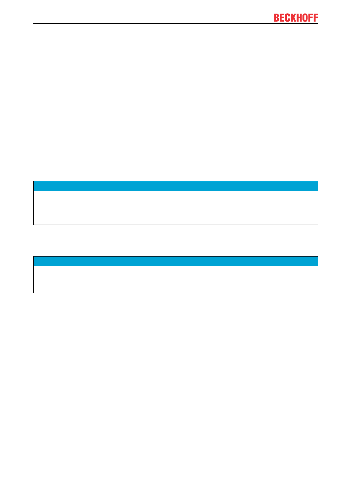
LEDs diagnosis for CX2550-0179
The following table shows the states for the LEDs of the CX2550-0179 (USB 1.1):
Display LED Meaning
PWR Power supply The Power LED lights if the device is
connected to a live power supply unit (green).
SPD Speed
The LED lights green if an USB device with full speed
( 1,5 MBit/s) is connected.
The LED lights yellow if an USB device low low speed ( 12
MBit/s) is connected.
The LED doesn`t light if the no device is connected.
15 V The LED lights (green) if 15 V is supplied to USB
extension.
SUS Suspend
The LED doesn´t light if the USB extension is operational.
The LED lights (red),if the USB extension is in suspend
mode resp. no device connected.
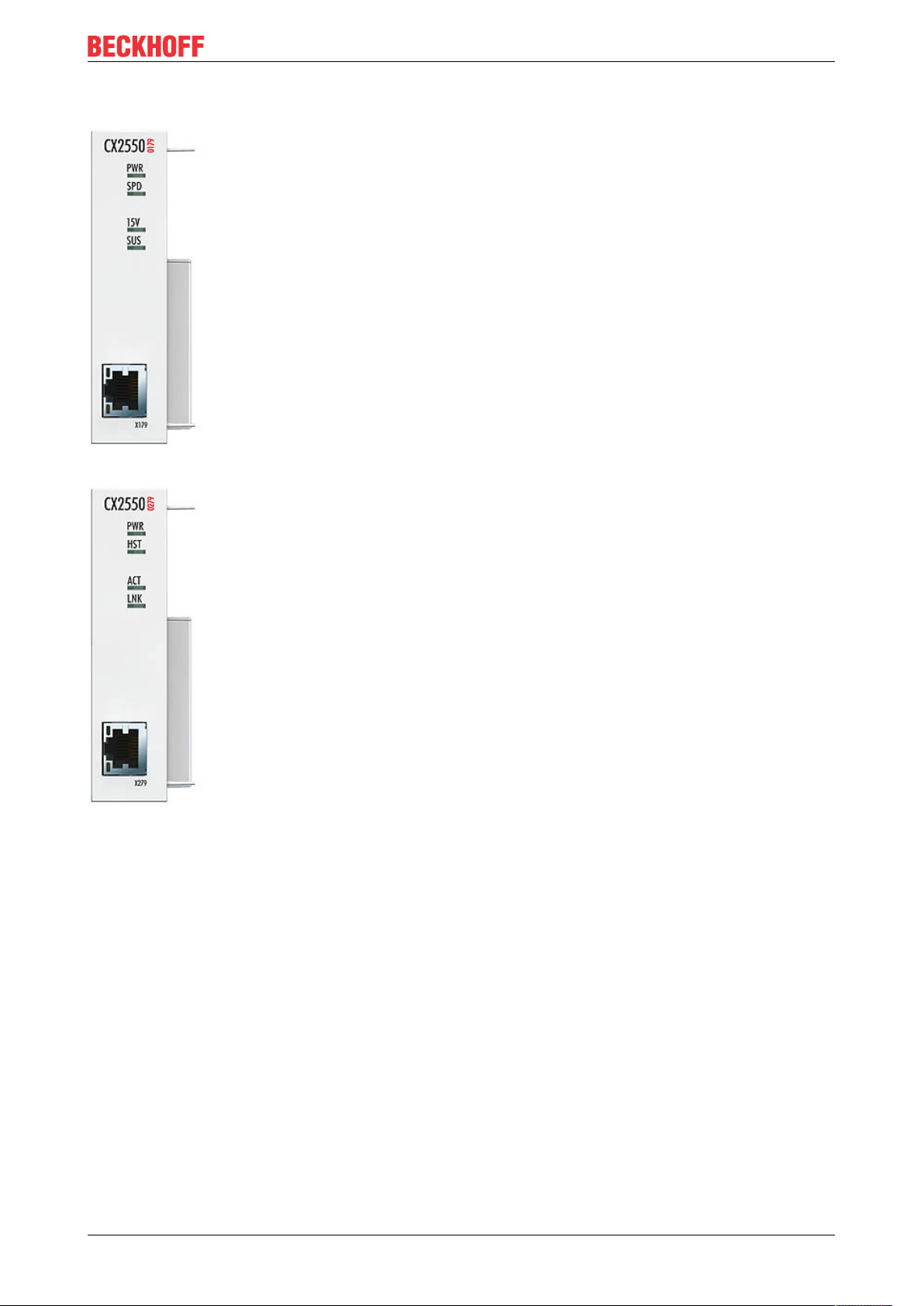
LEDs diagnosis for CX2550-0279
The following table shows the states for the LEDs of the CX2550-0279 (USB 2.0):
Display LED Meaning
PWR Power supply The Power LED lights if the device is
connected to a live power supply unit (green).
HST Host
The LED lights green if an USB host device is detected.
The LED doesn`t light if the no device is connected.
ACT Activity
The LED blinks (orange) if there is USB communication
via the USB-E extension.
The LED doesn`t light if there is no communication.
LNK Link
The LED doesn´t light if the USB extension is not
operational.
The LED lights (green) if the USB extension is connected
and running0.
CX2550-0x7922 Version: 1.0
Page 23

Error handling and diagnostics
6.2 Faults
Please also refer to the Safety instructions section.
Possible faults and their correction
Fault Cause Measures
no function after the Embedded PC
has been switched on
Embedded PC does not boot fully Hard disk damaged (e.g. due to
Computer boots, software starts,
but control does not operate
correctly
CF card access error Faulty CFast card, faulty CFast slot Use a different CFast card to check
Embedded PC only works partially
or temporarily
no power supply for the Embedded
PC
other causes
switching off while software is
running), incorrect setup, other
causes
Cause of the fault is either in the
software or in parts of the plant
outside the Embedded PC
Defective components in the
Embedded PC
1.Check the fuse
2. Measure voltage at connection,
check plug wiring, call Beckhoff
support
Check setup Call Beckhoff Support
Call the manufacturer of the
machine or the software.
the CFast slot Call Beckhoff
Support
Call Beckhoff support
Please make a note of the following information before contacting Beckhoff service or support:
1. Precise device ID: CXxxxx-xxxx
2. Serial number
3. Hardware version
4. Any interfaces (N030, N031, B110, ...)
5. TwinCAT version used
6. Any components / software used
The quickest response will come from support / service in your country. Therefore please contact your
regional contact. For details please refer to our website at www.beckhoff.de or ask your distribution partner.
CX2550-0x79 23Version: 1.0
Page 24

Decommissioning
7 Decommissioning
7.1 Disassembly and disposal
The disassembly of a CX20x0 hardware configuration with system interfaces takes place in 3 steps
1. Switching off and disconnecting the power supply
Before a CX20x0 system can be dismantled, the system should be switched off, and the power supply
should be disconnected.
2. Removing from the DIN rail
Before the individual modules are disconnected, the whole CX20x0 hardware block should be removed from
the DIN rail. Proceed as follows:
2.1. Release and remove the first Terminal next to the power supply unit on the DIN rail.
First remove any wiring from power supply unit and then from the first terminal on the DIN rail next to the
power supply unit. If the wiring is to be reused for another system, it is advisable to make a note of the
connections. Then pull the orange terminal release (see arrow) to release the terminal and pull it out.
2.2. Releasing the CX20x0 systems
In order to release the CX20x0 block, the DIN rail fastening above and below the device must be released.
To do this, press the hooks outwards using a screwdriver. An audible click indicates that the device is
released.
CX2550-0x7924 Version: 1.0
Page 25

Decommissioning
After pulling on the terminal release of the power supply unit (see arrow) the block can be carefully removed
from the DIN rail.
Disposal
The device must be fully dismantled in order to dispose of it.
Electronic parts must be disposed of in accordance with national electronics scrap regulations.
3. Disconnecting the system interface
Disconnecting the system modules from the basic module
If the modules are locked, i.e. attached with tie clips, the clips must be released. To this end lift the tie clips
with a screwdriver and pull them out. Subsequently, the system interfaces can be separated again.
NOTE
Do not use force to open the device!
Opening the module housing by force would destroy it. The devices may only be opened by Beckhoff service personnel.
CX2550-0x79 25Version: 1.0
Page 26

Appendix
8 Appendix
8.1 Certifications
All products of the Embedded PC family are CE, UL and EAC certified. Since the product family is
continuously developed further, we are unable to provide a full listing here. The current list of certified
products can be found at www.beckhoff.com.
FCC Approvals for the United States of America
FCC: Federal Communications Commission Radio Frequency Interference Statement
This equipment has been tested and found to comply with the limits for a Class A digital device, pursuant to
Part 15 of the FCC Rules. These limits are designed to provide reasonable protection against harmful
interference when the equipment is operated in a commercial environment. This equipment generates, uses,
and can radiate radio frequency energy and, if not installed and used in accordance with the instruction
manual, may cause harmful interference to radio communications. Operation of this equipment in a
residential area is likely to cause harmful interference in which case the user will be required to correct the
interference at his own expense.
FCC Approval for Canada
FCC: Canadian Notice
This equipment does not exceed the Class A limits for radiated emissions as described in the Radio
Interference Regulations of the Canadian Department of Communications.
CX2550-0x7926 Version: 1.0
Page 27

Appendix
8.2 Support and Service
Beckhoff and their partners around the world offer comprehensive support and service, making available fast
and competent assistance with all questions related to Beckhoff products and system solutions.
Beckhoff's branch offices and representatives
Please contact your Beckhoff branch office or representative for local support and service on Beckhoff
products!
The addresses of Beckhoff's branch offices and representatives round the world can be found on her internet
pages:
http://www.beckhoff.com
You will also find further documentation for Beckhoff components there.
Beckhoff Headquarters
Beckhoff Automation GmbH & Co. KG
Huelshorstweg 20
33415 Verl
Germany
Phone: +49(0)5246/963-0
Fax: +49(0)5246/963-198
e-mail: info@beckhoff.com
Beckhoff Support
Support offers you comprehensive technical assistance, helping you not only with the application of
individual Beckhoff products, but also with other, wide-ranging services:
• support
• design, programming and commissioning of complex automation systems
• and extensive training program for Beckhoff system components
Hotline: +49(0)5246/963-157
Fax: +49(0)5246/963-9157
e-mail: support@beckhoff.com
Beckhoff Service
The Beckhoff Service Center supports you in all matters of after-sales service:
• on-site service
• repair service
• spare parts service
• hotline service
Hotline: +49(0)5246/963-460
Fax: +49(0)5246/963-479
e-mail: service@beckhoff.com
CX2550-0x79 27Version: 1.0
Page 28

Page 29

More Information:
www.beckhoff.com/CX2550-0179
Beckhoff Automation GmbH & Co. KG
Hülshorstweg 20
33415 Verl
Germany
Phone: +49 5246 9630
info@beckhoff.com
www.beckhoff.com
 Loading...