

Page 1
Operation On/Off
Rate: 80 to 250 MBH
Fire or Explosion Hazard
Can cause severe injury, death or property damage
If the information in these instructions is not followed exactly, a re or explosion may
result causing personal injury, death or property damage.
─ Do not store or use gasoline or other ammable vapors and liquids in the vicinity of this
or any other appliance.
─ WHAT TO DO IF YOU SMELL GAS
y Do not try to light any appliance
y Do not touch any electrical switch; do not use any phone in your building.
y Immediately call your gas supplier from a neighbor’s phone. Follow the gas supplier’s
instructions.
y If you cannot reach your gas supplier, call the re department.
y Installation and service must be performed by a qualied installer, service agency or the
gas supplier.
Page 2
Contents
General Information ....................................................3
To the Owner: ................................................................................ 3
Owner’s Responsibility: ................................................................. 3
Professional Installer’s Responsibility: .......................................... 4
Specications ................................................................................ 4
Inspect/Prepare Installation Site ............................... 6
Indoor Installation .......................................................................... 6
Inspect Chimney and Vent System ...............................................6
Combustion Air Supply .................................................................. 8
Buildings with Adequate Air Inltration .......................................... 8
Buildings with Less Than Adequate Air Inltration ........................ 8
Clearances to Burner and Appliance .............................................8
Fuel Gas Supply ............................................................................ 9
Electrical Supply ............................................................................ 9
Verify Burner Components ............................................................9
Verify Burner Selection ..................................................................9
Prepare the Appliance ................................................11
Assemble the Burner ................................................ 12
Gather the Necessary Parts ........................................................12
Prepare the Chassis ....................................................................12
Prepare and Install the Air Tube ..................................................12
Assemble the Gas Valve and Manifold .......................................12
Install the Valve and Manifold to the Burner ................................13
Propane Applications ..................................................................13
Mount the Burner ...................................................... 16
Connect Gas Piping .................................................. 16
Wire the Burner .......................................................... 17
Sequence of Operation ............................................. 18
Prepare the Burner for Start-up ............................... 19
Start-up Checklist ........................................................................19
Start the Burner ........................................................ 19
Burner Start Procedure ..............................................................19
Verify the Firing Rate ...................................................................20
Check Operation and Safety Controls .........................................21
Use Test Instruments to Set Combustion ....................................22
Recommended Combustion Adjustment Procedure ...................22
Maintenance and Service.......................................... 23
Annual Maintenance ..................................................................23
Replace the Blower Wheel ..........................................................25
Replacement Parts .................................................... 26
Limited Warranty Information .................................. 28
Before Calling Beckett . . .
Before contacting us about your burner, you must have a completely
lled out copy of the Contractor Start-Up Form (Located inside
of last page). This information is crucial for troubleshooting and
obtaining the correct replacement part.
2
Page 3
Section: GENERAL INFORMATION
General Information
To the Owner:
This equipment must be installed, adjusted and started
by a qualied service agency that is licensed and
experienced with all applicable codes and ordinances
and responsible for the installation and commissioning of
the equipment.
Thank you for purchasing a Beckett CG4 burner for
use with your heating appliance. Please pay attention
to the Safety Warnings contained within this instruction
manual. Keep this manual for your records and provide it
to your qualied service agency for use in professionally
setting up and maintaining your burner.
Your CG4 burner will provide years of efcient operation if
it is professionally installed and maintained by a qualied
service technician. If at any time the burner does not
appear to be operating properly, immediately contact
your qualied service agency for consultation.
We recommend annual inspection/service of your
gas heating system by a qualied service agency.
Burn Hazard, Hot
Surface
Burner ange and air tube are hot
when burner is in operation. Do not
service this area during or immediately
after operation. Allow area to cool.
Owner’s Responsibility:
Explosion, Fire,
Asphyxiation Hazard
Failure to follow these instructions,
misuse, or incorrect adjustment of the
burner could lead to equipment
malfunction and result in
asphyxiation, explosion or re.
Contact a professional, qualied service agency for
the installation, adjustment and service of your gas
burning system. Thereafter, have your equipment
adjusted and inspected at least annually to ensure
reliable operation. This work requires technical
training, trade experience, licensing or certication
in some states and the proper use of special
combustion test instruments.
Please carefully read and comply with the following
instructions:
y See the front cover for ‘What to do if you smell gas’.
y Never store or use gasoline or other ammable
liquids or vapors near this burner or appliance.
y Never attempt to burn garbage or refuse in this
appliance.
y Never attempt to light the burner/appliance by
throwing burning material into the appliance.
y Never attempt to burn any fuel not specied and
approved for use in this burner.
y Never restrict the air inlet openings to the burner or
the combustion air ventilation openings in the room.
CG4 Burner Manual
Frozen Plumbing and
Water Damage Hazard
If the residence is unattended in severely cold
weather, burner primary control safety lockout,
heating system component failures, power
outages or other electrical system failures could
result in frozen plumbing and water damage in a
matter of hours. For protection, take preventive
actions such as having a security system installed
that operates during power outages, senses low
temperature and initiates an effective action.
Consult with your heating contractor or a home
security agency.
Contact a professional, qualied
service agency to replace any
component that has been exposed to water.
3
Page 4
Section: GENERAL INFORMATION
Professional Installer’s Responsibility:
Professional Service
Required
Failure to follow these instructions
could lead to equipment malfunction
and result in asphyxiation, explosion
or re.
y Please read all instructions before proceeding.
Follow all instructions completely.
y This equipment must be installed, adjusted
and started by a qualied service agency that
is licensed and experienced with all applicable
codes and ordinances and responsible for the
installation and commissioning of the equipment.
y The installation must comply with all local codes
and ordinances having jurisdiction and the latest
edition of the National Fuel Gas Code ANSI
Z223.1 (NFPA 54) and CAN1-B149.1 in Canada.
Fire Hazard: Overheating
Should over-heating occur:
y Shut off the manual gas control to
the appliance.
y DO NOT shut off power to the
equipment, allow the blower and
pumps to continue running.
Specications
Table 1 – Burner Specications
Input Firing Rate 80,000 - 250,000 BTU/hr
Firing Mode On-Off Only
Fuel
Required Input Gas Supply
Pressure
Input Voltage 120 Vac + 10% / -15%; 60 Hz
Input Current 2.75 A (Run); 12.0 ALR
Gas Valve
Burner Control Beckett 7590D Direct Ignition
Flame Detection Flame Rectication
Igniter Beckett 7474001 Gas Igniter
Motor 1/7 Hp; PSC
Combustion Air Proving Differential Pressure Switch
Weight 55 lbs.
Mounting Orientation
Dimensions 10.3” x 13.1” x 15.8”
Acceptable Ambient
Temperature Range
Acceptable Ambient Humidity 5% - 95% RH non-condensing
For altitudes higher than 2,000 feet, derate the burner capacity 4%
for each 1,000 feet above sea level.
Burner is not approved for use in 50 Hz applications.
Natural gas - 0.64 specic gravity
LP gas - 1.53 specic gravity
4.5” WC minimum
14” WC maximum
24 Vac Dual Seat with integral regulator
set to 3.5” WC for both natural gas and
LP
Up to 90° from upright with motor shaft
horizontal
-40°F to 150°F
Special Requirements:
When contacting Beckett for
service information — Please have the burner serial
number and contractor start-up form available when
calling or writing. You will nd the serial number on
the label located on the left rear of the burner. Refer
to Figure 2.
Concealed damage – If you
discover damage to the burner
or controls during unpacking, notify the carrier at
once and le the appropriate claim forms. Do not
install a burner or control that has been damaged.
If any of these instructions are not clear,
Call Beckett at 1-800-645-2876 for assistance.
For use only on approved
applications. See www.
beckettcorp.com/cg4apps for the list of approved
applications.
ETL listed for use in the US or
Canada per ANSI Z21.17(a) / CSA
2.7(a) For use with natural gas or
propane.
4
Page 5
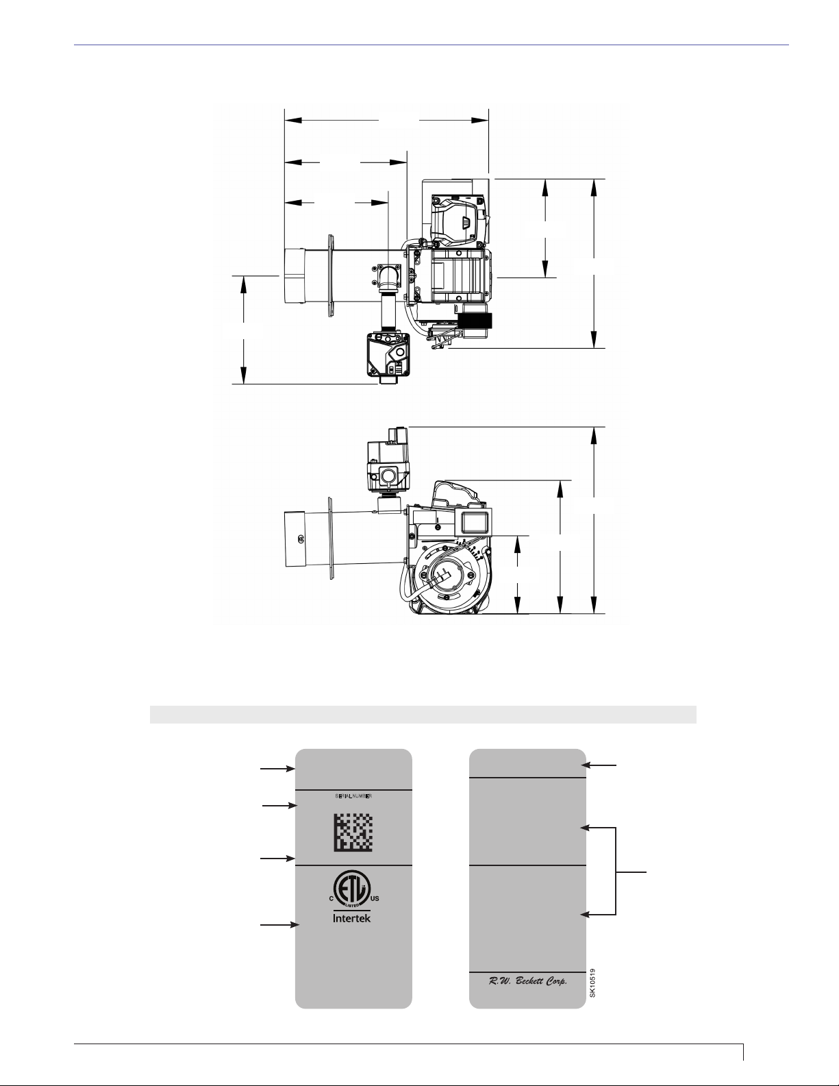
1.13
Figure 1 – Burner Dimensions
8.3”
Section: GENERAL INFORMATION
15.8”
9.5”
8.0”
7.6”
13.1”
Figure 2 – Burner Nameplate
Your burner will have labels that are specic to its construction. This is for reference only.
General Model Information
Serial Number
R.W. Beckett Specication
Number and Revision
Approvals / Certications
Model “CG4”
Gas ConversionBurner
Brûleur de conversion
SERIAL NUMBER
140121-08157
CG4001 Rev.A 00
#########
Conforms to ANSI Std
Z21.17
Certified to CSA Std
En conformité avec la norme
Homologation en vertu de la
2.7
ANSI Z21.17
norme CSA 2.7
14.4”
10.3”
6.0”
80 TO 250 MBH, 24 to 73 kW
120V/60Hz, 3A run, 12A LR
For use with natural gas or
propane. A conversion kit
supplied by the manufacturer shall
be used to convert to the alternate
fuel.
Manifold pressure: 3.5” W.C.
Max press. to valve: 1/2 PSI
Min press. to valve: 4.5” W.C.
A utiliser avec du gas naturel ou
du propane. Se servir de la
trousse de conversion fournie
par le fabricant pour paser d’un
type decarburant à l’autre.
Pression d’admission: 870 Pa
Pression max.’ à la soupape:
3450 Pa
Pression min. à la soupape:
1120 Pa
Elyria, Ohio
Made in the U.S.A.
Rating Information
Fuel, Construction,
and Setting Data
CG4 Burner Manual
5
Page 6
Section: INSPECT/PREPARE INSTALLATION SITE
Inspect/Prepare
Installation Site
Indoor Installation
Explosion, Fire,
Asphyxiation Hazard
Wet or dusty environments could lead
to blocked air passages, corrosion
damage to components, impaired
combustion performance and result in
asphyxiation, explosion or re.
y This burner is designed for clean, dry
installations.
y Electrical controls are not protected against rain
or sprayed liquids.
y Keep the installation clear of dust, dirt, corrosive
vapors, and moisture.
y Protective covers and frequent maintenance may
be required.
Fire, Smoke &
Asphyxiation Hazard
y Carefully inspect the chimney,
chimney liner & exhaust vent system.
y Make sure it is properly sized and in
good working condition.
y Follow the instructions supplied by
the appliance manufacturer.
y If a draft regulator is required, it must be a
double-acting type, agency recognized for use
with gas vent systems.
y The chimney installation and vent sizing
must strictly comply with all applicable codes,
authorities having jurisdiction and the latest
revision of the National Fuel Gas Code (ANSI
Z223.1, or NFPA54) or CAN/CGA B/49 Canada.
Remove any vent damper device.
y Regulation by these authorities take precedence
over the general instructions provided in this
installation manual.
Examine the installation site for conditions that could
adversely affect the health and safety of installation
personnel and the user of the appliance or proper
operation of the burner and appliance, and correct any
defects found.
○ The area around the appliance should be
unobstructed and dry.
○ Wiring must be in good condition and meet code
requirements.
○ If the burner is replacing an existing oil burner, old
piping and the tank must be secured or removed to
prevent leakage or unintended deliveries of oil.
○ Local jurisdictions may require removal of oil tanks.
See NFPA-30 ammable and combustible liquids
code for approved procedures.
Inspect Chimney and Vent System
1. Any accumulation of soot or debris in chimney
offsets must be removed
2. Any obstructions such as a protruding joint or a
piece of broken tile wedged in the chimney must be
removed.
3. No other appliance connection should be made to
the same ue pipe.
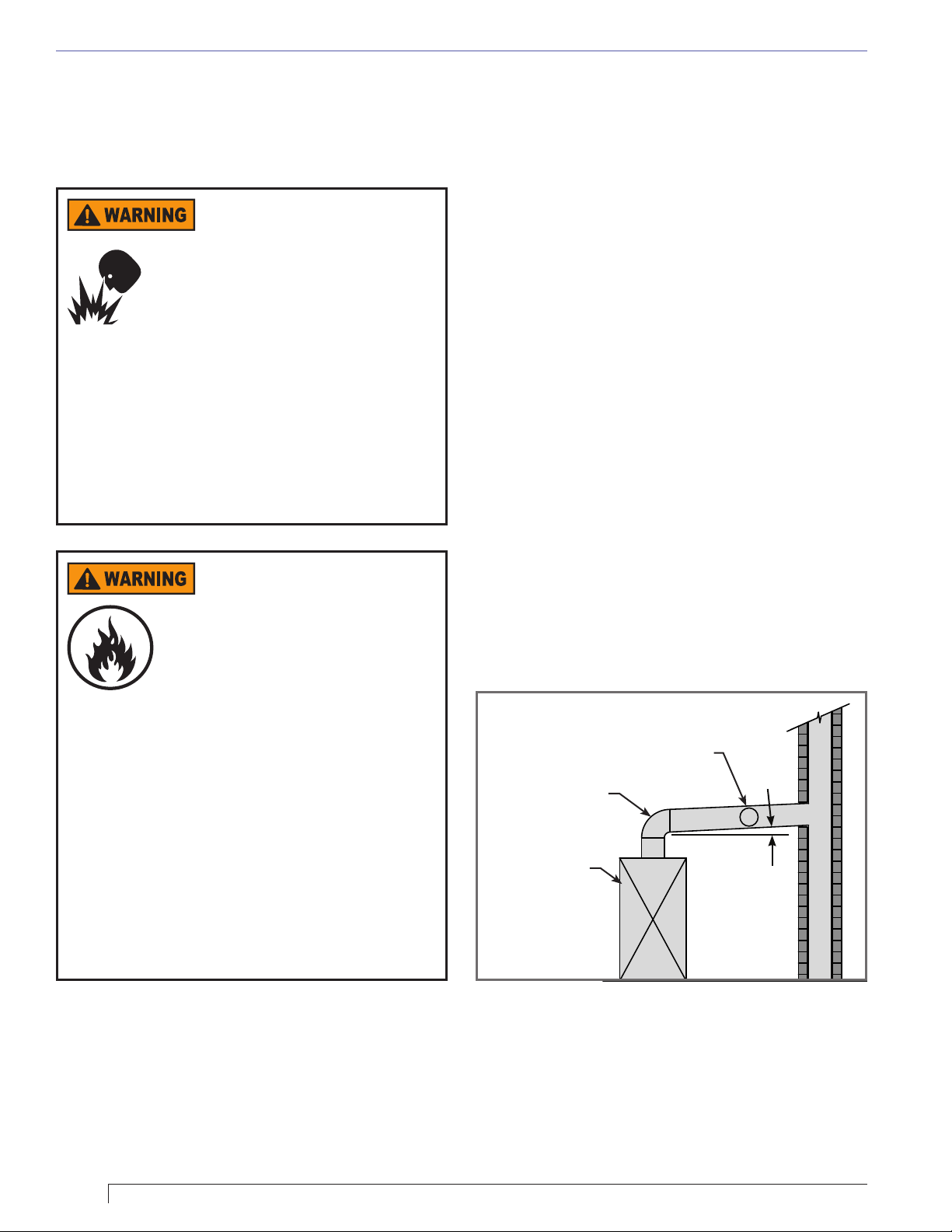
4. The ue pipe should have an upward pitch toward
the chimney of at least 1/4” per foot of length. It
should t tightly and should not project into the
chimney, see Figure 3.
Figure 3 – Vent Pipe with Draft Regulator
Barometric Draft Control
Flue Pipe Ell
Heating Unit
1/4” per Foot
Minimum
6
Page 7
Section: INSPECT/PREPARE INSTALLATION SITE
5. Any leakage between tiles, around clean-out doors,
or around the vent pipe should be sealed.
6. A Draft regulator is required, it shall be a double-
acting type, agency recognized for use with gas
vent systems.
7. The design and sizing of the appliance’s vent
system shall comply with the requirements of NFPA
54 Chapters 12 and 13.
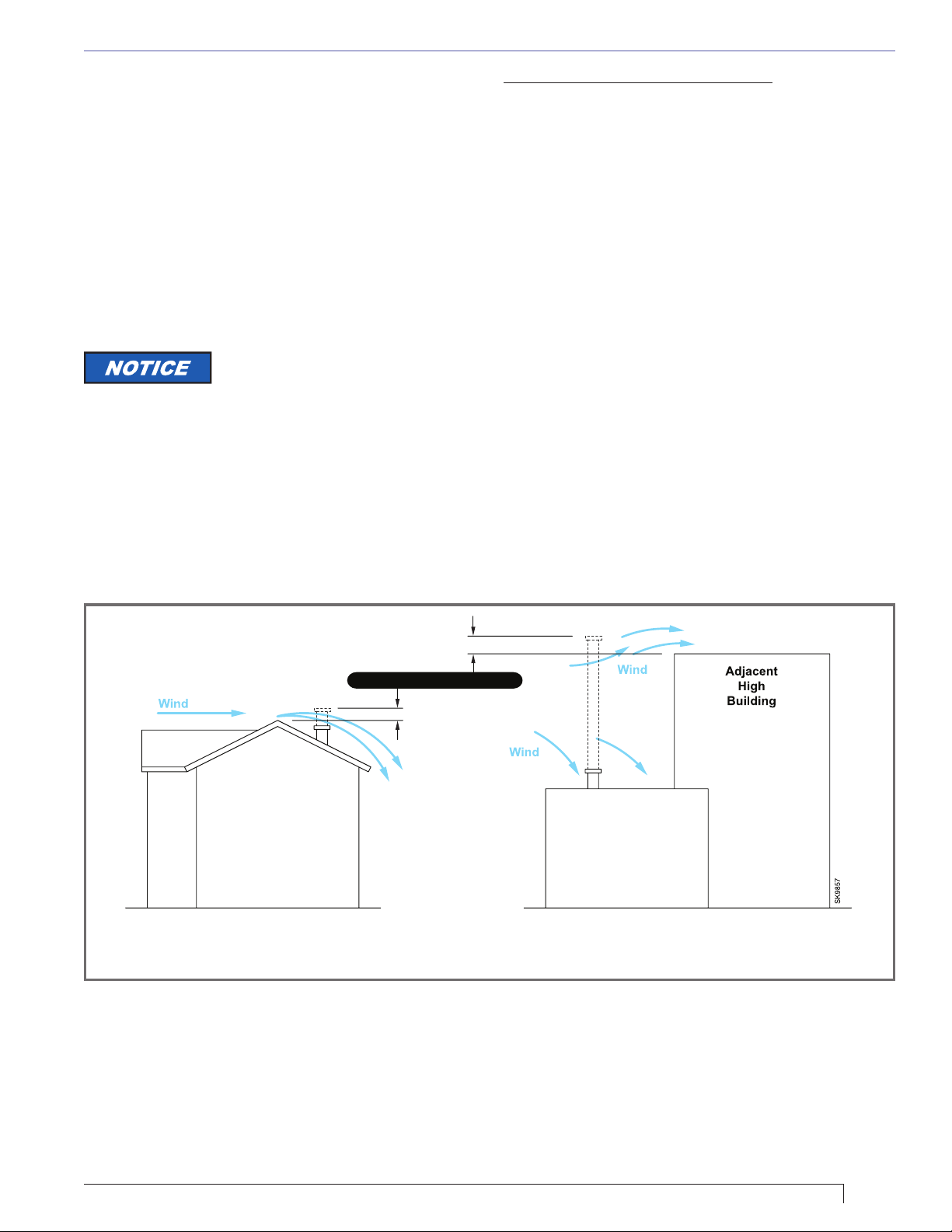
8. A chimney ue shall extend at least 3 feet above
the highest point at which the chimney comes in
contact with the roof, and not less than 2 feet above
the highest roof surface or structure within 10 feet
horizontally of the chimney. Refer to Figure 4.
Some local codes and gas
utilities require the installation of
a thermal Safety switch on the double-acting draft
control, or draft hood. This is a very good practice
and provides the following protection:
The thermal safety switch senses ue gas spillage
caused by blocked ue exhaust, prolonged down-draft,
or insufcient draft. The safety is wired in series with the
burner control circuit and shuts the burner off, when the
spillage of hot ue gases is detected.
Insulated stainless steel chimney liners
The new designs of furnaces and boilers in conjunction
with ame retention gas burners are more efcient.
One result of increased efciency is lower ue gas
temperatures. As ue gases rise in the chimney, they
cool and condense when they reach the dew point.
The condensation mixes with sulphur in the ue gases
creating sulfuric acid. The acid attacks the chimney
mortar, brick and clay liners causing corrosion,
deterioration and blockage of the chimney. Eventually
the blockage could prevent exhausting the ue gases.
Instead, the ue gases vent out the barometric damper
into the living space.
Therefore it is strongly recommended that an approved
insulated stainless steel chimney liner be installed. The
installing contractor is solely responsible for installation
of the proper vent system.
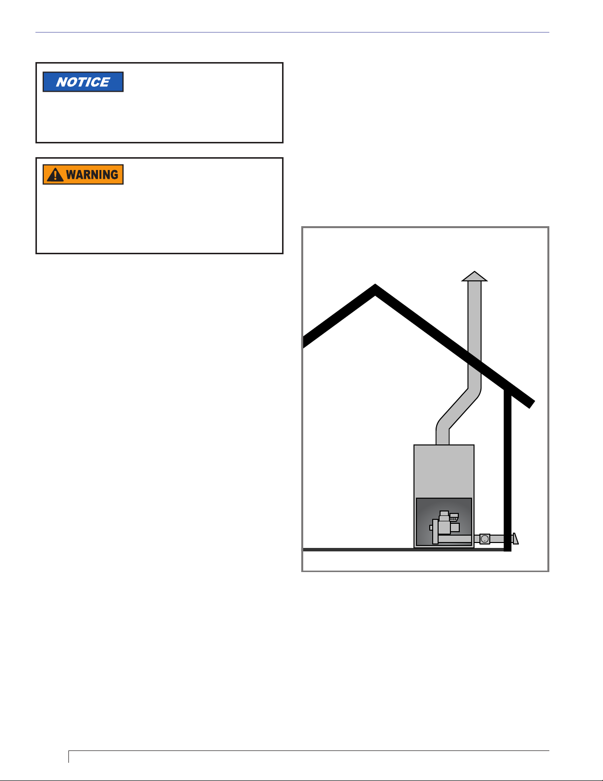
○ For those installations not requiring a chimney, such
as through-the-wall vented appliances, follow the
instructions given by the appliance and power venter
(if used) manufacturers.
Figure 4 – Chimney Design - Above the Roof
Minimum Clearence: 2 FT.
NOTE: Correct chimney design is shown by dotted lines. Incorrect chimney design, as shown by the solid
lines, may result in down-drafts.
CG4 Burner Manual
7
Page 8
Section: INSPECT/PREPARE INSTALLATION SITE
Combustion Air Supply
Some local codes and
gas utilities require the
installation of a CO detector, this is
strongly recommended in all
applications.
Carbon Monoxide
Hazard
Do not block combustion air inlet. Failure to
provide adequate air supply could seriously affect
the burner performance and result in damage to
the equipment and emission of poisonous carbon
monoxide gas.
Buildings with Adequate Air Inltration
In many cases, a burner operating in an unconned
space of a conventional frame, brick or stone building
will receive adequate air supply from leakage in the
building itself. But if the burner is located in a conned
space such as a furnace or boiler room, that space
must have one permanent opening toward the top of the
space and one near the bottom of the space.
One method to accomplish this is through a permanent
opening(s) in an exterior wall. The opening, or openings,
must have a total free area of not less than one sq. in.
per 5,000 BTU per hour. All appliances must be taken
into consideration. Refer to NFPA 54 & 58.
Another method is to supply outside air directly to the
burner through round, smooth duct work (See Figure
5). Some manufacturers offer accessories which allow
outside combustion air duct work to be coupled to the
burner. These kits must meet the engineered system
requirements of NFPA54. For safety reasons it is
important that you comply strictly with their installation
instructions.
Figure 5 – Outdoor Air Ducted to Burner
Each opening must have a free area of not less than one
sq. in. per 1,000 BTU per hour of the highest input rating
listed for the appliance (refer to NFPA 54 & 58).
Remember to take the total input of all air-using
appliances into consideration when guring the
openings. The openings must connect with the inside of
the building, which should have adequate inltration from
the outside.
As an example:
If a gas burner was ring at 175,000 BTU/Hr and a water
heater was ring at 70,000 BTU/Hr, in an enclosed room
in a building each opening in the enclosure should be
245 sq. in. (245,000/1,000 x 1 sq. in. = 245 sq. in.) A
245 sq. in. opening would typically be 10” x 25” or 16” x
16”.
Buildings with Less Than Adequate Air
Inltration
If the burner is located in a tightly constructed building
where there is inadequate outside air inltration, outside
combustion air must be supplied by some other means.
Clearances to Burner and Appliance
○ Provide space around burner and appliance for easy
service and maintenance.
○ Check minimum clearances against those shown
by the appliance manufacturer and by applicable
building codes.
○ The recommended clearance around the burner
itself is 12” minimum for service access.
8
Page 9
Section: INSPECT/PREPARE INSTALLATION SITE
Fuel Gas Supply
Explosion, Fire,
Asphyxiation Hazard
Leaking gas could result in asphyxiation,
explosion, or re hazard.
Prior to burner installation all gas supply piping must be
inspected, tested and purged in accordance with the
requirements of the National Fuel Gas Code ANSI Z
223.1 (NFPA 54).
The burner valve must not be exposed to pressure
exceeding 1/2 PSI under any circumstances.
Insure that the supply gas pipe size is capable of
providing at least 4.5” W.C. pressure to the burner gas
train inlet at the burner’s full capacity rating. Refer to
Tables 2 and 3.
Table 2
Gas Supply Pressure Requirements (Natural or Propane)
Maximum 14” WC (1/2 PSI)
Minimum 4.5” WC
Explosion, Fire, and Gas
Leak Hazard
A Drip Leg is required in Gas Supply
Piping. Foreign matter could lodge in gas
valve cutoff seals, resulting in gas leak-
through, explosion or re.
Insure that a full-size drip leg or dirt pocket has been
installed in the piping directly ahead of the main shutoff
valve to capture foreign matter.
Electrical Supply
Check the nameplate on the burner to verify that the
power connections available are correct for the burner.
Refer to Figure 2 on Page 5. All power must be
supplied through a disconnect switch fused at 20A
maximum and comply with the latest edition of National
Electric Code NFPA 70 (Canada CSA C22.1) and all
other local or applicable codes.
Verify Burner Components
Your CG4 burner is shipped in two boxes. Verify that
you received all the necessary components.
Table 3 – Gas supply piping capacity, CFH
Schedule 40 metallic pipe with 0.50 psi or less inlet pressure
and 0.30” W.C. pressure drop
Maximum capacity in cubic feet of gas per hour (CFH). Natural
gas with 0.60 specic gravity.
Pipe
Length
(ft.)
10 132 278 520 1050 1600
20 92 190 350 730 1100
30 73 152 285 590 890
40 63 130 245 500 760
50 56 115 215 440 670
60 50 105 195 400 610
70 46 96 180 370 560
80 43 90 170 350 530
90 40 84 160 320 490
100 38 79 150 305 460
110 34 72 130 275 410
120 31 64 120 250 380
150 28 59 110 225 350
1/2” 3/4” 1” 1-1/4” 1-1/2”
Pipe size (inches) IPS
The larger box contains:
○ The burner chassis
○ The literature package, which includes the burner
manual
○ The gas valve
○ A small parts bag, containing a reducing tee, a pipe
plug, a union and a bafe (P/N 5880)
The smaller box contains:
○ The air tube
○ The burner head and its (2) mounting screws
○ A blank air band (only packaged with tubes using the
F3G head)
○ A box containing the manifold assembly, the natural
gas orices, an O-ring, a packet of O-ring lubricant
and 10 mounting screws.
Verify Burner Selection
If the burner is supplied as an original equipment part
of a boiler or furnace appliance the information in this
section may be disregarded. Instead, use the appliance
manufacturer’s specications.
If the gas supply pressure is not correct, it must be
corrected before starting the CG4 installation. Contact
your gas utility or qualied contractor.
CG4 Burner Manual
Verify that the proper burner chassis and air tube
assembly have been selected.
○ Determine the appliance’s design ring rate from the
appliance rating plate. The appliance rating plate will
probably have an input rating and an output rating.
9
Page 10

Section: INSPECT/PREPARE INSTALLATION SITE
Table 4 – Minimum Combustion Chamber Dims.
Chamber Dimensions (Inches)
Firing
Rate
MBH
80 8 8 9 13 4
105 9 9 10 13.5 4.5
140 10.5 10.5 12 14 5.3
175 11.5 11.5 13 14.5 5.8
210 13 13 14.5 15 6.5
250 15 15 16 16 7.5
Rectangular
Width
(W)
Height
(H)
Horizontal
Cylinder
I. D.
Length
(L)
Floor to
Tube (A)
Table 5 – Firing Rates and Congurations
H
W
L
A
Fuel Orices
Firing Rate
BTU/Hr.
80,000 0.219 0.166 F3G 01 32910-001 5880 Blank 2-1/2 Blank
90,000 0.234 0.177 F3G 01 32910-001 5880 Blank 4 Blank
100,000 0.25 0.189 F3G 01 32910-001 5880 Blank 5-1/2 Blank
110,000 0.277 0.206 F3G 01 32910-001 5880 Blank 7-1/2 Blank
120,000 0.316 0.219 F3G 01 32910-001 5880 4-slot 9 0
130,000 0.364 0.234 F3G 01 32910-001 n/a 4-slot 5-1/2 0
140,000 N/A 0.242 F3G 01 32910-001 n/a 4-slot 7-1/2 0
130,000 0.281 0.217 F4G 02 32910-001 5880 4-slot 8 0
145,000 0.316 0.234 F4G 02 32910-001 5880 4-slot 10 0
160,000 0.348 0.246 F4G 02 32910-001 n/a 4-slot 6-1/2 0
175,000 0.406 0.261 F4G 02 32910-001 n/a 4-slot 8-1/2 0
190,000 N/A 0.281 F4G 02 32910-001 n/a 4-slot 10 0
180,000 0.332 0.246 F6G 03 n/a n/a 4-slot 5-1/2 0
190,000 0.354 0.256 F6G 03 n/a n/a 4-slot 7 0
205,000 0.377 0.266 F6G 03 n/a n/a 4-slot 8-1/2 0
220,000 0.422 0.281 F6G 03 n/a n/a 4-slot 10 0
235,000 0.484 0.295 F6G 03 n/a n/a 4-slot 10 2
250,000 N/A 0.312 F6G 03 n/a n/a 4-slot 10 4
Natural Gas
Orice Dia.
Inches
L P Orice
Dia. Inches
Air Tube Components
Burner
Head
Nozzle Static Plate Bafe Band Shutter Band
Chassis
Components
Initial Settings
- Firing rates are based on 3.5” WC manifold gas pressure and use of the appropriate orice for the fuel being red.
- Air tube assemblies are provided with a full selection of the natural gas orices appropriate to the burner head.
- LP orices are provided in kits containing all the LP orices for the burner head size. The installer is responsible
for selecting and installing the appropriate orice for the application.
- Burner heads and nozzles are identied with the markings shown to assure the use of compatible combinations.
- Burner chassis are built for the highest rate conguration. The installer is responsible to add the bafe and/or
change the band as required for the application.
- Initial settings are intended for use only as a starting point for burner adjustments. They can not make provision
for all installation possibilities. It is important that you adjust your burner to your installation requirements using
properly calibrated ue gas analysis instruments.
10
Page 11

Section: INSPECT/PREPARE INSTALLATION SITE
The burner’s ring rate is the input rating. If it is
given in GPH of oil, multiply by 140,000 to get BTU/
Hr for gas or by 140 to get MBH.
○ The burner’s ring rate must be no more than 5%
higher than the appliance’s stated input rate (based
on industry tolerance) and no more than 10% lower
than the appliance’s stated input rate (based on the
potential for low stack temperature condensation
hazards).
○ Determine the burner’s appropriate chassis and air
tube components from Table 5, being sure to apply
the altitude adjustment from Table 1 on Page 4,
if applicable.
○ Verify that the chassis has the correct air band and
bafe (if required)
○ Verify that the air tube has the correct head and
nozzle (markings are visible without disassembly)
and static plate (there is only one choice, and it is
visible without disassembly).
○ Verify that you have the correct fuel orice for the
intended ring rate (Table 5) – sizes are stamped on
the orices
○ Examine the appliance’s combustion chamber and
compare its dimensions to the rate-appropriate line
in Table 4 to verify that the chamber is large enough
to handle the ame size.
○ Examine the appliance’s mounting dimensions and
compare them to those of the mounting ange on
the air tube, making sure that the distance from
the ange to the furnace end of the burner head
provides for the ¼” set-back shown in Figure 11 on
Page 16.
Carbon Monoxide
Hazard
DO NOT INSTALL a Beckett gas burner and air
tube combination with a ring rate more than 10%
lower than the appliance name plate’s input BTU
rating. The appliance and vent system could be
damaged due to condensation, leading to ue gas
leakage.
Prepare the Appliance
Breathing Hazard
Ceramic ber or Fiberglass insulation
Ceramic ber materials, such as chamber
liners, may contain carcinogenic particles
(crystalline silica) after exposure to
heat. Airborne particles from berglass
or ceramic ber components have been
listed as potentially carcinogenic by the
State of California. Take the following precautions when
removing, replacing and handling these items.
Avoid breathing dust and avoid contact with skin
or eyes. Wear long-sleeved, loose-tting clothing,
gloves and eye protection. Use a NIOSH N95 certied
respirator. This respirator meets requirements for
protection from crystalline silica. Actual job requirements
for NIOSH regulations may require other or additional
protection. For information, refer to the NIOSH website,
http://www.cdc.gov/niosh/homepage.html.
Ceramic ber removal: To prevent airborne dust,
thoroughly wet ceramic ber with water before
handling. Place ceramic ber materials in a plastic
bag and seal to dispose.
Avoid blowing, tearing, sawing or spraying
berglass or ceramic ber materials. If such
operations are necessary, wear extra protection to
prevent breathing dust.
Wash work clothes separately from other laundry.
Rinse clothes washer thoroughly afterwards to
prevent contamination of other clothing.
NIOSH First aid procedures:
y Eye exposure - irrigate eyes immediately
y Breathing - fresh air
Asbestos Hazard
DO NOT INSTALL a Beckett
gas burner and air tube
combination with a ring rate more than 5% above
the appliance name plate’s maximum input BTU
rating.
CG4 Burner Manual
NEVER attempt to retrot an
appliance containing asbestos.
Contact a professional to remove the
asbestos prior to installation. If
unsure call a qualied contractor to
verify if asbestos is present.
Thoroughly clean appliance heat exchanger and replace
damaged combustion chamber materials, if necessary.
○ Seal all clean-outs, burner mounting plate and vent
pipe connections.
○ Verify all appliance operating and safety controls are
functional and operating correctly. Replace any that are
questionable.
○ Verify all wiring and controls comply with National/Local
codes and authorities having jurisdiction.
11
Page 12

Section: PREPARE THE APPLIANCE
Fire and Asphyxiation
Hazard
Failure to comply with manufacturer’s
instructions could result in damage to the
stainless steel combustion chamber
which can result in re or asphyxiation
hazards.
If retrotting a CG4 to a stainless steel combustion
chamber, check the appliance manufacturers instructions
to determine if a lining is required and comply with their
recommendations.
Assemble the Burner
Gather the Necessary Parts
1. You have already veried that you received all the
components shipped with the burner.
2. In addition to the parts provided with the burner you
will need ¾” pipe nipples (schedule 40, black iron –
do not use galvanized) to make up the connection
to the supply piping, and pipe joint compound. Pipe
lengths must be selected to t your installation. We
recommend a 3” to 6” length between the gas valve
and the union.
Prepare the Chassis
1. Determine whether you must add a bafe using the
appliance’s ring rate and Table 5 on Page 10.
2. If a bafe must be added, open the burner’s top
access cover by loosening the two front screws and
pivoting their clips out of the way.
3. Align the bafe between the two pins on the motor
side of the housing (Figure 6 on Page 13) and
against the housing partition and tap it securely
onto the partition.
4. Determine whether you must change from the 4-slot
air band shipped on the chassis to the blank air
band using the appliance’s ring rate and Table 5.
5. If the air band must be changed, remove the air
proving switch, the shutter and the slotted band
(Figure 7 on Page 14).
6. Install the blank band and return the shutter and
air proving switch in the reverse order from step 5,
tightening the screws securely.
Prepare and Install the Air Tube
1. The air tube may be shipped without the head
installed. If so, align the openings in the swirl vanes
with the ame rod and ignition electrodes and
press the head onto the OD of the air tube until the
head is seated and the screw holes on the sides
align. Use care to avoid bending the swirl vanes or
the front edge of the shroud. Install the retaining
screws packed with the head and tighten securely.
2. Remove 2 screws from the housing end of the air
tube that secure the rear edge of the gas gun.
3. Install the air tube onto the housing with the gas
connection on the top side of the air tube (Figure
8). Install the (4) ¼-20 screws nger tight. Install
the remaining 4 screws. After all 8 screws are in
place tighten them all securely.
4. Route the ignition (black) and ame sensing
(yellow) wires from the air tube into the chassis.
5. Connect the yellow (ame sense) wire from the
air tube to the yellow wire in the chassis, and take
up all slack in the wire by pushing it back into the
electrical box.
6. Connect the black (ignitor) wire to the igniter with
the access cover partially closed. Close the cover,
secure it with its retaining clips, and tighten the clip
screws securely.
Assemble the Gas Valve and Manifold
1. You will need to provide a ¾” schedule 40 black
iron pipe nipple (3” to 6” long is convenient) and
joint compound to complete this assembly. Refer to
Figure 9 on Page 15.
2. Install the factory assembled burner manifold
(mounting block, 2 nipples and elbow)on the
outlet side of the valve (the side the arrows point
towards), following the valve manufacturer’s piping
instructions supplied with the valve.
3. Install a ¾” pipe nipple and union on the inlet side
of the valve, following the valve manufacturer’s
piping instructions supplied with the valve.
The gas valve is sensitive to
its installation orientation.
It must only be installed in horizontal piping
with its electrical connections on top as
shown in Figures 9 and 10.
Explosion, Fire, and Gas
Leak Hazard
y Do not disassemble gas valve
y Do not use Teon tape on gas piping.
Damage to gas valve seats and bodies
could cause gas leaks and result in
asphyxiation, explosion, or re.
y Valve must be installed with ow direction arrow
pointing to burner.
12
Page 13

Section: ASSEMBLE THE BURNER
Pieces of tape can be cut loose during installation and
lodge in gas valves causing cutoff seal problems.
Teon tape lubricates pipe threads, allowing iron pipes to
penetrate too deeply into aluminum valve bodies causing
distortion and leakage.
Use only pipe sealant compounds that are resistant to
the gas being used.
Verify that the gas valve
is not damaged and that
all piping and ttings are de-burred and
clean inside and out.
Install the Valve and Manifold to the Burner
1. Determine the correct fuel orice using the
appliance’s fuel type, ring rate and Table 5 on
Page 10, and insert it into the recess in the
manifold adapter on the top of the burner’s air tube
(Figure 10 on Page 15). Notice in Table 5 that
not all natural gas applications use a fuel orice.
2. Lubricate the O-ring with the small packet of
lubricant provided and install it into the groove on
the bottom of the manifold mounting block.
3. You may mount the manifold assembly with the
valve on either the right or left side of the burner
(Figure 10). Tighten its screws securely.
4. Connect the violet and white wires (from the
electrical box adjacent to the air tube) to their
mating spade terminals on the top of the gas valve.
The white wire goes to the terminal marked “C” and
the violet wire goes to the terminal marked “MP”.
With the propane orice
installed, as shown in Figure
10 , Page 15, all burner air adjustments and
gas manifold pressure adjustments for propane
will be approximately the same as the natural gas
adjustments shown in the burner manual, or printed
on the “Mfr’s Settings” label on the burner housing.
For a copy of the current burner manual go to http://
www.beckettcorp.com/protect/tech.asp. If further
technical assistance is required, call 800-645-2876,
Monday thru Friday, 8AM to 5PM EST.
Explosion, Fire and
Asphyxiation Hazard
This
conversion kit must be installed
by a qualied service agency in
accordance with the manufacturer’s
instructions and all applicable codes
and requirements of the authority
having jurisdiction.
(In Canada, in accordance with the requirements
of the CAN/CGA-B149 Installation Code.) If the
information in these instructions is not followed
exactly, a re, explosion, or production of carbon
monoxide may result causing property damage,
personal injury or loss of life. The qualied service
agency is responsible for the proper installation of
this kit. The installation is not proper and complete
until the operation of the converted appliance
is checked, as specied in the manufacturer’s
instructions supplied with the kit.
Figure 6 – Bafe Installation
Propane Applications
Beckett CG4 burners are designed to re either natural
gas or propane gas by changing only the fuel orice
(Figure 10, Page 15). Table 5 on Page 10 lists the
correct fuel orices for both fuels by ring rate together
with the other rate-variable components of the burner.
All the burner’s adjustments and settings for propane will
be the same as for natural gas when the appropriate fuel
restrictors are in place. For ANSI Z21.17a purposes, the
propane restrictors listed in Table 5 are considered to be
Beckett’s propane conversion kits.
Use authorized replacement
parts only. Fuel orices are
precision-machined parts and O-rings are rated for
fuel contact. Do not attempt to replicate or modify any
parts. Refer to Table 5 on Page 10.
CG4 Burner Manual
Partition
Alignment
Pins
13
Page 14

Section: ASSEMBLE THE BURNER
Figure 7 – Installation of air band, shutter, and air provings switch
Slotted Air Band
Air Proving Switch
Blank Air Band
Figure 8 – Air Tube Installation
Air Tube
Shutter
#10-24 x 1/2” Button Socket
Head Screws (Qty: 2)
#8 x 7/16” Hex Washer
Head Screws (Qty: 2)
14
Gas Connection on Top
1/4-20 x 5/8” Hex Head Screws (Qty:4)
Page 15

Figure 9 – Gas Manifold
3/4” Pipe Nipple
(Installer Provided)
Section: ASSEMBLE THE BURNER
Manifold (Factory
Assembled)
Union
Figure 10 – Gas Manifold Installation
#10-24 x 1-1/4” Button Socket
Head Screws (Qty: 4)
Flow Arrow Points
This Way
O-Ring (Lubricate Before Installing)
Fuel Orice (If Used)
CG4 Burner Manual
15
Page 16

Section: MOUNT THE BURNER
Mount the Burner
Mount the burner to the appliance. The burner specied
for packaged equipment will have a ange welded for the
required insertion. Follow the appliance manufacturer’s
instructions for mounting.
Protect the Air Tube
from Overheating
Overheating could cause damage to the air tube
and other combustion components leading to
equipment malfunction and impaired combustion
performance.
1. Verify the Burner’s Insertion Depth
The end of the air tube should be set back ¼”
from ush with the refractory inside wall to prevent
damage from overheating (See Figure 11).
The end of the air tube must not extend into the
combustion chamber unprotected unless it has
been factory-tested and specied by the appliance
manufacturer.
Connect Gas Piping
Install the test cock tee, its plug, and the union (provided
with the burner) into the supply piping and connect them
to the burner valve and manifold (Figure 12).
Gas supply piping must be
structurally supported
independant of the burner. The burner manifold and
gas valve are not designed to support piping loads.
Figure 12 – Typical Gas Piping Layout
KEY
Abbrev. Item Description
MSC Main Shutoff Cock
TC Test Cock
U Union
GV Gas Valve
DL Drip Leg
Provided by Installer
2. Bolt the burner to the appliance using the factory-
mounted ange and gasket.
3. Provide support under the burner if required.
Some Local codes require the
burner to have a stand. If this is
required use Beckett Part #5685 Pedestal Kit.
Figure 11
9.5”1/4”
TC
GV
BURNER
DL
MSC
TEE
U
Explosion and Gas Leak
Hazard
Provide Over-pressure Protection
The National Fuel Gas Code, ANSI Z223.1 (NFPA
54) and ASME CSD-1 require that if gas pressure
entering the building exceeds the rating of any gas
train component an overpressure protection device
must be installed.
16
Page 17

Wire the Burner
Install the burner and all wiring in accordance with the
National Electric Code ANSI/NFPA 70 (Canada CSA
C22.1) and all applicable codes and requirements.
Wire the burner in compliance with all instructions and
diagrams provided by the appliance manufacturer.
Verify operation of all controls in accordance with the
appliance manufacturer’s guidelines.
Section: WIRE THE BURNER
Electrical Shock Hazard
Electrical shock can cause severe
personal injury or death.
Disconnect electrical power before installing or servicing the
burner.
See Figure 13 for a typical wiring
diagram, with the GeniSys 7590.
Maximum fuse size for the 120
Vac 60 Hz electrical power supply
to the burner is 20 Amps.
Keep Service Access
Covers Securely Installed
All covers must be securely in place to prevent
electrical shock, protect against injury from
moving parts and prevent damage from external
elements.
All covers or service access plates must be in place at
all times except during maintenance and service.
This applies to all controls, panels, enclosures, switches,
and guards or any component with a cover as part of its
design.
Provide ground wiring to the burner, metal control
enclosures and accessories. (This may also be required to
aid proper control system operation.)
Perform all wiring in compliance with the National Electrical
Code ANSI/NFPA 70 (Canada CSA C22.1)
Explosion, Fire and
Asphyxiation Hazard
Tampering with, or bypassing safety
controls could lead to equipment
malfunction and result in asphyxiation,
explosion or re.
Safety controls are designed and installed to provide
protection.
Do NOT tamper with or bypass any safety control.
If a safety control is not functioning properly, shut off all
main electrical power and gas supply to the burner and
call a qualied service agency immediately.
Figure 13 – Typical CG4 Wiring (Boiler Applications)
Y/W
Y BK
W
BK
Gas
Valve
Igniter
Burner
Motor
W
W
O
W
V
CG4 Burner Manual
120 Vac
60 Hz
Transformer
W W
BK
Limit
(If Required)
Provided by
Installer
BK
LWCO
(1/4” QC)
L2 (IGN)
Igniter
L2 (MTR)
Motor
L2
L1
Valve Common
Sense
(3/16” QC)
Flame Sensor
W/R
Valve
24V
24V GROUND
Y
Y
Air Pressure
Switch
BR
AP2
AP1
Burner Ground
G
Beckett
7590
Control
Com Port (COM 1)
on side of control
BR
Thermal
Switch
T
T
Field Wiring
TT Terminals on top
of control
17
Page 18

Section: SEQUENCE OF OPERATION
Sequence of Operation
Delayed Ignition,
Explosion, and Fire
Hazards
Use only the Beckett 7590 Control on
the CG4 Burner.
This operation sequence is
typical for operation with a 7590
control. This is the only control approved for use on
the CG4 Gas Power Burner.
Do not start the burner yet.
(Reference Table 6 )
○ Call for heat, Status LED is turned on.
─ Control performs safe-start check
─ If safe-start fails, control locks out.
─ If safe-start passes, control checks for presence
of ame.
─ If ame is present, control will enter hold state
until ame is no longer present. Flame LED
and Status LED will ash until ame is no longer
present.
─ If ame is not present, control will check status of
air proving switch. If switch is closed, (indicating
the pressure switch is stuck) control will enter
lockout.
○ If the air proving switch is open, the motor will start.
Once the air proving switch closes, pre-purge will begin
(lasting 30 seconds). Pre-purge or ignition timings will
not start until the air proving switch closes.
─ The air proving switch must close to prove
combustion air is present. If switch fails to close
during the specied period, the control will enter
lockout.
○ When pre-purge is completed, the control turns on the
igniter and the gas valve. MV LED will turn on.
─ Spark continues until end of ignition timing or
until ame is proved.
○ Once ame is proved, The Flame LED is turned on
and the spark is turned off. The gas valve and MV LED
remain energized.
─ If ame is not proved, the control will lockout or
enter the inter-trial waiting period. Status LED
will ash rapidly for lockout or slowly for inter-trial
waiting.
─ If multiple trial logic is used, the control will
complete the trials for ignition
─ When ame is proved the control will
continue in
run mode until the end of the call for heat.
○ When the call for heat is ended, the gas valve, MV
LED, Flame LED, Status LED and motor turn off.
Additional information on control operation is available in
the GeniSys 7590 Control Manual (61981-001).
18
Table 6 – Operating Sequence
Call for Heat
LEDs
Timers &
Timings
Flame Check On On On On On
Motor/Blower Blower Starts On On On Off
Air Switch Check On Air Switch Closes On On On
Igniter On Off Off
Gas Valve On On Off
FLAME
MV STATUS
Status LED
turns on
Motor Start
FLAME
MV STATUS
Status LED
ON
Pre-purge
FLAME
MV STATUS
Status LED
Flashes
Pre-purge Timer
1 - 240 Seconds
Ignition
FLAME
MV STATUS
Status, MV
LEDs On
Ignition Trial
Timer
4 - 15 Seconds
Run
FLAME
MV STATUS
Status, MV,
Flame LEDs On
End Call for Heat
FLAME
MV STATUS
LEDs Off
Page 19

Section: PREPARE THE BURNER FOR START-UP
Prepare the Burner for
Start-up
Asphyxiation, Explosion/
Fire
Professional Installation & Service
Required. Incorrect installation and
mishandling of start-up could lead to
equipment malfunction.
This burner must be installed and prepared for start-
up by a qualied service technician who is trained and
experienced in gas burner system installation and
operation.
Do not attempt to start the burner unless you are fully
qualied.
Carefully follow the wiring diagrams, control instruction
sheets, control sequence of operation, test procedures
and all appliance manufacturer’s directions that pertain
to this installation.
Start the Burner
Asphyxiation, Explosion/
Fire
Professional Installation & Service
Required. Incorrect installation and set up
could lead to equipment malfunction.
This burner must be installed and prepared for start-
up by a qualied service technician who is trained
and experienced in gas burner system installation and
operation.
Do not attempt to start the burner unless you are fully
qualied.
Do not continue with this procedure until all items in
the ‘Prepare the Burner for Start-up’ section have been
veried.
Carefully follow the wiring diagrams, control instruction
sheets, control sequence of operation, test procedures
and all appliance manufacturer’s directions that pertain
to this installation.
Start-up Checklist
Verify the following before attempting to start the
burner:
1. Test Instruments
The following calibrated test equipment is required
to properly install the appliance. Whether these
are included in one kit or are individual test
components, they should be calibrated and in good
working order.
○ A combustion analyzer capable of measuring
oxygen (or carbon dioxide), carbon monoxide,
stack temperature, ambient temperature, and
appliance efciency.
○ Electrical multi-meter capable of measuring
voltage, ohms, amps, and DC micro-amps for
measuring the ame signal. These could be
included in one meter or separate meters, but
should be calibrated and accurate.
○ Calibrated manometers and gauges capable of
measuring all pressure ranges in the gas supply
and appliance draft. This could typically range
from a few PSI to 0.1” W.C.
Burner Start Procedure
(Before proceeding, turn off and lock out electrical
power and close the main shut off cock to shut off gas
to the burner.)
1. With the power and main gas supply to the burner
turned off, make sure gas has not accumulated in
the boiler or ues.
2. Check the initial air settings (shutter & band) for
input ring rate. If adjustment is necessary refer to
Figure 14 and loosen the adjustment screws then
twist the shutter and/or air band until the indicators
point to the values listed in Table 5 on Page 10.
3. With the main shutoff cock closed. Set the limit or
controller to call for heat then apply power to start
the burner.
4. In order to check the function of each component
(i.e.: 7590 sequence, airow proving switch, ignition
transformer, gas valves, safety lockout timing,
etc.), with the main shutoff cock closed, monitor a
complete burner run sequence. Note that the 7590
control will lock out following the 3rd try for ignition
since the fuel supply has been closed off. Reset
the control by pressing the reset button while the
control is powered or by removing power from the
control for 10 seconds or more.
5. If 7590 operation sequence and function is correct,
turn off power and remove sensor wire from bottom
of 7590 control. Turn on power and fuel and initiate
CG4 Burner Manual
19
Page 20

Section: START THE BURNER
Call for Heat. Verify that burner res up and the
gas valve closes. After control locks out, ame
shall go off.
6. Turn power off and reattach sensor wire. Turn
power back on. Control should reset. Initiate Call
for Heat.
7. After you have observed main ame for a brief time,
press the reset button on the control for 1 second
to shut down and re-start the burner. Monitor the
ame and safety shutoff valves to assure that
shutdown is controlled by the valves and that they
operate properly. With this test passed, you may
safely initiate automatic start-ups on subsequent
cycles.
8. While the burner is ring, examine the vent system
for evidence of leaks, obstructions, and for correct
function of the barometric draft control. Leak test
all gas piping from the burner to the utility supply
piping. If leaks are found, correct them immediately.
Figure 14 – Shutter and Band
=
Tighten locking screws securely after adjustments have been made
Verify the Firing Rate
The primary method for verifying the burner’s ring
rate, for either natural gas or propane, is to assure that
the correct fuel orice is properly installed and that the
gas valve outlet pressure is accurately set to 3.5” water
column.
1. Turn off electrical power to the burner and close the
main shutoff cock supplying gas to the burner.
2. Remove the plug from the outlet pressure tap on
the outlet end of the gas valve (Figure 15) and
install a hose barb tting and manometer.
3. Turn on system power and gas supply and initiate a
call for heat to light the burner.
4. The manometer should show 3.5” water column
pressure. If it does, turn off the burner and skip
ahead to step 6. If it doesn’t, let the burner continue
to run and adjust the gas valve pressure regulator
in the following steps.
5. Remove the regulator cover screw (see Figure
15) from the regulator adjustment tower and turn
the regulator adjust screw clockwise to increase
pressure or counterclockwise to decrease pressure.
Set the regulator to produce a 3.5” water column
reading in the manometer. Check the appliance
breech or draft setting and adjust if necessary as it
can affect the setting. Replace the regulator cover
screw.
6. Turn off the burner and turn off all electrical power
to the system.
7. Remove the manometer hose and barb tting from
the gas valve outlet pressure tap.
8. Replace the outlet pressure tap plug and tighten
(clockwise 40 – 60 in-lbs.).
9. Turn on system power and start the burner.
10. Check for leaks at the gas valve outlet pressure tap
plug using a leak detection solution or soapsuds.
Bubbles forming indicate a leak. SHUT OFF GAS
AND FIX ALL LEAKS IMMEDIATELY.
If the burner is ring natural gas it may be possible to
verify the ring rate by “clocking” the gas meter:
The shutter and band both
control the amount of ow area
available for air inlet to the burner. The greater their
combined ow area, the higher the ring rate. The
primary differences between the two are their ease of
adjustment and their total airow area. The shutter
turns more easily and has a smaller net ow area. As a
result we have found the shutter to be better suited for
low rate adjustments, and the band better suited for high
rate adjustments. We recommend that at low rates the
band be left completely closed until the shutter has been
fully opened, and that for higher rates the shutter is left
completely open as the band is opened.
20
1. Locate the gas meter and examine its display
to be sure that you can determine a 1 cubic foot
usage of gas and that the meter is temperature
compensated.
2. Contact the gas utility to nd the heating value
of the gas. It can vary from about 950 BTU/Ft3 to
about 1,100 BTU/Ft3.
3. Examine the gas piping to know of any other gas
appliances connected to it. Turn them off so that
only this burner is using gas from the meter.
Page 21

Section: START THE BURNER
4. Start the burner and use a stopwatch to measure
the number of timed seconds it takes for the
burner to re 1 cubic foot of gas.
5. Calculate the ring rate in BTU/Hr. using the
following equation:
Firing rate BTU/Hr. = Heating value (BTU/Ft3) x
3,600 ÷ Timed seconds
For example, if the heating value is 1,050 BTU/Ft3
and you timed 1 cubic foot of gas at 42 seconds
then ring rate BTU/Hr = 1050 x 3,600 ÷ 42 which
calculates to 90,000 BTU/Hr.
If the burner is ring LP gas, a meter is usually
not available. Contact your LP supplier for
recommendations.
Figure 15 – Gas Valve Pressure Adjustment
Regulator
Cover Screw
Regulator
Adjust Screw
Check Operation and Safety Controls
Explosion, Fire and
Asphyxiation Hazard
Testing by Qualied Technician Required.
Failure to properly test and verify the
correct function of operation and safety
controls could lead to equipment malfunction and
result in asphyxiation, explosion or re.
The testing of operating and safety controls requires
technical training and experience with power gas
burners and appliances.
Carefully follow the manufacturer’s instructions supplied
with the appliance and the controls.
Verify the correct function of all operating and safety
controls used in the installation.
If instructions are not available, use the following
recommended procedures and record all results in a
start-up log.
1. High limit/ Pressure Control – To check the High
Limit, raise the temperature or pressure of the
operating control to a higher level and lower the
limit to a setting less than the operating control. Run
the burner until the high limit opens and shuts the
burner off. Adjust the controls back to the desired
settings.
2. Operating control – Run the burner until the
operating control shuts it off. If necessary, make
adjustments to ensure the control cycles the burner
in the desired temperature or pressure range.
CG4 Burner Manual
Operating controls should
be set to minimize the
number of ring cycles that the burner runs.
High cycling rates increase the possibility of
light-off lock outs.
3. Low water cutoff (LWCO) – With the burner ring,
open the blow down valve on the low water cutoff,
Outlet Pressure TapGas Valve
if applicable. As the water level drops, the LWCO
switch contacts open and shut the burner off. When
the water level rises, the LWCO contacts close
and restart the burner. Monitor the LWCO switch
operation in relation to the water level in the sightglass for synchronization.
21
Page 22

Section: START THE BURNER
Use Test Instruments to Set Combustion
Always use calibrated test
instruments to set combustion
levels. Verify that test instruments are calibrated and
in good working condition. If not already provided,
drill test access holes in the ue pipe near the breech
(or upstream of the boiler breech damper, if
applicable) and in the front mounting plate area for
rebox pressure. Be careful not to damage any
water-backed surface.
Verify that all boiler sections, canopy, and access plates or
doors are fully equipped with gaskets and sealed against
any leakage, which could affect the combustion test results.
Before making these tests, operate the burner to allow the
heating system temperature to stabilize or nearly reach
steady-state levels. Record all results in the start-up log for
future reference.
○ Draft – Set the stack or over-re draft to the level
specied by the appliance manufacturer.
─ Natural Draft Applications; typically over-re
draft is -0.01” or -0.02” W.C.
─ Direct Venting; typically may not require draft
adjustment.
─ High Efciency/Positive Pressure Appliances;
(see manufacturer’s recommendations).
○ Oxygen – It is recommended that you measure the
oxygen (O2) early in the test sequence because high
levels of carbon monoxide can be created at very low
or even very high O2 levels. The typical operating
range is between 3% – 5%.
○ Carbon monoxide (CO) – An operating range of 0
-50 PPM is recommended for the CG4 burner. The
maximum carbon monoxide (CO) level permitted in the
ue gas by the UL 795 Standard is 400 PPM (.04%).
○ Stack Temperature – The stack temperature must
be within the range specied by the appliance
manufacturer. Generally a 325°F stack temperature
is high enough to avoid corrosive condensation in
the vent system, however a large cross sectional
ow area chimney or a very tall chimney may require
a higher temperature. See ANSI Z 223.1/NFPA 54
for design requirements.
Recommended Combustion Adjustment
Procedure
1. Initiate a call for heat.
2. Adjust the draft or breech pressure to the appliance
manufacturer’s recommended level after ame has
stabilized. A breech pressure that does not exceed
-0.04 to -0.06”W.C. is generally acceptable.
3. Measure the carbon monoxide level and adjust air
settings, if necessary, to temporarily raise CO to
about 50 PPM for a test point.
4. Measure the O2 or CO2 at the 50 PPM CO level.
For this discussion, assume the O2 is 1.5% (11%
CO2).
5. Open the air adjustment until the O2 level is
increased by at least 1% or to 3% O2 (whichever
is higher). This should reduce the CO level and
provide a margin of reserve air to accommodate
variable conditions.
6. Sample the CO level again. It should be in the 0 to
20 PPM range.
7. Check the draft to ensure it still meets
specications. If a major change in draft is
required, repeat the above steps.
8. Check draft regulator for spillage. Conrm the
condition of the chimney if spillage is present.
9. Verify stack temperature meets appliance
manufacturer’s recommendations.
10. Perform any nal adjustments and lock the air
settings securely. Run the burner through several
cycles to verify prompt ignition and stable burner
operation.
11. Record the combustion performance readings,
burner settings and appliance data on the start-up
form in the back of this manual and on the start-
up tag. If the burner is ring LP gas you must
also record set-up information on the propane
conversion label and attach it to the appliance.
12. Hang the start-up tag in a prominent, safe location
on or near the burner for future reference.
CO Leakage, Asphyxiation
Failure to maintain proper stack temperature could
result in ue gas condensing and cause chimney
damage which could result in CO leakage into
dwelling.
22
Page 23

Section: MAINTENANCE AND SERVICE
Maintenance and Service
Explosion, Fire and
Asphyxiation Hazard
Annual Professional Service Required.
Tampering with or making incorrect
adjustments could lead to equipment
malfunction and result in
asphyxiation, explosion or re.
Do not tamper with the burner or controls or make any
adjustments unless you are a trained and qualied
service technician.
To ensure continued reliable operation, a qualied
service technician must service this burner annually.
More frequent service intervals may be required in dusty
or adverse environments.
Operation and adjustment of the burner requires
technical training and skillful use of combustion test
instruments and other test equipment.
Electrical Shock and
Explosion Hazard
Failure to turn off electric and gas
supply could result in electrical
shock, gas leakage, explosion, or
re hazards.
Turn main gas valves and electric power off before
performing any maintenance.
If a maintenance procedure requires electrical power,
use extreme caution.
Label all wires prior to
disconnecting when servicing
controls. Wiring errors can cause improper and
dangerous operation.
Verify proper operation after servicing.
Explosion, Fire,
Asphyxiation Hazard
Use authorized replacement parts only. Do not
attempt to replicate or modify any parts.
Annual Maintenance
Explosion, Fire and
Asphyxiation Hazard
Inspect Heating System Regularly. Lack
of regular inspections and inadequate
maintenance could lead to equipment
malfunction and result in asphyxiation,
explosion or re.
(Always follow the appliance manufacturer’s
recommended service instructions, when available.)
y The following checklist is intended to be used
as a minimum reference guide only and does
not supersede or replace the heating appliance
manufacturer’s recommended service and
maintenance instructions or any code requirements.
y Consult the installation and service instructions
provided by the individual control or component
manufacturer and carefully follow their directions.
y Maintenance and testing may be required more
frequently due to dusty or severe operating
conditions.
y If unusual or questionable performance is observed,
shut the system down and contact your qualied
service agency immediately.
(The following should be performed by a qualied
service technician only.)
○ Inspect and Clean the Burner
1. Inspect and clean all dirt accumulation from the
gas train, burner exterior, burner air band/shutter,
and surrounding area.
2. Remove the blower motor and clean any
accumulated matter from the blower wheel and
motor end bell.
3. Check wheel for damage and the hub setscrew
for tightness. If the blower wheel must be
removed from the motor shaft, insure that
clearance specications are maintained. See
Figure 16 on Page 25.
4. Clean the inside surfaces of the burner housing
scroll and especially the air intake area and
airow proving switch suction tube.
5. Clear any debris from the air vents on the motor
body.
6. Clean the ignition transformer, baseplate, and
terminal bushing. Inspect the ignition lead for
signs of deterioration and loose terminals.
7. Remove the gas gun assembly and clean the
entire unit, paying special attention to the air
diffuser and gas orices. Do not loosen or
disassemble the mounting blocks from the gas
tube. Their settings are important and difcult to
produce under eld conditions. See Figure 17
on Page 25.
CG4 Burner Manual
23
Page 24

Section: MAINTENANCE AND SERVICE
8. Inspect the ame rod for oxidation or distortion.
Clean all surfaces, set the probe position, and
insure that the ame rod is securely fastened.
Refer to Figure 17.
9. Inspect the ignition electrode for any damage.
Clean all surfaces, set the proper electrode gap,
and make sure it is securely fastened.
10. Clean the inside of the air tube and inspect the
combustion end for any deterioration. Referring
to Figure 11 on Page 16, check the recess
dimension from refractory.
11. Inspect gas tube O-ring condition and replace if
damaged. Install gas gun assembly back into
the burner and tighten the gas gun securely in
place. (Automotive chassis or bearing grease is
suitable for o-ring lubrication.)
12. Inspect the condition of the appliance mounting
plate and burner mounting ange gaskets and
replace any damaged materials.
13. Inspect all burner control wiring and the burner
control for damaged insulation and loose
terminals/connections.
14. Verify that the source voltage to the burner and
control panel is within 10% of the burner rating as
listed on the nameplate (Figure 2 on Page 5).
○ Appliance – (Follow appliance manufacturer’s
service procedures. The following steps are
emphasized because they relate to burner operation)
○ Installation area:
1. Insure that there are no combustible materials,
ammable liquids or vapors in the vicinity of the
heating appliance.
2. Verify that the combustion air supply is adequate.
○ Adjust the burner for proper combustion:
1. Run the burner and perform a complete
combustion test using the proper instruments. If
necessary refer to the section labeled Start the
Burner. Record the results for reference.
2. Visually inspect the ame. Look for changes in
shape, size, and color.
3. Monitor several burner start-up cycles. Verify
prompt ignition and ame stability.
4. Calculate the input ring rate and compare to the
appliance specications.
5. Monitor the stack temperature. Compare to
start-up and trend level.
○ 7590 GeniSys Primary Control:
Follow the instructions in Beckett GeniSys Model
7590 manual (available at www.beckettcorp.com or
by calling 1-800-645-2876). Verify that the control
is functioning to specications. See “Check for
Normal Operation” section.
○ Manual shutdown for long periods:
1. Insure that the ue passages, ue vent pipes,
and chimney ues are clean and unobstructed.
2. Check barometric damper or draft hood for
proper operation.
3. Check the condition of the combustion chamber
refractory, the front-plate insulation, and
all gaskets and seals. Repair or replace as
necessary.
4. Inspect boiler sections and system load piping
for possible leaks. Make all necessary repairs.
5. Check all operating and safety controls on the
boiler for proper installation and operation.
6. Perform all maintenance and tests according to
the burner control manufacturer’s instructions
(limits, controllers, low water cutoff, relief valves,
feed valves, etc.).
○ Gas supply piping:
1. Inspect all piping for leakage and proper
installation.
2. Perform necessary repairs to comply with all
codes.
3. Check inlet pressure to the gas valve.
1. Close all gas valves in the gas supply piping
system.
2. Turn off all electrical power to the burner.
3. Protect the burner and controls from moisture
and dirt.
○ Gas Valve
The gas valve has a cycle rating of 100,000
(10 years of 6 cycles per hr.). When valve has
exceeded this value, it should be replaced.
24
Page 25

Figure 16 – Blower wheel assembly
Use a Feeler Gauge to set
the gap to 0.030 ±1/64 inch
Replace the Blower Wheel
1. Turn off all power to the burner before servicing.
2. Disconnect the burner motor wires.
3. Remove the bolts securing the motor to the
burner housing.
4. Remove the motor and blower wheel.
5. Remove the existing blower wheel.
Section: MAINTENANCE AND SERVICE
6. Referring to the illustration to the left, slide the
new blower wheel onto the shaft.
○ Use a feeler gauge to set the wheel-to-motor
gap, 0.030 ±1/64 inch.
○ Slide blower wheel toward motor until it
contacts feeler gauge.
○ Rotate the blower wheel until the setscrew is
centered on the at of the motor shaft. Tighten
the set screw 45 to 80 in.-lbs. to secure the
wheel.
7. DO NOT use a motor that has endshield
openings outside the blower wheel circumference
(represented by the dashed line).
8. Install the motor on the burner housing. Tighten
screws. Reconnect wires.
9. Restore power, start the burner and perform
combustion tests. Refer to the section
“Recommended Combustion Adjustment
Procedure” on page 22.
Figure 17 – Gas Gun Assembly
Delayed Ignition,
Explosion, and/or
Fire Hazard
DO NOT loosen or remove these screws.
They secure important factory settings.
Ignition Electrode AdjustmentFlame Rod Position
Electrode
Gas Nozzle
1-5/8”
CG4 Burner Manual
+1/16”
-0”
Align electrode point
with nozzle point.
1/8”±1/32”
25
Page 26

Section: REPLACEMENT PARTS
Replacement Parts
Figure 18 – Replacement Parts
1
2
See Inset
21
22
18
20
17
= Complete Assembly
16
15
19
13
14
12
11
10
3
9
4
5
6
Item Description Part #
1 Head F3GU, F4GU, or F6GU
2 Air Tube Assy Specify*
3 Cover Plate 32282U
4 Transformer 52310U
5 Air Proving Switch & Cover Assy 52264U
6 Shutter (4-slot) 3709U
7
8 Air Bafe 5880
9 Electrical Box 5770
10 Air Guide 31231U
11 Blower Wheel 2999U
12 Motor 21805U
13 GeniSys Primary Control 7590D0001U
14 Igniter & Gasket 7474U
*Contact your Beckett representative for part number and pricing.
Air band (Blank) 5151502
Air Band (4-Slot) 5151504
8
Explosion, Fire,
Asphyxiation
7
Use authorized replacement parts only. Do
not attempt to replicate or modify any parts.
Item Description Part #
Natural Gas Orice pk (F3G) F3GNATU
Natural Gas Orice pk (F4G) F4GNATU
15
16 O-Ring, square 32933001U
17 Pipe Nipple Assy 52296001U
18 Gas Valve 22470U
19 Gas Gun Assy Specify*
20 Electrode/Wire Assy 5784U
21
22 Flame Rod/Wire Assy 7590FRU
Natural Gas Orice pk (F6G) F6GNATU
LP Orice Kit (F3G) F3GLPU
LP Orice Kit (F4G) F4GLPU
LP Orice Kit (F6G) F6GLPU
Nozzle (F3G) F3GNOZU
Nozzle (F4G) F4GNOZU
Nozzle (F6G) F6GNOZU
Hazard
26
Page 27

Contractor Start-Up Form
Installation Name:_________________________________________ Installation Date:___________________
Installation Address:_________________________________________________________________________
Start-Up Company’s Name_________________________________ Phone:__________________________
Name of Technician_________________________________________________________________________
■ Appliance (Below information can be obtained from appliance name plate)
Manufacturer:______________________________________________________________________________
Type (circle one): [ Boiler / Furnace / Other ] Model #:_______________ Serial #:____________________
Input MBH:_______________ Original Appliance Designed for (circle one): [ Oil / Natural Gas / Propane ]
Output MBH:______________
Limits
Temperature YES / NO
Pressure YES / NO
LWCO YES / NO
Other Limits YES / NO / n/a
(Indicate n/a if not required by the appliance manuf.)
Limit Model No.
Operation Veried
■ Burner
Fuel: [ Natural Gas / Propane ] Model #:________________ Serial #:_________________________
Combustion Head: [ F3G / F4G / F6G ] Fuel Orice Size:________ Air Shutter Setting:____________
Air Band Setting:____________ [ or Blank Band Installed ] Bafe: [ Installed / Not Required ]
■ Chimney/Smoke Pipe
Chimney Type:[ Masonry / Metal Vent / Direct Vent ] Location (circle one): [ Inside / Outside ]
Chimney Height:_____________ Flue Pipe Size:______________ Flue Pipe Length:________________
Number of Elbows:____________ Conrm Double Acting Draft Regulator Installed: [ Yes / No ]
Thermal Safety Switch Installed [ Yes / No ] Voltage: [ 120V / 24V ]
Gas Supply Piping
Pipe Diameter:________ Length of Pipe from Burner to Meter:_________ Number of Elbows:__________
Gas Pressure to Burner Gas Valve While Burner is Operating ____________ Inches W.C.
■ Combustion Readings
O
_________% CO:__________ PPM CO
2 :
Manifold Gas Pressure:______________ (Inches W.C.) Draft at Breech___________________________W.C.
_________% Stack Temperature (325°F MIN.):__________°F
2 :
Page 28

Limited Warranty Information
The R. W. BECKETT CORPORATION (“Beckett”) warrants to persons who purchase its “Products” from
Beckett for resale, or for incorporation into a product for resale (“Customers”), that its equipment is free
from defects in material and workmanship. To qualify for warranty benets, products must be installed by a
qualied service agency in full compliance with all codes and authorities having jurisdiction, and used within
the tolerances of Beckett’s dened product specications.
To review the complete warranty policy and duration of coverage for a specic product, or obtain a written
copy of warranty form 61545, please choose one of the following options:
1. Visit our website at: www.beckettcorp.com/warranty
2. Email your request to: rwb-customer-service@beckettcorp.com
3. Write to: R. W. Beckett Corporation, P. O. Box 1289, Elyria, OH 44036
NOTE: Beckett is not responsible for any labor cost for removal and replacement of equipment.
THIS WARRANTY IS LIMITED TO THE PRECISE TERMS SET FORTH ABOVE, AND PROVIDES
EXCLUSIVE REMEDIES EXPRESSLY IN LIEU OF ALL OTHER REMEDIES, AND IN PARTICULAR
THERE SHALL BE EXCLUDED THE IMPLIED WARRANTIES OF MERCHANTABILITY AND FITNESS
FOR A PARTICULAR PURPOSE. IN NO EVENT WILL BECKETT BE LIABLE FOR ANY INCIDENTAL OR
CONSEQUENTIAL DAMAGE OF ANY NATURE. Beckett neither assumes, nor authorizes any person to
assume for Beckett, any other liability or obligation in connection with the sale of this equipment. Beckett’s
liability and Customer’s exclusive remedy is limited to the cost of the product.
USA: P.O. Box 1289 ● Elyria, Ohio 44036
Canada: R.W. Beckett Canada, Ltd. ● Unit #3, 430 Laird Road ● Guelph, Ontario N1G 3X7
www.beckettcorp.com
Part Number 6104 BCG4 R01, Printed in the U.S.A. 05/14
 Loading...