

Page 1
F O R
T H E
HEATING
PROFESSIONAL
Guide
to
Energy Savings
WIRING THE BECKETT ADVANCED BOILER CONTROL
Page 2

Table of Contents
Section I: Single Zone Relays .......................................................................................................4
AquaSmart A or B single-zone connections ..................................................................................................................................5
AquaSmart A or B multi-zone connections with main zone circulator ............................................................................................6
AquaSmart A or B multi-zone connections with indirect H/W circulator .........................................................................................7
AquaSmart A or B circulator on-delay on all zones .......................................................................................................................8
Section II: Zone Valves...................................................................................................................9
AquaSmart A or B with Honeywell V8043E/V8044E zone valves ................................................................................................10
AquaSmart A or B with Honeywell V8043F zone valves ..............................................................................................................11
AquaSmart A or B with Taco 550 zone valves ..............................................................................................................................12
AquaSmart A or B with Honeywell V8043E/V8044E zone valves & main zone circulator ............................................................13
AquaSmart A or B with Honeywell V8043E/V8044E zone valves & indirect H/W circulator .........................................................14
AquaSmart A or B with Taco 550 zone valves & main zone circulator .........................................................................................15
AquaSmart A or B with Taco 550 zone valves & indirect H/W circulator ......................................................................................16
AquaSmart A or B with Honeywell V8043F & main zone circulator ..............................................................................................17
AquaSmart A or B with Honeywell V8043F zone valves & indirect H/W circulator .......................................................................18
AquaSmart A or B with Honeywell V8043E/8044E zone valves with indirect H/W wired as priority .............................................19
AquaSmart A or B with Honeywell V8043F zone valves with indirect H/W wired as priority ........................................................20
AquaSmart A or B with Taco 550 zone valves with indirect H/W wired as priority ........................................................................21
AquaSmart B only. Zone valves powered with 7600B. Circulator on-delay on all valves. ...........................................................22
Section III: Zone Panels ................................................................................................................23
AquaSmart A or B Taco SR503 zone panel & indirect H/W circulator ..........................................................................................24
AquaSmart A or B with Taco SR503 zone panel & main zone circulator ......................................................................................25
AquaSmart A or B with Taco SR504 zone panel ..........................................................................................................................26
AquaSmart A or B with Taco SR504 zone panel & indirect H/W circulator ...................................................................................27
AquaSmart A or B with Taco ZVC406 zone valve wiring panel ....................................................................................................28
AquaSmart A or B with Taco ZVC406 zone valve wiring panel & indirect H/W circulator ............................................................29
AquaSmart A or B with Argo 861 zone panel ................................................................................................................................30
AquaSmart A or B with Argo 861 zone panel & main zone circulator ...........................................................................................31
AquaSmart A or B with Argo 861 zone panel & indirect H/W circulator .......................................................................................32
AquaSmart A or B with Taco HAFC101 Hydro-Air wiring panel ....................................................................................................33
Section IV: Install AquaSmart with Line Voltage Thermostat ....................................................34
AquaSmart A or B with line voltage thermostat ............................................................................................................................35
AquaSmart A or B with line voltage thermostat & indirect H/W circulator ....................................................................................36
Section V: Direct Replacement of Honeywell Aquastat® Relays to Beckett AquaSmart .......37
AquaSmart B only. Single zone connections to replace with millivolt gas valve ..........................................................................38
AquaSmart A only. Single-zone replacement for Honeywell R8182H .........................................................................................39
Direct Replacement of Honeywell L8148A with AquaSmart A ......................................................................................................40
Direct Replacement of Honeywell L8124A with AquaSmart A ......................................................................................................41
*Aquastat is a registered trademark of Honeywell International, Inc.
2
Technology Made Simple.
Page 3
Direct Replacement of Honeywell L7224U with AquaSmart A ......................................................................................................42
Direct Replacement of Honeywell L8182D with AquaSmart A & GeniSys 7505A ........................................................................43
RIB (Relay In a Box) .....................................................................................................................................................................44
Section IV - Cross-Reference Guide ............................................................................................45
AquaSmart Cross-Reference Guide - Direct Replacements ........................................................................................................46
AquaSmart Cross-Reference Guide - Functional Replacements .................................................................................................47
Please refer to the latest edition of 61738 AquaSmart manual for complete
specifi cations and installation instructions.
This is your Guide to Energy Savings, it is not intended to supersede the appliance
manufacturer’s published specifi cations. Always follow the appliance manufacturer’s
published instructions, wiring diagrams and recommendations.
*For technical assistance please call 1-800-645-2876 (8:00am - 5:00pm Mon-Fri)*
Do not use in steam
applications. For use in
hot water boilers or water heaters only. Do
not use outside of the intended use and
specifi cations.
Electrical Shock, Fire,
Explosion and Burn Hazards
This control must be installed, adjusted and
put into operation only by a trained, licensed,
qualifi ed professional or service agency in
accordance with the latest revision of the
National Electric Code ANSI/NFPA 70 (Canada
CSA C22.1) state, local codes and authorities
having jurisdiction.
y Follow the appliance manufacturer’s wiring diagrams
and note all safety controls.
y Typical safety controls include high temperature or
pressure limits, low water cut-offs, anti-scald valves,
pressure relief valves and water feed valves.
y Verify all limits and safety controls are installed and
functioning correctly, as specifi ed by the appliance
manufacturer, applicable safety standards, codes
and all authorities having jurisdiction.
y Provide ground wiring to the appliance, burner and
controls.
Explosion Hazard. Can
Cause Severe Injury, Death
or Property Damage.
Use this product only in systems with a pressure relief
valve.
Electrical Shock Hazard.
Can Cause Severe Injury,
Death, or Equipment Damage.
Disconnect power before wiring to prevent
electrical shock or equipment damage.
y All wiring must comply with local electrical codes and
ordinances. The limits given in the specifi cations
section must not be exceeded when applying this
control. Terminals on the AquaSmart are approved for
copper wire only.
y Refer to the label on the inside of the AquaSmart door or
to Technical Specifi cations in this manual for Electrical
ratings and maximum load information. Use manufacturer
instructions when wiring controlled equipment or refer to
typical hook-ups in the AuqaSmart Manual. (#61738).
y More than one service switch may be needed to
disconnect all power to the AquaSmart. The optional
power disconnect switch interrupts power to the
AquaSmart control. Depending on system wiring, some
terminals and connections (most notably ZR and the input
to the optional power disconnect switch) may still be live.
AquaSmart Boiler Control Wiring Guide
3
Page 4

Section I: Single Zone Relays
SPECIAL NOTICE: All temperature designations in this guide are degrees Fahrenheit (°F).
• Use the temperatures shown in the examples for typical reference only.
• Always follow the appliance manufacturer’s instructions regarding temperature settings.
4
Technology Made Simple.
Page 5
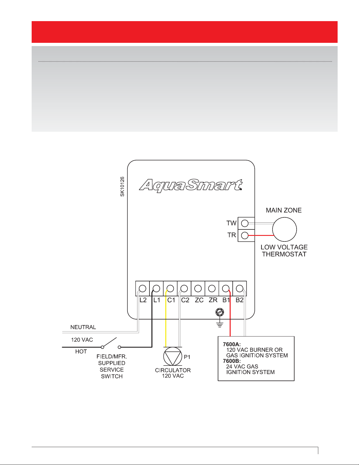
AquaSmart A or B single-zone connections
(with or without tankless H/W coil)
Control Programming - for optimal energy savings
1. High Limit: 180
2. High Differential: 10
3. Low Limit: “OFF”
4. Low Limit: 160 (with tankless H/W coil)
5. Low Differential: 10
6. Set DHWP to “OFF”
7. Set Circulator on “TT”
8. Circulator On-Delay: 30 Seconds
9. Circulator Off-Delay: 4 Minutes
10. Set Economizer to “ON”
11. Set Effi ciency “HI”
AquaSmart Boiler Control Wiring Guide
5
Page 6
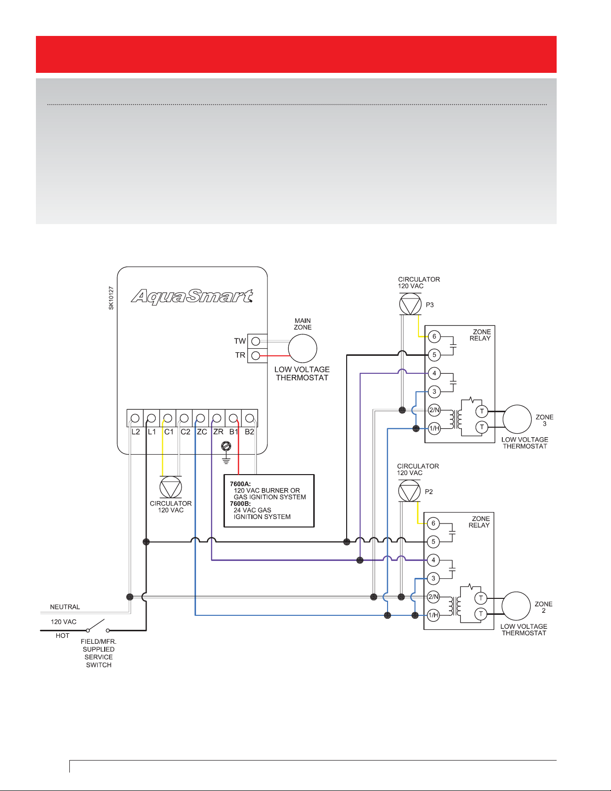
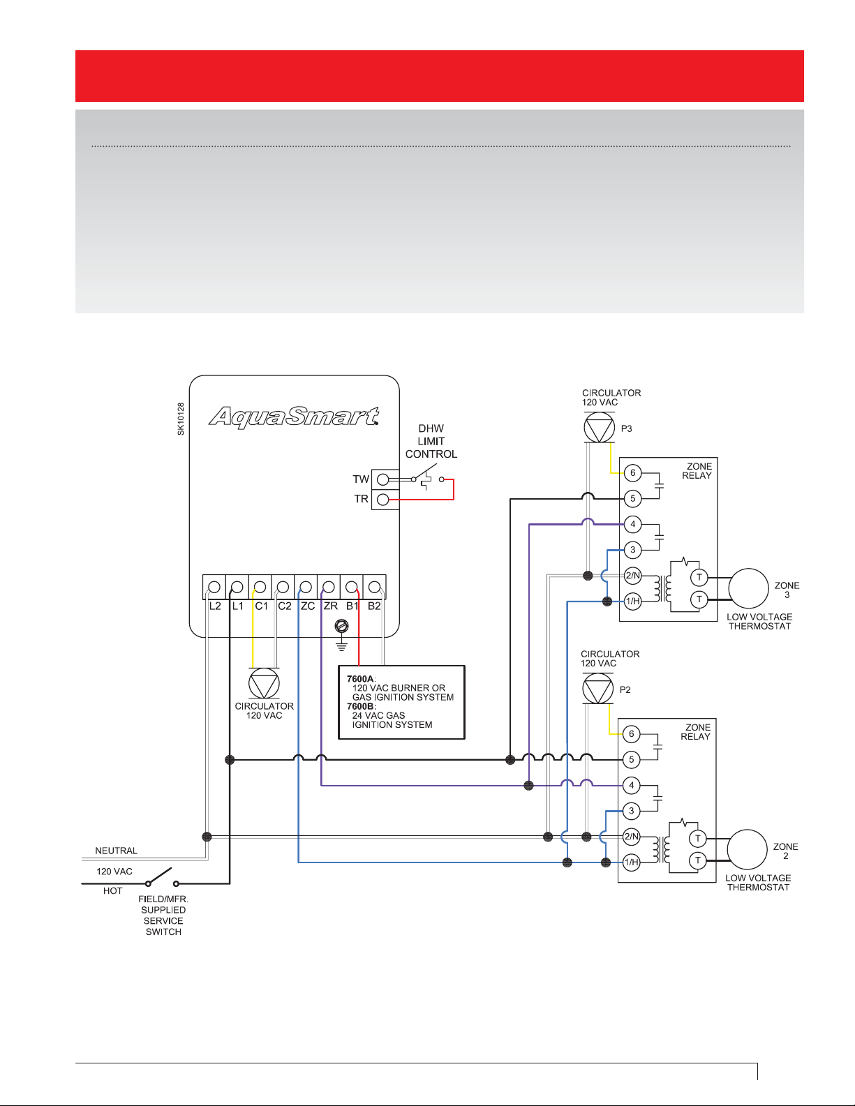
AquaSmart A or B multi-zone connections with main zone circulator
(with or without tankless H/W coil)
Control Programming - for optimal energy savings
1. High Limit: 180
2. High Differential: 10
3. Low Limit: “OFF”
4. Low Limit: 160 (with tankless H/W coil)
5. Low Differential: 10
6. Set DHWP to “OFF”
7. Set Circulator on “TT”
8. Circulator On-Delay: “OFF”
9. Circulator Off-Delay: 4 Minutes
10. Set Economizer to “ON”
11. Set Effi ciency “HI”
6
Technology Made Simple.
Page 7
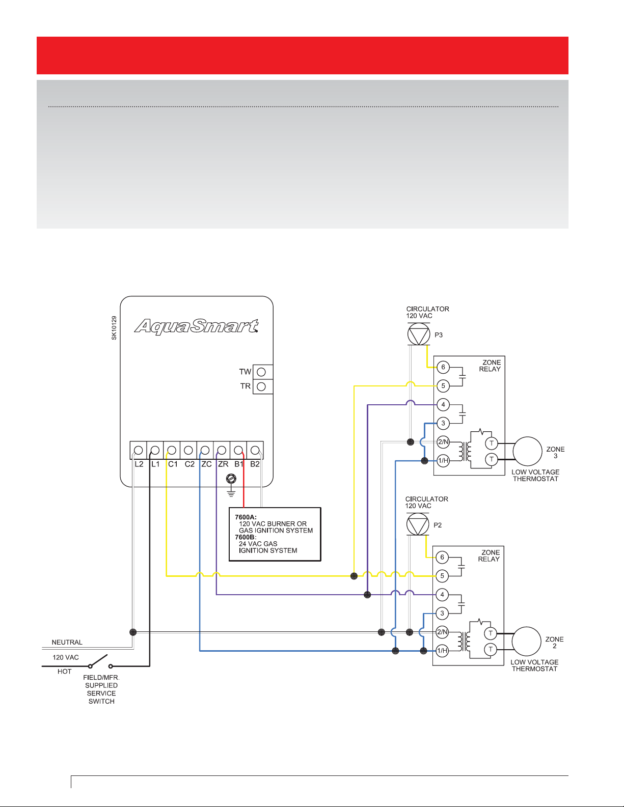
AquaSmart A or B multi-zone connections with indirect H/W circulator
Control Programming - for optimal energy savings
1. High Limit: 180
2. High Differential: 10
3. Low Limit: “OFF”
4. Set DHWP to “TT”
5. Set Circulator on “TT”
6. Circulator On-Delay: “OFF”
7. Circulator Off-Delay: 2 - 4 Minutes
8. Set Economizer to “ON”
9. Set Effi ciency “HI”
AquaSmart Boiler Control Wiring Guide
7
Page 8
AquaSmart A or B circulator on-delay on all zones
(with or without tankless H/W coil)
Control Programming - for optimal energy savings
1. High Limit: 180
2. High Differential: 10
3. Low Limit: “OFF”
4. Low Limit: 160 (with tankless H/W coil)
5. Low Differential: 10
6. Set DHWP to “OFF”
7. Set Circulator on “ZR”
8. Circulator On-Delay: As Needed
9. Circulator Off-Delay: “OFF”
10. Set Economizer to “ON”
11. Set Effi ciency “HI”
8
Technology Made Simple.
Page 9

Section II: Zone Valves
SPECIAL NOTICE: All temperature designations in this guide are degrees Fahrenheit (°F).
• Use the temperatures shown in the examples for typical reference only.
• Always follow the appliance manufacturer’s instructions regarding temperature settings.
AquaSmart Boiler Control Wiring Guide
9
Page 10
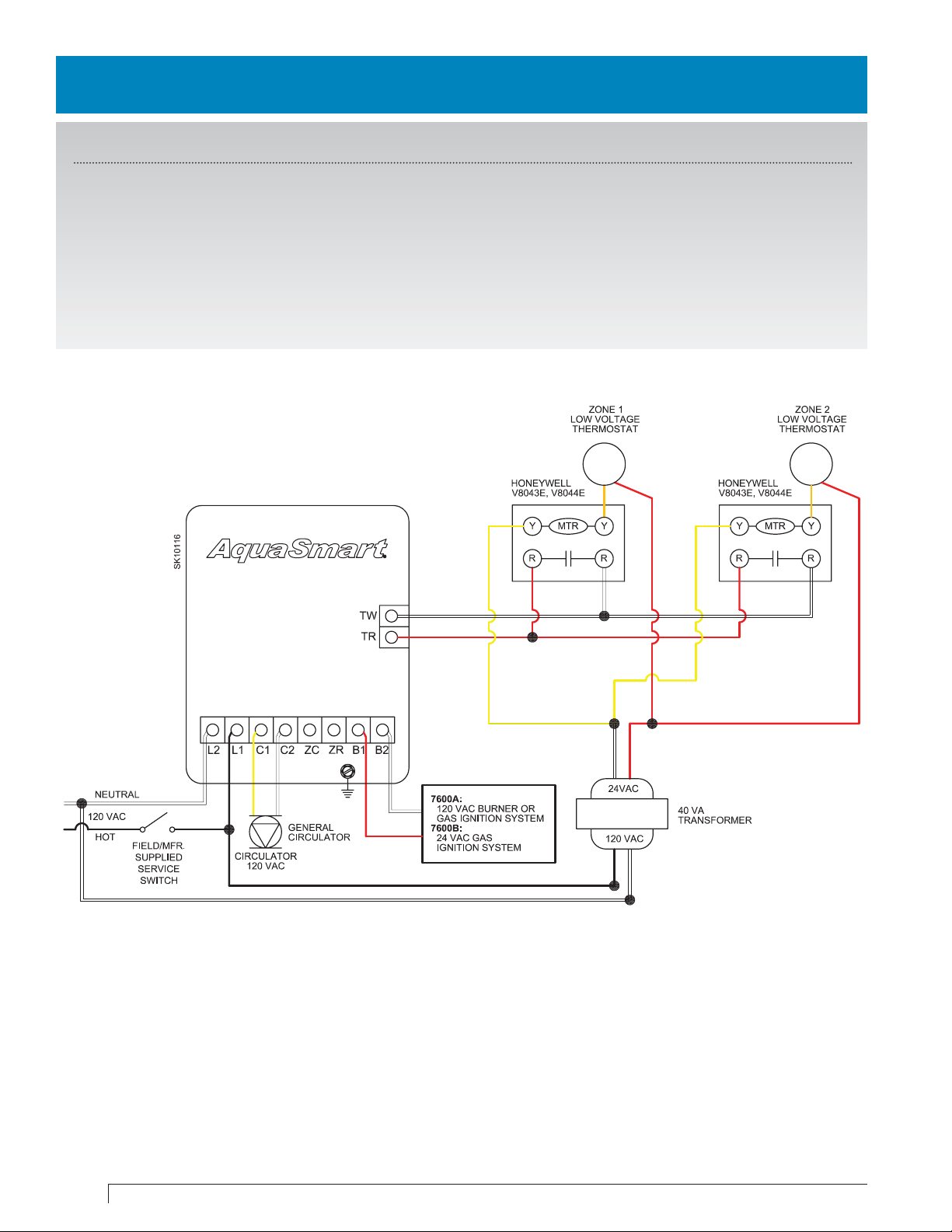
AquaSmart A or B with Honeywell V8043E/V8044E zone valves
(with or without tankless H/W coil)
Control Programming - for optimal energy savings
1. High Limit: 180
2. High Differential: 10
3. Low Limit: “OFF”
4. Set DHWP to “OFF”
5. Low Limit: 160 (with tankless H/W coil)
6. Low Differential: 10
7. Set Circulator on “TT”
8. Circulator On-Delay: 30 Seconds
9. Circulator Off-Delay: “OFF”
10. Set Economizer to “ON”
11. Set Effi ciency “HI”
10
Technology Made Simple.
Page 11
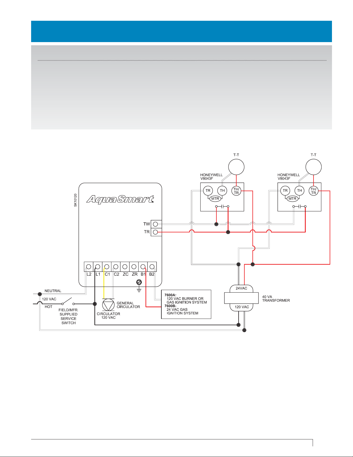
AquaSmart A or B with Honeywell V8043F zone valves
(with or without tankless H/W coil)
Control Programming - for optimal energy savings
1. High Limit: 180
2. High Differential: 10
3. Low Limit: “OFF”
4. Set DHWP to “OFF”
5. Low Limit: 160 (with tankless H/W coil)
6. Low Differential: 10
7. Set Circulator on “TT”
8. Circulator On-Delay: 30 Seconds
9. Circulator Off-Delay: “OFF”
10. Set Economizer to “ON”
11. Set Effi ciency “HI”
AquaSmart Boiler Control Wiring Guide
11
Page 12
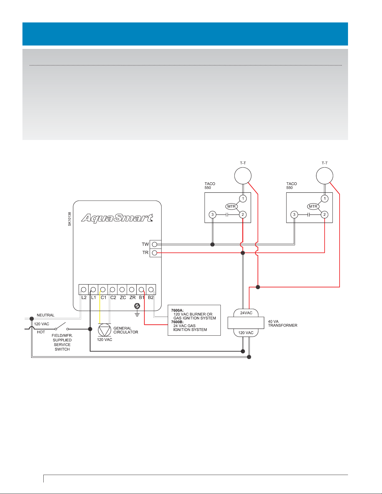
AquaSmart A or B with Taco 550 zone valves
(with or without tankless H/W coil)
Control Programming - for optimal energy savings
1. High Limit: 180
2. High Differential: 10
3. Low Limit: “OFF”
4. Set DHWP to “OFF”
5. Low Limit: 160 (with tankless H/W coil)
6. Low Differential: 10
7. Set Circulator on “TT”
8. Circulator On-Delay: 30 Seconds
9. Circulator Off-Delay: “OFF”
10. Set Economizer to “ON”
11. Set Effi ciency “HI”
12
Technology Made Simple.
Page 13
AquaSmart A or B with Honeywell V8043E/V8044E zone valves & main zone circulator
(with or without tankless H/W coil)
Control Programming - for optimal energy savings
1. High Limit: 180
2. High Differential: 10
3. Low Limit: “OFF”
4. Set DHWP to “OFF”
5. Low Limit: 160 (with tankless H/W coil)
6. Low Differential: 10
7. Set Circulator on “TT”
8. Circulator On-Delay: “30 Seconds”
9. Circulator Off-Delay: 4 minutes
10. Set Economizer to “ON”
11. Set Effi ciency “HI”
AquaSmart Boiler Control Wiring Guide
13
Page 14
AquaSmart A or B with Honeywell V8043E/V8044E zone valves & indirect H/W
circulator
Control Programming - for optimal energy savings
1. High Limit: 180
2. High Differential: 10
3. Low Limit: “OFF
4. Set DHWP to “TT”
5. Set Circulator on “TT”
6. Circulator On-Delay: “OFF”
7. Circulator Off-Delay: 2 - 4 Minutes
8. Set Economizer to “ON”
9. Set Effi ciency “HI”
14
Technology Made Simple.
Page 15
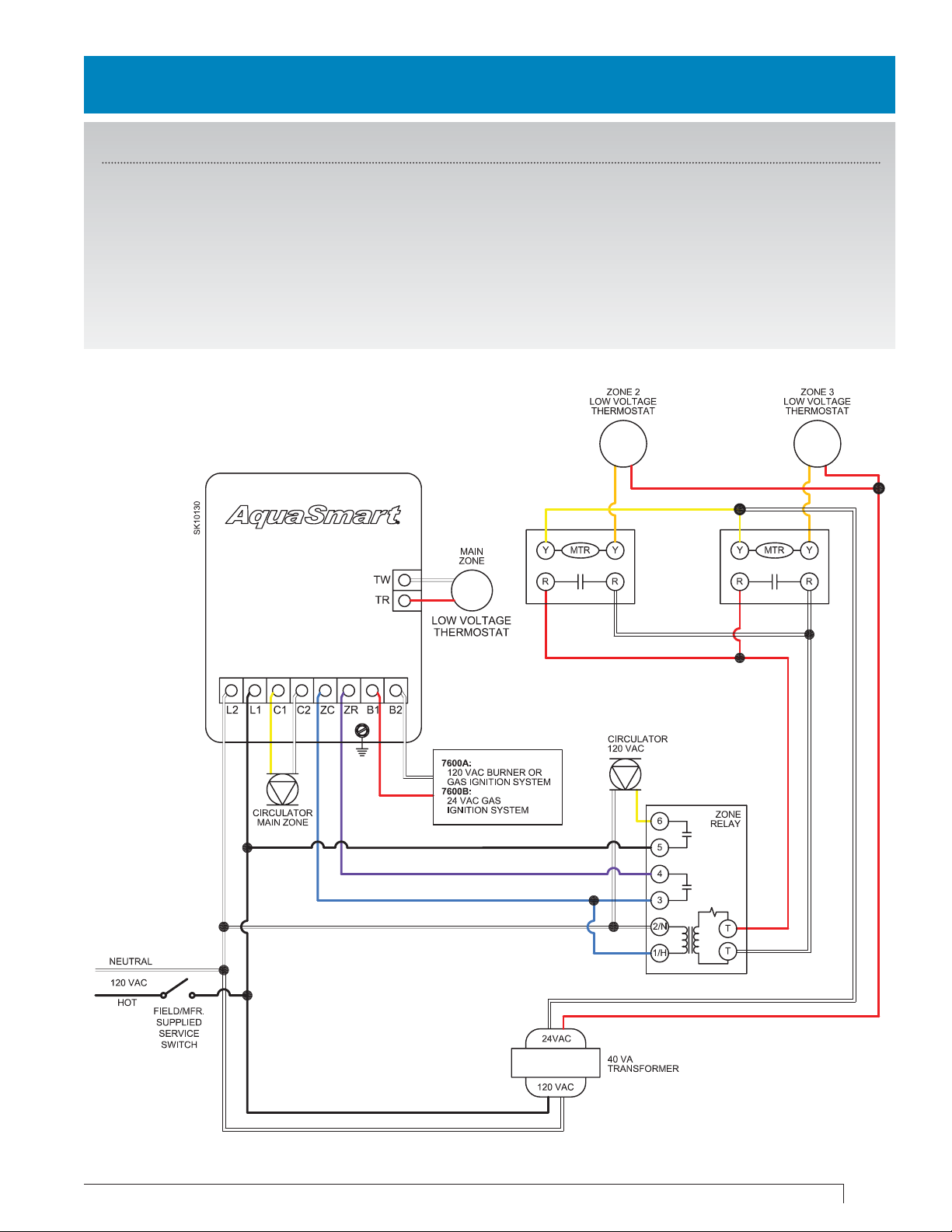
AquaSmart A or B with Taco 550 zone valves & main zone circulator
(with or without tankless H/W coil)
Control Programming - for optimal energy savings
1. High Limit: 180
2. High Differential: 10
3. Low Limit: “OFF”
4. Set DHWP to “OFF”
5. Low Limit: 160 (with tankless H/W coil)
6. Low Differential: 10
7. Set Circulator on “TT”
8. Circulator On-Delay: 30 Seconds
9. Circulator Off-Delay: 4 Minutes
10. Set Economizer to “ON”
11. Set Effi ciency “HI”
AquaSmart Boiler Control Wiring Guide
15
Page 16

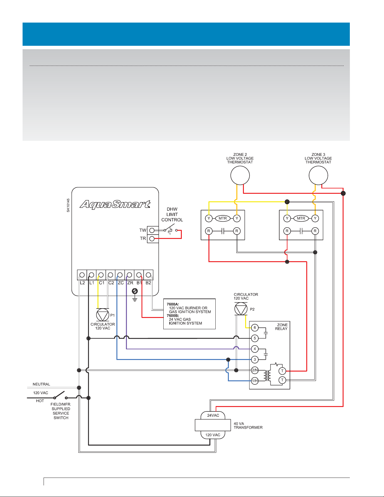
AquaSmart A or B with Taco 550 zone valves & indirect H/W circulator
Control Programming - for optimal energy savings
1. High Limit: 180
2. High Differential: 10
3. Low Limit: “OFF”
4. Set DHWP to “TT”
5. Set Circulator on “TT”
6. Circulator On-Delay: “OFF”
7. Circulator Off-Delay: 2 - 4 Minutes
8. Set Economizer to “ON”
9. Set Effi ciency “HI”
16
Technology Made Simple.
Page 17

AquaSmart A or B with Honeywell V8043F & main zone circulator
(with or without tankless H/W coil)
Control Programming - for optimal energy savings
1. High Limit: 180
2. High Differential: 10
3. Low Limit: “OFF”
4. Set DHWP to “OFF”
5. Low Limit: 160 (with tankless H/W coil)
6. Low Differential: 10
7. Set Circulator on “TT”
8. Circulator On-Delay: “OFF”
9. Circulator Off-Delay: 2 - 4 Minutes
10. Set Economizer to “ON”
11. Set Effi ciency “HI”
AquaSmart Boiler Control Wiring Guide
17
Page 18

AquaSmart A or B with Honeywell V8043F zone valves & indirect H/W circulator
Control Programming - for optimal energy savings
1. High Limit: 180
2. High Differential: 10
3. Low Limit: “OFF”
4. Set DHWP to “TT”
5. Set Circulator on “TT”
6. Circulator On-Delay: “OFF”
7. Circulator Off-Delay: 2 - 4 Minutes
8. Set Economizer to “ON”
9. Set Effi ciency “HI”
18
Technology Made Simple.
Page 19

AquaSmart A or B with Honeywell V8043E/8044E zone valves with indirect H/W
wired as priority
Control Programming - for optimal energy savings
1. High Limit: 180
2. High Differential: 10
3. Low Limit: “OFF”
4. Set DHWP to “ZR”
5. Set Circulator on “BOTH”
6. Circulator On-Delay: “OFF”
7. Circulator Off-Delay: “OFF”
8. Set Economizer to “ON”
9. Set Effi ciency “HI”
AquaSmart Boiler Control Wiring Guide
19
Page 20

AquaSmart A or B with Honeywell V8043F zone valves with indirect H/W wired as
priority
Control Programming - for optimal energy savings
1. High Limit: 180
2. High Differential: 10
3. Low Limit: “OFF”
4. Set DHWP to “ZR”
5. Set Circulator on “BOTH”
6. Circulator On-Delay: “OFF”
7. Circulator Off-Delay: “OFF”
8. Set Economizer to “ON”
9. Set Effi ciency “HI”
20
Technology Made Simple.
Page 21

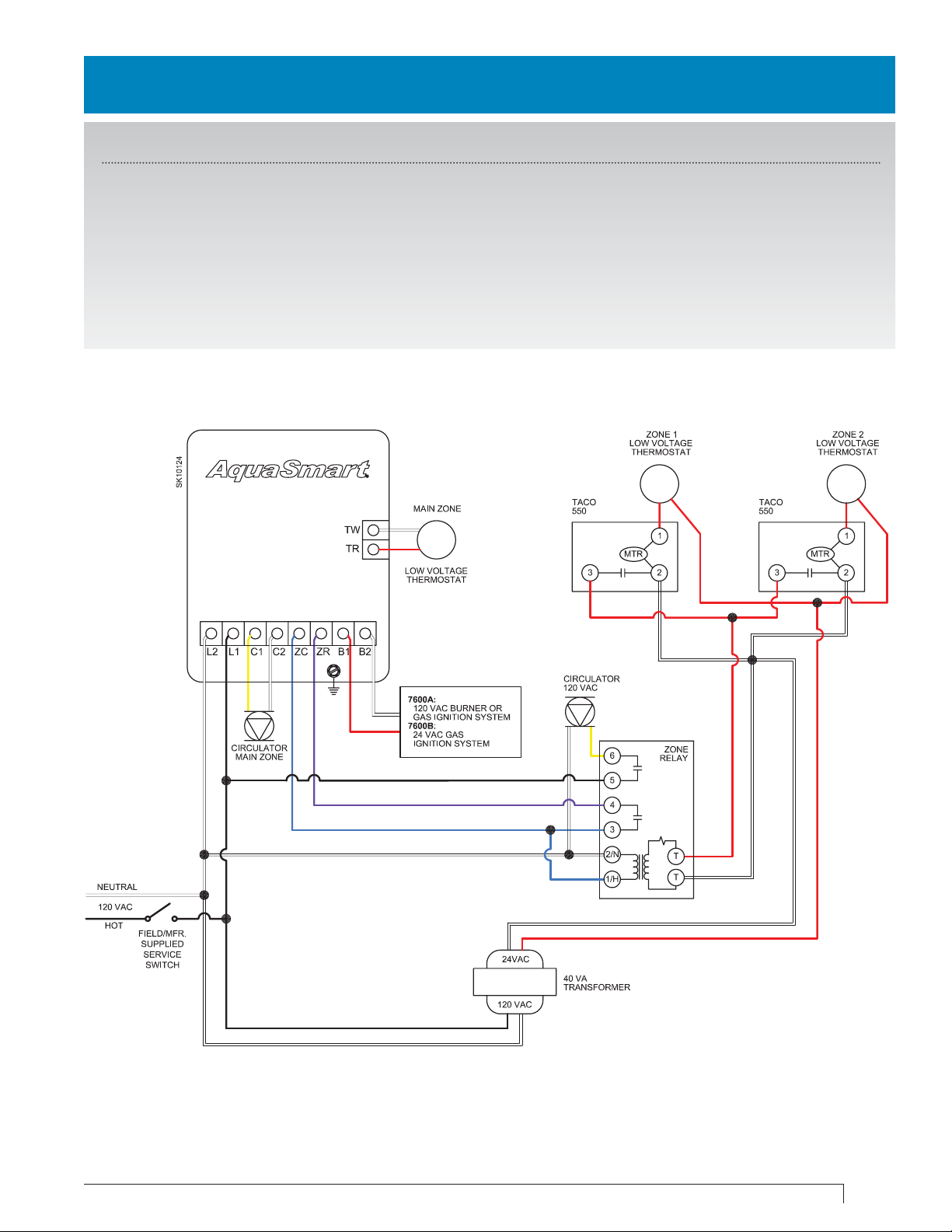
AquaSmart A or B with Taco 550 zone valves with indirect H/W wired as priority
Control Programming - for optimal energy savings
1. High Limit: 180
2. High Differential: 10
3. Low Limit: “OFF”
4. Set DHWP to “ZR”
5. Set Circulator on “BOTH”
6. Circulator On-Delay: “OFF”
7. Circulator Off-Delay: “OFF”
8. Set Economizer to “ON”
9. Set Effi ciency “HI”
AquaSmart Boiler Control Wiring Guide
21
Page 22

AquaSmart B only. Zone valves powered with 7600B. Circulator on-delay on all
valves.
Control Programming - for optimal energy savings
1. High Limit: 180
2. High Differential: 10
3. Low Limit: “OFF”
4. Set DHWP to “OFF”
5. Set Circulator on “TT”
6. Circulator On-Delay: “30 Seconds”
7. Circulator Off-Delay: “OFF”
8. Set Economizer to “ON”
9. Set Effi ciency “HI”
22
Technology Made Simple.
Page 23

Section III: Zone Panels
SPECIAL NOTICE: All temperature designations in this guide are degrees Fahrenheit (°F).
• Use the temperatures shown in the examples for typical reference only.
• Always follow the appliance manufacturer’s instructions regarding temperature settings.
AquaSmart Boiler Control Wiring Guide
23
Page 24

AquaSmart A or B Taco SR503 zone panel & indirect H/W circulator
Control Programming - for optimal energy savings
1. High Limit: 180
2. High Differential: 10
3. Set DHWP to “TT”
4. Set Circulator on “TT”
5. Circulator On-Delay: “OFF”
6. Circulator Off-Delay: 2 - 4 Minutes
7. Set Economizer to “ON”
8. Set Effi ciency “HI”
24
Technology Made Simple.
Page 25

AquaSmart A or B with Taco SR503 zone panel & main zone circulator
(with or without tankless H/W coil)
Control Programming - for optimal energy savings
1. High Limit: 180
2. High Differential: 10
3. Low Limit: “OFF”
4. Low Limit: 160 (with tankless H/W coil)
5. Low Differential: 10
6. Set DHWP to “OFF”
7. Set Circulator on “TT”
8. Circulator On-Delay: 30 Seconds
9. Circulator Off-Delay: 4 Minutes
10. Set Effi ciency “HI”
AquaSmart Boiler Control Wiring Guide
25
Page 26

AquaSmart A or B with Taco SR504 zone panel
(without tankless H/W coil)
Control Programming - for optimal energy savings
1. High Limit: 180
2. High Differential: 10
3. Low Limit: “OFF”
4. Low Limit: 160 (with tankless H/W coil)
5. Low Differential: 10
6. Set DHWP to “OFF”
7. Set Circulator on “TT”
8. Circulator On-Delay: “OFF”
9. Circulator Off-Delay: “OFF”
10. Set Economizer to “ON”
11. Set Effi ciency “HI”
Note: If tankless H/W coil installed, run wire between ZC terminals on AquaSmart & Zone Panel and set low
limit to 160°
26
Technology Made Simple.
Page 27

AquaSmart A or B with Taco SR504 zone panel & indirect H/W circulator
Control Programming - for optimal energy savings
1. High Limit: 180
2. High Differential: 10
3. Low Limit: “OFF”
4. Set DHWP to “TT”
5. Set Circulator on “TT”
6. Circulator On-Delay: “OFF”
7. Circulator Off-Delay: 2 - 4 Minutes
8. Set Economizer to “ON”
9. Set Effi ciency “HI”
AquaSmart Boiler Control Wiring Guide
27
Page 28

AquaSmart A or B with Taco ZVC406 zone valve wiring panel
(without tankless H/W coil)
Control Programming - for optimal energy savings
1. High Limit: 180
2. High Differential: 10
3. Low Limit: “OFF”
4. Low Limit: 160 (with tankless H/W coil)
5. Low Differential: 10
6. Set DHWP to “OFF”
7. Set Circulator on “TT”
8. Circulator On-Delay: 30 Seconds
9. Circulator Off-Delay: “OFF”
10. Set Economizer to “ON”
11. Set Effi ciency “HI”
28
Technology Made Simple.
Page 29

AquaSmart A or B with Taco ZVC406 zone valve wiring panel & indirect H/W
circulator
Control Programming - for optimal energy savings
1. High Limit: 180
2. High Differential: 10
3. Low Limit: “OFF”
4. Set DHWP to “TT”
5. Set Circulator on “TT”
6. Circulator On-Delay: “OFF”
7. Circulator Off-Delay: 2 - 4 Minutes
8. Set Economizer to “ON”
9. Set Effi ciency “HI”
AquaSmart Boiler Control Wiring Guide
29
Page 30

AquaSmart A or B with Argo 861 zone panel
(without tankless H/W coil)
Control Programming - for optimal energy savings
1. High Limit: 180
2. High Differential: 10
3. Low Limit: “OFF”
4. Low Limit: 160 (with tankless H/W coil)
5. Low Differential: 10
6. Set DHWP to “OFF”
7. Set Circulator on “TT”
8. Circulator On-Delay: “OFF”
9. Circulator Off-Delay: “OFF”
10. Set Economizer to “ON”
11. Set Effi ciency “HI”
30
Technology Made Simple.
Page 31

AquaSmart A or B with Argo 861 zone panel & main zone circulator
(with or without tankless H/W coil)
Control Programming - for optimal energy savings
1. High Limit: 180
2. High Differential: 10
3. Low Limit: “OFF”
4. Low Limit: 160 (with tankless H/W coil)
5. Low Differential: 10
6. Set DHWP to “OFF”
7. Set Circulator on “TT”
8. Circulator On-Delay: 30 Seconds
9. Circulator Off-Delay: 4 Minutes
10. Set Economizer to “ON”
11. Set Effi ciency “HI”
AquaSmart Boiler Control Wiring Guide
31
Page 32

AquaSmart A or B with Argo 861 zone panel & indirect H/W circulator
Control Programming - for optimal energy savings
1. High Limit: 180
2. High Differential: 10
3. Low Limit: “OFF”
4. Set DHWP to “TT”
5. Set Circulator on “TT”
6. Circulator On-Delay: “OFF”
7. Circulator Off-Delay: 2 - 4 Minutes
8. Set Economizer to “ON”
9. Set Effi ciency “HI”
32
Technology Made Simple.
Page 33

AquaSmart A or B with Taco HAFC101 Hydro-Air wiring panel
Control Programming - for optimal energy savings
1. High Limit: 180
2. High Differential: 10
3. Low Limit: “OFF”
4. Set DHWP to “OFF”
5. Set Circulator on “TT”
6. Circulator On-Delay: 30 Seconds
7. Circulator Off-Delay: 4 Minutes
8. Set Economizer to “ON”
9. Set Effi ciency “HI”
*Aquastat is a registered trademark of Honeywell International, Inc.
AquaSmart Boiler Control Wiring Guide
33
Page 34

Section IV: Install AquaSmart with Line Voltage
Thermostat
34
SPECIAL NOTICE: All temperaure designations in this guide are degrees Fahrenheit (°F).
• Use the temperatures shown in the examples for typical reference only.
• Always follow the appliance manufacturer’s instructions regarding temperature settings.
Technology Made Simple.
Page 35

AquaSmart A or B with line voltage thermostat
(with or without tankless H/W coil)
Control Programming - for optimal energy savings
1. High Limit: 180
2. High Differential: 10
3. Low Limit: “OFF”
4. Low Limit: 160 (with tankless H/W coil)
5. Low Differential: 10
6. Set DHWP to “OFF”
7. Set Circulator on “TT”
8. Circulator On-Delay: “OFF”
9. Circulator Off-Delay: “OFF”
10. Set Economizer to “ON”
11. Set Effi ciency “HI”
AquaSmart Boiler Control Wiring Guide
35
Page 36

AquaSmart A or B with line voltage thermostat & indirect H/W circulator
Control Programming - for optimal energy savings
1. High Limit: 180
2. High Differential: 10
3. Low Limit: “OFF”
4. Set DHWP to “TT”
5. Set Circulator on “TT”
6. Circulator On-Delay: “OFF”
7. Circulator Off-Delay: 2 - 4 Minutes
8. Set Economizer to “ON”
9. Set Effi ciency “HI”
36
Technology Made Simple.
Page 37

Section V: Direct Replacement of Honeywell
Aquastat
*Aquastat is a registered trademark of Honeywell International, Inc.
®
Relays to Beckett AquaSmart
®
SPECIAL NOTICE: All temperature designations in this guide are degrees Fahrenheit (°F).
• Use the temperatures shown in the examples for typical reference only.
• Always follow the appliance manufacturer’s instructions regarding temperature settings.
AquaSmart Boiler Control Wiring Guide
37
Page 38

AquaSmart B only. Single zone connections to replace with millivolt gas valve
Control Programming - for optimal energy savings
1. High Limit: 180
2. High Differential: 10
3. Low Limit: “OFF”
4. Low Limit: 160 (with tankless H/W coil)
5. Low Differential: 10
6. DHWP: “OFF”Set Circulator on “TT”
7. Circulator On-Delay: 30 Seconds
8. Circulator Off-Delay: 4 Minutes
9. Set Economizer to “ON”
10. Set Effi ciency “HI”
38
Technology Made Simple.
Page 39

AquaSmart A only. Single-zone replacement for Honeywell R8182H
Control Programming - for optimal energy savings
1. High Limit: 180
2. High Differential: 10
3. Low Limit: “OFF
4. Set DHWP to “OFF”
5. Low Limit: 160 (with tankless H/W coil)
6. Low Differential: 10
7. Set Circulator on “TT”
8. Circulator On-Delay: 30 Seconds
9. Circulator Off-Delay: 4 Minutes
10. Set Economizer to “ON”
11. Set effi ciency “HI”
AquaSmart Boiler Control Wiring Guide
39
Page 40

Direct Replacement of Honeywell L8148A with AquaSmart A
9
Legend
3
1 - Neutral / White
4
2 - Hot / From Low Water Cut Off
3 - Red / To Thermostat
2
1
4 - White / To Thermostat
5 - Hot / To Circulator
6 - Neutral / To Circulator
7 - Hot / To Burner Ignition
8 - Neutral / To Burner Ignition
9 - Ground
Notes on AquaSmart:
5
6
7
8
1. Terminals ZC and ZR are not used in this
application.
2. If using the 2-in-1 probe, the hot to L1 will be
supplied from Service Switch. Also remove
current Low Water Cut Off.
AquaSmart Settings:
• High Limit: 180
• High Differential: 10
• Low Limit: “OFF”
• Set DHWP to “OFF”
4
• Set Circulator on “TT”
• Circulator On-Delay: 30 Seconds
3
• Circulator Off-Delay: 4 Minutes
5
68
72
• Set Economizer to “ON”
• Set Effi ciency “HI”
1
9
40
Technology Made Simple.
Page 41

Direct Replacement of Honeywell L8124A with AquaSmart A
9
Legend
3
4
2
1
1 - Neutral / White
2 - Hot / From Low Water Cut Off
3 - Red / To Thermostat
4 - White / To Thermostat
5 - Hot / To Circulator
6 - Neutral / To Circulator
7 - Hot / To Burner Ignition
8 - Neutral / To Burner Ignition
9 - Ground
5
Notes on AquaSmart:
1. Terminals ZC and ZR are not used in this
8
67
application.
2. If using the 2-in-1 probe, the hot to L1 will be
supplied from Service Switch. Also remove
current Low Water Cut Off.
AquaSmart Settings:
• High Limit: 180
• High Differential: 10
• Low Limit: “OFF”
• Set DHWP to “OFF”
4
3
5
68
72
• Low Limit: 160 (with Tankless H/W Coil)
• Low Differential: 10
• Set Circulator on “TT”
• Circulator On-Delay: 30 Seconds
• Circulator Off-Delay: 4 Minutes
• Set Economizer to “ON”
• Set Effi ciency “HI”
1
9
AquaSmart Boiler Control Wiring Guide
41
Page 42

Direct Replacement of Honeywell L7224U with AquaSmart A
Legend
9
2
3
4
1
1 - Neutral / White
2 - Hot / From Low Water Cut Off
3 - Red / To Thermostat
4 - White / To Thermostat
5 - Hot / To Circulator
6 - Neutral / To Circulator
7 - Hot / To Burner Ignition
8 - Neutral / To Burner Ignition
9 - Ground
6
8
5
7
Notes on AquaSmart:
1. Set control to match determined High Limit or
Low Limit application.
2. Terminals ZC and ZR are not used in this
application.
3. If using the 2-in-1 probe, the hot to L1 will be
supplied from Service Switch. Also remove
current Low Water Cut Off
.
42
AquaSmart Settings:
• High Limit: 180
• High Differential: 10
4
3
5
68
72
1
• Low Limit: “OFF”
• Set DHWP to “OFF”
• Low Limit: 160 (with Tankless H/W Coil)
• Low Differential: 10
• Set Circulator on “TT”
• Circulator On-Delay: 30 Seconds
• Circulator Off-Delay: 4 Minutes
• Set Economizer to “ON”
• Set Effi ciency “HI”
9
Technology Made Simple.
Page 43

Direct Replacement of Honeywell L8182D with AquaSmart A & GeniSys 7505A
2
1
Legend
3
1 - Neutral / White
4
2 - Hot / From Low Water Cut Off
3 - Red / To Thermostat
4 - White / To Thermostat
5 - Hot / To Circulator
6 - Neutral / To Circulator
7 - Hot / To Burner Ignition
8 - Neutral / To Burner Ignition
9 - Ground
7
Notes on AquaSmart:
6
1. Must add a primary control to the burner.
8
9
(Example: GeniSys 7505A).
2. Terminals ZC and ZR are not used in this
application.
3. If using the 2-in-1 probe, the hot to L1 will be
supplied from Service Switch. Also remove
current Low Water Cut Off
.
AquaSmart Settings:
• High Limit: 180
• High Differential: 10
4
3
5
68
72
1
• Low Limit: “OFF”
• Set DHWP to “OFF”
• Low Limit: 160 (with Tankless H/W Coil)
• Low Differential: 10
• Set Circulator on “TT”
• Circulator On-Delay: 30 Seconds
• Circulator Off-Delay: 4 Minutes
• Set Economizer to “ON”
• Set Effi ciency “HI”
9
AquaSmart Boiler Control Wiring Guide
43
Page 44

RIB (Relay In a Box)
Description:
Enclosed Relay 10 Amp SPDT with
10-30 VAC/dc/120Volt Coil
Specifi cations:
• Coil Voltage - AC/DC 10-30
• Coil Voltage - AC 120V
• Contact Rating - Motor 1/3HP
• Contact Rating - Ballast 480 VA
• Contact Rating - Tungsten 600W
• Contact Rating - Pilot Duty 480VA
• Gold Flash - Yes
• Override Switch - No
44
Technology Made Simple.
Page 45

Section IV - Cross-Reference Guide
AquaSmart Boiler Control Wiring Guide
45
Page 46

AquaSmart Cross-Reference Guide - Direct Replacements
Table 1 - Direct Replacements
Honeywell
L8124A (All) L8124C (All)
L7124A (All)
L7124C (All)
L7148A (All)
L7224A (All)
L8148A (All)
L8124E 1016 L8148E 1265
L8124M (All)
L8151A
L7224C (All)
L7224U (All)
L7248A (All)
L7248C (All)
Hydrolevel
3100
3150
Replace with AquaSmart 7600A
7600 outputs are not rated for 240 VAC.
Replace with AquaSmart 7600A
The 7600 has no Honeywell EnviraCOMTM Communications port. The diagnostic LED lights are replaced by the
7600’s display.
Replace with AquaSmart 7600A
7600 outputs are not rated for 240 VAC. B1 terminal on 7600 utilizes a 1/4” quick connect. Set low limit on 7600
to OFF.
Replace with AquaSmart 7600B
7600 outputs are not rated for 240 VAC. B2, TW and TR terminals replace TV, T and Z, respectively.
Replace with AquaSmart 7600A
For replacement with the 7600: Turn low limit off so the circulator is controlled directly by the thermostat and ZC is
constantly powered.
Replace with AquaSmart 7600A
7600 outputs are not rated for 240 VAC. Remote mount sensor cable needed (Part No. 52120)
Replace with AquaSmart 7600B
Not a suitable replacement if Low Water Cutoff (LWCO) functionality is used.
Replace with AquaSmart 7600A
Not a suitable replacement if Low Water Cutoff (LWCO) functionality is used.
Carlin
90524A
Replace with AquaSmart 7600A
Make sure 7600 outputs do not exceed 7.4A. Available operating limit and differential ranges are not equivalent.
White Rodgers
11C15-11 Replace with AquaSmart 7600A
11C30-3 11B54-4
8B48A-217
11C61-12
8F48A-351 8B43A-601 Replace with AquaSmart 7600B
Make sure 7600 outputs do not exceed 7.4A @ 120 VAC. 7600 outputs are not rated for 240 VAC.
Available operating limit and differential ranges may not be equivalent.
Replace with AquaSmart 7600A
Replace with AquaSmart 7600A
Not a suitable replacement if SPDT switch action is required; only break-on-rise available on 7600.
Make sure 7600 outputs do not exceed 7.4A @ 120 VAC. 7600 outputs are not rated for 240 VAC.
Functional replacements on next page ►
46
Technology Made Simple.
Page 47

AquaSmart Cross-Reference Guide - Functional Replacements
Table 2 - Functional Replacement (Advanced Wiring Needed)
Note: Available operating limit and/or differential ranges may not be equivalent. Compare settings to the AquaSmart
ranges before replacing.
Honeywell
L4006A (All)
L4006G 1022
L4006H 1004
L4008A (All)
L4080B,D
Replace with AquaSmart 7600A or 7600B
Make sure 7600 outputs do not exceed 7.4A @ 120 VAC. 7600 outputs are not rated for 240 VAC.
operation.
Short TW-TR terminals. C1, C2, ZC, and ZR are unused. ●
appropriate voltage relay with isolated gold plated contacts must be added to switch the millivolt circuit.
(Based on System Voltage Requirements)
Set low limit on 7600 to OFF.
●
7600 will require an additional wire (L2) for
●
To use with a millivolt system an
L4006E (All)
L4008E (All)
L4080F,G
L6006A (All)
L6006C 1018
L6008A 1192
L6008A 1242
L8124B 1039
L8148J 1009
L7148F (All)
L8148E (All)
L4081A/B
L6081A/C
Carlin
90200A
90000 (All)
90200E
90200EL
90300B
Replace with AquaSmart 7600A or 7600B
Requires the addition of a manual-reset high limit. ●
are not rated for 240 VAC. ●
unused.
●
be added to switch the millivolt circuit.
Replace with AquaSmart 7600A or 7600B
Not a suitable replacement if SPDT switch action is required; only break-on-rise available on 7600.
voltage relay with isolated gold plated contacts must be added to switch the millivolt circuit.
VAC. 7600 outputs are not rated for 240 VAC.
and ZR are unused. ●
Replace with AquaSmart 7600A or 7600B
To use with a millivolt system an appropriate voltage relay with isolated gold plated contacts must be added to switch the millivolt circuit. 7600 outputs
are not rated for 240 VAC.
Replace with AquaSmart
Must confi rm that 7600 VA rating is adequate to meet VA requirements of system.
(30 VA).
damper manufacturer’s wiring instructions for using damper without damper plug.
Replace with AquaSmart 7600A or 7600B
Remove switching relay, if used, from the system when replacing the L4081 or L6081.
7600 outputs are not rated for 240 VAC.
Replace with AquaSmart 7600A or 7600B
Make sure 7600 outputs do not exceed 7.4A. Set low limit on 7600 to OFF.
Replace with AquaSmart 7600A or 7600B
Requires the addition of a manual-reset high limit. Make sure 7600 outputs do not exceed 7.4A.
Set low limit on 7600 to OFF. ●
●
7600 outputs are not rated for 240 VAC. B2, TW and TR terminals replace TV, T and Z, respectively.
7600 will require an additional wire (L2) for operation. Short TW-TR terminals. C1, C2, ZC, and ZR are
Set low limit on 7600 to OFF.
●
7600B
(Based on System Voltage Requirements)
Make sure 7600 outputs do not exceed 7.4A @ 120VAC. ●
To use with a millivolt system an appropriate voltage relay with isolated gold plated contacts must
(Based on System Voltage Requirements)
7600 will require an additional wire (L2) for operation.
(Based on System Voltage Requirements)
●
Make sure 7600 B1 output does not exceed 1.25A @ 24VAC
(Based on System Voltage Requirements)
(Based on System Voltage Requirements)
(Based on System Voltage Requirements)
●
●
●
Make sure 7600 outputs do not exceed 7.4A@120VAC.
To use with a millivolt system an appropriate
Make sure 7600 outputs do not exceed 7.4A @ 120
Short TW-TR terminals. C1, C2, ZC,
●
●
Set low limit on 7600 to OFF.
7600 outputs
If damper is used, consult
90200D
White Rodgers
11B06-1
11D18-1
11B18-101
11B30-104
11B02-1
11D82-1
11D31-1
1131-102
11B27-9
8J48A-209
1145-33
11B06-46
11B95-31
11B18-153
1127-2
11A79-2
1127-9
Replace with AquaSmart 7600A or 7600B
Not a suitable replacement if SPDT switch action is required; only break-on-rise available on 7600. Make sure 7600 outputs do not exceed 7.4A.
Set low limit on 7600 to OFF.
Replace with AquaSmart 7600A or 7600B
Make sure 7600 outputs do not exceed 7.4A @ 120 VAC. 7600 outputs are not rated for 240 VAC. 7600 will require an additional wire (L2) for
operation.
Short TW-TR terminals. C1, C2, ZC, and ZR are unused. ●
Replace with AquaSmart 7600A or 7600B
Not a suitable replacement if SPDT switch action is required; only break-on-rise available on 7600. 7600 outputs are not rated for 240 VAC.
7600 will require an additional wire (L2) for operation.
OFF.
Replace with AquaSmart 7600A or 7600B
Requires the addition of a manual-reset high limit.
VAC. 7600 will require an additional wire (L2) for operation.
7600 to OFF.
Replace with AquaSmart 7600A or 7600B
To use with a millivolt system an appropriate voltage relay with isolated gold plated contacts must be added to switch the millivolt
circuit.
AquaSmart Boiler Control Wiring Guide
(Based on System Voltage Requirements)
(Based on System Voltage Requirements)
Set low limit on 7600 to OFF.
(Based on System Voltage Requirements)
Short TW-TR terminals. C1, C2, ZC, and ZR are unused. ●
(Based on System Voltage Requirements)
●
Make sure 7600 outputs do not exceed 7.4A @ 120 VAC. 7600 outputs are not rated for 240
Short TW-TR terminals. C1, C2, ZC, and ZR are unused. ●
(Based on System Voltage Requirements)
Set low limit on 7600 to
Set low limit on
●
47
Page 48

Limited Warranty Information
The R. W. BECKETT CORPORATION (“Beckett”) warrants to persons who purchase its “Products” from
Beckett for resale, or for incorporation into a product for resale (“Customers”), that its equipment is free
from defects in material and workmanship. To qualify for warranty benefi ts, products must be installed by a
qualifi ed service agency in full compliance with all codes and authorities having jurisdiction, and used within
the tolerances of Beckett’s defi ned product specifi cations.
To review the complete warranty policy and duration of coverage for a specifi c product, or obtain a written
copy of warranty form 61545, please choose one of the following options:
1. Visit our website at: www.beckettcorp.com/warranty
2. Email your request to: rwb-customer-service@beckettcorp.com
3. Write to: R. W. Beckett Corporation, P. O. Box 1289, Elyria, OH 44036
NOTE: Beckett is not responsible for any labor cost for removal and replacement of equipment.
THIS WARRANTY IS LIMITED TO THE PRECISE TERMS SET FORTH ABOVE, AND PROVIDES
EXCLUSIVE REMEDIES EXPRESSLY IN LIEU OF ALL OTHER REMEDIES, AND IN PARTICULAR
THERE SHALL BE EXCLUDED THE IMPLIED WARRANTIES OF MERCHANTABILITY AND FITNESS
FOR A PARTICULAR PURPOSE. IN NO EVENT WILL BECKETT BE LIABLE FOR ANY INCIDENTAL OR
CONSEQUENTIAL DAMAGE OF ANY NATURE. Beckett neither assumes, nor authorizes any person to
assume for Beckett, any other liability or obligation in connection with the sale of this equipment. Beckett’s
liability and Customer’s exclusive remedy is limited to the cost of the product.
USA: P.O. Box 1289
Canada: R.W. Beckett Canada, Ltd.
www.beckettcorp.com * 1-800-Oilburn (645-2876)
●
Elyria, Ohio 44036
●
Unit #3, 430 Laird Road ● Guelph, Ontario N1G 3X7
Part Number 61856 R00, Printed in the U.S.A. 02/12
 Loading...