

Page 1
CONFIDENTIAL INFORMATION
OF BASLER ELECTRIC COMPANY, HIGHLAND, IL.
IT IS LOANED FOR CONFIDENTIAL USE, SUBJECT
TO RETURN ON REQUEST, AND WITH THE
MUTUAL UNDERSTANDING THAT IT WILL NOT BE
USED IN ANY MANNER DETRIMENTAL TO THE
INTEREST OF BASLER ELECTRIC COMPANY.
INSTRUCTION MANUAL
FOR
VOLTAGE REGULATOR
Model: VR63-4B
Publication:
9 1668 00 996
© 1998, Basler Electric Co., Highland, IL 62249
First Printing August 1988
Revision: C January 1998
ECA: 16515
BASLER ELECTRIC, BOX 269, HIGHLAND, IL 62249 PHONE 618/654-2341 FAX 618/654-2351
WARNING
To prevent personal injury or equipment
damage, only qualified technicians or
operators should install, operate, or
service this devi ce.
ELECTRICAL SPECIFICATIONS
Dc Output Power:
4 Adc at 63 Vdc (252W) maximum
continuous,
7 Adc at 100 Vdc (700W) forcing one m i nut e
(at 240 Vac input).
Exciter Field Dc Resistance:
15 ohms minimum; 100 ohms m aximum.
Ac Power Input:
Operating range: 190 Vac to 240 Vac , +10%,
Single phase, 50/60 Hz +5%, Burden 500 VA.
Voltage Adjust Range:
171-264 Vac.
Regulation Accuracy:
Better than ±1.0% no load to ful l l oad.
Response Time:
Less than 1.5 cycles for +10% change in
sensing voltage.
EMI Suppression:
Internal electromagnetic interference filter
(EMI filter).
Overexcitation Shutdown:
Output power is removed under the foll owi ng
conditions: Exc i ter field voltage exceeds
100+5 Vdc for a time inversel y proportional to
voltage magnitude, or inst ant aneously if the
exciter field volt age exceeds 135+5 Vdc.
Voltage Build-up:
Internal provisions for aut omatic vol tage buil dup from generator residual voltages as low as
10 Vac.
Power Dissipation:
8 Watts maximum.
PHYSICAL SPECIFICATIONS
Operating Temperature:
-40° C (-40° F) to +60° C (+140° F).
Storage Temperature:
-65° C (-85° F) to +85° C (+185° F).
CSA Approved
FUSES
It is recommended that fuses with high
interruption capability be installed per the
interconnection diagram to prot ect wiring from
faults before the regulator. Refer to the
Interconnection Diagram.
NOTE
Fuse must be installed per the
interconnection diagrams t o avoid interrupting the field current.
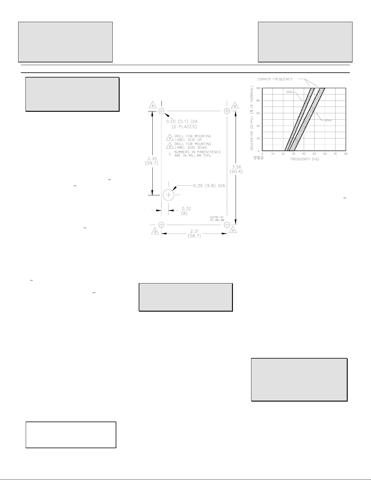
MOUNTING
The regulator may be mounted in any
position. Refer to the drilling diagrams.
Drilling Diagram
EXCITER FIELD P OWER CIRCUIT (wires F+
and F-).
Connect the regulator wire F+ to the brushl ess
exciter field terminal F+, and wi re F- to
terminal F-.
CAUTION
The dc resistance of the exciter field
must be equal to or greater than 15 ohm s
and less than 100 ohms.
POWER/SENSING INP UT CIRCUIT (wires 3
and 4)
Connect as shown by the Interconnection
Diagram.
UNDERFREQUENCY CHARACTERIS T IC
POINT
For 50 Hz systems, connect the Hz leads.
For 60 Hz systems, disconnect the Hz leads.
See curves the following figure.
Frequency Compensation Curves
OVEREXCITATION SHUT DOWN
This circuit removes the output power if the
exciter field volt age exceeds 100 ±5 Vdc aft er
a time delay. If the v oltage exceeds, 135 +5
Vdc, the output power is removed
instantaneously.
After shutdown, reset the regulator by
decreasing voltage below 6 Vac either by
stopping the prime mover or interrupting the
regulator input with a reset switch for 2
seconds or more.
VOLTAGE ADJUST
Screwdriver adjustable potentiometer adjusts
generator output voltage. Adjustment CW
increases voltage.
STABILITY ADJUST
Screwdriver adjustable (on non-label side)
potentiometer adjusts the stability and
response of the generator output voltage.
Adjustment CW increases the stability.
NOTE: Excessive CCW rotation of this
adjustment may result in osc illations (hunting)
of the generator output voltage.
OPERATION
The following system operation procedures
provide instructions f or adjusting t he VR63-4B
Voltage Regulator.
CAUTION
Meggers and high potential test
equipment must not be used. Incorrect
use of such equipment could dam age the
semiconductors contained in the
regulator.
PRELIMINARY SE T -UP
To prevent damage to the regulat or, compl ete
the following steps before proceeding with
system start-up.
a. Verify that the voltage regulator
specification conform s with the generator
system requirements.
Page 2
b. Ensure that the regulator is correctly
connected to the generator. See
Interconnection Diagram.
c. Install fuses per FUSES paragraph.
d. Set the regulator voltage control fully
CCW and the Stability Potentiometer to
mid-range.
SYSTEM START-UP
a. Start the prime mover and bring up to
rated speed. Voltage should buildup. If a
minimum residual of 10V is not present,
perform field flashing.
b. Slowly adjust volt age cont rol until voltage
reaches nominal value.
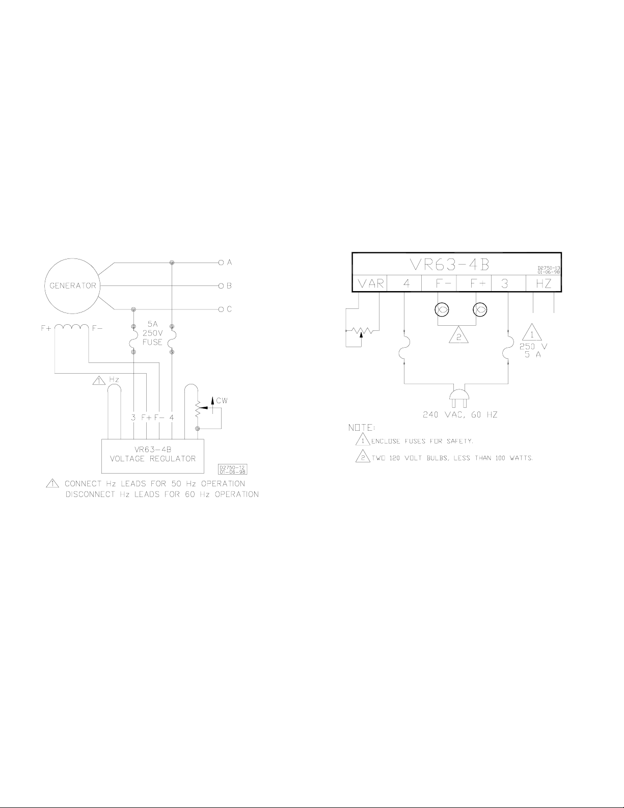
OPERATIONAL TEST
a. Connect the test setup as shown in
Operational Test. Do not apply power.
b. Adjust regulator voltage adjust to
maximum CCW.
c. Apply 240V, 60 Hz power to regulator.
RESULT: Light bulb flashes momentaril y.
d. Slowly adjust the regulat or voltage adjsut
CW.
RESULT:
1) Before the full CW position i s reached, the
light bulb reaches full brilliance to signify the
regulating point.
2) At the regulating point, a small change in
the voltage adjust should t urn the light bul b on
or off.
FIELD FLASHING
When the regulator is operated with the
generator for the first time, the polarity of
residual magnetism may not correct or the
magnitude not enough. If the generator does
not build-up after startup, shut down the prime
mover and proceed with the followi ng steps:
a. With the prime mover at rest , apply a dc
source (not grounded) of not more than
12V, to terminals F+(positive) and F-
(negative) in series with a limiting resistor
of 3-5 ohms.
b. Allow approximately 3 seconds before
removing the dc source.
c. Start prime mover and measure voltage
at regulator leads 3 and 4. If volt age is
greater than 10 volts, voltage build-up
should be successful. Repeat field
flashing procedure if less than 10 V
residual is measured.
d. If repeating steps 1 and 2 does not result
in generator voltage build-up, replace the
voltage regulator.
Interconnection Diagram, 208/240 V Nominal
Operational Test
 Loading...