

Page 1
INSTRUCTION MANUA L
FOR
RDP-110
Remote Display Panel
Publication: 9318100990
Revision: H 12/14
Page 2

Page 3

9318100990 Rev H i
Caution
Note
Preface
This instruction manual provides information about the installation and operation of the RDP-110 Remote
Display Panel. To accomplish this, the following information is provided:
• Product specifications
• Functional description
• Mounting and wiring
• Testing
Conventions Used in this Ma nua l
Important safety and procedural information is emphasized and presented in this manual through
warning, caution, and note boxes. Each type is illustrated and defined as follows.
Warning!
Warning boxes call attention to conditions or actions that may cause
personal injury or death.
Caution boxes call attention to operating conditions that may lead to
equipment or property damage.
Note boxes emphasize important information pertaining to Remote
Display Panel installation or operation.
Remote Display Panel Preface
Page 4
ii 9318100990 Rev H
Basler Electric does not assume any responsibility for compliance or noncompliance with national code, local
For terms of service relating to this product and software, see the Commercial Terms of Products and Services
document available at www.basler.com/terms.
This publication contains confi dent i al inform at ion of Basler Electric Company, an Illinois corporation. It is loaned for
and options are subject to modification without notice. Over time, improvements and revisions may be made to this
manual.
The English-language version of this manual serves as the only approved manual version.
12570 State Route 143
Highland IL 62249-1074 USA
www.basler.com
info@basler.com
Tel: +1 618.654.2341
Fax: +1 618.654.2351
© 2014 by Basler Electric
All rights reserved
First printing: June 1998
Warning!
READ THIS MANUAL. Read this manual before installing, operating, or maintaining the RDP-110.
Note all warnings, cautions, and notes in this manual as well as on the product. Keep this manual with
the product for reference. Failure to follow warning and cautionary labels may result in personal injury
or property damage. Exercise caution at all times.
To prevent personal injury or equipment damage, only qualified personnel should install, operate, or
service this system.
code, or any other applicable code. This manual serves as reference material that must be well understood prior to
installation, operation, or maintenance.
confidential use, subject to return on request, and with the mutual understanding that it will not be used in any
manner detrimental to the interests of Basler Electric Company and used strictly for the purpose intended.
It is not the intention of this manual to cover all details and variations in equipment, nor does this manual provide
data for every possible contingency regarding installation or operation. The availability and design of all features
publication. Before performing any of the following procedures, contact Basler Electric for the latest revision of this
Preface Remote Display Panel
Page 5

9318100990 Rev H iii
Manual
Revision and Date
Change
–, 06/1998
• Initial release
A, 10/1998
• Replaced part numbers for surface mount and semi-flush panels with
• Added manual revision information
B, 07/1999
• Added style chart and related information
• Clarified the display functions for the Airbox Closed alarm
C, 01/2000
• Added DGC-1000 front panel illustration to existing DGC-2000 front
• Updated connections diagram to reflect DGC-1000 terminals
D, 04/2002
• Added UL and CSA agency compliance information
• Updated illustrations to show UL and CSA agency logos
E, 06/2007
• Updated style chart to show DGC-2020 compatibility
• Updated style of manual
F, 08/2012
• Added horn specifications
Updated the style of the manual
G, 02/2014
• Corrected RS-485 connection errors in all applicable illustrations
H, 12/2014
• Added coverage of DGC-2020ES, DGC-202 0HD , and UL listed
9318100120
Revision History
The following information provides a historical summary of the changes made to the Remote Display
Panel instruction manual (part number 9318100990 Rev H). Revisions are listed in chronological order.
style number designations
• Added recommended maximum length for RS-485 wiring
• Updated controls and indicators information to reflect style chart
changes for styles RDP-110 X1 and RDP-110 X2
panel illustration
• Added description of programmable pre-alarm and alarm functions
• Added procedure for relabeling programmable pre-alarms and
alarms
• Added note stating that “240” terminal is not functional
• Added illustration showing the location of the RS-485 terminating
resistor
• Added terminal numbers for the DGC-500, DGC-1000, and DGC-
2020 to the typical connections illustration
• Added numbered illustration showing annunciation sequence of test
mode
• Removed all references to the DGC-2000
•
RDP-110 Remote Display Panels, part numbers 9318100119 and
Remote Display Panel Revision History
Page 6

iv 9318100990 Rev H
Revision History Remote Display Panel
Page 7

9318100990 Rev H v
Contents
Contents ........................................................................................................................................................ v
General Information ...................................................................................................................................... 1
Features..................................................................................................................................................... 1
Comprehensive Annunciation Capabilities ............................................................................................ 1
Rugged and Flexible Construction ......................................................................................................... 1
Simple Connections ............................................................................................................................... 1
Style Number ............................................................................................................................................. 1
UL Certification .......................................................................................................................................... 2
Specifications ............................................................................................................................................ 2
Control Power ........................................................................................................................................ 2
Communication ...................................................................................................................................... 2
Audible Alarm ......................................................................................................................................... 2
Temperature .......................................................................................................................................... 2
Weight .................................................................................................................................................... 2
Type Test Data ...................................................................................................................................... 2
Agency Certification ............................................................................................................................... 3
Controls and Indicators ................................................................................................................................. 5
Programmable Alarm and Pre-Alarm Indicator Configuration ................................................................... 6
Functional Description ................................................................................................................................... 9
Inputs ......................................................................................................................................................... 9
Control Power ........................................................................................................................................ 9
Communication Interface ....................................................................................................................... 9
Pushbuttons ........................................................................................................................................... 9
Microprocessor ........................................................................................................................................ 10
Firmware .................................................................................................................................................. 10
Installation ................................................................................................................................................... 11
Mounting .................................................................................................................................................. 11
Connections ............................................................................................................................................. 11
Connector Wiring ................................................................................................................................. 12
RS-485 Communication Connections .................................................................................................. 12
Typical Connections ............................................................................................................................. 13
Testing ......................................................................................................................................................... 15
Test Equipment and Setup ...................................................................................................................... 15
Test Procedure ........................................................................................................................................ 15
Remote Display Panel Contents
Page 8

vi 9318100990 Rev H
Contents Remote Display Panel
Page 9

9318100990 Rev H 1
General Information
The RDP-110 Remote Display Panel provides remote annunciation of engine/generator status. When
used with Basler Electric Digital Genset Controllers DGC-2020, DGC-2020ES, DGC-2020HD, DGC-500,
or DGC-1000, the RDP-110 provides compliance with NFPA 110 Level 1 and Level 2 requirements. The
RDP-110 is suitable for use with isolated generators or paralleled generating systems.
Features
Features of the microprocessor-based RDP-1 10 ar e summ ariz ed bel ow.
Comprehensive Annunciation Capabilities
The RDP-110 is equipped with the following LED (light emitting diode) indicator functions:
• RDP-110 control power applied
• Genset supplying load
• DGC not operating in Auto mode
• Six fixed-function alarms
• Two programmable alarms
• Five fixed-func t ion pre-alarms
• Two programmable pre-alarms
An audible alarm annunciates the presence of alarms, pre-alarms, and when the DGC is taken out of
Auto mode. An Alarm Silence pushbutton resets the audible alarm.
Operation of the audible alarm and all visual indicators can be verified with the Lamp Test pushbutton.
Rugged and Flexible Construction
A rugged metal case provides improved electromagnetic compatibility and makes the RDP-110 resistant
to moisture, salt fog, dust, dirt, and chemical contaminants. Two available mounting configurations
provide the option of semi-flush mounting or surface (projection) mounting. Conduit knockouts on the
case enable the RDP-110 to be used as a “pass-through” or junction box for other site wiring.
Simple Connections
RDP-110 connections consist of control power wiring and wiring for communication between the DGC
and RDP-110. Two-wir e, R S -485 communication between the RDP-110 and DGC simplifies wiring and
ensures noise immunity over long distances.
Style Number
A style number defines the RDP-110
mounting configuration and Digital
Genset Controller compatibility. The
style number appears on a label located
on the right side of the case. Figure 1
illustrates the RDP-110 style chart.
Figure 1. RDP-110 Style Chart
RDP-110 11BGeneral Information
Page 10

2 9318100990 Rev H
UL Certification
RDP-110 Style
RDP-110 Part Number
Recognized
F1
9318100115
Listed
F1
9318100119
Recognized
S1
9318100114
Listed
S1
9318100120
UL Certification
An RDP-110 may be certified as “UL recognized” or “UL listed”. These certifications are specified by part
number as shown in Table 1.
Table 1. RDP-110 UL Certification Part Numbers
Specifications
RDP-110 electrical and physical characteristics are listed in the following paragraphs.
Control Power
DC Input
Range: 8 to 32 Vdc
Burden: 2 W maximum
AC Input
Range: 84 to 144 Vac
Burden: 5 VA maximum
Communication
The RDP-110 communicates through a serial, RS-485 port terminated with a 100 Ω resistor.
Audible Alarm
Frequency: 2,900 Hz, ±500 Hz
Sound Level: 90 dB(A) at 24 in (61 cm)
Temperature
Operating Temperature Range: –40 to 70°C (–40 to 158°F)
Storage Temperature Range: –40 to 85°C (–40 to 185°F)
Weight
3 kg (6.6 lb)
Type Test Data
Dielectric Strength
Withstood 1,800 Vdc for 1 minute between chassis ground and ac control power input. Withstood 700 Vdc
for 1 minute between any combination of the following circuit groups:
• Chassis ground
• DC control power input and RS-485 terminals
• AC control power input
Radio Frequency Interference
Tested using a 5 W, handheld transceiver operating at random frequencies centered around 144 MHz
and 440 MHz with the antenna located within 6 inches (15 centimeters) of the device in both the vertical
and horizontal planes.
11BGeneral Information RDP-110
Page 11

9318100990 Rev H 3
Vibration
Withstood 2 G in each of three mutually perpendicular planes, swept over the range of 10 to 500 Hz for a
total of six sweeps, 15 minutes each sweep. No structural damage or degradation of performance was
observed.
Shock
Withstood 15 G in all planes.
Agency Certification
Underwriters Laboratories
P/N 9318100114, 9318100115: UL recognized per Standard 508, UL file number
E97035
P/N 9318100119, 9318100120: UL listed per Standard 508, UL file number E97035
Canadian Standards Association
Certified per Standard CAN/CS A-C22.2 Number 14-95, CSA file number LR23-23131
RDP-110 11BGeneral Information
Page 12

4 9318100990 Rev H
11BGeneral Information RDP-110
Page 13

9318100990 Rev H 5
Locator
Description
A
Green Display Panel On LED lights when control power is applied to the RDP-110.
B
Green EPS Supplying Load LED lights when the genset is supplying more than 2% of
rated load.
C
The horn sounds when an alarm or pre-alarm exists or the connected DGC is not operating
in Auto mode. The horn is silenced by pressing the Alarm Silence pushbutton (locator E).
D
The amber Pre-Alarm LEDs light when the corresponding pre-alarm setting is exceeded.
information about configuring the two programmable pre-alarm indicator s .
E
RDP-110 controls consist of two pushbuttons. The Alarm Silence pushbutton silences the
LEDs and the horn.
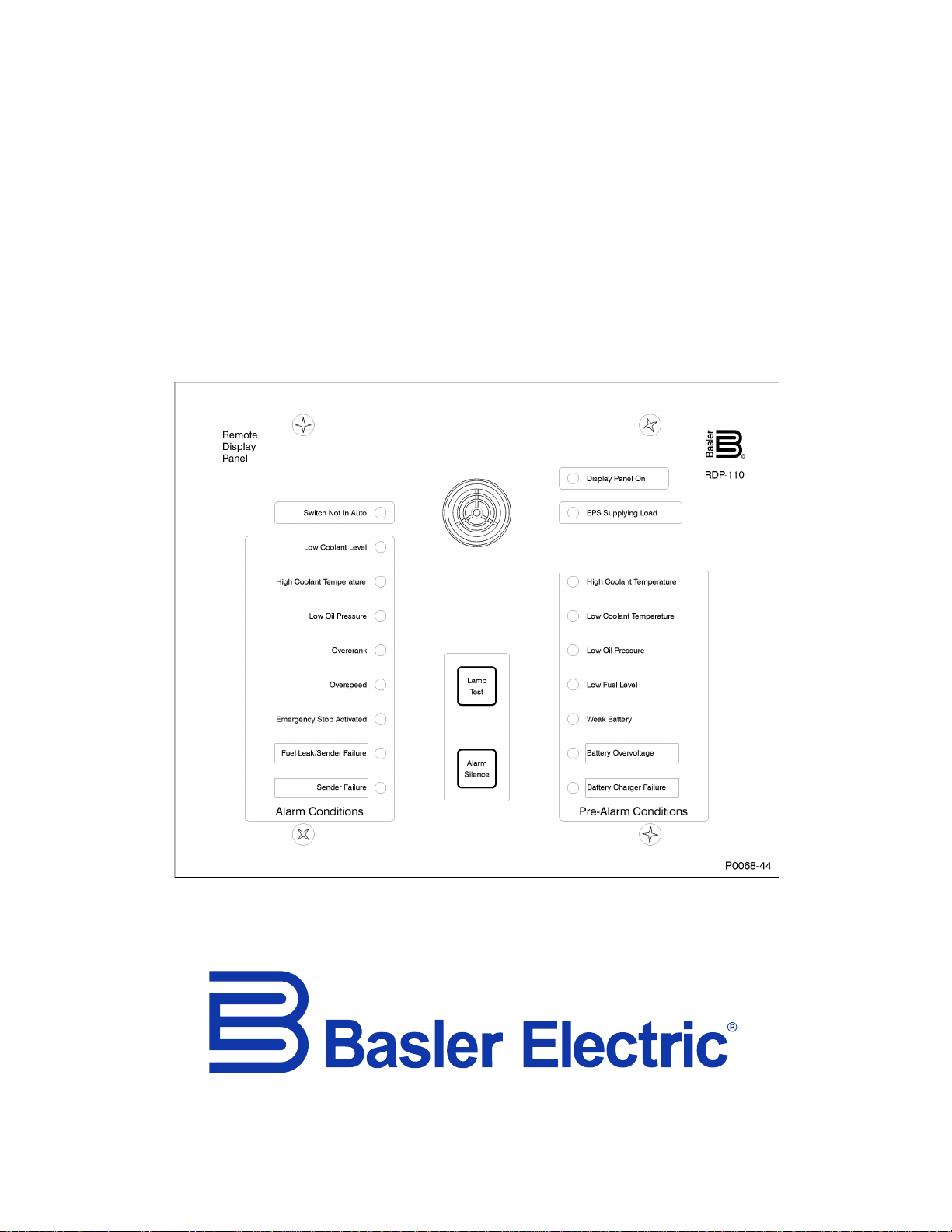
Controls and Indicators
RDP-110 controls and indicators consist of pushbuttons, LED lamps, and an audible alarm (horn). These
front panel elements are illustrated in Figure 2. Lettered locators in Figure 2 correspond to the lettered
descriptions of Table 2.
Figure 2. Controls and Indicators
Table 2. Control and Indicator Descriptions
Conditions annunciated by the pre-alarm LEDs include high coolant temperature, low
coolant temperature, low oil pressure, low fuel level, weak battery, battery overvoltage, and
battery charger failure. When the RDP-110 is used with a DGC-2020, the bottom two LEDs
(Battery Overvoltage and Battery Charger Failure) can be reprogrammed to indicate other
pre-alarm conditions. See Programmable Alarm and Pre-Alarm Configuration for
RDP-110 1BControls and Indicators
horn (locator C). The Lamp Test pushbutton can be used to verify operation of all RDP-110
Page 14

6 9318100990 Rev H
Locator
Description
F
The red Alarm LEDs light when the corresponding alarm setting is exceeded. Conditions
Configuration for information about configuring the two programmable alarm indicators.
G
Red Switch Not In Auto LED lights when the DGC is not operating in Auto mode.
annunciated by the alarm LEDs include low coolant level, high coolant temperature, low oil
pressure, overcrank, overspeed, emergency stop activated, fuel leak/sender failure, and
sender failure. When the RDP-110 is used with a DGC-2020, DGC-202 0E S, or
DGC-2020HD, the bottom two LEDs (Fuel Leak/Sender Failure and Sender Failure) can be
reprogrammed to indicate other alarm conditions. See Programma ble Alarm and Pr e-Alarm
Programmable Alarm and Pre-Alarm Indicator Configuration
When used with a DGC-2020, DGC-2020ES, or DGC-2020HD, the RDP-110 has the added capability of
programmable alarm and pre-alarm indicators. This ability applies only to the DGC-2020, DGC-2020ES,
or DGC-2020HD and is not available when the RDP-110 is paired with the DGC-500 or DGC-1000.
Up to two alarm LEDs and two pre-alarm LEDs may be reprogrammed to suit the needs of a particular
application. The two bottommos t alarm LEDs ar e pre-configured in DGC logic to annunciate a fuel
leak/sender failure and sender failure. The two bottommost pre-alarm LEDs are pre-configured in DGC
logic to annunciate battery overvoltage and a battery charger failure. These LEDs are labeled as such
with replaceable cards (Figure 3) that can be relabeled to match the function of each programmable
indicator.
Figure 3. Programmable Alarm and Pre-Alarm Label Cards
Information about configuring DGC logic to provide other alarm and pre-alarm annunciations is available
in the appropriate DGC instruction manual. To re-label the RDP-110 programmable alarm and pre-alarm
LEDs, perform the following steps.
1. Print the label text on readily-available addr es s label sheets. The label cards accommodate
adhesive-backed labels measuring 0.5 by 1.75 inches. Avery part number 18167 is suitable for
this purpose.
2. Remove all control power from the RDP-110.
3. Remove the four Phillips screws from the front panel and separate the front panel from the
conduit box. Disconnect the two connectors attached to the circuit board mounted to the front
panel. When handling the front panel, avoid touching the circuit board.
4. Lay the front panel face-down on a suitable work surface.
5. Grasp the tab of the label card to be changed and pull free. The two label cards are located near
the two lower corners of the circuit board. When facing the back of the panel, the pre-alarm label
card is on the left and the alarm label card is on the right.
6. Apply the labels created in step 1 to the label cards. The rectangle outlines on each label card
1BControls and Indicators RDP-110
serve as guides for attaching the labels.
Page 15

9318100990 Rev H 7
7. After applying the new labels, insert each label card into the appropriate panel slot. Ensure that
each label card is oriented properly by viewing the custom labels through the label windows of the
front panel.
8. Move the panel assembly adjacent to the conduit box and reconnect the cables to the two circuit
board connectors.
9. Secure the front panel to the conduit box with the four Phillips screws removed in step 3.
Maximum torque for these screws is 17 inch-pounds or 2 newton meters.
10. If desired, verify the function of the reprogrammed indicators before returning the RDP-110 to
service.
RDP-110 1BControls and Indicators
Page 16

8 9318100990 Rev H
1BControls and Indicators RDP-110
Page 17

9318100990 Rev H 9
Microprocessor
Power
Supply
RS-485
Interface
Lamp
Test
Alarm
Silence
LED Indicators Audible Alarm
12/24 Vdc
100/120 Vac
From DGC
D2829-19
Functional Description
The RDP-110 uses microprocessor-based technology to provide remote annunciation of engine and
generator parameters. RDP-110 function blocks are illustrated in Figure 4 and described in the following
paragraphs.
Figure 4. RDP-110 Function Blocks
Inputs
RDP-110 inputs consist of control power inputs, a communication interface, and pushbuttons. Control
power and communication connections are made on the circuit board attached to the front panel.
Control Power
Redundant, isolated control power inputs enable continued RDP-110 operation if one power input is lost.
The dc control power input accepts nominal battery voltage of 12 Vdc or 24 Vdc. The acceptable range of
dc control power is 8 to 32 Vdc.
The ac control power input is rated for a nominal voltage of 100 Vac or 120 Vac at 50 Hz or 60 Hz. The
acceptable range of ac control power is 80 to144 Vac.
Each control power input is applied to an internal switching power supply that provides filtered 5 Vdc
operating power for the RDP-110 circuitry.
Communication Interface
RDP-110 annunciation commands are received from the DGC over an RS-485 serial communication bus.
Received communication inputs are converted to signals suitable for use by the RDP-110
microprocessor.
Pushbuttons
Two front-panel pushbuttons accept local inputs: Lamp Test and Alarm Silence.
LED and horn operation can be verified by pressing the Lamp Test pushbutton.
An audible alarm is reset by pressing the Alarm Silence pushbutton. Once reset, the horn is reactivated
only the occurrence of another, separate pre-alarm or alarm condition.
RDP-110 4BFunctional Description
Page 18

10 9318100990 Rev H
Microprocessor
The microprocessor executes embedded firmware which interprets commands received from the DGC
and annunciates pre-alarm and alarm conditions by lighting the appropriate indicators and sounding the
horn.
Firmware
Embedded firmware controls power-up initialization, annunciation element setup, and serial
communication. When control power is applied to the RDP-110, the firmware initiates a power-up
sequence, checks the onboard memory, activates all annunciation functions, and begins monitoring for
inputs from the DGC.
4BFunctional Description RDP-110
Page 19

9318100990 Rev H 11
Note
Installation
A NEMA 1 enclosure makes the RDP-110 resistant to moisture and dust infiltration. Its metal construction
improves immunity to electromagnetic interference. Conduit knockouts on the case enable the RDP-110
to be used as a “pass-through” or junction box for other site wiring. Two available mounting configurations
provide the option of semi-flush mounting or surface (projection) mounting.
If the RDP-110 will not be installed immediately, store it in the original shipping package in a moistureand dust-free environment.
Mounting
RDP-110 mounting dimensions are illustrated in Figure 5.
Figure 5. RDP-110 Mounting Dimensions
Connections
Display panel connections are made with two plug-in connectors that mate with headers on the lower
edge of the RDP-110 circuit board. Keyed connectors prevent improper connections. These circuit board
connections, illustrated in Figure 6, are accessed by removing the front panel from the conduit box.
Ensure that the RDP-110 is hard-wired to earth ground with no smaller
than 16 AWG (1.5 mm
CHASSIS terminal. An additional ground connection is provided on the
conduit box.
DC control power applied to the 12/24 (+) and DC COM (–) terminals
must be of the correct polarity. Incorrect dc control power polarity will
prevent the RDP-110 from functioning.
RDP-110 4BInstallation
2
) copper wire attached to the circuit board
Page 20

12 9318100990 Rev H
Note
The 240 terminal is not functional and cannot be used. For ac control
power connections, only the 120 and AC COM terminals should be
used for application of 100/120 Vac nominal voltage.
Figure 6. RDP-110 Circuit Board Connections
Connector Wiring
Note the following guidelines when wiring the two circuit board connections:
• The ground terminal connection should be made with wire no smaller than 16 AWG (1.5 mm
• Other than the ground terminal, connections should be made with wire no smaller than 20 AWG
(0.5 mm
• Maximum conductor size for each terminal is 12 AWG (4 mm
2
)
2
)
2
)
• Strip the insulation from each wire to reveal 0.28 inches (7 millimeters) of exposed conductor
• Apply no more than 4.4 in-lb (0.5 N●m) of torque to each terminal screw
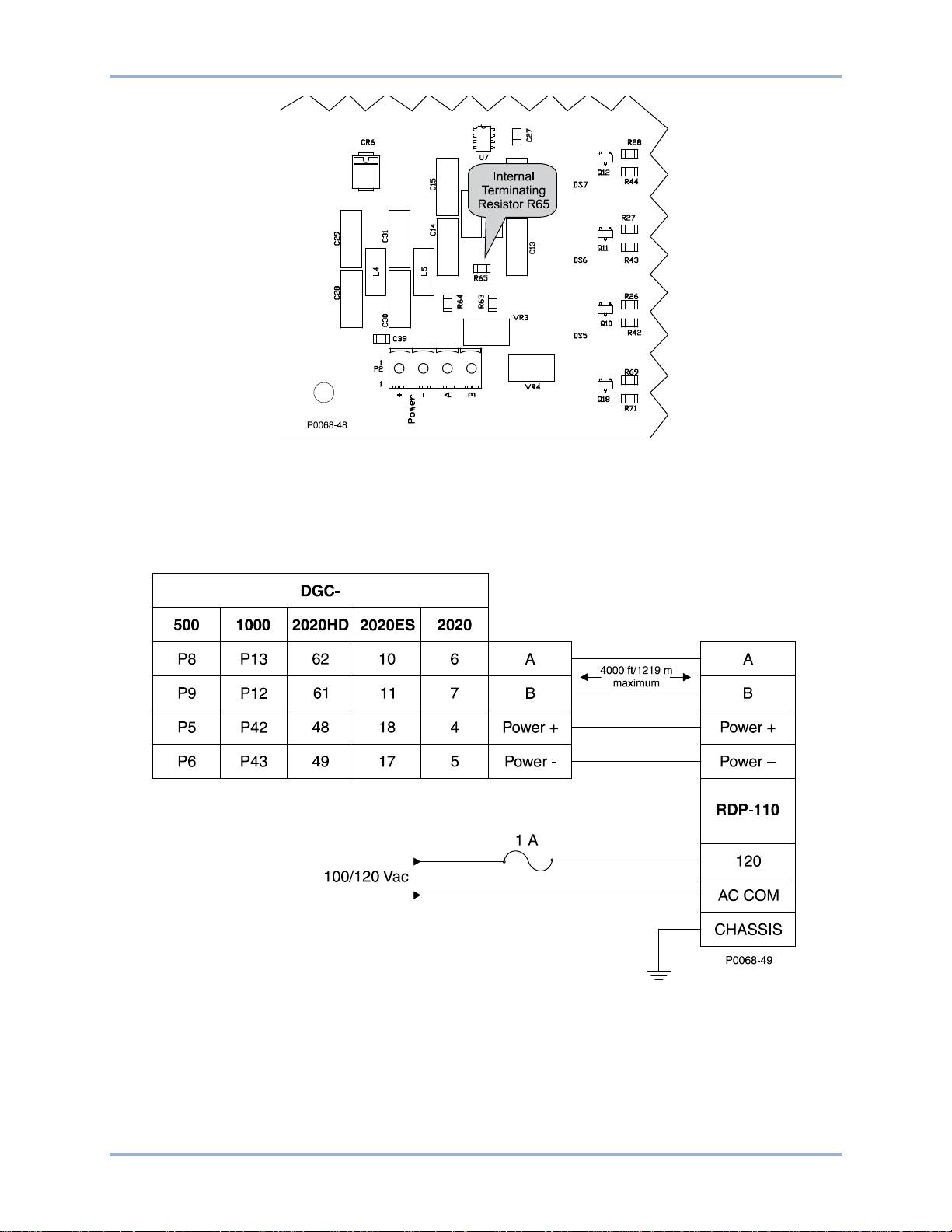
RS-485 Communication Connections
Twisted-pair conductors are recommended for the communication wiring between the DGC and
RDP-110.
Overly long wiring runs may impair com mun ic at ion bet ween the DGC and RDP-110 unreliable. Do not
exceed an RS-485 conductor length of 4,000 feet (1,219 meters).
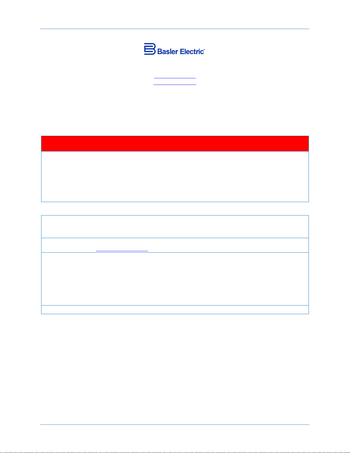
RS-485 Terminating Resistor
The RS-485 communication connection is internally terminated with a 100 Ω resistor. Connecting multiple
display panels may necessitate removal of this terminating resistor (R65). R65 is located in the lower, left
quadrant of the circuit board. The location of R65 is illustrated in Figure 7.
Consult standard TIA/EIA-485 for guidance on the electrical requirements of multipoint communication
systems.
4BInstallation RDP-110
Page 21
9318100990 Rev H 13
Figure 7. RS-485 Terminating Resistor Locati o n
Typical Connections
Typical RDP-110 connections are shown in Figure 8.
Figure 8. Typical RDP-110 Connections
RDP-110 4BInstallation
Page 22

14 9318100990 Rev H
4BInstallation RDP-110
Page 23

9318100990 Rev H 15
Testing
A built-in test mode enables field testing of RDP-110 operation.
Test Equipment and Setup
Equipment needed for testing RDP-110 operation is listed below. Connections for the test are illustrated
in Figure 9.
• Power supply, 24 Vdc
• Power source, 100/120 Vac, 50/60 Hz
• Fuse, 1 ampere (2)
• Signal generator, 10 Hz, square wave, 5 volts peak-to-peak
Figure 9. RDP-110 Test Setup
Test Procedure
1. Connect the RDP-110 tes t setup as sh own in Figure 9.
2. Apply 24 Vdc control power. The Display Panel On LED should light.
3. Press and hold the Lamp Test pushbutton. All LEDs should light and the horn should sound.
4. Release the Lamp Test pushbutton to reset the indicators and horn.
5. Apply the 10 Hz signal.
6. Press and release the Lamp Test pushbutton. Observe that the LEDs and horn annunciate in the
eighteen-step sequence indicated in Figure 10. This sequence will repeat until the Alarm Silence
pushbutton is operated.
7. Press and release the Alarm Silence to end the annunciation sequence.
8. Remove the 10 Hz signal and 24 Vdc control power.
9. Repeat the test with 100/120 Vac control power applied instead of 24 Vdc control power.
RDP-110 1BTesting
Page 24

16 9318100990 Rev H
Figure 10. Test Mode Annunciation Sequence
1BTesting RDP-110
Page 25

Page 26

12570 State R oute 143
Highland IL 62249-1074 USA
Tel: +1 618.654.23 4 1
Fax: +1 618.654.2351
email: info@basler.com
P.A.E. Les Pins
67319 Wasselonne Cedex
FRANCE
Tel: +33 3.88.87.1010
Fax: +33 3.88. 87.0808
email: franceinfo@basler.com
No. 59 Heshun Road Loufeng District (N)
Suzhou Indus trial Park
215122 Suzhou
P.R. CHINA
Tel: +86 512.8227.2888
Fax: +86 512.8227.2887
email: chinainfo@basler.com
111 North Bridge Road
15-06 Peninsul a Plaz a
Singapore 1 79098
Tel: +65 68.4 4.6445
Fax: +65 68.44.8902
email: singaporeinfo@basler.com
 Loading...