

Page 1

INSTRUCTION MANUAL
FOR
ELECTRONIC MANUAL VOLTAGE CONTROL
Model: MVC 301
Part Number: 9 1210 00 107
Publication Number: 9 1210 00 994
Revision B: 12/99
Page 2
WARNING
To prevent personal injury or equipment damage, only qualified technicians/operators should install, operate, or service
this device.
CAUTION
Meggers and high potential test equipment should be used
with extreme care. Incorrect use of such equipment could
damage components contained in the device.
CONFIDENTIAL INFORMATION
of Basler Electric Company, Highland, IL. It is loaned for
confidential use. Subject to return on request and with the
mutual understanding that it will not be used in any manner
detrimental to the interests of Basler Electric Company.
It is not the intention of this manual to cover all details and
variations in equipment, nor does it provide data for every
possible contingency regarding installation or operation.
The availability and design of all features and options are
subject to change without notice. Should further information
be required, call Basler Electric Company, Highland, IL.
Page 3
SECTION 1
GENERAL INFORMATION
1-1. PURPOSE
The Electronic Manual Voltage Control (MVC-301) is used as a back-up control device to provide
manual voltage control in case of voltage regulator failure. The un i t can be mounted on a control
panel in ground vehicles, stationary equipment or shipboard locations.
1-2. OVERALL DESCRIPTION
The MVC-301 is a solid-state device enclosed in a metallic dark grey chassis and designed to be
'through-the-panel' mounted with the control accessible to an operator from the front of the panel.
A terminal strip located on the rear of the device facilitates installation and operation. An
AUTO-OFF-MANUAL
1-3. SPECIFICATIONS
Table 1-1 provides the electrical and physical specifications of the MVC 301.
voltage control mode switch is provided on the front panel.
Table 1-1. Specifications.
Input Power:
Output Adjustment
Range:
120 Vac Input:
240 Vac Input:
Watts Dissipated:
Minimum Residual
Voltage for Buildup:
Ambient Operating
Temperature:
Ambient Storage
Temperature:
Shock
Vibration:
Weight:
120 Vac, Single-Phase.
240 Vac, Single-Phase.
1 to 32 Vdc or 1 to 63 Vdc.
1 to 63 Vdc or 1 to 125 Vdc.
30 W maximum.
6 Vac.
-40 F (-40 C) to +158 F (+70 C)
-85 F (-65 C) to +212 F (+100 C)
Withstands up to 15 G's in each of three mutually perpendicular
axes.
Withstands the following:
5 - 27 Hz @ 1.3 G's,
27 - 52 Hz @ 0.036" double amplitude,
52 - 500 Hz @ 5 G's.
3.0 lbs. (1.36 kg) net, 5 lbs. (2.26 kg) shipping.
1-1
Page 4

Page 5

SECTION 2
PRINCIPLES OF OPERATION
2-1. GENERAL
a. The Electronic Manual Voltage Control (MVC-301) is a phase-controlled, silicon-controlled,
rectifier (SCR) bridge. By adjusting the external
angle of the SCR change providing an adjustable voltage level to the exciter field.
b. During start-up, the build-up circuit holds the SCRs power bridge at maximum output. When the
voltage has built-up to approximately 30 Vac, the internal build-up circuit relinquishes control to the
external
MANUAL VOLTAGE ADJUST
.
MANUAL VOLTAGE ADJUST
control, the firing
c. The
the Manual Voltage Control or from Manual Voltage Control to voltage regulator. A free wheeling
diode remains connected to the field to allow safe switching without arcing.
d. The MVC-301 is designed to operate from 120 or 240 Volt nominal sources without any electrical
changes such as tap selection or terminal connections. Taps are provided to select 32, 63, or 125
volt maximum outputs.
AUTO-OFF-MAN
voltage control mode switch allows transfer from the voltage regulator to
2-1
Page 6

Page 7

SECTION 3
INSTALLATION AND OPERATION
3-1. INSTALLATION
a. The MVC-301 is designed for 'through-the-panel' mounting. Refer to the drilling template of
Figure 3-1 and to the outline drawing Figure 3-2. The front panel of the MVC-301 is detachable by
removal of the four corner screws. The MVC-301 can be installed in any position without affecting
its operating characteristics, however, it is preferable that the device be mounted vertically to
improve ventilation. The
nals 14, 15 and 16 or a Basler motor operated control (MOC 2) with a 10 k ohm control element can
be connected to terminal 14, 15, and 16. See Figure 3-3 Interconnection Diagram. It is imperative
that the MVC-301 be connected to provide an output which corresponds to the voltage regulator
ratings in order to prevent damage to the MVC-301 or the regulator. When the MVC-301 and
voltage regulator are properly matched, the MVC-301 provides smooth control of the generator
output voltage in the manual mode.
b. The chart (Table 3-1) is used to determine the appropriate input voltage and to select the output
voltage. Based on voltage regulator model, from column 1, the proper voltage input rating from
column 3 is selected and connections are made between the generator and terminals 23 and 24
which will supply the specified voltage. The MVC-301 has a wire jumper connected from the printed
circuit board of the MVC-301 to the barrier strip. Column 4 indicates the correct terminal for this
jumper connection.
MANUAL VOLTAGE ADJUST
control can be connected by using termi-
3-1
Page 8

Figure 3-1. Panel Drilling Template
3-2
Page 9

Figure 3-2. MVC 301 Outline Drawing.
3-3
Page 10

Figure 3-3 MVC 301 Interconnection Diagram, Typical
3-4
Page 11

Table 3-1. Voltage Selection Chart.
Voltage Regulator
Model
KR7F,KR7FF,
SR8A,SR8F
SR4A,SR4F,
KR4F,KR4FF
XR2001,XR2004 63 V @ 7 A or less 240 Vac 63
KR2F,KR2FF 32 V @ 7 A or less 120 Vac 32
APR63-5 63 V @ 7 A or less 240 Vac 63
APR125-5 125 V @ 7 A or less 240 Vac 125
HP63 63 V @ 7 A or less 240 Vac 63
Voltage Regulator
Rating
125 V @ 7 A or less 240 Vac 125
63 V @ 7 A or less 120 Vac 63
MVC Input
Voltage
Voltage Selection
Terminal
3-2. OPERATION
a. With the
voltage regulator is removed from the line and generator output voltage is controlled manually by
MANUAL VOLTAGE ADJUST
the
generator output voltage is controlled by the automatic voltage regulator. Complete excitation
shutdown occurs when the voltage control mode switch is placed in the
AUTO-OFF-MANUAL
voltage control mode switch placed in
control. When placed in the
MANUAL
AUTOMATIC
OFF
position.
, the automatic
position, the
CAUTION
With the voltage control mode switch in either MANUAL or
OFF position, some terminals of the regulator are connected
to the generator and present a potential shock hazard. No attempt should be made to remove or troubleshoot the regulator
while the generator is running.
b. Start the prime mover following the manufacturer's procedure, set the
ADJUST
voltage control mode switch in
if the
c. Allow the generator to build-up and slowly increase the generator output voltage with the
AL VOLTAGE ADJUST
control to minimum (counter-clockwise), and place the
MANUAL
MANUAL VOLTAGE ADJUST
control until the generator output voltage reaches the desired level.
position. Note that the voltage may be unstable (hunting)
control is set below 30 Vac.
AUTOMATIC-OFF-MANUAL
MANUAL VOLTAGE
MANU-
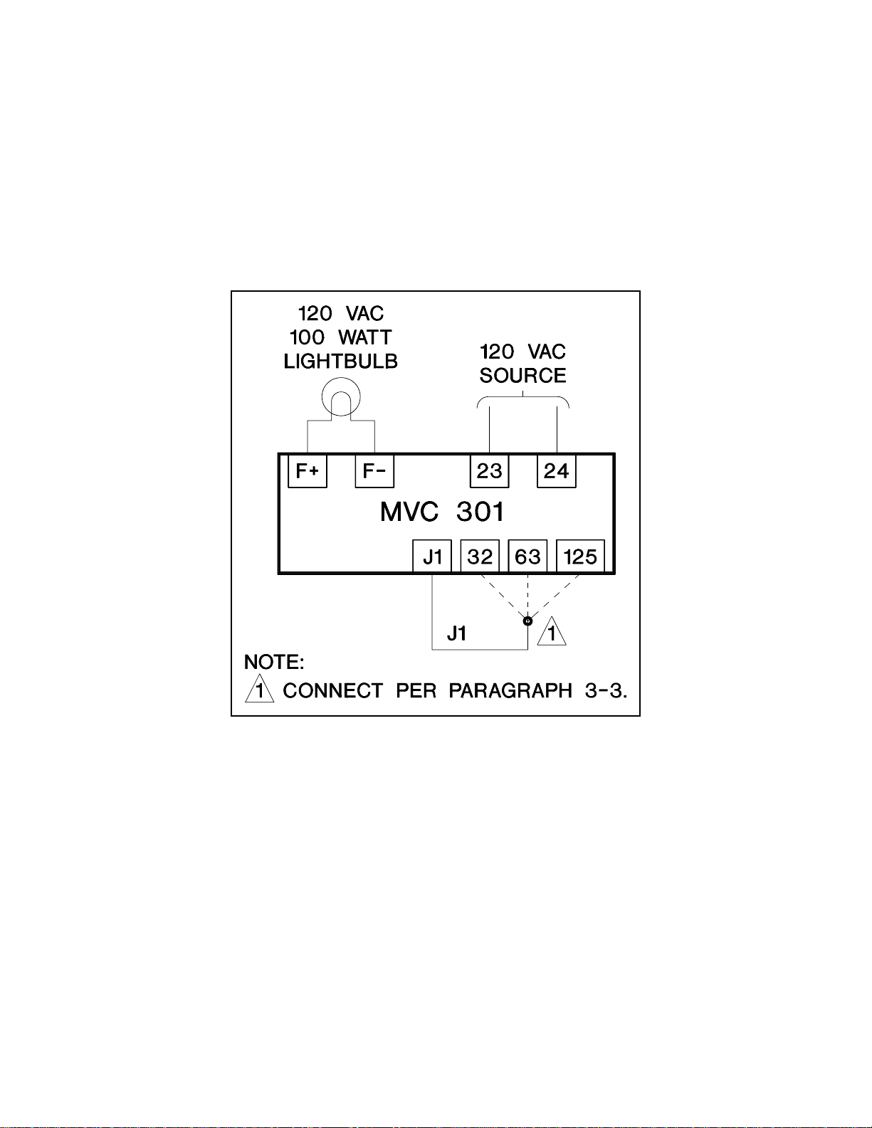
3-3. OPERATIONAL TEST
To verify that the MVC-301 is operating properly, use the following procedure and the connections
of Figure 3-4 for a bench test. Notice that the voltage regulator is not necessary for this test.
(1) With no power applied to the MVC-301 and all connections to the voltage regulator
removed, place the
MANUAL
position.
AUTO-OFF-MANUAL
voltage control mode switch to the
(2) Connect a 120 Vac 100 Watt light bulb to terminals F+ and F- of the MVC-301, and
connect the jumper to Terminal 63.
3-5
Page 12
(3) With the
apply a source of 120 Vac to Terminals 23 and 24 of the MVC-301. Slowly rotate
MANUAL VOLTAGE ADJUST
the
brightness of the light bulb increases proportionally until it reaches full brightness.
MANUAL VOLTAGE ADJUST
control clockwise (CW) and observe that the
control fully counter-clockwise (CCW)
(4) Rotate the
Remove the 120 Vac source from Terminals 23 and 24 and select 32 volt operation
by moving the jumper to Terminal 32. Apply the 120 Vac source to Terminals 23
and 24 of the MVC and observe that the brightness of the light bulb increases as
MANUAL VOLTAGE ADJUST
the
the brightness of the bulb is approximately half of its previous brightness with the
jumper connected to this terminal.
MANUAL VOLTAGE ADJUST
control is moved clockwise (CW). Notice that
control fully counter-clockwise (CCW).
Figure 3-4. Bench Test Connections.
3-6
Page 13

SECTION 4
MAINTENANCE AND TROUBLESHOOTING
4-1. PREVENTIVE MAINTENANCE
A periodic inspection should be made of the unit to insure it is clean and free from accumulations
of dust and moisture. Verify that all terminal connections of the MVC-301 and the voltage regulator
are tight.
4-2. TROUBLESHOOTING
In the event of failure/defective operation of the unit, Table 4-2 provides information to determine
the probable cause of the malfunction and the solution. Refer to Paragraph 3-3 and to Figure 3-4
for the bench test procedure.
4-3. RECOMMENDED SPARE PARTS
Due to a protective coating, repair/replacement of individual components on the printed circuit board
assembly should not be attempted and the complete replacement of the board is recommended.
When ordering replacement parts from Basler Electric always specify the part number, the quantity
and the description of the item.
Table 4-1. Replacement Parts List.
Reference
Designator
---------------- 9 1210 01 104 1 Printed Circuit Board Assembly
F1,F2 04592 2 Fuse, 10 A, 250 V
Part
Number Quantity Description
4-1
Page 14

Table 4-2. Troubleshooting.
MALFUNCTION
TEST OR INSPECTION
CORRECTIVE ACTION
MVC 301 APPEARS TO BE DEFECTIVE.
Step 1.
Step 2.
Step 3.
Step 4.
Verify that wiring is correct and proper in accordance with Figure 3-3.
If wiring is defective or incorrect, repair as needed.
If wiring is not defective or incorrect, proceed to Step 2.
Check that the
If the excitation does not turn off, replace the MVC 301.
If the excitation shuts down, proceed to Step 3.
With the
output voltage builds up.
If the generator output voltage builds up, proceed to Step 6.
If the generator output voltage does not build up, proceed to Step 4.
Verify that internal fuses F1 and F2 are good.
If either fuse is defective or blown, replace fuse and proceed to Step 5.
AUTO-OFF-MAN
AUTO-OFF-MAN
front panel switch turns off the excitation.
front panel switch in
MANUAL
, verify that the generator
Step 5.
Step 6.
Step 7.
If both fuses are not defective or blown, replace the MVC 301.
Verify that the generator output voltage builds-up.
If the generator output voltage does not build-up, replace the MVC 301.
If the generator output voltage builds-up, proceed to Step 6.
Verify that the generator output can be c ontrolled by the MVC 301 front panel
potentiometer.
If the generator output voltage cannot be controlled by the MVC 301,
replace the MVC 301.
If the generator output voltage can be controlled by the MVC 301, proceed
to Step 7.
Verify that the generator works in the front panel switch
If the generator fails to operate with the front panel switch in the
position, troubleshoot the voltage regulator.
AUTO
position.
AUTO
4-2
Page 15

Page 16

ROUTE 143, BOX 269
HIGHLAND, IL 62249 USA
http://www.basler.com, info@basler.com
PHONE +1 618-654-2341 FAX +1 618-654-2351
 Loading...