

Page 1
INSTRUCTION MANUAL
FOR
MVC 236
Manual Voltage Control
Publication: 9204300990
Revision: J 09/13
Page 2

Page 3

9204300990 Rev J i
Preface
This instruction manual provides information about the installation and operation of the MVC 236 Manual
Voltage Control. To accomplish this, the following information is provided:
Functional description
Mounting
Connections
Operation
Maintenance
Conventions Used in this Manual
Important safety and procedural information is emphasized and presented in this manual through
Warning, Caution, and Note boxes. Each type is illustrated and defined as follows.
Warning!
Warning boxes call attention to conditions or actions that may cause
personal injury or death.
Caution
Caution boxes call attention to operating conditions that may lead to
equipment or property damage.
Note
Note boxes emphasize important information pertaining to Manual
Voltage Control installation or operation.
Manual Voltage Control Preface
Page 4
ii 9204300990 Rev J
12570 State Route 143
Highland IL 62249-1074 USA
www.basler.com
info@basler.com
Tel: +1 618.654.2341
Fax: +1 618.654.2351
© 2013 by Basler Electric
All rights reserved
First printing: August 1988
Warning!
READ THIS MANUAL. Read this manual before installing, operating, or maintaining the MVC 236.
Note all warnings, cautions, and notes in this manual as well as on the product. Keep this manual with
the product for reference. Failure to follow warning and cautionary labels may result in personal injury
or property damage. Exercise caution at all times.
To prevent personal injury or equipment damage, only qualified personnel should install, operate, or
service this system.
Basler Electric does not assume any responsibility to compliance or noncompliance with national code, local code,
or any other applicable code. This manual serves as reference material that must be well understood prior to
installation, operation, or maintenance.
For terms of service relating to this product and software, see the Commercial Terms of Products and Services
document available at www.basler.com/terms.
This publication contains confidential information of Basler Electric Company, an Illinois corporation. It is loaned for
confidential use, subject to return on request, and with the mutual understanding that it will not be used in any
manner detrimental to the interests of Basler Electric Company and used strictly for the purpose intended.
It is not the intention of this manual to cover all details and variations in equipment, nor does this manual provide
data for every possible contingency regarding installation or operation. The availability and design of all features
and options are subject to modification without notice. Over time, improvements and revisions may be made to this
publication. Before performing any of the following procedures, contact Basler Electric for the latest revision of this
manual.
The English-language version of this manual serves as the only approved manual version.
Preface Manual Voltage Control
Page 5

9204300990 Rev J iii
Contents
Introduction ................................................................................................................................................... 1
Functional Description ................................................................................................................................... 3
Buildup Circuit ........................................................................................................................................... 3
Auto/Manual Transfer ................................................................................................................................ 3
Output Power ............................................................................................................................................. 3
Spike Suppression ..................................................................................................................................... 3
Mounting ........................................................................................................................................................ 5
Spike Suppression Module ........................................................................................................................ 6
Connections .................................................................................................................................................. 7
Operation..................................................................................................................................................... 11
Operational Test ...................................................................................................................................... 11
Maintenance ................................................................................................................................................ 13
Troubleshooting ....................................................................................................................................... 13
Specifications .............................................................................................................................................. 15
Manual Voltage Control Contents
Page 6

iv 9204300990 Rev J
Contents Manual Voltage Control
Page 7

9204300990 Rev J 1
Introduction
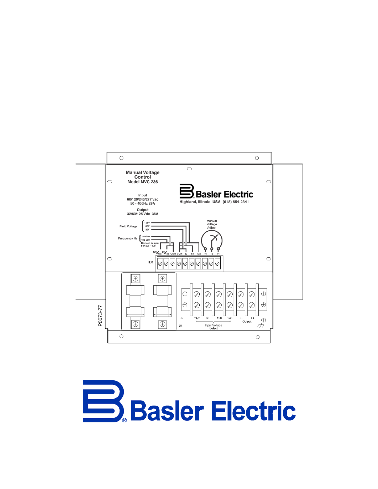
Manual Voltage Control MVC 236 enables manual control of generator output and is intended as a
backup system for an associated automatic voltage regulator. During generator startup, an integrated
buildup circuit maintains maximum MVC 236 output power for reliable buildup of the generator output
voltage.
The MVC 236 is intended for behind-the-panel mounting. MVC 236 components are mounted on a 14gauge, steel chassis with an aluminum cover and heat sinks. MVC 236 modules with part number
9204300100 have a chassis constructed from low-carbon steel while MVC 236 modules with part number
9204300104 have a chassis constructed from 316-grade stainless steel.
Standard Equipment
The MVC 236 is supplied with a potentiometer and spike suppression module.
Potentiometer
The potentiometer is intended for remote mounting and controls the MVC 236 setpoint.
Spike Suppression Module
The spike suppression module protects the MVC 236 from potentially damaging voltage spikes when the
MVC 236 is powered by a high-impedance source.
Optional Equipment
Available optional equipment for the MVC 236 includes an Auto/Off/Manual control switch and a nulling
chassis.
Auto/Off/Manual Switch
An available Auto/Off/Manual switch (P/N 9204306100) enables transfer of control between the MVC 236
and automatic voltage regulator.
Nulling Chassis
An available nulling chassis (P/N 9204304100) provides “bumpless” transfers from the automatic voltage
regulator to the MVC 236.
MVC 236 Introduction
Page 8

2 9204300990 Rev J
Introduction MVC 236
Page 9

9204300990 Rev J 3
Voltage Adjust
Error
Amplifier
Power
Supply
SCR
Control
Output
Input
P0073-70
Functional Description
The MVC 236 supplies power to the generator field through a phase-controlled, silicon-controlled rectifier
(SCR) bridge. By adjusting the remotely-mounted, manual voltage adjust control, the firing angle of the
SCR changes to provide an adjustable voltage level to the exciter field.
A simplified block diagram illustrating MVC 236 operation is shown in Figure 1.
Figure 1. MVC 236 Block Diagram
Operating Power
MVC 236 operating power can be supplied from a source with a nominal rating of 60 Vac, 120 Vac, or
240 Vac. The nominal source voltage is made on the MVC 236 through a tap selection.
The operating power frequency can be within one of three jumper-selectable ranges: 50 to 100 Hz, 100 to
200 Hz, or 200 to 400 Hz.
Buildup Circuit
During generator startup, the MVC 236 buildup circuit holds the SCR power bridge at maximum output.
Once the voltage builds to approximately 30 Vac, the buildup circuit relinquishes control to the remotelymounted, potentiometer for manual control of the field excitation level.
Auto/Manual Transfer
The available Auto/Off/Manual switch (P/N 9204306100) enables transfer from the automatic voltage
regulator to the MVC 236 and vice versa. Circuitry within the MVC 236 allows safe switching without the
risk of arcing.
Output Power
The jumper-selectable MVC 236 power output is rated for a nominal field voltage of 32 Vdc, 63 Vdc, or
125 Vdc.
Spike Suppression
Higher impedance sources, such as power isolation transformers and permanent magnet generators
(PMGs), may have enough inductance to produce damaging voltage spikes in the MVC 236 power output
stage. In these applications, use of the provided spike suppression module is recommended to filter out
MVC 236 Functional Description
Page 10

4 9204300990 Rev J
these potentially damaging voltage spikes. The Installation chapter provides information about mounting
and connecting the spike suppression module.
Functional Description MVC 236
Page 11

9204300990 Rev J 5
Mounting
For maximum cooling, the MVC 236 must be mounted vertically. The mounting location can be anywhere
the ambient temperature does not exceed the environmental conditions listed in the Specifications
chapter. Figure 2 illustrates the overall mounting dimensions of the MVC 236. Maximum mounting depth
for the MVC 236 is 4.375 inches (111 millimeters). Dimensions shown in Figure 2 are in inches with
millimeters in parenthesis.
Figure 2. MVC 236 Mounting Dimensions
Manual Voltage Adjust Potentiometer
Mounting dimensions for the manual voltage adjust potentiometer are shown in Figure 3.
MVC 236 Mounting
Page 12

6 9204300990 Rev J
Figure 3. Manual Voltage Adjust Potentiometer Dimensions
Spike Suppression Module
The spike suppression module can be mounted in any position and location where the ambient
temperature does not exceed the operational limits. Due to the rugged construction of the spike
suppression module, it can be mounted direc t ly on the genera tor . Select module mounting hardware
based on the vibration and shock expected during normal operation. Figure 4 illustrates the overall and
mounting dimensions for the spike suppression module. Dimensions shown in Figure 4 are in inches with
millimeters in parenthesis.
Figure 4. Spike Suppression Module Mounting Dimensions
Mounting MVC 236
Page 13

9204300990 Rev J 7
Caution
Contact
1-2
1-3
5-4
5-6
7-8
9-10
11-12 †
13-14 †
15-16 †
17-18 †
Manual
X X X
∗
X
Off X
∗
Auto X X X X X X X
Connections
High-potential test equipment should be applied with extreme care.
Incorrect application of dielectric test voltages will damage the
MVC 236.
Connection drawings for typical MVC 236 applications are provided in Figure 5 and Figure 6.
Table 1 serves as a legend for the Auto/Off/Manual Switch of Figure 5.
For Figure 6, switch contacts 1 and 2 are closed for manual operation and switch contacts 3 and 4 are
closed for auto operation.
Table 1. Auto/Off/Manual Switch Legend for Figure 5
Switch
Position
∗ Make before break.
† Contacts required for automatic voltage regulator maintenance.
Connection Guideli ne s
Observe the following guidelines when making MVC 236 connections.
Input Power
Operating power is applied at MVC 236 terminals 23 and 24. The MVC 236 and operating power wiring
should be protected with fuses. Configure the MVC 236 for the applied, nominal operating power by
connecting the jumper from terminal TB2-TAP to the proper terminal on TB2 (60, 120, or 240).
Output (Field) Voltage
Select the desired output (field) voltage (32 Vdc, 63 Vdc, or 125 Vdc) by connecting the jumper wire from
terminal TB1-COM (F ield V olta ge) to the proper terminal.
Frequency Selection
Configure the MVC 236 for the operating power frequency. Connect a jumper wire between terminal TB1COM (Frequency Hz) and the appropriate terminal for 50 Hz to 100 Hz operation or 100 Hz to 200 Hz
operation. For an operating power frequency within the range of 200 Hz to 400 Hz, omit the jumper.
Manual Voltage Adjust Potentiometer
Connect the manual voltage adjust potentiometer to MVC 236 terminals TB1-14, TB1 -15, and TB1-16 as
shown in the connection diagrams. If desired, a Basler Electric Motor Operated Control with a 10 kΩ
control element can be used instead of the supplied potentiometer.
MVC 236 Connections
Page 14

8 9204300990 Rev J
Spike suppression module is required when isolation transformer is used.
Manual/Off/Auto switch is required for AVR maintenance.
Pha se rotatio n is ABC.
Connect tap for nominal input voltage used.
Connect jumper for generator frequency. (Jumper is removed for 200 to 400 Hz.)
Connect jumper for application field voltage.
TB1
14
15
16
TB1
COM
125
63
32
MVC 236
10K
+ - A B C
F+ F- 23 24
TAP 60 120 240
COM 50/100
100/200
3
Spike
Suppression
Module
3 4
Operating
Power
Field
Output
Current
Sensing
Voltage
Sensing
2
3
2
P0073-73
4 5
6
TB2 TB1
1098
7
1
3 2 4 6
5
13 15 17
14 16 18
11
12
GEN
A
B
C
Aut om atic Voltage Regulat or
TB2
-+
1
4
5
6
1
Figure 5. Typical MVC 236 Connections
Connections MVC 236
Page 15

9204300990 Rev J 9
Figure 6. MVC 236 Interconnection with Null Meter Circuit
MVC 236 Connections
Page 16

10 9204300990 Rev J
Connections MVC 236
Page 17

9204300990 Rev J 11
Operation
When the Auto/Off/Manual control switch is placed in the Manual position, the automatic voltage regulator
is removed from the circuit and the generator output is manually controlled by the MVC 236. When the
Auto/Off/Manual control switch is placed in the Auto position, the generator output voltage is controlled by
the automatic voltage regulator. Complete excitation shutdown occurs when the Auto/Off/Manual control
switch is placed in the Off position.
Warning!
When the Auto/Off/Manual control switch is placed in the Manual or
Off position, some of the voltage regulator terminals remain connected
to the generator and present a potential shock hazard. No attempt
should be made to remove or troubleshoot the automatic voltage
regulator during generator operation.
Operating Procedure
1. Start the prime mover according to the manufacturer’s procedure and set the manual voltage
adjust potentiometer to its minimum value (fully counterclockwise).
2. Place the Auto/Off/Manual switch in the Manual position. Note that the generator voltage may be
unstable (hunting) if the manual voltage adjust potentiometer is set below 30 Vac.
3. Allow the generator voltage to build and then slowly increase the generator output voltage with
the manual voltage adjust control until the generator output voltage reaches the desired level.
Operational Test
MVC 236 operation can be verified by using the following procedure. Operational test connections are
shown in Figure 7. Note that an automatic voltage regulator is not required for this test.
1. Connect the MVC 236 according to the connections shown in Figure 7.
2. Connect the field voltage jumper for 125 Vdc.
3. Adjust the manual voltage adjust control fully counterclockwise and apply 120 Vac input power.
4. Slowly rotate the manual voltage adjust control clockwise and observe that the brightness of the
light bulb increases proportionally until reaching full luminance.
5. Rotate the manual voltage adjust control fully counterclockwise and remove the 120 Vac input
power.
6. Connect the field voltage jumper for 63 Vdc.
7. Apply power and slowly rotate the manual voltage adjust control c lock wis e and o bser v e that the
brightness of the light bulb increases proportionally. Observe that the light bulb luminance is half
of what is was when the field voltage jumper was set in the 125 Vdc position.
8. Rotate the manual voltage adjust control fully counterclockwise and remove the 120 Vac input
power.
9. Connect the field voltage jumper for 32 Vdc.
10. Apply power and slowly rotate the manual voltage adjust control clockwise and observe that the
brightness of the light bulb increases proportionally. Observe that the light bulb luminance is half
of what is was when the field voltage jumper was set in the 63 Vdc position.
MVC 236 Operation
Page 18

12 9204300990 Rev J
120 Vac, 100 W
MVC
236
240 F– F+
120
60
TAP2423
TB2
120 Vac
Source
32 100/20063125161514 50/100COMCOM TB1
Voltage Adjust Field Voltage Frequency
Jumper for input
frequency used
See steps 2, 6, and 9
of
Operational Test
.
P0073-75
Figure 7. MVC 236 Operational Test Connections
Operation MVC 236
Page 19

9204300990 Rev J 13
Component
Designator
Basler P/N
Quantity
Description
9179201101
1
Printed circuit board assembly
9261500101
1
Spike suppression module
CR5
08608
1
Diode, type S3680
F1, F2
61627
2
Fuse, type JJS40, 40 A
PM1, PM2
42403
2
SCR power module, 800 V, 90 A
R27, R28
21564
2
Resistor, wire-wound, 15 Ω, 50 W
R32
21565
1
Potentiometer, 10 kΩ, 5%, 1 W
T1
BE22746001
1
Transformer
Maintenance
Periodic inspection should be made to ensure that the MVC 236 is clean and free from accumulations of
dust and moisture. Verify that all connections are clean, tight, and free of corrosion.
Corrective Maintenance
Due to a protective, conformal coating, repair of printed circuit components should not be attempted.
Replacement of the printed circuit board is recommended. Table lists the recommended spare parts for
the MVC 236.
Table 2. Recommended Spare Parts
Troubleshooting
If an MVC 236 malfunction is suspected, the troubleshooting chart of Figure 8 can be used to determine the probable cause of the malfunction and determine corrective actions. Refer to the Maintenance chapter for a procedure for bench-testing the MVC 236.
MVC 236 Maintenance
Page 20

14 9204300990 Rev J
Verify wiring
Replace
Auto/Off/Man.
switch
Does control switch
disable excitation?
Does gen voltage
build in Manual
mode?
Can gen voltage be
controlled by pot?
Does generator
function in Auto
mode?
Replace
MVC 236
Replace
voltage
regulator
Are fuses
F1 and F2 good?
Replace
MVC 236
Replace
fuses F1, F2
Does gen
voltage build?
MVC 236 trouble
suspected
System checkout
complete
Replace
MVC 236
NO
YES
NO NO
YES NO
YESYES
NO
YES
NO
YES
P0073-76
Figure 8. MVC 236 Troubleshooting Chart
Maintenance MVC 236
Page 21

9204300990 Rev J 15
Specifications
Power Input
Frequency
50 to 400 Hz, single-phase
Voltage Range
60 Vac Nominal: 45 to 70 Vac
120 Vac Nominal: 90 to 153 Vac
240 Vac Nominal: 170 to 305 Vac
Power Dissipation
85 W
Minimum Residual Buildup Vol tag e
10% of 60 Vac nominal input voltage or 5% of 120/240 Vac nominal input voltage.
Regulation
Accuracy
2% for a 10% change in input power and 5% for a 30% change in input power.
Temperature Stability
±5% for a 50°C temperature change
Power Output
60 Vac Nominal Input
32 Vdc at 36 Adc, nominal. No less than 40 Vdc at maximum potentiometer setting.
120 Vac Nominal Input
63 Vdc at 36 Adc, nominal. No less than 79 Vdc at maximum potentiometer setting.
240 Vac Nominal Input
125 Vdc at 36 Adc, nominal. No less than 156 Vdc at maximum potentiometer setting.
Minimum Field Resistance
32 Vdc Nominal Output: 0.88 Ω
63 Vdc Nominal Output: 1.75 Ω
125 Vdc Nominal Output: 3.47 Ω
Physical
Temperature
Operating: –40 to 70°C (–40 to 158°F)
Storage: –40 to 85°C (–40 to 185°F)
Humidity
98% noncondensing, maximum
Shock
Withstands up to 15 G in each of three mutually perpendicular axes without any degradation of
performance.
MVC 236 Specifications
Page 22

16 9204300990 Rev J
Vibration
Withstands up to 2 G of force over a frequency spectrum of 10 to 500 Hz.
Weight
Unit: 6.8 kg (15.0 lb)
Shipping: 8.2 kg (18.0 lb)
Dimensions
Refer to the Mounting chapter for MVC 236 dimensions.
Specifications MVC 236
Page 23

Page 24

12570 State Route 143
Highland IL 62249-1074 USA
Tel: +1 618.654.2341
Fax: +1 618.654.2351
email: info@basler.com
P.A.E. Les Pins
67319 Wasselonne Cedex
FRANCE
Tel: +33 3.88.87.1010
Fax: +33 3.88.87.0808
email: franceinfo@basler.com
No. 59 Heshun Road Loufeng District (N)
Suzhou Industrial Park
215122 Suzhou
P.R. CHINA
Tel: +86 512.8227.2880
Fax: +86 512.8227.2887
email: chinainfo@basler.com
111 North Bridge Road
15-06 Peninsula Plaza
Singapore 179098
Tel: +65 68.44.6445
Fax: +65 68.44.8902
email: singaporeinfo@basler.com
 Loading...