

Page 1
s
INTRODUCTION
www.basler.com
+1 618.654.2341 (USA)
info@basler.com
Model
Part Number
Maximum Humidity: 98%, non-condensing
MVC 112
9179200100
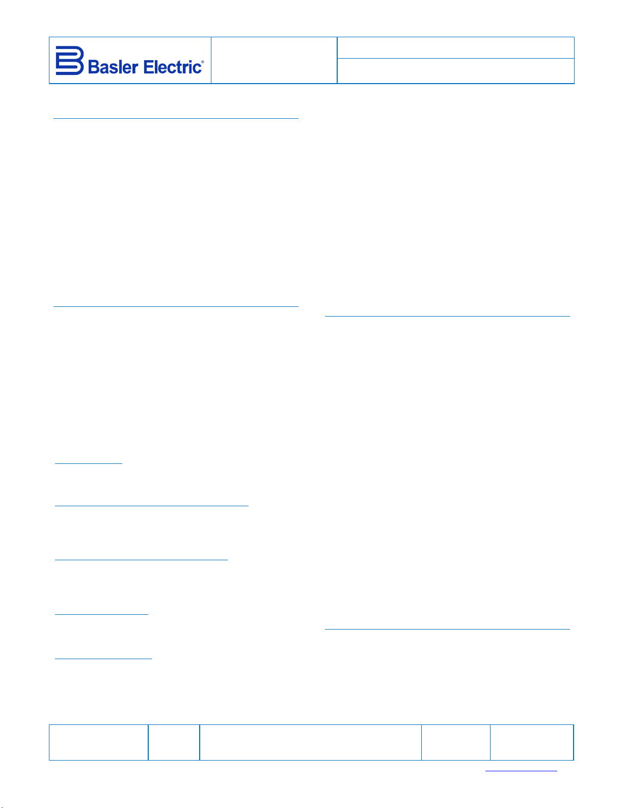
The MVC 112 Manual Voltage Control provides
manual control of field excitation during generator
startup, commissioning, or a voltage regulator failure.
The MVC 112 supplies regulated dc field power
which is adjusted by a front-panel control. An
Auto/Off/Manual switch enables transfer of control
from a voltage regulator to the MVC 112 and vice
versa. MVC 112 controls are illustrated in Figure 1.
The MVC 112 is intended for through-the-panel
mounting. All connections are made at terminal
blocks located on the rear panel. If desired, an
external potentiometer (Basler P/N 21565) may be
used for remote manual voltage adjustment.
SPECIFICATIONS
Input Power
Nominal: 120 Vac or 240 Vac, 1-phase
Operating Range
120 Vac Nominal: 90 to 153 Vac
240 Vac Nominal: 170 to 305 Vac
Frequency: 50 to 400 Hz
Dissipated Power: 35 W
Minimum Residual
Buildup Voltage: 5% of 120/240 Vac, nominal
Output Power
Current Output
12 Adc at 32 Vdc, 63 Vdc, or 125 Vdc nominal
voltage
Voltage at Maximum Potentiometer Setting
At 32 Vdc Nominal Output: 40 Vdc minimum
At 63 Vdc Nominal Output: 79 Vdc minimum
At 125 Vdc Nominal Output: 156 Vdc minimum
Minimum Acceptable Field Resistance
At 32 Vdc Nominal Output: 2.67 Ω
At 63 Vdc Nominal Output: 5.25 Ω
At 125 Vdc Nominal Output: 10.42 Ω
Regulation Accuracy
2% for a 10% change in input power
5% for a 30% change in input power
Temperature Stability
±5% for a 50C (122F) change in temperature
Environment
Operating Temperature: –40 to 70C (–40 to 158F)
Storage Temperature: –40 to 85C (–40 to 185F)
Publication
9179200990
Revision
E
Instruction
Vibration Tolerance: 2 G over a range of 10 to
500 Hz
Shock Tolerance: 15 G in each of three
perpendicular planes
Agency Compliance
EAC Mark (Eurasian Conformity)
TP TC 004/2011
TP TC 020/2011
Physical
Weight: 12 lb. (5.5 kg)
Dimensions (H, W, D): 9.63 in., 7.19 in., 7.85 in.
245 mm, 183 mm, 199 mm
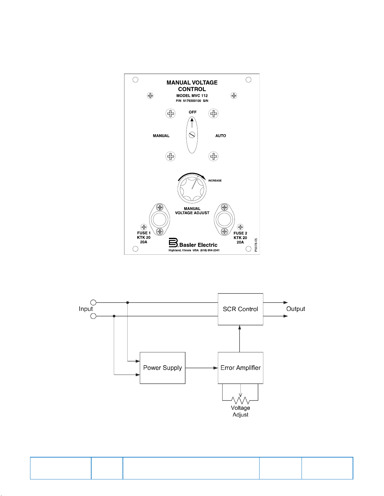
FUNCTIONAL DESCRIPTION
MVC 112 function is illustrated in Figure 2 and
described in the following paragraphs.
The MVC 112 supplies dc power to the field through
a phase-controlled SCR bridge. Adjusting the Manual
Voltage Adjust potentiometer changes the SCR firing
angle and the level of voltage applied to the field.
The MVC 112 is powered by a 120 Vac or 240 Vac
power source selected by positioning a jumper wire.
Input power frequency is also selected by a jumper.
One position selects a range of 50 to 100 hertz and a
second position selects a range of 100 to 200 hertz.
Removal of the jumper selects a range of 200 to 400
hertz.
During startup, an internal buildup circuit holds the
SCR power bridge at maximum output. When the
voltage builds to approximately 30 Vac, the buildup
circuit relinquishes control to the Manual Voltage
Adjust potentiometer.
The Auto/Off/Manual switch provides transfer control
from the voltage regulator to the MVC 112 and vice
versa. A freewheeling diode prevents arcing during
transfers.
MOUNTING
The MVC 112 is intended for through-the-panel
mounting in any location that complies with the
environmental parameters listed in the Specifications
section. It must be installed in an upright position for
maximum cooling. Overall MVC 112 dimensions are
shown in Figure 3. Panel cutting and drilling
Date
04/15
Copyright
2015
For terms of service relating to this product and software, see the Commercial Terms of Products and Servicesdocument available at www.basler.com/terms.
Page 2

s
dimensions are illustrated in Figure 4. All dimensions
are shown in inches with millimeters in parenthesis.
CONNECTIONS
Typical MVC 112 connections are shown in Figure 5.
When making connections, 14 AWG or 12 AWG wire
should be used. Torque applied to the terminal
screws should not exceed 9 inch-pounds (1 newton
meter).
Input Power Configuration
Input power voltage and frequency values are
configured by positioning jumper wires on the
MVC 112 terminal blocks.
A nominal input power voltage of 120 Vac or 240 Vac
is selected by connecting a jumper across either the
“Tap” and “120” terminals or the “Tap” and “240”
terminals.
The MVC 112 is configured for an input power
frequency within the range of 50 hertz to 100 hertz by
connecting a jumper across the “50-100” and “Com”
terminals. A frequency range of 100 hertz to 200
hertz is selected by connecting a jumper across the
“100-200” and “Com” terminals. For a frequency
within the range of 200 hertz to 400 hertz, no jumper
is connected.
Field Output Configuration
A nominal output (field) voltage of 32 Vdc, 63 Vdc, or
125 Vdc is selected through connection of a jumper
wire across the “Com” and “32”, “63”, or “125”
terminals.
External Potentiometer Connections
If a remote potentiometer will be used for control of
the MVC 112 output, the wires of the internal
potentiometer must be disconnected from terminals
14, 15, and 16. Then, the remote potentiometer is
connected with the potentiometer wiper arm
connected at terminal 15. A 10 kΩ, 1 watt
potentiometer (Basler P/N 21565) should be used.
OPERATION
generator output with the voltage regulator. Complete
excitation shutdown occurs when the switch is placed
in the Off position.
Startup
The following steps are provided as a guide for
generator startup with the MVC 112.
1. Start the prime mover and adjust the Manual
Voltage Adjust control to the minimum (fully
counterclockwise) position.
2. Place the Auto/Off/Manual switch in the Manual
position. Allow the generator terminal voltage to
build. Note that the generator voltage may be
unstable (hunting) if the Manual Voltage Adjust
control is set below 30 Vac.
3. Use the Manual Voltage Adjust control to slowly
increase the generator terminal voltage until it
reaches the desired level.
MAINTENANCE AND TROUBLESHOOTING
No preventative maintenance is required other than
periodic inspections to ensure that the MVC 112 is
free of accumulations of dirt and moisture. Verify that
all connections are clean, tight, and free of corrosion.
Operational Test Procedure
Proper MVC 112 operation can be verified with the
following procedure if faulty operation is suspected. A
voltage regulator is not required for MVC 112 testing.
1. Connect the MVC 112 as shown in Figure 6.
Place the field voltage jumper in the 125 Vdc
position (across terminals “Com” and “125”).
Place the input frequency jumper in the
appropriate position for the applied input power.
2. Adjust the Manual Voltage Adjust control fully
counterclockwise and apply 120 Vac power to the
MVC 112.
3. Slowly rotate the Manual Voltage Adjust control
clockwise and observe that the brightness of the
light bulb increases proportionally until reaching
full brightness.
Warning!
When the MVC 112 Auto/Off/Manual switch is
placed in the Manual or Off position, some
voltage regulator terminals remain connected
to the generator and present a potential shock
hazard.
With the Auto/Off/Manual switch in the Manual
position, the voltage regulator is removed from the
circuit and the generator output voltage is manually
controlled by the Manual Voltage Adjust control. The
Auto position enables automatic control of the
Publication
9179200990
Revision
E
Instruction
4. Rotate the Manual Voltage Adjust control fully
counterclockwise and remove the 120 Vac input
power.
5. Place the field voltage jumper in the 63 Vdc
position (across terminals “Com” and “63”).
6. Slowly rotate the Manual Voltage Adjust control
clockwise and observe that the brightness of the
light bulb increases proportionally until reaching
only half the brightness obtained in step 3.
7. Rotate the Manual Voltage Adjust control fully
counterclockwise and remove the 120 Vac input
power.
Date
04/15
Page
2 of 8
Page 3
s
8. Place the field voltage jumper in the 32 Vdc
position (across terminals “Com” and “32”).
9. Slowly rotate the Manual Voltage Adjust control
clockwise and observe that the brightness of the
light bulb increases proportionally until reaching
half the brightness obtained in step 6.
Figure 1. MVC 112 Front Panel Controls
Figure 2. MVC 112 Function Block Diagram
Publication
9179200990
Revision
E
Instruction
Date
04/15
Page
3 of 8
Page 4

s
Figure 3. MVC 112 Outline Dimensions
Publication
9179200990
Revision
E
Instruction
Date
04/15
Page
4 of 8
Page 5

s
Publication
9179200990
Revision
E
Figure 4. MVC 112 Panel Cutting and Drilling Diagram
Instruction
Date
04/15
Page
5 of 8
Page 6

s
Publication
9179200990
Revision
E
Figure 5. Typical MVC 112 Connections
Instruction
Date
04/15
Page
6 of 8
Page 7

s
Publication
9179200990
Revision
E
Figure 6. MVC 112 Operational Test Connections
Instruction
Date
04/15
Page
7 of 8
Page 8

s
Publication
9179200990
Revision
E
Instruction
Date
04/15
Page
8 of 8
 Loading...