

Page 1
FOR
MANUAL VOLTAGE CONTROL
MVC 104, MVC 108, AND MVC 232
INTRODUCTION
The Manual Voltage Control (MVC 104, MVC 108, or
MVC 232) allows the output voltage of a generator to
be controlled manually or automatically and provides
a means for system voltage shutdown. The Manual
Voltage Control (MVC) is designed for use with Basler
Electric automatic voltage regulators in brushless
exciter applications.
MVC components are housed in a rugged metal case
that may be door- or panel-mounted.
SPECIFICATIONS
MVC electrical and physical specifications are listed in
the following paragraphs.
Input Power (Single-Phase)
Nominal Input Voltage ∗
MVC 104: 120 Vac, 50 to 400 Hz
MVC 108: 240 Vac, 50 to 400 Hz
MVC 232: 60 Vac, 50 to 400 Hz
∗ When the generator voltage does not match the
nominal input values listed, an isolation transformer must be used. See Figure 5 for the
isolation transformer connections.
Maximum Burden
MVC 104: 840 VA
MVC 108: 1,680 VA
MVC 232: 1,200 VA
Output Power (Maximum Continuous)
MVC 104: 110 Vdc, 7 Adc
MVC 108: 220 Vdc, 7 Adc
MVC 232: 55 Vdc, 20 Adc
Physical Specifications
Operating Temperature: –40 to 50°C (–40 to 122°F)
Weight
MVC 104: 29 lb (13.2 kg)
MVC 108 and 232: 36 lb (16.3 kg)
Agency Recognition
MVC 104 and MVC 108 certified per CSA Standard
CAN/CSA-C22.2, No. 14.
MVC COMPONENTS
Manual Voltage Control components include a threeposition switch, a variable autotransformer, a full-wave
rectifier bridge, and fuses.
OPERATION
NOTE
The MVC autotransformer must be set at zero
(fully counterclockwise position) before placing the
three-position switch in the Manual position.
When the three-position switch is placed in the
Manual position, the automatic voltage regulator is
removed from the line and the generator voltage is
controlled by the MVC. The variable autotransformer
and rectifier bridge of the MVC supply a user-selected
level of dc power to the exciter field. The dc output of
the MVC is determined by the position of the autotransformer, the exciter and generator parameters,
and load conditions.
When the three-position switch is placed in the Auto
position, the generator voltage is controlled by the
automatic voltage regulator.
Complete system shutdown occurs when the threeposition switch is placed in the Off position.
With the three-position switch in either the Off or
Manual position, all automatic voltage regulator
terminals are rendered “maintenance safe” and the
regulator may be removed from the system.
OVERLOAD PROTECTION
Overload protection in Manual and Auto modes is
provided by two fuses. These fuses provide overload
protection for both the MVC and the voltage regulator.
MOUNTING
The MVC legend plate can be removed for front panel
mounting.
Panel drilling dimensions are illustrated in Figure 1.
Outline dimensions for the MVC 104, MVC 108, and
MVC 232 are shown in Figure 2.
CONNECTIONS
Typical MVC connections are illustrated in Figures 3
and 4.
When the generator voltage does not match the
nominal input values listed in Table 1, an isolation
transformer must be used. Figure 5 illustrates the
isolation transformer connections.
Table 2 lists the recommended wire sizes for MVC
connections.
903700099X
Publication
Revision
B
First Printing: 11/73
Revised: 01/07
Copyright
2007
Page 2
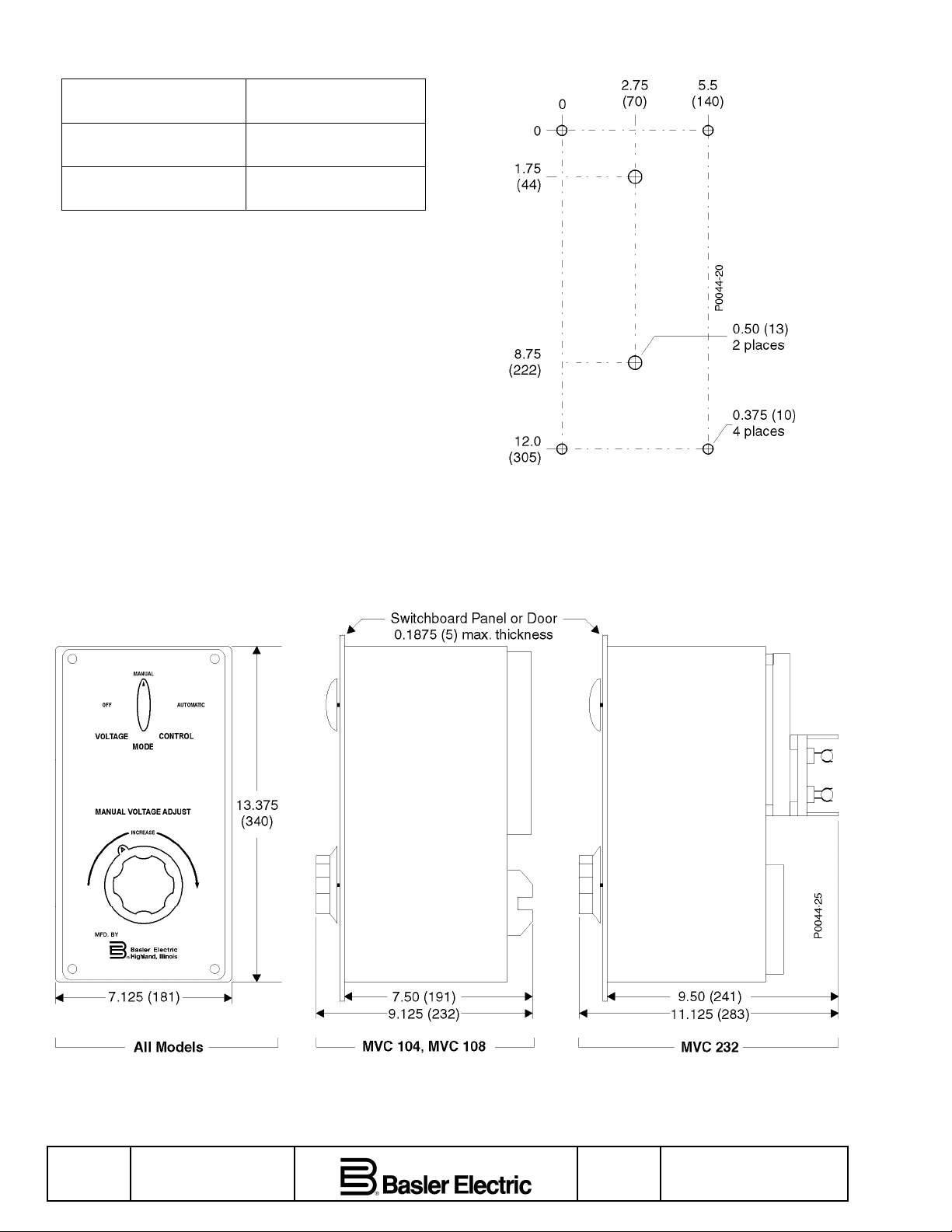
Table 2. Recommended Wire Sizes
Recommended
Terminal
L1, L2, L3, E1, E2, E3,
Wire Size
14 AWG
1, and 2
F1, F2, F+, F–, 3, 4, 23,
12 AWG
and 24
MVC terminal and fuse locations are illustrated in
Figure 6.
Figure 1. Panel Drilling Dimensions
Page 2 First Printing: 11/73
Revised: 01/07
Figure 2. Outline Dimensions
Revision
B
Publication
903700099X
Page 3

Figure 3. Typical Connections, SR Voltage Regulator
Publication
903700099X
Figure 4. Typical Connections, KR Voltage Regulator
Revision
B
First Printing: 11/73
Revised: 01/07
Page
3
Page 4

Figure 5. Isolation Transformer Connections
Page 4 First Printing: 11/73
Revised: 01/07
Figure 6. Terminal and Fuse Locations
Revision
B
Publication
903700099X
 Loading...