

Page 1
INSTRUCTION MANUA L
FOR
IDP-800
Interactive Display Panel
For use with DECS-200, DECS-200N,
DECS-250, DECS-250N, or DECS-400
Digital Excitation Control Systems
Publication: 9437600990
Revision: F Feb-15
Page 2

Page 3

9437600990 Rev F i
Caution
Note
Preface
This instruction manual provides information about the installation and operatio n of the IDP-800. To
accomplish this, the following information is provided:
• Mounting and connections
• Communication requirements
• Display operation and screen navigation
• Product specifications
Conventions Used in this Ma nua l
Important safety and procedural information is emphasized and presented in this manual through
Warning, Caution, and Note boxes. Each type is illustrated and defined as follows.
Warning!
Warning boxes call attention to conditions or actions that may cause
personal injury or death.
Caution boxes call attention to operating conditions that may lead to
equipment or property damage.
Note boxes emphasize important information pertaining to IDP-800
installation or operation.
IDP-800 Preface
Page 4
ii 9437600990 Rev F
Basler Electric does not assume any responsibility to compliance or noncompliance with national code, local code,
For terms of service relating to this product and software, see the Commercial Terms of Products and Services
document available at www.basler.com/terms.
This publication contains confidential information of Basler Electric Company, an Illinois corporation. It is loaned for
and options are subject to modification without notice. Over time, improvements and revisions may be made to this
manual.
The English-language version of this manual serves as the only approved manual version.
12570 State Route 143
Highland IL 62249-1074 USA
www.basler.com
info@basler.com
Tel: +1 618.654.2341
Fax: +1 618.654.2351
© 2015 by Basler Electric
All rights reserved
First printing: February 2010
Warning!
READ THIS MANUAL. Read this manual before installing, operating, or maintaining the IDP-800. Note
all warnings, cautions, and notes in this manual as well as on the product. Keep this manual with the
product for reference. Failure to follow warning and cautionary labels may result in personal injury or
property damage. Exercise caution at all times.
To prevent personal injury or equipment damage, only qualified personnel should install, operate, or
service this system.
or any other applicable code. This manual serves as reference material that must be well understood prior to
installation, operation, or maintenance.
confidential use, subject to return on request, and with the mutual understanding that it will not be used in any
manner detrimental to the interests of Basler Electric Company and used strictly for the purpose intended.
It is not the intention of this manual to cover all details and variations in equipment, nor does this manual provide
data for every possible contingency regarding installation or operation. The availability and design of all features
publication. Before performing any of the following procedures, contact Basler Electric for the latest revision of this
Preface IDP-800
Page 5

9437600990 Rev F iii
Contents
Introduction ................................................................................................................................................. 1
IDP-800 Style Designations ...................................................................................................................... 1
Communication ........................................................................................................................................... 3
Ethernet Communication ........................................................................................................................... 4
IDP-800-A Operation ................................................................................................................................... 7
Main View Screen ...................................................................................................................................... 8
Generator/Motor Monitor ........................................................................................................................... 9
DECS Metering Screen ........................................................................................................................... 10
DECS Control .......................................................................................................................................... 13
Alarms and Status ................................................................................................................................... 15
IDP-800-B Operation ................................................................................................................................. 17
Configuration Screens ............................................................................................................................. 17
Main View Screen .................................................................................................................................... 19
Generator/Motor Monitor ......................................................................................................................... 20
DECS Metering Screen ........................................................................................................................... 21
DECS Control .......................................................................................................................................... 23
Alarms and Status ................................................................................................................................... 25
IDP-800-C Operation ................................................................................................................................. 29
Configuration Screens ............................................................................................................................. 29
Main View Screen .................................................................................................................................... 30
DECS Metering Screen ........................................................................................................................... 32
Modbus™ Communication....................................................................................................................... 43
IDP-800 Register Table ........................................................................................................................... 43
Mounting .................................................................................................................................................... 49
Mounting of Accessories ......................................................................................................................... 51
Connections .............................................................................................................................................. 53
Control Power Connections ..................................................................................................................... 54
Communication Connections .................................................................................................................. 54
Maintenance and Troubleshooting ......................................................................................................... 57
Troubleshooting ....................................................................................................................................... 57
Specifications ............................................................................................................................................ 59
Revision History ........................................................................................................................................ 61
IDP-800 Contents
Page 6

iv 9437600990 Rev F
Contents IDP-800
Page 7
9437600990 Rev F 1
Introduction
The IDP-800 Interactive Display Panel is a high-resolution, 7.5 inch/19 centimeter (measured diagonally)
color touch screen interface that enables a user to monitor and control a Basler Electric DECS-based
excitation system. IDP-800 monitoring and control features include DECS and excitation system status,
system control operations, and routine adjustments of the excitation setpoint. The IDP-800 is compatible
with DECS-200, DECS-200N, DECS-250, DECS-250N, and DECS-400 Digital Excitation Control
Systems.
DECS and synchronous generator or motor system parameters are viewed and controlled through
interactive pages displayed by the IDP-800. Pages are organized according to system functions.
Navigation between pages and control of functions is achieved by touching buttons located on the IDP800 pages.
Communication between the IDP-800 and DECS is facilitated through the serial communication port of
the IDP-800 and the RS-485 port of the DECS. One IDP-800 can monitor both the primary and secondary
DECS in a dual DECS application. The IDP-800 is equipped with an Ethernet communication port which
provides access to Modbus™ registers for system monitoring and control of the DECS. This capability
enables integration of the IDP-800 into an existing Distributed Control System (DCS).
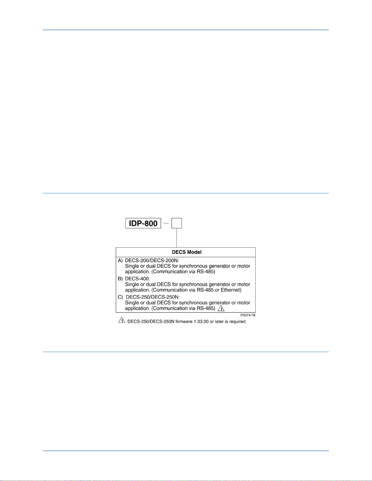
IDP-800 Style Designations
A single-digit style designator determines the DECS application that is compa tib le with the IDP-800. Style
options are shown in Figure 1.
Figure 1. IDP-800 Style Options
Hardware
The IDP-800 is supplied with the following hardware:
• Compact flash memory card
• Terminal conversion adaptor
• Two 680 Ω terminating resistors with sleeving
• Instruction manual (Basler publication 9437600990)
Accessories
The following optional accessories are available for use with the IDP-800:
• Power supply, 24 Vdc, 31 W, Basler P/N 933450310 1
• Ethernet switch, 8 ports, Basler P/N 41133
• DIN mounting rail for Ethernet switch, Basler P/N 9323900001
IDP-800 Introduction
Page 8

2 9437600990 Rev F
Introduction IDP-800
Page 9

9437600990 Rev F 3
Controller Application
{Communication Scheme}
Local Only
Only
Remote †
DCS ∗
DECS-200
{Figure 2}
DECS-200N
{Figure 2}
DECS-250
{Figure 2}
DECS-250N
{Figure 2}
DECS-400
{Figure 2}
DECS-400
{Figure 3}
Communication
Data and commands can be exchanged between the IDP-800 and DECS-200, DECS-200N, DECS-250,
DECS-250N, or DECS-400 using serial communication. In addition to serial communication, the DECS400 has the added capability of Ethernet communication with the IDP-800. When connected to an
Ethernet LAN, the display can be polled via Modbus to acquire data collected by the DECS-400
connected to the IDP-800.
DECS and IDP-800 communication applications are summarized in Table 1.
Table 1. DECS and IDP-800 Communication Applications
[Communication Method]
[Serial, RS-485]
[Serial, RS-485]
[Serial, RS-485]
[Serial, RS-485]
[Serial, RS-485]
[Ethernet] ‡
∗ Distributed Contr ol Sy stem ( DC S) interfac e offer s pass -through communication to/from the
DECS-200, DECS-200N, DECS-250, or DECS-250N via the IDP-800 Ethernet port.
† Requires two IDP-800 display panels.
‡ Requires a multi-port Ethernet switch between an IDP-800 and single- or dual-DECS-400
controllers. An open port on the switch enables external (DCS) control and monitoring
communication between the IDP-800 and DECS-400.
YES YES N/A YES
YES YES N/A YES
YES YES N/A YES
YES YES N/A YES
YES YES YES N/A
YES YES YES YES
Remote
Local and
Serial Communication
When the IDP-800 will be communicating with a DECS using RS-485 serial communication, the DECS
communication settings should be configured as follows:
• Baud: 9600
• Data length: 8
• Parity: None
• Stop bits: 2
• Single DECS address: 247
• Dual DECS address: 247 (DECS-A) and 246 (DECS-B)
IDP-800 Communication
Page 10
4 9437600990 Rev F
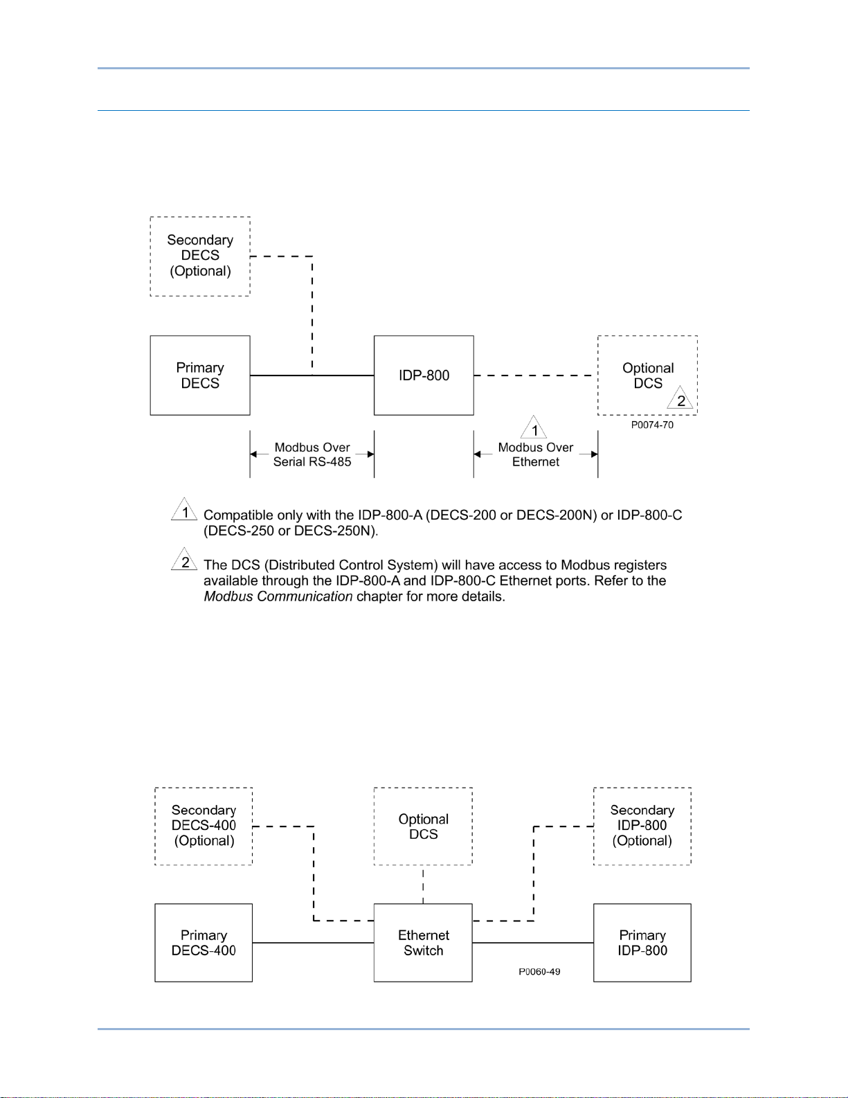
Ethernet Communication
An Ethernet port enables the IDP-800 to be polled over a LAN/Distributed Control System and provide
values of system parameters monitored by the DECS-200, DEC S-200N, DECS-250, or DECS-250N.
Figure 2 serves as a general illustration of how the IDP-800 can be used to retrieve DECS data over an
Ethernet LAN. The IDP-800-A and IDP-800-C’s 10 Base-T Ethernet interface connects to a LAN through
a standard RJ-45 modular jack. This jack is located on the bottom of the display.
Figure 2. IDP-800 Link Between DECS and Ethernet LAN
IDP-800 Modbus registers for the available DECS functions are listed in the Modbus Communication
chapter. Specific information about the Modbus communication protocol, as it is employed by the DECS,
is provided in Basler publication 9360100990 (DECS-200), 9388800990 (DECS-200N), 9440300990
(DECS-250), and 9440500990 (DECS-250N).
An Ethernet port (Com 3) on the DECS-400 enables communication with the IDP-800 at higher speeds
than possible through the DECS-400 RS-485 port. An Ethernet switch is used to route IDP-800 and
DECS-400 communication over a LAN. A general connection scheme for IDP-800 and DECS-400
communication over an Ethernet LAN is illustrated in Figure 3.
Figure 3. IDP-800 and DECS-400 LAN Communication
Communication IDP-800
Page 11

9437600990 Rev F 5
Caution
For IDP-800 polling to take place, its IP address must be configured to accommodate your Ethernet LAN.
Perform the following steps to view the IDP-800 communication settings and configure its IP address.
The following procedure must be performed with the generator or
motor offline. Communication between the IDP-800 and DECS will
cease during configuration of the IP address.
1. Press the upper, right corner of the display screen followed by the lower, left corner in quick
succession.
2. Press the Offline button.
3. When prompted, enter the offline mode access password. The factory-default password is
“basler”.
4. At the next prompt, enter the system password. The factory-default password is “4376”.
5. Press the Main Unit Settings button.
6. Press the Ethernet Local Settings button.
7. Configure the IP address to be compatible with your network. If needed, consult your network
administrator for the proper settings.
8. Press the Exit button.
9. Press the Yes button. The display will restart and activate the new communication settings.
IDP-800 Communication
Page 12

6 9437600990 Rev F
Communication IDP-800
Page 13
9437600990 Rev F 7
IDP-800-A Operation
The IDP-800-A is applied in applications using the DECS-200 and DECS-200N. The IDP-800-B is applied
in applications using the DECS-400. The IDP-800-C is applied in applications using the DECS-250 and
DECS-250N. See Figure 1 for IDP-800 style definitions. This chapter describes IDP-800-A operation and
screen navigation. For DECS-400 applications, see the IDP-800-B Operation chapter. For DECS-250 and
DECS-250N applications, see the IDP-800-B Operation chapter.
IDP-800 screen appearance and availability will vary according to the type of DECS used and the
configuration of the DECS system (single or dual DECS and generator or motor control).
DECS and generator/motor system parameters are viewed and controlled through interactive screens
displayed by the IDP-800. Screens are organized according to function. Navigation between screens and
control of functions are achieved by touching “buttons” on the IDP-800 screens.
Configuration Screens
Two configuration screens establish DECS and IDP-800 o perat ing mo des : IDP-800 Configuration and
Screen Configuration. These configuration screens are available upon initial power-up of the IDP-800.
After initial configuration, these screens can be accessed through the Main View screen by entering the
appropriate password.
IDP-800 Configuration
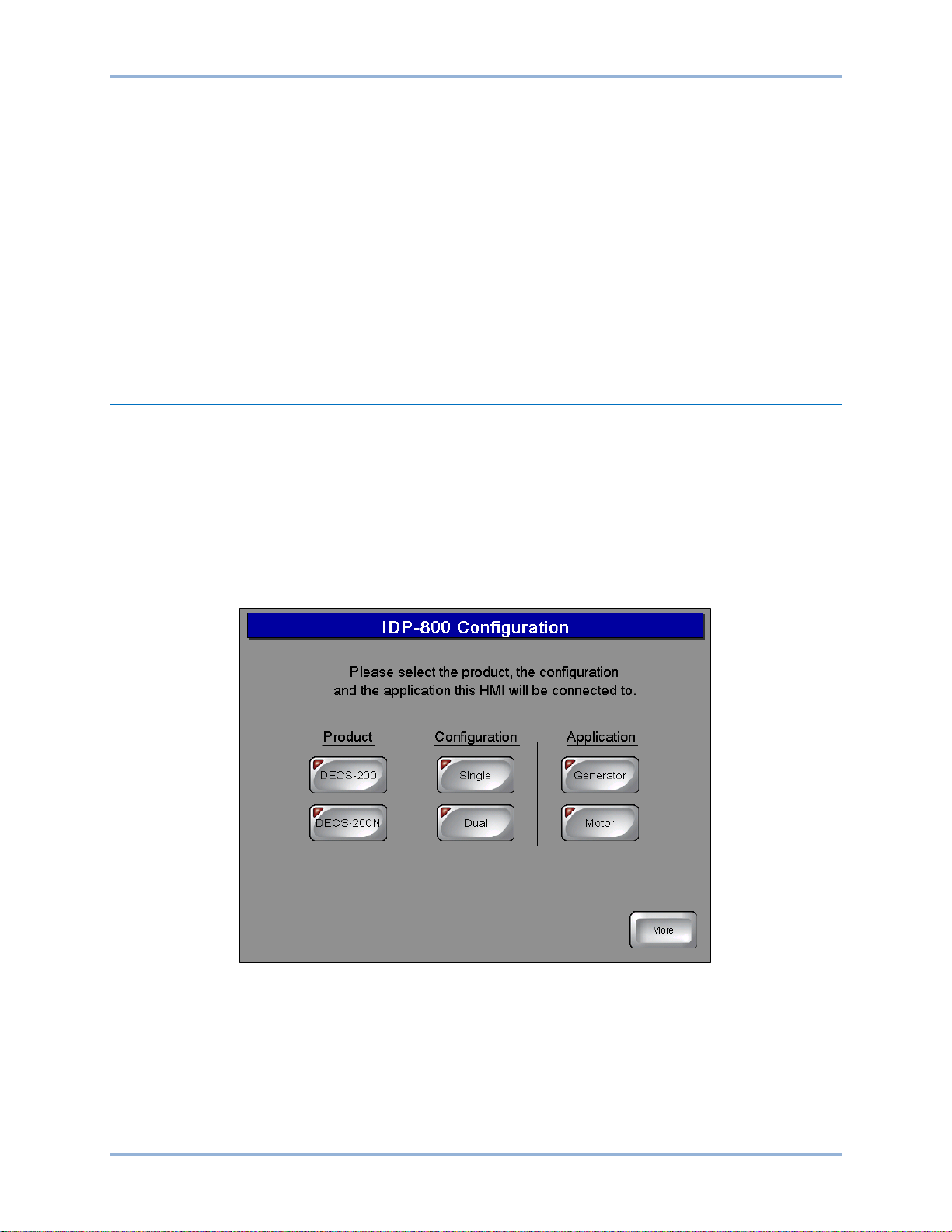
Upon initial power-up, the IDP-800 displays the IDP-800 Configuration screen (Figure 4) where your
product, product configuration, and application must be selected before proceeding to other IDP-800
screens. Failure to make the proper selections may cause the IDP-800 to annunciate false alarms.
Figure 4. IDP-800 Configuration Screen
Screen Configuration
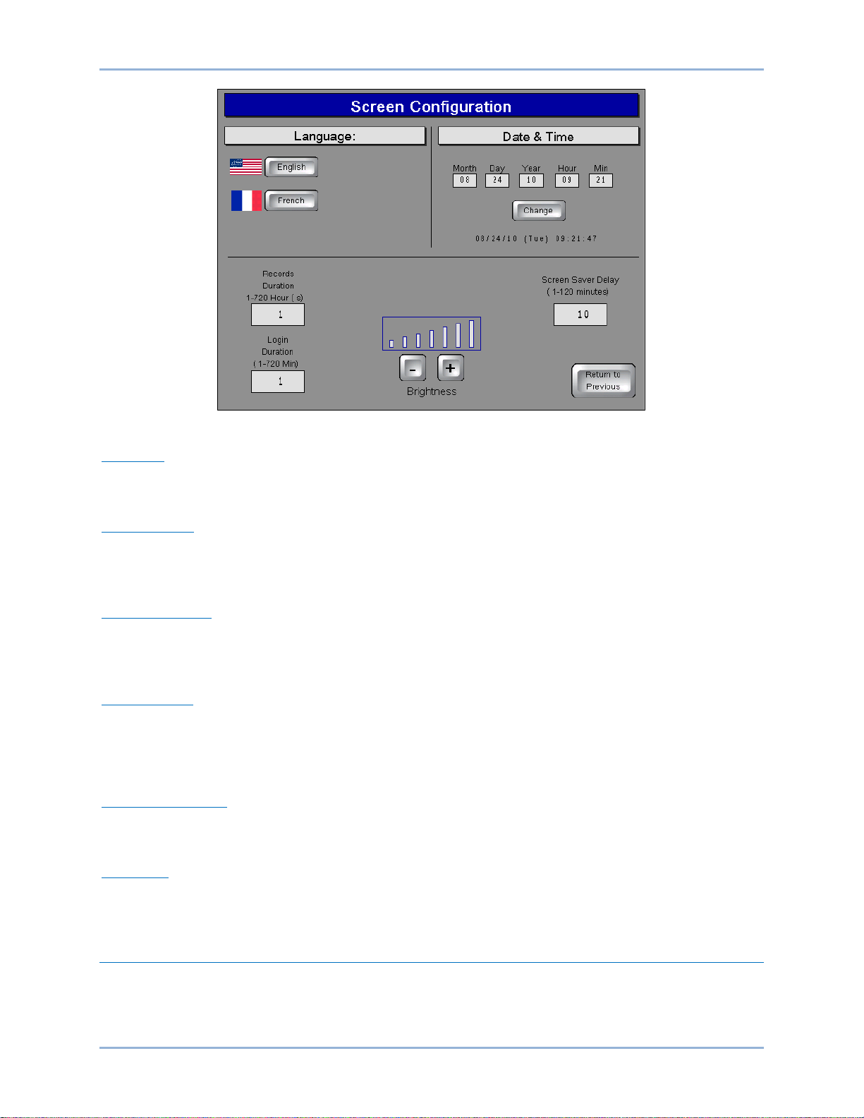
Pressing the More button on the IDP-800 Configuration screen accesses the Screen Configuration screen
(Figure 5) which enables selection of the IDP-800 language, date and time, and other IDP-800 operating
preferences. Individual screen functions are described in the following paragraphs.
IDP-800 IDP-800-A Operation
Page 14
8 9437600990 Rev F
Figure 5. Screen Configuration
Language
Pressing the English (or Anglais) button selects English as the IDP-800 disp lay language. Pressing the
French (or Francais) button selects French as the display language.
Date and Time
The date and time of the IDP-800 must be set manually to match the date and time of the connected
DECS. Enter the desired values in the date and time fields and press the Change button to save the
values.
Records Duration
Trending records saved by the IDP-800 retain up to six variables per record with each record consisting of
2,400 data points. Trending records saved by the IDP-800 can have a user-defined duration ranging from
1 hour to 720 hours (30 days). Note: requires installation of a compact flash memory card.
Login Duration
Following login, the length of time that pass wor d acc es s is available (if no butt on pres s es occ ur) is limited
by the value of this setting. If no button presses are received for the duration of the setting, password
access is lost and the user must log in again to make changes requiring password access. Login Duration
is adjustable over the range of 1 to 720 minutes (12 hours).
Screen Saver Delay
A screensaver activates if no button presses are received at the display panel for the length of time
specified by the Screen Saver Delay. A setting of 1 to 120 minutes may be entered.
Brightness
Display panel brightness can be adjusted by pressing the “+” and “–“ buttons. A bar graph above the
buttons serves as a reference for adjusting the display brightness .
Main View Screen
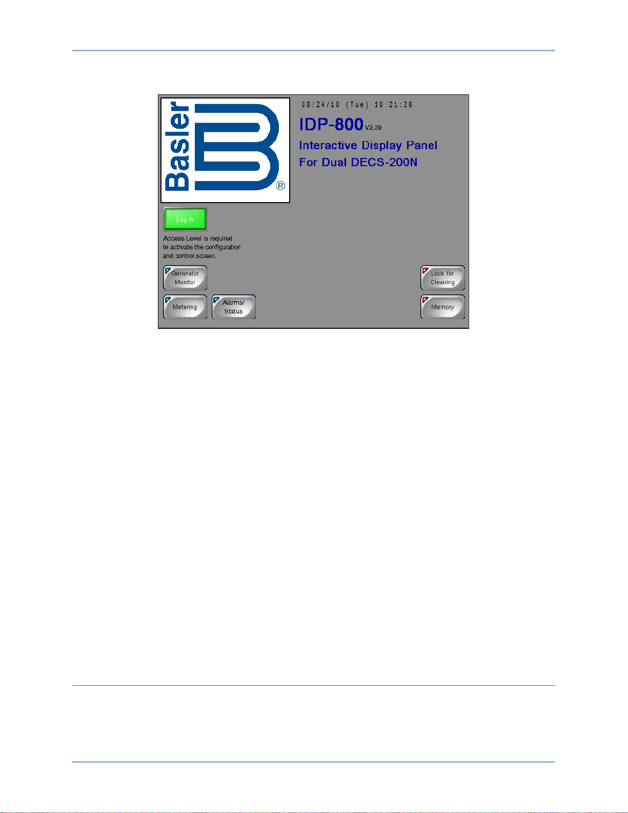
This screen (Figure 6) serves as a gateway to the IDP-800 status and control screens. It also provides
access to file transfer functions and a screen lock to enable panel cleaning. The Login button can be used
to enter the appropriate password and gain access to the configuration screens.
IDP-800-A Operation IDP-800
Page 15
9437600990 Rev F 9
Access to the control screens is possible only when logged into the IDP-800 w ith the correct password.
As a result, the Control button is visible only when logged into the IDP-800.
Figure 6. Main View Screen
IDP-800 Passwords
Four passwords protect the IDP-800 from unauthorized settings changes, control commands, and
transfers offline.
Two of the passwords are used when transferring the IDP-800 offline. When taking the IDP-800 offline,
the offline and system passwords are used. The IDP-800 is del iver ed with a system password of “4376”
and an offline mode access password of “basler”.
A factory-default password of “IDP8” gives access to IDP-800 configuration and control functions.
A factory-default password of “DECS2” gives access to only the IDP-800 control functions.
Password access remains in effect based on display panel activity and the limit set by the Login Duration
setting (Screen Configuration screen).
Gaining Password Access
The following example describes the process for using a password to gain configuration and control
access.
1. Press the Login button on the Main View screen.
2. Use the alphanumeric keypad to enter the appropriate password and press the Enter button. The
factory-default password is IDP8 and is case-sensitive.
Once the correct password is entered, the Main View screen is displayed with a Control button that
provides access to the control screens and a Configure button that provides access to the configuration
screens.
Generator/Motor Monitor
Depending upon the application selected on the IDP-800 Configuration screen, either the Generator
Monitor screen or the Motor Monitor screen is accessed by pressing the Generator Monitor button or
Motor Monitor button of the Main View screen. The Generator Monitor or Motor Monitor screen graphically
illustrates generator/motor and excitation system status/activity. Generator and motor parameters include
output voltage, output current, active (true) power, reactive power, and power factor. Excitation system
IDP-800 IDP-800-A Operation
Page 16
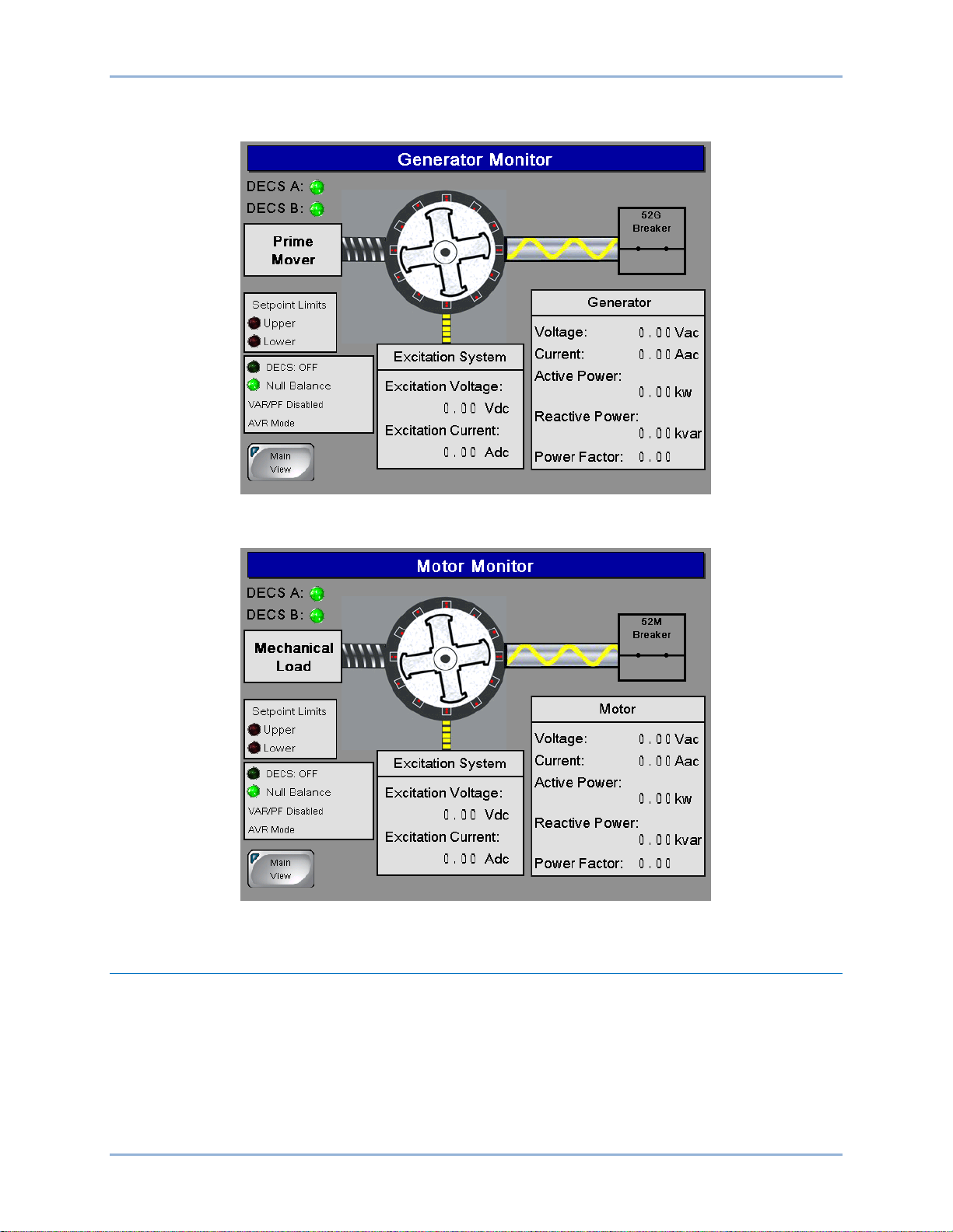
10 9437600990 Rev F
parameters include field voltage, field current, and excitation on/off status. The Generator Monitor screen
is shown in Figure 7 and the Motor Monitor screen is shown in Figure 8.
Figure 7. Generator Monitor Screen
Figure 8. Motor Monitor Screen
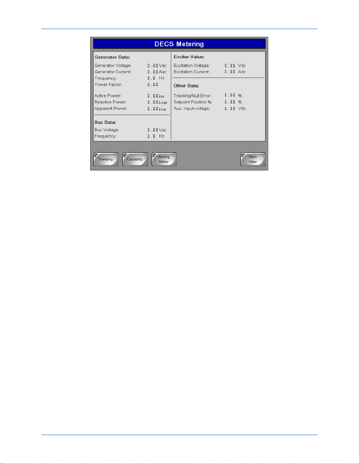
DECS Metering Screen
This screen (Figure 9) is accessed by pressing the Metering button of the Main View screen. The DECS
Metering screen displays digital metering values for the generator or motor, bus, and exciter field as well
as the excitation setpoint position and control values.
Access to the Trending and Capability Curve screens is also provided through the Trending and
Capability buttons on the DECS Metering screen.
IDP-800-A Operation IDP-800
Page 17
9437600990 Rev F 11
Figure 9. DECS Metering Screen
Analog Metering
Pressing the Analog Meter button accesses the analog representations of the digital values displayed on
the DECS Metering screen. Analog metering values are divided among three screens accessed through
buttons labeled Generator Values, Generator Power, and Exciter Values. Each p ar amet er is repres e nte d
by an analog meter along with the digital version of the metered value.
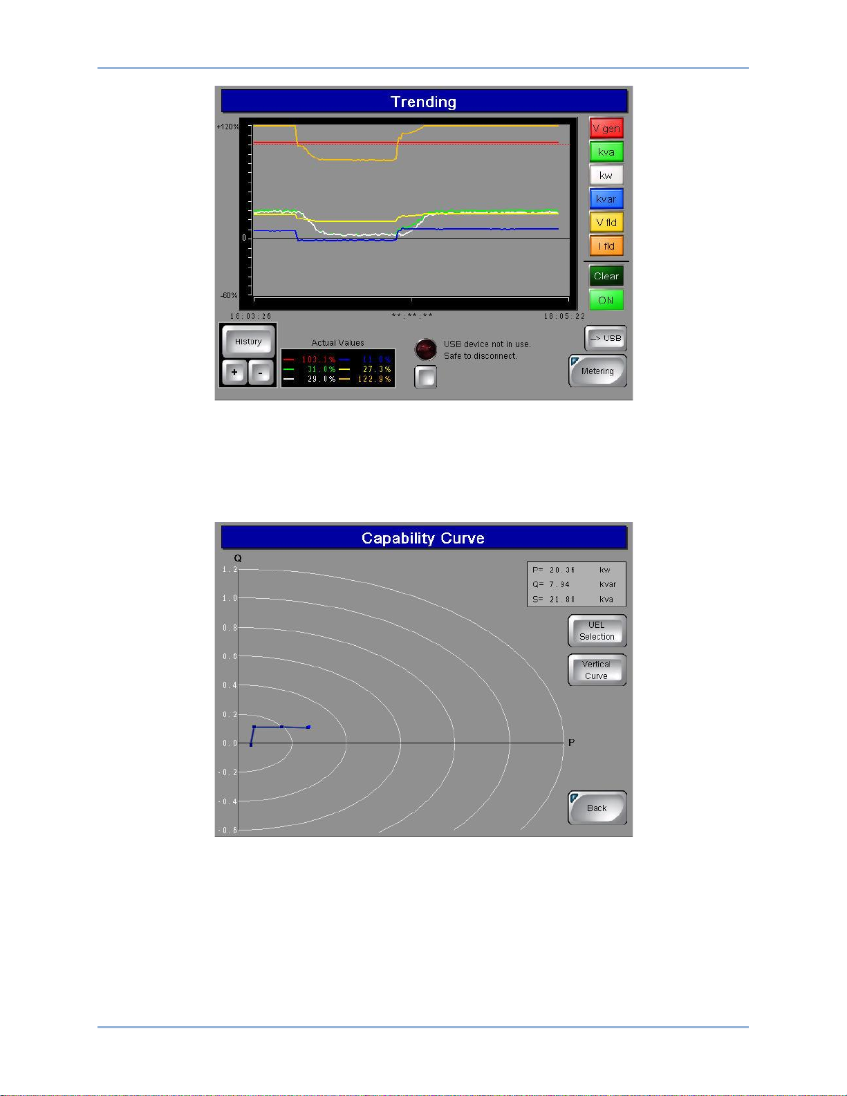
Trending
The Trending screen (Figure 10) is accessed by pressing the Trending button of the DECS Metering
screen. Several system parameters can be selected and monitored over time in an amplitude-versus-time
window. Buttons on the Trending screen enable selection of the parameters to be monitored. Available
parameters include generator voltage (Vgen), apparent power (kVA), true power (kW), reactive power
(kvar), field voltage (Vexc), and field current (Iexc). Parameters are plotted in a color that matches the
color of the parameter buttons. Pressing the History button displays additional controls and a display for
manipulating the cursor position within a data plot. Pressing the USB button transfers the trending data to
a connected USB memory device. Storage of trending information requires the installation of a compact
flash memory card.
IDP-800 IDP-800-A Operation
Page 18
12 9437600990 Rev F
Figure 10. Trending Screen
Capability
This screen (Figure 11) is accessed by pressing the Capability button on the DECS Metering screen. By
default, a horizontal curve is displayed. Pressing the Vertical Curve button selects a vertical curve
orientation.
Figure 11. Capability Curve Screen
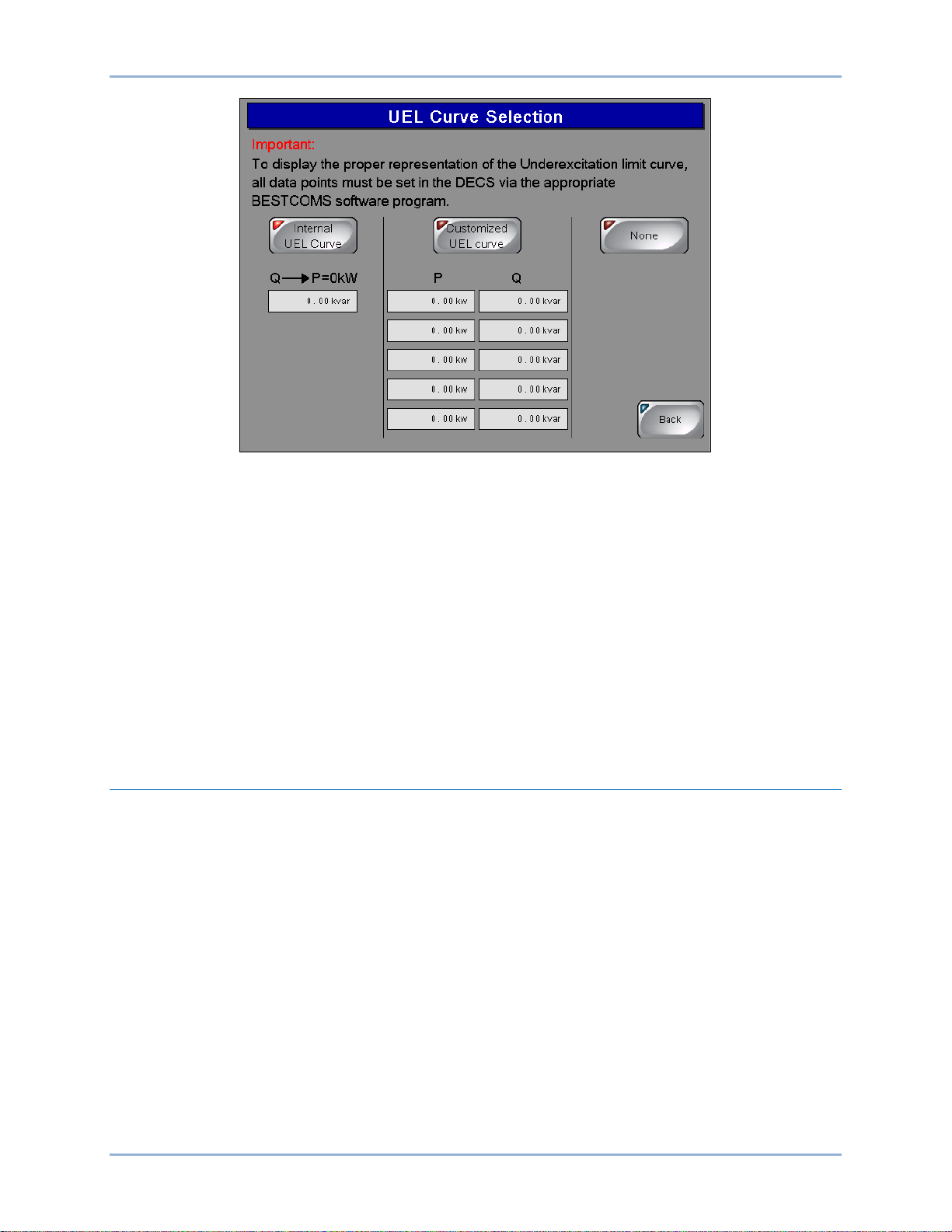
If a plot of the underexcitation limiter (UEL) curve is desired, the UEL Selection button can be pressed to
access the UEL Curve Selection screen (Figure 12). Here, the internal DECS UEL curve can be selected
or a customized, three-point, four-point, or five-point curve can be selected and configured. UEL curve
points must be selected in the DECS BESTCOMS software for an accurate representation on the
IDP-800. Pressing the None button disables the display of UEL curves.
IDP-800-A Operation IDP-800
Page 19
9437600990 Rev F 13
Figure 12. UEL Curve Selection Screen
DECS Analog Metering
Analog representations of the digital metering values shown on the DECS Metering screen (Figure 9) can
be accessed by pressing the Analog Meter button. Pressing this button accesses the Generator Values or
Motor Values screen which displays analog representations of the generator/motor voltage, current,
frequency, and power factor. Each analog representation displays the digital equivalent in the upper, left
corner. The remaining analog metering values are divided between two screens: the Generator Power or
Motor Power screen and the Exciter values screen. The Generator Power or Motor Power screen is
accessed from the Generator/Motor Values screen or Exciter Values screen by pressing the Generator
Power or Motor Power button. This screen displays analog representations of the generator/motor active
power, reactive power, and apparent power. The Exciter Values screen is accessed from the
Generator/Motor Values screen or Generator/Motor Power screen by pressing the Exciter Values butt on.
This screen displays analog representations of the excitation voltage and current. A Digital Meter button,
on each analog metering screen, can be pressed to return to the DECS (digital) Metering screen.
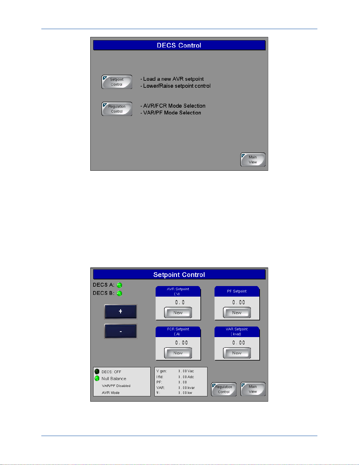
DECS Control
Access to the DECS Control screen is possible only when logged in with the appropriate password. When
logged in, a Control button on the Main View screen provides access to the DECS Control screen
illustrated in Figure 13. DECS control functions are divided between two screens: Setpoint Control and
Regulation Control.
IDP-800 IDP-800-A Operation
Page 20
14 9437600990 Rev F
Figure 13. DECS Control Screen
Setpoint Control
Pressing the Setpoint Control button accesses the Setpoint Control screen (Figure 14). This screen
displays the DECS-200/200N AVR, FCR, power factor, and var setpoints and provides two methods of
setpoint adjustment. The “+” and “–“ buttons can be pressed to increment and decrement the active
setpoint. A specific setpoint can be entered for any of the four setpoints. Pressing the New button
associated with the setpoint to be changed accesses a Setpoint Adjustment screen that displays the
current setpoint value along with the minimum and maximum limits for the setting. Touching the setting
field area displays a numeric keypad where the new value can be entered.
The Setpoint Control screen also has system status indicators and a metering display for generator and
excitation system parameters.
Figure 14. Setpoint Control Screen
IDP-800-A Operation IDP-800
Page 21
9437600990 Rev F 15
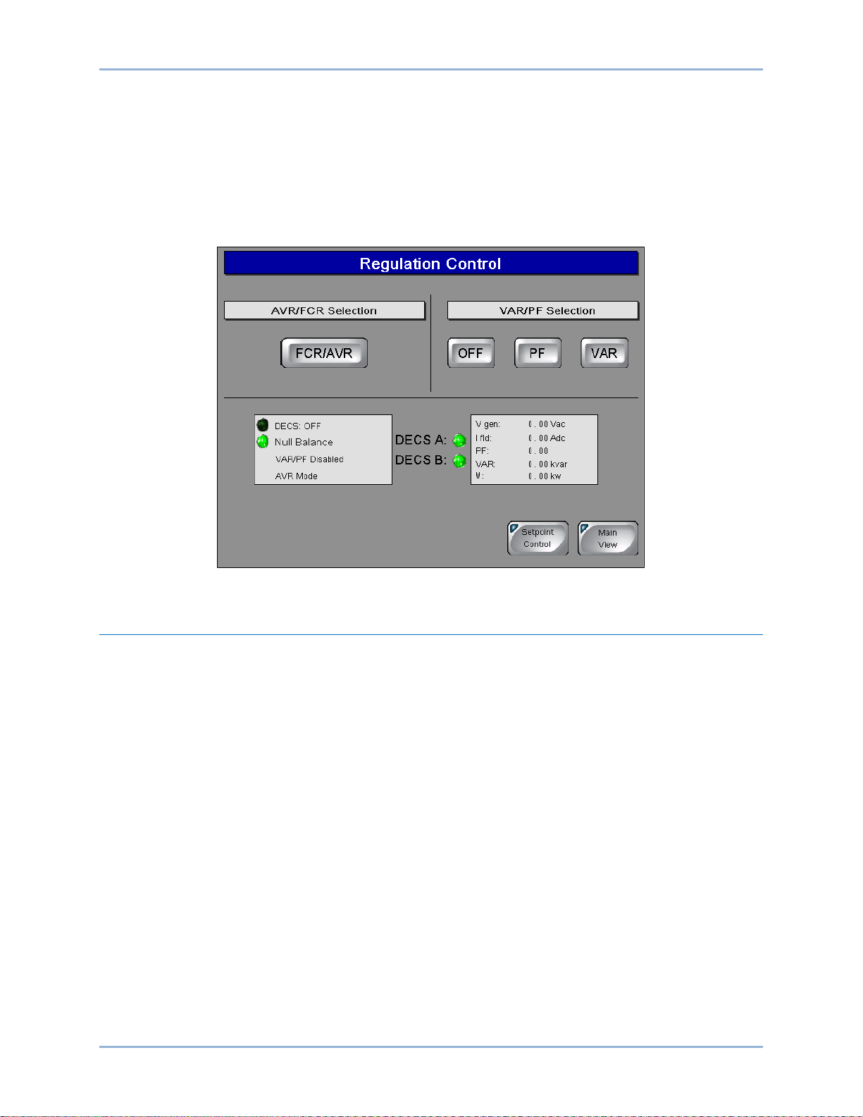
Regulation Control
Pressing the Regulation Control button accesses the Regulation Control screen (Figure 15). This screen
enables selection of the active regulation mode. The MAN/AVR button toggles between Manual and Auto
modes. When operating in AVR mode, the Off, PF, and VAR buttons can be used to enable or disable
regulation of vars or power factor. Each change to the regulation mode requires a confirmation via an
accept/reject dialog box.
The Regulation Control screen also has system status indicators and a metering display for
generator/motor and excitation system parameters.
Figure 15. Regulation Control Screen
Alarms and Status
Two screens annunciate the state of DECS alarms, functions, limiters, and relay outputs. Depending upon
the annunciation, active indicators change to amber, green, or red when active.
Pressing the Alarms/Status button of the Main View screen displays the Alarms and Status screen (Figure
16). This screen has indicators for alarms, limiter states, and DECS functions/conditions. An Alarms
Reset button can be pressed to clear alarm annunciations. (An alarm cannot be reset unless the condition
causing the alarm has been cleared.) Pressing the History button accesses the Alarms History screen
which lists the alarms captured by the DECS. Buttons are provided for scrolling through the alarms list,
clearing selected alarms, and clearing all listed alarms. A USB button enables the transfer of selected
alarm records to a memory device plugged into the IDP-800 U SB po rt .
IDP-800 IDP-800-A Operation
Page 22

16 9437600990 Rev F
Figure 16. Alarms and Status Screen
Pressing the Relay Status button on the Alarms and Status screen displays the DECS Relay Status
screen (Figure 17). This screen has indicators for DECS relay output contacts status (open or closed) and
a matrix of indicators showing each relay output and the condition causing the relay output to energize.
Pressing the Back button returns the display to the Alarms and Status screen.
Figure 17. DECS Relay Status Screen
IDP-800-A Operation IDP-800
Page 23

9437600990 Rev F 17
IDP-800-B Operation
The IDP-800-B is applied in applications using the DECS-400. The IDP-800-A is applied in applications
using the DECS-200 and DECS-200N. The IDP-800-C is applied in applications using the DECS-250 and
DECS-250N. See Figure 1 for IDP-800 style definitions. This chapter describes IDP-800-B operation and
screen navigation. For DECS-200 and DECS-200N applications, see the IDP-800-A Operation chapter.
For DECS-250 and DECS-250N applications, see the IDP-800-C Operation chapter.
IDP-800 screen appearance and availability will vary according to the type of DECS used and the
configuration of the DECS system (single or dual DECS and generator or motor control).
DECS and generator/motor system parameters are viewed and controlled through interactive screens
displayed by the IDP-800. Screens are organized according to function. Navigation between screens and
control of functions are achieved by touching “buttons” on the IDP-800 screens.
Configuration Screens
Two configuration screens establish DECS and IDP-800 o perat ing mo des : IDP-800 Configuration and
Screen Configuration. These configuration screens are available upon initial power-up of the IDP-800.
After initial configuration, these screens can be accessed through the Main View screen by entering the
appropriate password.
IDP-800 Configuration
Upon initial power-up, the IDP-800 displays the IDP-800 Configuration screen (Figure 18) where your
product, product configuration, application, and communication method must be selected before
proceeding to other IDP-800 screens. Failure to make the proper selections may cause the IDP-800 to
annunciate false alarms.
Figure 18. IDP-800 Configuration Screen
Screen Configuration
Pressing the More button on the IDP-800 Configuration screen accesses the Screen Configuration screen
(Figure 19) which enables selection of the IDP-800 language and other operating preferences. Individual
screen preferences are described in the f ol low ing para gr aphs.
IDP-800 IDP-800-B Operation
Page 24

18 9437600990 Rev F
Language
Pressing the English (or Anglais) button selects English as the IDP-800 disp lay language. Pressing the
French (or Francais) button selects French as the display language.
Date and Time
The date and time of an IDP-800 connected to a DECS-400 is automatically synchronized with the date
(month, day, and year) and time (hours and minutes) maintained by the DECS-400.
52L/M Input Switch Number
These buttons configure the IDP-800 to monitor the same contact inputs that the DECS-400 is monitoring
for the 52L/M contact input. Pressing the Standard Logic button configures the IDP-800 to monitor contact
input 3 for 52L/M contact status, which is the default assignment in standard DECS-400 logic. Pressing
the Customized Logic button enables the user to configure the IDP-800 to monitor the 52L/M contact
input as configured in the customized DECS-400 logic.
Records Duration
Trending records saved by the IDP-800 retain up to six variables per record with each record consisting of
2,400 data points. Trending records saved by the IDP-800 can have a user-defined duration ranging from
1 hour to 720 hours (30 days). Note: requires installation of a compact flash memory card.
Figure 19. Screen Configuration Screen
Login Duration
Following login, the length of time that pass wor d acc es s is available (if no butt on pres s es occ ur) is limited
by the value of this setting. If no button presses are received for the duration of the setting, password
access is lost and the user must log in again to make changes requiring password access. Login Duration
is adjustable over the range of 1 to 720 minutes (12 hours).
Screen Saver Delay
A screensaver activates if no button presses are received at the display panel for the length of time
specified by the Screen Saver Delay. A setting of 1 to 120 minutes may be entered.
Brightness
Display panel brightness can be increased and reduced by pressing the “+” and “–“ buttons. A bar graph
above the buttons serves as a reference for adjusting the display brightness.
IDP-800-B Operation IDP-800
Page 25

9437600990 Rev F 19
Main View Screen
This screen (Figure 20) serves as a gateway to the IDP-800 status and control screens. It also provides
access to file transfer functions and a screen lock to enable panel cleaning. The Login button can be used
to enter the appropriate password and gain access to the configuration screens.
Figure 20. Main View Screen
Access to the Control button (and control screens) is possible only when logged into the IDP-800 with the
correct password.
IDP-800 Passwords
Four passwords protect the IDP-800 from unauthorized settings changes, control commands, and
transfers offline.
Two of the passwords are used when transferring the IDP-800 offline. When taking the IDP-800 offline,
the offline and system passwords are used. The IDP-800 is delivered with a system password of “4376”
and an offline mode access password of “basler”.
A factory-default password of “IDP8” gives access to IDP-800 configuration and control functions.
A factory-default password of “DECS4” gives access to only the IDP-800 control functions.
Password access remains in effect based on display panel activity and the limit set by the Login Duration
setting (Screen Configuration screen).
Gaining Password Access
The following example describes the process for using a password to gain configuration and control
access.
1. Press the Login button on the Main View screen.
2. Use the alphanumeric keypad to enter the appropriate password and press the Enter button. The
factory-default password is IDP8 and is case-sensitive.
Once the correct password is entered, the Main View screen is displayed with a Control button that
provides access to the control screens and a Configure button that provides access to the configuration
screens.
IDP-800 IDP-800-B Operation
Page 26

20 9437600990 Rev F
Generator/Motor Monitor
Depending upon the application selected on the IDP-800 Configuration screen, either the Generator
Monitor screen or Motor Monitor screen is accessed by pressing the Generator Monitor button or Motor
Monitor button of the Main View screen. The Generator Monitor or Motor Monitor screen graphically
illustrates generator/motor and excitation system status/activity. Generator and motor parameters include
output voltage, output current, active (true) power, reactive power, and power factor. Excitation system
parameters include field voltage, field current, and excitation on/off status. The Generator Monitor screen
is shown in Figure 21 and the Motor Monitor screen is shown in Figure 22.
Figure 21. Generator Monitor Screen
Figure 22. Motor Monitor Screen
IDP-800-B Operation IDP-800
Page 27

9437600990 Rev F 21
DECS Metering Screen
Access the DECS Metering screen (Figure 23) by pressing the Metering button of the Main View screen.
The DECS Metering screen displays digital metering values for the generator or motor, bus, and exciter
field as well as the excitation setpoint position and control values.
Figure 23. DECS Metering Screen
Analog Metering
Pressing the Analog Meter button accesses the analog representations of the digital values displayed on
the DECS Metering screen. Analog metering values are divided among three screens accessed through
buttons labeled Generator Values, Generator Power, and Exciter Values. Each parameter is represented
by an analog meter along with the digital version of the metered value.
Trending
Access to the Trending and Capability Curve screens is also provided through the Trending and
Capability buttons on the DECS Metering screen.
The Trending screen (Figure 24) is accessed by pressing the Trending button of the DECS Metering
screen. Several system parameters can be selected and monitored over time in an amplitude-versus-time
window. Buttons on the Trending screen enable selection of the parameters to be monitored. Available
parameters include generator voltage (Vgen), apparent power (kVA), true power (kW), reactive power
(kvar), field voltage (Vexc), and field current (Iexc). Parameters are plotted in a color that matches the
color of the parameter buttons. Pressing the History button displays additional controls and a display for
manipulating the cursor position within a data plot. Pressing the USB button accesses the Memory
Transfer screen where the data from a trending plot can be transferred to USB memory device. Storage
of trending information requires the installation of a compact flash memory card.
IDP-800 IDP-800-B Operation
Page 28

22 9437600990 Rev F
Figure 24. Trending Screen
Capability
Access the Capability screen (Figure 25) by pressing the Capability button on the DECS Metering screen.
By default, a horizontal curve is displayed. Pressing the Vertical Curve button selects a vertical curve
orientation.
Figure 25. Capability Curve Screen
If a plot of the underexcitation limiter (UEL) curves is desired, the Internal UEL Curve button can be
pressed to access the UEL Curve Selection screen (Figure 26). Here, the internal DECS UEL curve can
be selected or a customized, three-, four-, or five-point curve can be selected and configured. UEL curve
points must be selected in the DECS BESTCOMS software for an accurate representation on the
IDP-800. Pressing the None button disables the display of UEL curves.
IDP-800-B Operation IDP-800
Page 29

9437600990 Rev F 23
Figure 26. UEL Curve Selection Screen
DECS Analog Metering
Analog representations of the digital metering values shown on the DECS Metering screen (Figure 23)
can be accessed by pressing the Analog Meter button. Pressing this button accesses the Generator
Values or Motor Values screen which displays analog representations of the generator/motor voltage,
current, frequency, and power factor. Each analog representation displays the digital equivalent in the
upper, left corner. The remaining analog metering values are divided between two screens: the Generator
Power or Motor Power screen and the Exciter values screen. The Generator Power or Motor Power
screen is accessed from the Generator/Motor Values screen or Exciter Values screen by pressing the
Generator Power or Motor Power button. This screen displays analog representations of the
generator/motor active power, reactive power, and apparent power. The Exciter Values screen is
accessed from the Generator/Motor Values screen or Generator/Motor Power screen by pressing the
Exciter Values button. This screen displays analog representations of the excitation voltage and current.
A Digital Meter button, on each analog metering screen, can be pressed to return to the DECS (digital)
Metering screen.
DECS Control
Access to the DECS Control screen is possible only when logged in with the appropriate password. When
logged in, a Control button on the Main View screen provides access to the DECS Control screen
illustrated in Figure 27. This screen has two buttons: a Setpoint Control button and a Regulation Control
button.
IDP-800 IDP-800-B Operation
Page 30

24 9437600990 Rev F
Figure 27. DECS Control Screen
Setpoint Control
Pressing the Setpoint Control button accesses the Setpoint Control screen (Figure 28). This screen
displays the DECS-400 AVR, FCR, power factor, and var setpoints and provides two methods of setpoint
adjustment. The “+” and “–“ buttons can be pressed to increment and decrement the active setpoint. A
specific setpoint can be entered for any of the four setpoints. Pressing the New button associated with the
setpoint can be entered for any of the four setpoints. Pressing the New button associated with the
setpoint to be changed accesses a Setpoint Adjustment screen that displays the current setpoint value
along with the minimum and maximum limits for the setting. Touching the setting field area displays a
numeric keypad where the new value can be entered.
The Setpoint Control screen also has system status indicators and a metering display for generator and
excitation system parameters.
Figure 28. Setpoint Control Screen
IDP-800-B Operation IDP-800
Page 31

9437600990 Rev F 25
Regulation Control
Pressing the Regulation Control button accesses the Regulation Control screen (Figure 29). This screen
enables selection of the active regulation mode. The MAN/AVR button toggles between Manual and Auto
modes. When operating in AVR mode, the OFF, PF, and VAR buttons can be used to enable or disable
regulation of vars or power factor. Each change to the regulation mode requires a confirmation via an
accept/reject dialog box.
The Regulation Control screen also has system status indicators and a metering display for
generator/motor and excitation system parameters.
Figure 29. Regulation Control Screen
Alarms and Status
Three screens annunciate the state of DECS-400 alarms, functions, limiters, and relay outputs.
Depending upon the annunciation, active indicators change to amber, green, or red when active.
The Activated Alarms screen (Figure 30) is accessed from the Main View screen by pressing the
Alarm/Status button. It can also be accessed from the DECS Status screen by pressing the Alarms
button. This screen has indicators for active DECS-400 alarms, power system stabilizer status, and
IDP-800 inputs and clock status. An Alarms Reset button can be pressed to clear alarm annunciations.
(An alarm cannot be cleared unless the condition causing the alarm has been cleared.) Pressing the
History button accesses the Alarms History screen which lists the alarms captured by the DECS-400.
Buttons are provided for scrolling through the alarms list, clearing selected alarms, and clearing all listed
alarms. A USB button enables the transfer of selected alarm records to a memory device plugged into
the IDP-800 USB port.
IDP-800 IDP-800-B Operation
Page 32

26 9437600990 Rev F
Figure 30. Activated Alarms Screen
The DECS I/O Status screen (Figure 31) is accessed from the Activated Alarms screen or the DECS
Status screen by pressing the I/O Status button. This screen has indicators for the status of the
DECS-400 contact inputs and relay outputs.
Figure 31. DECS I/O Status Screen
The DECS Status screen (Figure 32) is accessed from the Activated Alarms screen by pressing the
Status button. This screen has indicators for DECS-400 operating conditions, DECS-400 setting groups,
and DECS-400 limiters.
IDP-800-B Operation IDP-800
Page 33

9437600990 Rev F 27
Figure 32. DECS Status Screen
IDP-800 IDP-800-B Operation
Page 34

28 9437600990 Rev F
IDP-800-B Operation IDP-800
Page 35

9437600990 Rev F 29
IDP-800-C Operation
The IDP-800-C is applied in applications using the DECS-250 or DECS-250N. The IDP-800-A is applied
in applications using the DECS-200 or DECS-200N. The IDP-800-B is applied in applications us ing the
DECS-400. See Figure 1 for IDP-800 style definitions. This chapter describes IDP-800-C operation and
screen navigation. For DECS-200 and DECS-200N applications, see the IDP-800-A Operation chapter.
For DECS-400 applications, see the IDP-800-B Operation chapter.
IDP-800 screen appearance and availability will vary according to the type of DECS used and the
configuration of the DECS system (single or dual DECS and generator or motor control).
DECS and generator/motor system parameters are viewed and controlled through interactive screens
displayed by the IDP-800. Screens are organized according to function. Navigation between screens and
control of functions are achieved by touching “buttons” on the IDP-800 screens.
Configuration Screens
Two configuration screens establish DECS and IDP-800 o perat ing mo des : IDP-800 Configuration and
Screen Configuration. These configuration screens are available upon initial power-up of the IDP-800.
After initial configuration, these screens can be accessed through the Main View screen by entering the
appropriate password.
IDP-800 Configuration
Upon initial power-up, the IDP-800 displays the IDP-800 Configuration screen (Figure 33) where your
product, product configuration, and application must be selected before proceeding to other IDP-800
screens. Failure to make the proper selections may cause the IDP-800 to annunciate false alarms.
Figure 33. IDP-800 Configuration Screen
Screen Configuration
Pressing the More button on the IDP-800 Configuration screen accesses the Screen Configuration screen
(Figure 34) which enables selection of the IDP-800 date and time, and other IDP-800 operating
preferences. Individual screen functions are described in the following paragraphs.
IDP-800 IDP-800-C Operation
Page 36

30 9437600990 Rev F
Figure 34. Screen Configuration
Date and Time
The date and time of the IDP-800 must be set manually to match the date and time of the connected
DECS. Enter the desired values in the date and time fields and press the Change button to save the
values.
Records Duration
Trending records saved by the IDP-800 retain up to six variables per record with each record consisting of
2,400 data points. Trending records saved by the IDP-800 can have a user-defined duration ranging from
1 hour to 720 hours (30 days). Note: requires installation of a compact flash memory card.
Login Duration
Following login, the length of time that pass wor d acc es s is available (if no butt on pres s es occ ur) is limited
by the value of this setting. If no button presses are received for the duration of the setting, password
access is lost and the user must log in again to make changes requiring password access. Login Duration
is adjustable over the range of 1 to 720 minutes (12 hours).
Screen Saver Delay
A screensaver activates if no button presses are received at the display panel for the length of time
specified by the Screen Saver Delay. A setting of 1 to 120 minutes may be entered.
Brightness
Display panel brightness can be adjusted by pressing the “+” and “–“ buttons. A bar graph above the
buttons serves as a reference for adjusting the display brightness.
Main View Screen
The Main View screen (Figure 35) serves as a gateway to the IDP-800 status and control screens. It also
provides access to file transfer functions and a screen lock to enable panel cleaning. The Login button
can be used to enter the appropriate password and gain access to the configuration screens.
Access to the control screens is possible only when logged into the IDP-800 with the correct password.
As a result, the Control button is visible only when logged into the IDP-800.
IDP-800-C Operation IDP-800
Page 37

9437600990 Rev F 31
Figure 35. Main View Screen
IDP-800 Passwords
Four passwords protect the IDP-800 from unauthorized settings changes, control commands, and
transfers offline.
Two of the passwords are used when transferring the IDP-800 offline. When taking the IDP-800 offline,
the offline and system passwords are used. The IDP-800 is delivered with a system password of “4376”
and an offline mode access password of “basler”.
A factory-default password of “IDP8” gives access to IDP-800 configuration and control functions.
A factory-default password of “DECS2” gives access to only the IDP-800 control functions.
Password access remains in effect based on display panel activity and the limit set by the Login Duration
setting (Screen Configuration screen).
Gaining Password Access
The following example describes the process for using a password to gain configuration and control
access.
1. Press the Login button on the Main View screen.
2. Use the alphanumeric keypad to enter the appropriate password and press the Enter button. The
factory-default password is IDP8 and is case-sensitive.
Once the correct password is entered, the Main View screen is displayed with a Control button that
provides access to the control screens and a Configure button that provides access to the configuration
screens.
Generator/Motor Monitor
Depending upon the application selected on the IDP-800 Configuration screen, either the Generator
Monitor screen or the Motor Monitor screen is accessed by pressing the Generator Monitor button or
Motor Monitor button of the Main View screen. The Generator Monitor or Motor Monitor screen graphically
illustrates generator/motor and excitation system status/activity. Generator and motor parameters include
output voltage, output current, active (true) power, reactive power, and power factor. Excitation system
parameters include field voltage, field current, and excitation on/off status. The Generator Monitor screen
is shown in Figure 36 and the Motor Monitor screen is shown in Figure 37.
IDP-800 IDP-800-C Operation
Page 38

32 9437600990 Rev F
Figure 36. Generator Monitor Screen
Figure 37. Motor Monitor Screen
DECS Metering Screen
The DECS Metering screen (Figure 38) is accessed by pressing the Metering button of the Main View
screen. The DECS Metering screen displays digital metering values for the generator or motor, bus, and
exciter field as well as the excitation setpoint position and control values.
Access to the Trending, Capability Curve, Analog Meter, and DECS Status screens is also provided
through the buttons at the bottom of the DECS Metering screen.
IDP-800-C Operation IDP-800
Page 39

9437600990 Rev F 33
Figure 38. DECS Metering Screen
Trending
The Trending screen (Figure 39) is accessed by pressing the Trending button of the DECS Metering
screen. Several system parameters can be selected and monitored over time in an amplitude-versus-time
window. Buttons on the Trending screen enable selection of the parameters to be monitored. Available
parameters include generator voltage (Vgen), apparent power (kVA), true power (kW), reactive power
(kvar), field voltage (Vexc), and field current (Iexc). Parameters are plotted in a color that matches the
color of the parameter buttons. Pressing the History button displays additional controls and a display for
manipulating the cursor position within a data plot. Pressing the USB button transfers the trending data to
a connected USB memory device. Storage of trending information requires the installation of a compact
flash memory card.
Figure 39. Trending Screen
IDP-800 IDP-800-C Operation
Page 40

34 9437600990 Rev F
Capability
The Capability screen (Figure 40) is accessed by pressing the Capability button on the DECS Metering
screen. By default, a horizontal curve is displayed. Pressing the Vertical Curve button selects a vertical
curve orientation.
Figure 40. Capability Curve Screen
If a plot of the underexcitation limiter (UEL) curve is desired, the UEL Selection button can be pressed to
access the UEL Curve Selection screen (Figure 41). Here, the internal DECS UEL curve can be selected
or a customized, three-point, four-point, or five-point curve can be selected and configured. UEL curve
points must be selected in BESTCOMSPlus® software for an accurate representation on the
IDP-800. Pressing the None button disa bles the display of UEL curves.
Figure 41. UEL Curve Selection Screen
Analog Metering
Analog representations of the digital metering values shown on the DECS Metering screen (Figure 38)
can be accessed by pressing the Analog Meter button. Pressing this button accesses the Generator
IDP-800-C Operation IDP-800
Page 41

9437600990 Rev F 35
Values or Motor Values screen (Figure 42) which displays analog representations of the generator/motor
voltage, current, frequency, and power factor.
Figure 42. Generator Values Screen
Each analog representation displays the digital equivalent in the upper, left corner. The remaining analog
metering values are divided between two screens: the Generator Power or Motor Power screen and the
Exciter values screen.
The Generator Power or Motor Power screen is accessed from the Generator/Motor Values screen or
Exciter Values screen by pressing the Generator Power or Motor Power button. This screen displays
analog representations of the generator/motor active power, reactive power, and apparent power.
The Exciter Values screen is accessed from the Generator/Motor Values screen or Generator/Motor
Power screen by pressing the Exciter Values button. This screen displays analog representations of the
excitation voltage and current. A Digital Meter button, on each analog metering screen, can be pressed to
return to the DECS (digital) Metering screen.
Status, I/O, and Alarm Screens
The Status Index screen (Figure 43) is accessed by pressing the Status Index button of the Main View
screen. This screen provides access to alarms, alarm history, input/output status, DECS status,
configurable protection, and AEM inputs.
IDP-800 IDP-800-C Operation
Page 42

36 9437600990 Rev F
Figure 43. Status Index Screen
Alarm Status
The Alarm Status screen (Figure 44) shows active protection alarms and general alarms. Depending
upon the annunciation, active indicators change to amber, green, or red when active. An Alarms Reset
button can be pressed to clear alarm annunciations. (An alarm cannot be reset unless the condition
causing the alarm has been cleared.)
Figure 44. Alarm Status Screen
Alarms History
Pressing the History button accesses the Alarms History screen (Figure 45) which lists the alarms
captured by the DECS. Buttons are provided for scrolling through the alarms list, clearing selected
alarms, and clearing all listed alarms. A USB button enables the transfer of selected alarm records to a
memory device plugged into the IDP-800 USB port.
IDP-800-C Operation IDP-800
Page 43

9437600990 Rev F 37
Figure 45. Alarms History Screen
Programmable Alarms
The Programmable Alarms screen (Figure 46) shows active programmable alarms. An Alarms Reset
button can be pressed to clear alarm annunciations. (An alarm cannot be reset unless the condition
causing the alarm has been cleared.)
Figure 46. Programmable Alarms Screen
Configurable Protection
The Configurable Protection screen (Figure 47) shows configurable protection alarms. An alarm is active
when the configurable protection threshold has been exceeded. An Alarms Reset button can be pressed
to clear alarm annunciations. (An alarm cannot be reset unless the condition causing the alarm has been
cleared.)
IDP-800 IDP-800-C Operation
Page 44

38 9437600990 Rev F
Figure 47. Configurable Protection Screen
DECS Status
The Status screen (Figure 48) shows active DECS operating modes, status, PSS status, and limiting
status.
Figure 48. Status Screen
Status Page 2
The Status Page 2 screen (Figure 49) shows the secondary group status, setpoint pre-position, setpoint
limit alarms, and AEM alarms.
IDP-800-C Operation IDP-800
Page 45

9437600990 Rev F 39
Figure 49. Status Page 2 Screen
I/O Status
The I/O Status screen (Figure 50) has indicators for DECS contact input status and relay output status
(open or closed). CEM input and output status is also shown on this screen.
Figure 50. I/O Status Screen
AEM Inputs
The AEM Inputs screen (Figure 51) has indicators for analog inputs and alarms.
IDP-800 IDP-800-C Operation
Page 46

40 9437600990 Rev F
Figure 51. AEM Inputs Screen
RTD Inputs
The RTD Inputs screen (Figure 52) has indicators for RTD inputs and alarms.
Figure 52. RTD Inputs Screen
Remote Thermocouple Inputs
The Remote Thermocouple Inputs screen (Figure 52) has indicators for RTD inputs.
IDP-800-C Operation IDP-800
Page 47

9437600990 Rev F 41
Figure 53. Remote Thermocouple Inputs Screen
DECS Control
Access to the DECS Control screen is possible only when logged in with the appropriate password. When
logged in, a Control button on the Main View screen provides access to the DECS Control screen
illustrated in Figure 54. DECS control functions are divided between two screens: Setpoint Control and
Regulation Control.
Figure 54. DECS Control Screen
Setpoint Control
Pressing the Setpoint Control button accesses the Setpoint Control screen (Figure 55). This screen
displays the DECS AVR, FCR, power factor, and var setpoints and provides two methods of setpoint
adjustment. The “+” and “–“ buttons can be pressed to increment and decrement the active setpoint. A
specific setpoint can be entered for any of the four setpoints. Pressing the New button associated with the
setpoint to be changed accesses a Setpoint Adjustment screen that displays the current setpoint value
IDP-800 IDP-800-C Operation
Page 48

42 9437600990 Rev F
along with the minimum and maximum limits for the setting. Touching the setting field area displays a
numeric keypad where the new value can be entered.
The Setpoint Control screen also has system status indicators and a metering display for generator and
excitation system parameters.
Figure 55. Setpoint Control Screen
Regulation Control
Pressing the Regulation Control button accesses the Regulation Control screen (Figure 56). This screen
enables selection of the active regulation mode. The AUTO and MANUAL buttons toggle between Auto
and Manual modes. When operating in AVR mode, the Off, PF, and VAR buttons can be used to enable
or disable regulation of vars or power factor. Each change to the regulation mode requires a confirmation
via an accept/reject dialog box.
The Regulation Control screen also has system status indicators and a metering display for
generator/motor and excitation system parameters.
Figure 56. Regulation Control Screen
IDP-800-C Operation IDP-800
Page 49

9437600990 Rev F 43
Register
Data Description
Access
Data Format
47715
New FCR setpoint
register 47723 at 1
W-
R32_23
47717
New AVR setpoint
register 47724 at 1
W-
R32_23
47719
New VAR setpoint
register 47725 at 1
W-
R32_23
47721
New PF setpoint
register 47726 at 1
W-
R32_23
47723
Load new FCR setpoint to AVR
0= No change ; 1=change
W-
UI16
47724
Load new AVR setpoint to AVR
0= No change ; 1=change
W-
UI16
47725
Load new VAR setpoint to AVR
0= No change ; 1=change
W-
UI16
47726
Load new PF setpoint to AVR
0= No change ; 1=change
W-
UI16
Modbus™ Communication
When DECS-400 controllers are connected (through an Ethernet switch or hub) to an Ethernet network,
all Modbus registers of each DECS-400 can be int err ogate d directly through the LAN. For a complete list
of DECS-400 Modbus holding register assignments, refer to the DECS-400 instruction manual (Basler
publication 9369700990).
The Modbus holding registers of a DECS-200/DECS-200N can be interrogated through the IDP-800-A
and the holding registers of a DECS-250/DECS-250N can be interrogated through the IDP-800-C. The
amount of information (registers) available through the IDP-800-A and IDP-800-C is limited to three
categories: metering, operating modes, and setpoints.
This chapter lists the assignments and descriptions of the Modbus holding registers accessible through
the IDP-800-A (DECS-200 and DECS-200N) and IDP-800-C (DECS-250 and DE CS-250N). The following
conventions apply in the register tables. In the Access column, “R” represents read access and “W”
represents write access. Data formats are described as follows.
Data Type UI6
Corresponding Built-In Data Type: UINT16, unsigned short integer
Data Range: 0 to 65,535
Data Size in Bytes: 2
Total Number of Modbus Registers to Hold Data: 1
Data Type R32_23
Corresponding Built-In Data Type: FLOAT, floating point number
Data Range: from approximately 8.43 × 10
Data Size in Bytes: 4
Total Number of Modbus Registers to Hold Data: 2
-37
to 3.38 × 1038
IDP-800 Register Table
Data transmitted via Modbus is identified by holding registers. Table 2 lists the holding register
assignments and descriptions for the IDP-800-A and IDP-800-C. In the Access column of Table 2, “W-”
indicates write-access.
Table 2. IDP-800 Register Table
To load this new setpoint in the AVR, it is necessary to pass
To load this new setpoint in the AVR, it is necessary to pass
To load this new setpoint in the AVR, it is necessary to pass
To load this new setpoint in the AVR, it is necessary to pass
IDP-800 Modbus™ Communication
Page 50

44 9437600990 Rev F
Register
Data Description
Access
Data Format
47727
Virtual toggle switch for changing control mode from comm.
Holding register 47573 contains Control mode status.
W-
UI16
47728
Switch for changing operating mode via comm. port to one of
pass the register 47729 at 1
W-
UI16
47729
Load new operation mode to the AVR
0= No change ; 1=change
W-
UI16
47730
Raise input enable status from comm. port:
0 = Off / 1 = On
W-
UI16
47731
Lower input enable status from comm. port:
0 = Off / 1 = On
W-
UI16
Register
Data Description
Access
Data Format
47257-58
Average of the 3 rms line-to-line voltages
R-
R32_23
47259-60
Phase B generator current in amps
R-
R32_23
47261-62
Generator apparent power in kVA
R-
R32_23
47263-64
Generator real power in kW
R-
R32_23
47265-66
Generator reactive power in kvar
R-
R32_23
47267-68
Power factor
R-
R32_23
47269-70
Generator frequency in hertz
R-
R32_23
47271-72
Bus frequency in Hz
R-
R32_23
47273-74
RMS bus voltage in volts
R-
R32_23
47275-76
Field voltage in volts
R-
R32_23
47277-78
Field current in amps
R-
R32_23
47283-84
Auxiliary input in volts (PSS input)
R-
R32_23
47287-88
Null balance (tracking error) in percent
R-
R32_23
47295
Status of the Front panel LEDs (bit flags, where 0=off, 1=on for all
b3=Upper Limit, b4=Lower Limit, b5=Edit, b6-b15=unassigned
R-
UI16
47296
Voltage matching status: 0=off / 1=on
R-
UI16
47297
Protection status bit flags (0=cl ear, 1=co ndition present):
b3=gen. overvoltage, b4=underfrequency, b5=in OEL, b6=in UEL,
lower limit, b10=setpoint at upper limit, b11=gen. failed to build
R-
UI16
Port between AVR and FCR:
0 = no change / 1 = change state.
three modes.
0=OFF / 1=PF / 2=var.
Holding register 47571 contains Operating mode status.
To change the operating mode in the AVR, it is necessary to
DECS-200, DECS-250, and DECS-250N Register Tabl es
Three categories of DECS-200, DECS-250, and DECS-250N information can be accessed through the
IDP-800 using the Modbus communication protocol: C2 (metering), C5 (operating modes), and C6
(setpoints).
DECS-200, DECS-250, and DECS-250N Metering Information Category C2
Category C2 holding register assignments and descriptions are listed in Table 3.
Table 3. DECS-200/DECS-250/DECS-250N Metering Information Category C2
LEDs except Null Balance and Internal Tracking which are
reversed): b0=Null Balance, b1=Tracking, b2=Pre-position,
b0=field overvoltage, b1=field overcurrent, b2=gen. Undervoltage,
b7=in FCR mode, b8=loss of sensing voltage, b9=setpoint at
Modbus™ Communication IDP-800
Page 51

9437600990 Rev F 45
Register
Data Description
Access
Data Format
up, b12= gen. below 10Hz, b13=unassigned, b14=exciter diode
open, b15=exciter diode shorted.
47300-01
The active operating setpoint expressed as a percent of its
present adjustment range.
R-
R32_23
47302
The state of some contact inputs: b0 = 52JK, b1 = 52LM, b2 =
Automatic transfer, b3 = External Tracking Enable
R-
UI16
47303
Annunciation status bit flags (0=clear, 1=annunciation present):
b3=gen. overvoltage, b4=underfrequency, b5=in OEL, b6=in UEL,
open, b15=exciter diode shorted..
R-
UI16
47306
Protection status bit flags (0 = clear, 1 = condition present)
b0 = loss of field, b1 = in SCL, b2 – b15 are unassigned
R-
UI16
47307
Annunciation status bit flags (0 = clear, 1 = condition present)
b0 = loss of field, b1 = in SCL, b2 – b15 are unassi gned
R-
UI16
Register
Data Description
Access
Data Format
47571
Operating mode: 0 = Off / 1 = PF Control / 2 = var Control
R-
UI16
47572
Unit mode status: 0 = Stop / 1 = Start
R-
UI16
47573
Control mode status: 1 = FCR / 2 = AVR
R-
UI16
Register
Data Description
Access
Data Format
47621-22
RW
R32_23
47623-24
AVR (automatic voltage regulator) mode setpoint; adjustment
range is determined by registers (47701-02) and (47709-10)
RW
R32_23
47625-26
Var mode setpoint (in kvar); adjustment range is determined by
registers (47703-04) and (47711-12)
RW
R32_23
47627-28
PF mode setpoint; adjustment range is determined by registers
(47705-06) and (47713-14)
RW
R32_23
47699-700
FCR minimum setpoint (in amps) = % of nominal x rated field
current:(regs. 47655-56) x (regs. 47529-30) / 100
R-
R32_23
47701-02
AVR minimum setpoint (in volts) = % of nominal x rated gen.
voltage:(regs. 47657-58) x (regs. 47525-26) / 100
R-
R32_23
47703-04
Var minimum setpoint (in kvar) = % of nominal x rated generator
VA:(regs. 47659-60) x rated VA / 100
R-
R32_23
47705-06
PF minimum setpoint = registers 47661-62
R-
R32_23
47707-08
FCR maximum setpoint (in amps) = % of nominal x rated field
current:(regs. 47663-64) x (regs. 47529-30) / 100
R-
R32_23
47709-10
AVR maximum setpoint (in volts) = % of nominal x rated gen.
Voltage:(regs. 47665-66) x (regs. 47525-26) / 100
R-
R32_23
b0=field overvoltage, b1=field overcurrent, b2=gen. undervoltage,
b7=in FCR mode, b8=loss of sensing voltage, b9=setpoint at
lower limit, b10=setpoint at upper limit, b11=gen. failed to build
up, b12= gen. below 10Hz, b13=unassigned, b14=exciter diode
DECS-200, DECS-250, and DECS-250N Operating Mode Information Category C5
Category CT holding register assignments and descriptions are listed in Table 4.
Table 4. DECS-200/DECS-250/DECS-250N Operating Mode Information Category C5
DECS-200, DECS-250, and DECS-250N Setpoints Information Category C6
Category C6 holding register assignments and descriptions are listed in Table 5.
Table 5. DECS-200/DECS-250/DECS-250N Setpoints Information Category C6
FCR (field current regulator) mode setpoint; adjustment range is
determined by registers (47699-700) and (47707-08)
IDP-800 Modbus™ Communication
Page 52

46 9437600990 Rev F
Register
Data Description
Access
Data Format
47711-12
Var maximum setpoint (in kvar) = % of nominal x rated gen.
VA:(regs. 47667-68) x rated VA / 100
R-
R32_23
47713-14
PF maximum setpoint = registers 47669-70
R-
R32_23
Register
Data Description
Access
Data Format
47257-58
Average of the three rms line-to-line voltages
R-
R32_23
47259-60
Generator current Ib in amps
R-
R32_23
47261-62
Generator apparent power in kVA
R-
R32_23
47263-64
Generator real power in kW
R-
R32_23
47265-66
Generator reactive power in kvar
R-
R32_23
47267-68
Power factor
R-
R32_23
47269-70
Generator frequency in hertz
R-
R32_23
47271-72
Bus frequency in hertz
R-
R32_23
47273-74
RMS bus voltage in volts
R-
R32_23
47275-76
Field voltage in volts
R-
R32_23
47277-78
Field current in amps
R-
R32_23
47283-84
Auxiliary input in volts (PSS input)
R-
R32_23
47287-88
Null balance (tracking error) in percent
R-
R32_23
47295
Status of the Front panel LEDs:
b3=Upper Limit, b4=Lower Limit, b5=Edit Button
R-
UI16
47296
Voltage matching status: 0=off/1=on
R-
UI16
47297
Protection status bit flags (0=cl ear, 1=co ndition present):
generator below 10Hz, b12=exciter diode open, b13=exciter diode
shorted, b14=loss of field, b15=in stator current limiting.
R-
UI16
47300-01
The active operating setpoint expressed as a percent of its
adjustment range.
R-
R32_23
47302
The state of some contact inputs: b0=52JK, b1=52LM , b2 =A uto
Transfer, b3=Ext. Tracking Enable
R-
UI16
47303
Annunciation status bit flags (0=clear, 1=annunciation present):
diode shorted, b14=loss of field, b15=in stator current limiting.
R-
UI16
DECS-200N Register Tables
Three categories of DECS-200N information can be accessed through the IDP-800 using the Modbus
communication protocol: C2 (metering), C5 (operating modes), and C6 (setpoints).
DECS-200N Metering Information Category C2
Category C2 holding register assignments and descriptions are listed in Table 6.
Table 6. DECS-200N Metering Information Category C2
b0=Null Balance, b1=Internal Tracking, b2=Pre-Position,
b0=field over-voltage, b1=field over-current, b2=generator undervoltage, b3=generator over-vo l tage, b4=under-frequency, b5=in
OEL, b6=in UEL, b7=in FCR mode, b8=loss of sensing voltage,
b9=setpoint at lower limit, b10=setpoint at upper limit, b11=
b0=field over-voltage, b1=field over-current, b2=generator undervoltage, b3=generator over-vo l tage, b4=under-frequency, b5=in
OEL, b6=in UEL, b7=in FCR mode, b8=loss of sensing voltage,
b9=setpoint at lower limit, b10=setpoint at upper limit, b11=
generator below 10 Hz, b12=exciter diode open, b13=exciter
Modbus™ Communication IDP-800
Page 53

9437600990 Rev F 47
Register
Data Description
Access
Data Format
47306
Protection status bit flags (0 = clear, 1 = condition present):
failure, b3 = crowbar activated, b4 - b15 are unassigned.
R-
UI16
47307
Annunciation status bit flags (0 = clear, 1 = condition present)
failure, b3 = crowbar activated, b4– b15 are unassi gned .
R-
UI16
Register
Data Description
Access
Data Format
47571
Operating mode ( 0=OFF/ 1=PF/ 2=VAR)
R
UI16
47572
Unit mode status (1=START, 0=STOP)
R
UI16
47573
Control mode status (1=FCR, 2=AVR)
R
UI16
Register
Data Description
Access
Data Format
47621-22
FCR mode (field current) setpoint
RW
R32_23
47623-24
AVR mode (generator voltage) setpoint
RW
R32_23
47625-26
Var mode setpoint in kvar
RW
R32_23
47627-28
PF mode setpoint
RW
R32_23
47699-700
FCR minimum setpoint
R-
R32_23
47701-02
AVR minimum setpoint
R-
R32_23
47703-04
Var minimum setpoint in kvar
R-
R32_23
47705-06
PF minimum setpoint
R-
R32_23
47707-08
FCR maximum setpoint
R-
R32_23
47709-10
AVR maximum setpoint
R-
R32_23
47711-12
Var maximum setpoint in kvar
R-
R32_23
47713-14
PF maximum setpoint
R-
R32_23
b0=failed to build up, b1=build-up activated, b2= power input
b0=failed to build up, b1=build-up activated, b2= power input
DECS-200N Operating Mode Information Category C5
Category C5 holding register assignments and descriptions are listed in Table 7.
Table 7. DECS-200N Operating Mode Information Category C5
DECS-200N Setpoints Information Category C6
Category C6 holding register assignments and descriptions are listed in Table 8.
Table 8. DECS-200N Setpoints Information Category C6
IDP-800 Modbus™ Communication
Page 54

48 9437600990 Rev F
Modbus™ Communication IDP-800
Page 55

9437600990 Rev F 49
Mounting
IDP-800 mounting consists of selecting a suitable mounting location, cutting the panel opening, and
securing the display to the panel.
Warning!
The control panel/equipment enclosure where the IDP-800 will be
installed must be removed from service and all related operating and
control power de-energized before proceeding with IDP-800
installation.
Mounting Considera t ions
The IDP-800 is intended for mounting in a cutout on a vertical panel in an environment where the ambient
temperature does not exceed the temperature range of 0 to 50°C (32 to 122°F). Observe the following
considerations and guidelines when preparing to mount the IDP-800.
Location and Environmental Considerations
The IDP-800 is intended for mounting in a vertical panel. If mounting the IDP-800 in a slanted panel, the
panel should not deviate more than thirty degrees from vertical. If the panel slants more than thirty
degrees, you must ensure that the ambient temperature surrounding the IDP-800 does not exceed 40°C
(104°F). This may require the use of external cooling equipment (such as a fan or air conditioner). To
enhance ventilation and maintenance, the IDP-800 should be installed no closer than 4 inches (10
centimeters) from adjacent equipment. Heat created by nearby equipment must not cause the ambient
temperature surrounding the IDP-800 to exceed its maximum operating temperature.
Mounting Panel Thickness
The IDP-800 can be mounted on a panel with a thickness no less than 0.06 inches (1.6 millimeters) and
no more than 0.39 inches (10.0 millimeters).
Cutting the Panel Opening
Cut an opening in the mounting panel
that is 8.05 inches (205 millimeters)
wide and 6.28 inches (160 millimeters)
high. Figure 57 illustrates the panel
cutting dimensions.
Figure 57. IDP-800 Panel Cutting Dimensions
IDP-800 Mounting
Page 56

50 9437600990 Rev F
Securing the IDP-800
The IDP-800 is secured to a panel with four hook-and-screw fasteners. The hook of each fastener is
inserted in one of four display panel insertion slots (Figure 58) and the fastener screw is tightened against
the mounting panel (Figure 59).
Figure 58. Fastener Insertion Slot Locations
Figure 59. Fastener Attachment Detail
Mounting IDP-800
Page 57

9437600990 Rev F 51
Caution
Secure the IDP-800 in the panel cutout by performing the following steps. Ensure that the IDP-800
mounting gasket is in place before securing the display to the panel.
Over-tightening the fastener screws will damage the display panel
housing. Maximum screw torque is 4.43 in-lb (0.5 N•m).
1. Insert the IDP-800 into the panel cutout and hold the IDP-800 against the mounting panel.
2. Insert the hook of a hook-and-screw fastener in one of the four fastener insertion slots and rotate
the screw clockwise to tighten the screw against the mounting panel.
3. Repeat step 2 for the three remaining fasteners and insertion slots.
4. As necessary, adjust the IDP-800 position in the panel opening so that when the IDP-800 is
secured against the panel, it is centered in the panel opening.
Mounting of Accessori e s
Mounting details for the optional Ethernet switch and power supply are provided in the following
paragraphs.
Ethernet Switch
The optional, eight-port Ethernet switch (P/N 41133) can be mounted using the DIN mounting rail
accessory (P/N 9323900001). DIN mounting rail dimensions are shown in Figure 60. Dimensions are
shown in inches with millimeters in parenthesis.
Figure 60. Ethernet Switch Mounting Rail Dimensions
Power Supply
If an existing, adequate 24 Vdc power source is not available, a separate power supply must be installed
to provide the 24 Vdc, 28 W required by the IDP-800. A suitable power supply is available from Basler
Electric. Request part number 9334503101. Power supply mounting dimensions are illustrated in Figure
61.
IDP-800 Mounting
Page 58

52 9437600990 Rev F
Figure 61. IDP-800 Power Supply Mounting Dimensions
Mounting IDP-800
Page 59

9437600990 Rev F 53
Connections
IDP-800 connections consist of connectors for control power and communication. Connectors are located
on the right (Figure 62) and bottom (Figure 63) sides of the display.
Figure 62. IDP-800 Right-Side Connectors
Figure 63. IDP-800 Bottom-Side Connectors
IDP-800 Connections
Page 60

54 9437600990 Rev F
Control Power Connections
IDP-800 control power is provided by a suitably-sized, external 24 Vdc power supply. A power supply is
available from Basler Electric; request part number 9334503101.
The IDP-800 ground and control power wiring connects to the display panel through a three-conductor
connector that plugs into a jack located on the right side of the IDP-800. Figure 62 shows the location of
the IDP-800 control power jack. Figure 64 illustrates the wire assignments for the connector.
Figure 64. Control Power Connector Wire Assignments
When connecting the ground and control power wires to the connector, observe the following guidelines:
• Use 18 to 12 AWG (0.75 to 2.5 mm
• Strip each wire end so that 0.28 inches (7 millimeters) of conductor is exposed
• Secure each wire to the connector using a small, flat-blade screwdriver. The recommended
connector screw torque is 5 to 7 in-lb (0.5 to 0.6 N•m).
2
) solid-conduc tor o r stranded-conductor wire
Communication Connections
Data and commands can be exchanged between the IDP-800 and DECS-200, DECS-200N, DECS-250,
DECS-250N, or DECS-400 using serial communication. In addition to serial communication, the
DECS-400 has the added capability of Ethernet communication with the IDP-800. When connected to an
Ethernet LAN, the display can be polled via Modbus to acquire data collected by the DECS connected to
the IDP-800.
Serial Communication
Serial communication between a DECS and
IDP-800 requires the use of a terminal
conversion adaptor (Figure 65) that plugs
directly into the IDP-800. The adaptor, provided
with the IDP-800, consists of a nine-pin, D-sub
plug that mates with IDP-800 connector Com 2
(shown in Figure 65). A terminal block on the
adaptor provides connections for wiring to the
RS-485 (Com 2) terminals of the DECS and
jumpers required for IDP-800 communication.
Terminal block conversion adaptor connections
are illustrated in Figure 66. Connections
between the DECS and adaptor should be made
with twisted, shielded conductors.
See the Communication chapter for
communication setting and applic at ion
information.
Figure 65. Terminal Conversion Adaptor
Connections IDP-800
Page 61

9437600990 Rev F 55
Figure 66. Terminal Block Conversion Adaptor Connections
Ethernet Communication
An Ethernet port enables the IDP-800 to be polled over a LAN/Distributed Control System and provide
values of system parameters monitored by the DECS-200, DEC S-200N, DECS-250, or DECS-250N. The
IDP-800’s 10 Base-T Ethernet interface connects to a LAN through a standard RJ-45 modular jack. This
jack is located on the bottom of the display and is shown in Figure 63.
IDP-800 Connections
Page 62

56 9437600990 Rev F
Connections IDP-800
Page 63

9437600990 Rev F 57
LED State
Indication
Green, On
In operation, internal logic running
Green, Flashing
In operation, internal logic stopped
Orange, On
Backlight failure
Orange, Flashing
Internal logic startup
Red, On
Hardware initialization upon application of control power
Red, Flashing
In operation, internal logic execution error
Maintenance and Troubleshooting
Maintenance
The IDP-800 requires no maintenance other than periodic cleaning of the touch screen. A Cleaning Lock
screen, accessed from the Main View screen, prevents any system control buttons from being pressed
during cleaning. When cleaning the touch screen, use nothing more than a soft cloth, water, and mild
detergent. Soak the cloth in the solution and wring the cloth tightly before wiping the screen.
Troubleshooting
A three-color status LED, located on the right side of the IDP-800 frame, indicates display panel status
and can be used to determine IDP-800 op erati ng mod es . Table 9 lists the various status LED states and
the conditions that they represent.
Table 9. Status LED Indications
Indications During Normal Startup
Upon application of control power, the status LED is red for one to two seconds. Then, the LED flashes
orange and the touch screen is blue while the internal logic starts. Finally, the IDP-800 Configuration
screen appears and the status LED changes to green.
IDP-800 Maintenance and Troubleshooting
Page 64

58 9437600990 Rev F
Maintenance and Troubleshooting IDP-800
Page 65

9437600990 Rev F 59
Specifications
IDP-800 specifications are listed in the following paragraphs.
Control Power
Nominal Voltage: 24 Vdc
Voltage Range: 19.2 to 28.8 Vdc
Power Dissipation: 28 W maximum
Inrush Current: 30 Adc maximum
Display
Type: TFT color LCD
Size: 7.5 in (190.5 mm), measured diagona lly
Resolution: 640 (wide) by 480 (high) pixels
Color: 65 k
Communication Interface
Serial: RS-422/485 through 9-p in D-sub connector
USB: USB1.1 Host I/F through USB Type-A connector
Ethernet: 10Base-T through RJ-45 connector
Environment
Operating Temperature: 0 to 50°C (32 to 122°F)
Storage Temperature: –20 to 60°C (–4 to 140°F)
Humidity: 10 to 90%, non-condensing
Vibration and Shock Resistance
Complies with IEC 61131-2
Vibration
Withstands: 5 to 9 Hz single amplitude, 3.5 mm
9 to 150 Hz constant-accelerated velocity, 9.8 m/s
x, y, and z axes for 10 cycles (100 minutes)
Shock
Withstands: 147 m/s2 on x, y, and z axes, 3 times
Electrostatic Discharge Immunity
6 kV – complies with EN 61000-4-2 Level 3
Physical
Weight: 1.8 kg (4.0 lb) maximum
Overall Dimensions
Width: 215 mm (8.46 in)
Height: 170 mm (6.69 in)
Depth: 60 mm (2.36 in)
2
IDP-800 Specifications
Page 66

60 9437600990 Rev F
Specifications IDP-800
Page 67

9437600990 Rev F 61
Revision History
The following information provides a historical summary of the changes made to the IDP-800 instruction
manual (9437600990 Rev F). Revisions are listed in chrono log ical order .
Manual
Revision and Date
—, Feb-10
A, Sep-10
B, Jan-11
C, Apr-11
D, Jan-13
E, Jun-14
F, Feb-15
• Initial release
• Added coverage of the IDP-800 for the DECS-400
• Added material for additional security passwords and motor
applications
• Updated the IP Address Configuration procedure
• Added RS-485 communication settings description
• Changed reference to default password from “DECS4” to “DECS2”
for operation with the DECS-200/200N
• Added coverage of DECS-250
• Updated manual structure and layou t to match style currently in
use
• Added coverage of DECS-250N
• Added IDP-800 Style Option “C”
• Added IDP-800-C Operation chapter for DECS-250/DECS-250N
• Moved Revision History to the back of manual
Change
IDP-800 Revision History
Page 68

62 9437600990 Rev F
Revision History IDP-800
Page 69

Page 70

www.basler.com
12570 State R oute 143
Highland IL 62249-1074 USA
Tel: +1 618.654.23 4 1
Fax: +1.618. 654.2351
email: info@basler.com
P.A.E. Les Pins
67319 Wasselonne Cedex
FRANCE
Tel: +33 3.88.87.1010
Fax: +33 3.88. 87.0808
email: franceinfo@basler.com
No. 59 Heshun Road Loufeng District (N)
Suzhou Indus trial Park
215122 Suzhou
P.R. CHINA
Tel: +86 512. 8227.2880
Fax: +86 512.8227.2887
email: chinainfo@basler.com
111 North Bridge Road
15-06 Peninsul a Plaz a
Singapore 1 79098
Tel: +65 68.4 4.6445
Fax: +65 68.44.8902
email: singaporeinfo@basler.com
 Loading...