

Page 1
INSTRUCTION MANUA L
FOR
IDP-1200
Interactive Display Panel
Publication: 9437200990
Revision: C Mar-15
Page 2

Page 3

9437200990 Rev C i
Caution
Note
Preface
This instruction manual provides information about the installation and operation of the IDP-1200
Interactive Display Panel. To accomplish this, the following information is provided:
• Mounting and connections
• Communication requirements
• Display operation and screen navigation
• Product specifications
Conventions Used in this Ma nua l
Important safety and procedural information is emphasized and presented in this manual through
warning, caution, and note boxes. Each type is illustrated and defined as follows.
Warning!
Warning boxes call attention to conditions or actions that may cause
personal injury or death.
Caution boxes call attention to operating conditions that may lead to
equipment or property damage.
Note boxes emphasize important information pertaining to installation
or operation.
IDP-1200 Preface
Page 4
ii 9437200990 Rev C
Basler Electric does not assume any responsibility to compliance or noncompliance with national code, local code,
For terms of service relating to this product and software, see the Commercial Terms of Products and Services
document available at www.basler.com/terms.
This publication contains confidential information of Basler Electric Company, an Illinois corporation. It is loaned for
manual.
The English-language version of this manual serves as the only approved manual version.
12570 State Route 143
Highland IL 62249-1074 USA
www.basler.com
info@basler.com
Tel: +1 618.654.2341
Fax: +1 618.654.2351
© 2015 by Basler E lectric
All rights reserved
First printing: May 2009
Warning!
READ THIS MANUAL. Read this manual before installing, operating, or maintaining the IDP-1200
Note all warnings, cautions, and notes in this manual as well as on the product. Keep this manual with
the product for reference. Only qualified personnel should install, operate, or service this system.
Failure to follow warning and cautionary labels may result in personal injury or property damage.
Exercise caution at all times.
To prevent personal injury or equipment damage, only qualified personnel should install, operate, or
service this system.
or any other applicable code. This manual serves as reference material that must be well understood prior to
installation, operation, or maintenance.
confidential use, subject to return on request, and with the mutual understanding that it will not be used in any
manner detrimental to the interests of Basler Electric Company and used strictly for the purpose intended.
It is not the intentio n of this ma nual to cover all detai ls and va riatio ns in equi pm ent, nor doe s this man ual prov ide
data for every possible contingency regarding installation or operation. The availability and design of all features
and options are subject to modification without notice. Over time, improvements and revisions may be made to this
publication. Before performing any of the following procedures, contact Basler Electric for the latest revision of this
Preface IDP-1200
Page 5

9437200990 Rev C iii
Contents
Introduction ................................................................................................................................................. 1
Hardware ................................................................................................................................................... 1
Accessories ............................................................................................................................................ 1
Communication ........................................................................................................................................... 3
IDP-1200 Ethernet Settings ....................................................................................................................... 3
Control System Peripheral Settings .......................................................................................................... 3
IDP-1200 Operation with ECS2100 and ECS/RW ..................................................................................... 5
Initial Screen .............................................................................................................................................. 5
Index Button ........................................................................................................................................... 5
Get Page Button and Screen .................................................................................................................... 5
Alarms Banner ........................................................................................................................................... 8
System Configuration Screen .................................................................................................................... 8
Additional Configuration Screen ............................................................................................................ 9
File Manager .......................................................................................................................................... 9
General Index .......................................................................................................................................... 10
Metering Index ......................................................................................................................................... 10
Analog Meter Config Button ................................................................................................................. 11
Main Analog Meter, Redundant Analog Meter, and Supervisory Analog Meter Buttons .................... 12
Gen Analog Meter Config Button ......................................................................................................... 13
Generator Analog Meter Button ........................................................................................................... 13
Channel Compare Button .................................................................................................................... 14
Main Meter Panel, Redundant Meter Panel, and Supervisory Meter Panel Buttons .......................... 15
Trending Index ......................................................................................................................................... 15
Trending Config Button ........................................................................................................................ 16
Trending Data Buttons ......................................................................................................................... 17
Trending Graph Buttons ...................................................................................................................... 17
Temperature Trending and Tempera tur e Data But t ons ...................................................................... 18
Limiters and Trips .................................................................................................................................... 18
Alarm Status ............................................................................................................................................ 19
Active Alarms/Faults ................................................................................................................................ 20
Alarms/Faults History .............................................................................................................................. 20
Bridge Status ........................................................................................................................................... 21
Fan Control and Temperature Monitor .................................................................................................... 22
Transfer Control ....................................................................................................................................... 23
Power System Stabilizer.......................................................................................................................... 23
Field Ground ............................................................................................................................................ 24
Var ........................................................................................................................................................... 25
Output Control ......................................................................................................................................... 25
Controls ................................................................................................................................................ 26
Status Indicators .................................................................................................................................. 26
Metering ............................................................................................................................................... 26
Generator Simulation ............................................................................................................................... 27
Generator Monitor ................................................................................................................................... 27
Voltage Match .......................................................................................................................................... 28
Capability Curves .................................................................................................................................... 29
Task Guide .............................................................................................................................................. 29
Password Settings ................................................................................................................................... 30
Updating IDP-1200 Configuration Files from Basler Electric .................................................................. 30
Updating IDP-1200 Configuration Files from Documentation CD ........................................................... 31
IDP-1200 Operation with DECS-2100 and DECS/RW ............................................................................. 33
Initial Screen ............................................................................................................................................ 33
Index Button ......................................................................................................................................... 33
Get Page Button and Screen .................................................................................................................. 33
Alarms Banner ......................................................................................................................................... 36
IDP-1200 Contents
Page 6

iv 9437200990 Rev C
System Configuration Screen .................................................................................................................. 36
File Manager ........................................................................................................................................ 37
General Index .......................................................................................................................................... 38
Metering Index ......................................................................................................................................... 38
Analog Meter Config Button ................................................................................................................. 39
Main Analog Meter, Redundant Analog Meter, and Supervisory Analog Meter Buttons .................... 40
Gen Analog Meter Config Button ......................................................................................................... 40
Generator Analog Meter Button ........................................................................................................... 41
Channel Compare Button .................................................................................................................... 41
Main Meter Panel, Redundant Meter Pan el, and Super v is ory Meter Panel Butt ons .......................... 42
Trending Index ......................................................................................................................................... 43
Trending Config Button ........................................................................................................................ 43
Trending Data Buttons ......................................................................................................................... 44
Trending Graph Buttons ...................................................................................................................... 45
Temperature Trending and Tempera tur e Data But t ons ...................................................................... 45
Limiters and Trips .................................................................................................................................... 45
Alarm Status ............................................................................................................................................ 46
Active Alarms/Faults ................................................................................................................................ 47
Alarms/Faults History .............................................................................................................................. 48
Bridge Status ........................................................................................................................................... 48
Fan Control and Temperature Monitor .................................................................................................... 49
Transfer Control ....................................................................................................................................... 50
Power System Stabilizer.......................................................................................................................... 50
Field Ground ............................................................................................................................................ 51
Var ........................................................................................................................................................... 52
Power Factor ........................................................................................................................................... 52
Output Control ......................................................................................................................................... 53
Controls ................................................................................................................................................ 53
Status Indicators .................................................................................................................................. 54
Metering ............................................................................................................................................... 54
Generator Simulation ............................................................................................................................... 54
Generator Monitor ................................................................................................................................... 55
Synchronizer ............................................................................................................................................ 55
Synchronizer Display ............................................................................................................................... 56
Capability Curves .................................................................................................................................... 56
Task Guide .............................................................................................................................................. 57
Password Settings ................................................................................................................................... 57
Updating IDP-1200 Configuration Files from Basler Electric .................................................................. 58
Updating IDP-1200 Configuration Files from Documentation CD ........................................................... 59
Mounting .................................................................................................................................................... 61
Mounting the IDP-1200............................................................................................................................ 61
Mounting Considerations ..................................................................................................................... 61
Retrofit Installations ............................................................................................................................. 61
New Installations .................................................................................................................................. 72
Mounting the Ethernet Switc h ................................................................................................................. 72
Connections .............................................................................................................................................. 73
IDP-1200 Control Power.......................................................................................................................... 73
Ethernet Switch Control Power ............................................................................................................... 73
Communication Connections .................................................................................................................. 73
Maintenance and Troubleshooting ......................................................................................................... 75
Maintenance ............................................................................................................................................ 75
Troubleshooting ....................................................................................................................................... 75
Status LED ........................................................................................................................................... 75
Blank Indication Fields ......................................................................................................................... 75
Capability Curve Fails to Display MEL Curve ...................................................................................... 75
Storage .................................................................................................................................................... 75
Contents IDP-1200
Page 7

9437200990 Rev C v
Specifications ............................................................................................................................................ 77
Control Power .......................................................................................................................................... 77
Display ..................................................................................................................................................... 77
Communication Interfaces ....................................................................................................................... 77
Ethernet ............................................................................................................................................... 77
USB ...................................................................................................................................................... 77
Environment ............................................................................................................................................ 77
Vibration and Shock Resistance ............................................................................................................. 77
Vibration ............................................................................................................................................... 77
Shock ................................................................................................................................................... 77
ESD Immunity .......................................................................................................................................... 78
Weight...................................................................................................................................................... 78
Revision History ........................................................................................................................................ 79
IDP-1200 Contents
Page 8

vi 9437200990 Rev C
Contents IDP-1200
Page 9

9437200990 Rev C 1
Introduction
The IDP-1200 Interactive Display Panel is a high-resolution, 12.1 inch/31 centimeter (measured
diagonally) color touch screen interface that enables a user to monitor and control an ECS2100,
ECS/RW, DECS-2100, or DECS/RW excitation system. IDP-1200 monitoring and control features include
excitation system status, system control operations, and routine adjustments of the excitation setpoint. An
additional IDP-1200 can be mounted remotely, such as, in the control room.
Excitation system and generator system parameters are viewed and controlled through interactive pages
displayed by the IDP-1200. Pages are organized by function. Navigation between pages and control of
functions is achieved by touching buttons located on the IDP-1200 pages.
Communication between the IDP-1200 and the control system is facilitated through the Ethernet port of
the IDP-1200 and the Ethernet port of the excitation control modules.
Hardware
The IDP-1200 is supplied with the following hardware:
• Ethernet switch, 8 ports, Basler P/N 41133
• Instruction manual (Basler publication 9437200990)
Accessories
The following optional accessories are available for use with the IDP-1200:
• Power supply, 24 Vdc, 31 W, Basler P/N 933 450 310 1
• DIN mounting rail for Ethernet switch, Basler P/N 9323900001
IDP-1200 Introduction
Page 10

2 9437200990 Rev C
Introduction IDP-1200
Page 11

9437200990 Rev C 3
Communication
IDP-1200 communication with the control system cannot take place until the Ethernet communication
settings are configured for the IDP-1200 and the control system peripheral devices. The following
procedures describe how to configure the communication settings for the IDP-1200 and peripheral
devices.
IDP-1200 Ethernet Settings
Perform the following steps to configure the local Ethernet settings for the IDP-1200.
1. Press the Index button on any IDP-1200 page to access the General Index page.
2. Press the Setup button on the General Index page to access the System Configuration page.
3. Press the Offline Mode button.
4. Press the Main Unit Settings button located at the top of the page.
5. Press the Ethernet Local Settings button located at the right of page center.
6. Tap on the Local Name box and enter a local name for the main (IDP-1200) unit.
7. Enter the IP Address, Subnet Mask, Port, and Gateway as assigned by the network administrator.
8. Press the Back button located at the bottom of the page.
9. Press the Save button located at the bottom of the page.
10. Press the Yes button when prompted to save the current settings.
Control System Periphe ra l Se t ti ngs
Perform the following steps to configure the control system peripherals for communication with the main
(IDP-1200) unit.
1. Press the Index button on any IDP-1200 page to access the General Index page.
2. Press the Setup button on the General Index page to access the System Configuration page.
3. Press the Offline Mode button.
4. Press the Peripheral Settings button located at the top of the page
5. Press the Device/PLC Settings button located at the left of page center.
6. Press the Schneider Electric Industries button in the center of the page.
7. Press the Device button located at the top of the page.
8. Enter the IP Address, Port, and Unit ID for each of the following devices as assigned by the
network administrator. Your system may not contain all of the devices listed here.
a. em (ECM Main)
b. fm (FCIM Main)
c. er (ECM Redundant)
d. fr (FCIM Redundant)
e. es (ECM Supervisory)
f. fs (FCIM Supervisory)
9. Note that em and fm share the same IP address, er and fr share the same IP address, and es
and fs share the same IP address.
IDP-1200 Communication
Page 12

4 9437200990 Rev C
10. Press the Back button located at the bottom of the page.
11. Press the Digital Electronics Corporation button in the center of the page.
12. Press the Right Arrow button in the lower, right corner of the page.
13. Set control area address 1 to match the value entered for “em” in step 8
14. Set control area address 2 to match the value entered for “er” in step 8.
15. Press the Back button.
16. Press the Save button located at the bottom of the page.
17. Press the Yes button when prompted to save the current settings.
Communication IDP-1200
Page 13
9437200990 Rev C 5
IDP-1200 Operation with ECS2100 and ECS/RW
Control system and generator system parameters are viewed and controlled through interactive screens
displayed by the IDP-1200. Screens are organized by function. Navigation between screens and control
of functions are achieved by pressing buttons located on the IDP-1200 screens.
This chapter illustrates and describes IDP-1200 screen navigation and usage. The available IDP-1200
screens and their appearance will vary according to the number of control channels and rectifier bridges
utilized in a particular control system.
Initial Screen
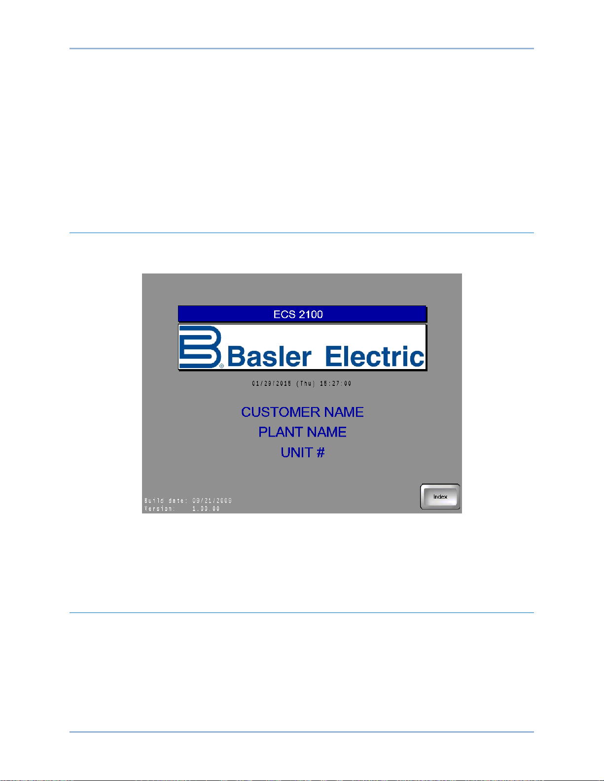
The Initial screen (Figure 1) is displayed upon power-up of the IDP-1200. The initial screen lists the
number of control system channels and the version of the IDP-1200 firmware.
Figure 1. Initial Screen
Index Button
Most screens have an Index button that, when pressed, accesses the General Index screen. The General
Index screen provides quick navigation to any other IDP-1200 screen.
Get Page Button and Screen
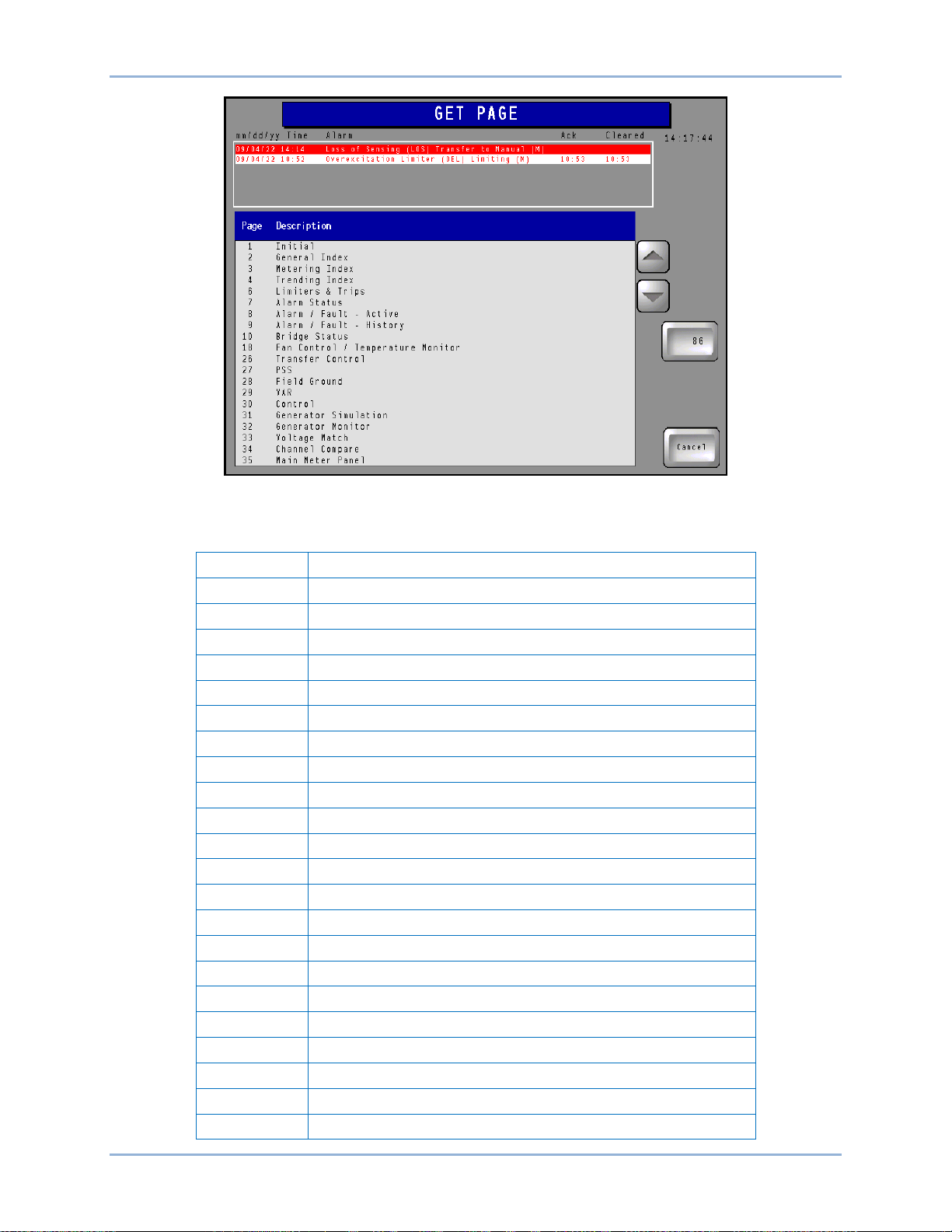
Most screens have a Get Page button that accesses the Get Page screen illustrated in Figure 2. This
screen lists all screens and provides navigation to each screen. To navigate to a screen, the user scrolls
through the screen description list by using the up and down scrolling buttons until the desired screen and
screen number are found. The screen number is entered in a numeric keypad accessed by pressing the
86 button. (This button displays the number of the Get Page screen, which is 86.) Entering the screen
number followed by the Enter (ENT) button takes the user to the requested screen. A complete list of IDP1200 screens is provided in Table 1. Typically, your system/IDP-1200 will not have all of the
equipment/screens listed here.
IDP-1200 IDP-1200 Operation with ECS2100 and ECS/RW
Page 14
6 9437200990 Rev C
Page
Description
1
Initial
2
General Index
3
Metering Index
4
Trending Index
6
Limiters and Trips
7
Alarm Status
8
Alarm/Fault – Active
9
Alarm/Fault – History
10
Bridge 00, 01 Status
11
Bridge 02, 03 Status
12
Bridge 04, 05 Status
13
Bridge 06, 07 Status
14
Bridge 08, 09 Status
15
Bridge 10, 11 Status
16
Bridge 12, 13 Status
17
Bridge 14, 15 Status
18
Fan Control/Temperature Monitor
26
Transfer Control
27
Power System Stabilizer
28
Field Ground
29
Reactive Power
30
Output Control
Figure 2. Get Page Screen
Table 1. IDP-1200 Screens
IDP-1200 Operation with ECS2100 and ECS/RW IDP-1200
Page 15

9437200990 Rev C 7
Page
Description
31
Generator Simulation
32
Generator Monitor
33
Voltage Matching
34
Channel Comparison
35
Main Meter Panel
36
Redundant Meter Panel
37
Supervisory Meter Panel
38
Main Meter Panel – Analog
39
Redundant Meter Panel – Analog
40
Supervisory Meter Panel – Analog
41
Meter Panel – Analog Configuration
42
Generator Meter Panel – Analog
43
Generator Meter Panel – Analog Configuration
44
Meter Trending Graph – Main
45
Meter Trending Data – Main
46
Meter Trending Graph – Redundant
47
Meter Trending Data – Redundant
48
Meter Trending Configuration
49
Bridge 00 Temperature Trending Graph
50
Bridge 00 Temperature Trending Data
51
Bridge 01 Temperature Trending Graph
52
Bridge 01 Temperature Trending Data
53
Bridge 02 Temperature Trending Graph
54
Bridge 02 Temperature Trending Data
55
Bridge 03 Temperature Trending Graph
56
Bridge 03 Temperature Trending Data
57
Bridge 04 Temperature Trending Graph
58
Bridge 04 Temperature Trending Data
59
Bridge 05 Temperature Trending Graph
60
Bridge 05 Temperature Trending Data
61
Bridge 06 Temperature Trending Graph
62
Bridge 06 Temperature Trending Data
63
Bridge 07 Temperature Trending Graph
64
Bridge 07 Temperature Trending Data
65
Bridge 08 Temperature Trending Graph
66
Bridge 08 Temperature Trending Data
67
Bridge 09 Temperature Trending Graph
68
Bridge 09 Temperature Trending Data
69
Bridge 10 Temperature Trending Graph
70
Bridge 10 Temperature Trending Data
IDP-1200 IDP-1200 Operation with ECS2100 and ECS/RW
Page 16

8 9437200990 Rev C
Page
Description
71
Bridge 11 Temperature Trending Graph
72
Bridge 11 Temperature Trending Data
73
Bridge 12 Temperature Trending Graph
74
Bridge 12 Temperature Trending Data
75
Bridge 13 Temperature Trending Graph
76
Bridge 13 Temperature Trending Data
77
Bridge 14 Temperature Trending Graph
78
Bridge 14 Temperature Trending Data
79
Bridge 15 Temperature Trending Graph
80
Bridge 15 Temperature Trending Data
81
Horizontal Capability Curve
82
Vertical Capability Curve
83
System Configuration
84
Cleaning Lock
85
Screen Saver
86
Get Page
87
System Configuration 2
Alarms Banner
Most screens display an alarms banner that lists the six most recent system alarms. Each alarm is
labeled with a description and the date and time of the alarm. The timestamp for acknowledgement and
clearing (if applicable) of alarms is also displayed. Active alarms are displayed as white text on a red
background. Acknowledged alarms are displayed as yellow text on a black background. Cleared alarms
are displayed as red text on a white background.
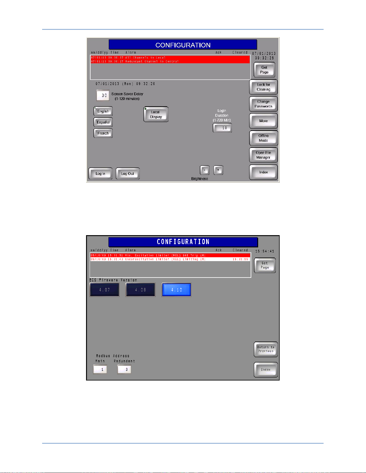
System Configuration Screen
This screen (Figure 3) has provisions for adjusting the screen saver time delay, adjusting the display
brightness, and selecting the display language.
An indicator turns red to indicate the connection of a USB device to the IDP-1200. A button below the
indicator can be pressed to de-energize the IDP-1200 USB port for safe removal of a USB device from
the IDP-1200.
If the IDP-1200 panel requires cleaning, the Lock for Cleaning button can be pressed to enable cleaning
of the screen without inadvertently pressing buttons.
A Log In button accesses an alphanumeric keypad where the appropriate password can be entered to log
in and make IDP-1200 settings changes. The IDP-1200 is delivered with a level 1 password of “1234” and
a level 2 password of “4321”. The proper, level 1 password is required to select the IDP-1200 display
language. The proper level 2 password is required to configure the IDP-1200 as a local or remote display
or to change passwords. Instructions for changing the password are provided in Password Settings.
IDP-1200 Operation with ECS2100 and ECS/RW IDP-1200
Page 17
9437200990 Rev C 9
Figure 3. System Configuration Screen
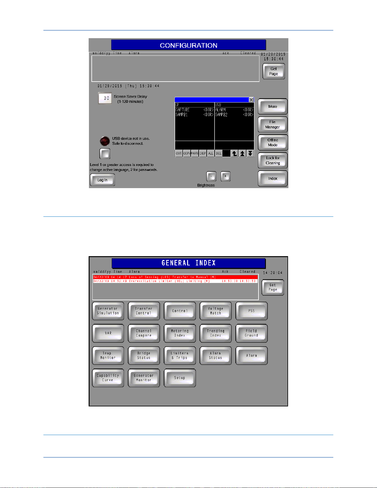
Additional Configuration Screen
Pressing the More button acc ess es a second Config uratio n sc reen, il lustr at ed in Figure 4. This screen
enables selection of the firmware version being used by the control system and the Modbus address of
the main and redundant channels.
Figure 4. Firmware and Modbus Address Configuration Screen
File Manager
The Open File Manager button accesses the file manager which lists the files present on an inserted
compact flash card and connected USB device. Files can be copied or moved from one storage device to
the other or deleted.
IDP-1200 IDP-1200 Operation with ECS2100 and ECS/RW
Page 18
10 9437200990 Rev C
Figure 5. File Manager Screen
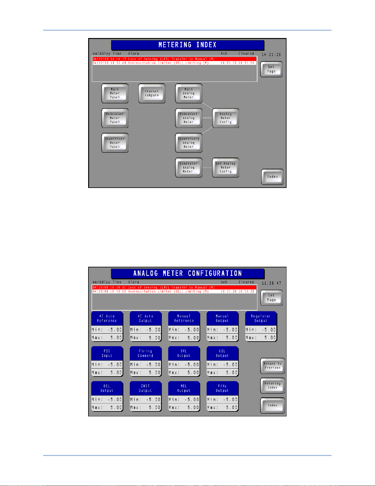
General Index
The General Index screen (Figure 6) is accessed by pressing the Index button, located in the lower right
corner of any other IDP-1200 screen. The General Index screen provides two methods of access to other
screens within the IDP-1200. Buttons on the General Index page provide quick access to 18 frequently
used IDP-1200 screens.
Figure 6. General Index Screen
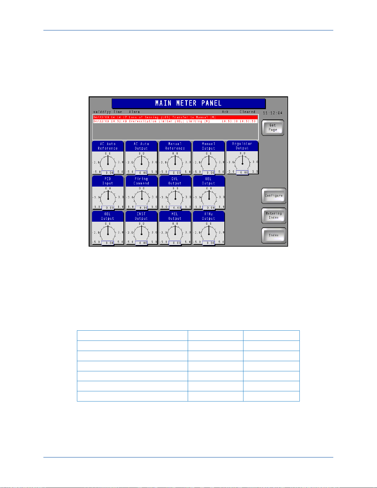
Metering Index
Buttons on the Metering Index screen (Figure 7) are pressed to access the screens used to scale and
display system metering values.
IDP-1200 Operation with ECS2100 and ECS/RW IDP-1200
Page 19
9437200990 Rev C 11
Figure 7. Metering Index Screen
Analog Meter Config Button
Pressing this Metering Index screen button accesses the Analog Meter Configuration screen (Figure 8)
which sets the range of the metering values displayed on the Main, Redundant, and Supervisory Metering
Panels (if so equipped). The minimum and maximum per-unit values for a metered parameter is changed
by pressing the corresponding value. This displays a keypad which is then used to assign the desired
metering limit. A per-unit value of –5.00 to 5.00 may be entered. Pr ess ing the En te r (ENT) button saves
the value.
Figure 8. Analog Meter Configuration Screen
IDP-1200 IDP-1200 Operation with ECS2100 and ECS/RW
Page 20
12 9437200990 Rev C
Parameter
Minimum
Maximum
Field Current
0
10000
Field Voltage
–1500
1500
Generator Current
0
30000
Generator Voltage
0
30000
Generator Megavars
–1500
1500
Generator Megawatts
0
1500
Main Analog Meter, Redundant Analog Meter, and Supervisory Analog Meter Buttons
Pressing one of these Metering Index screen buttons (if so equipped) accesses the corresponding
metering page which displays the parameters illustrated in Figure 9. (Only the Main Meter Panel is shown
here; the Redundant and Supervisory Meter Panels are similar.) The value of each parameter is
graphically shown on an analog scale and also displayed in digital format. The minimum and maximum
values established on the Analog Meter Configuration screen determine the metering ranges shown on
this screen.
Figure 9. Main Meter Panel
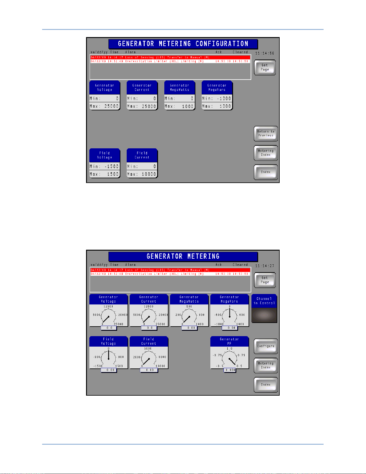
Gen Analog Meter Config Button
Pressing this Metering Index screen button accesses the Generator Metering Configuration screen
(Figure 10) which sets the range of the generator metering values displayed on the Generator Metering
screen. The generator power factor metering range is fixed so no adjustment is provided. The minimum
and maximum value for a metered parameter is changed by pressing the corresponding value. This
displays a keypad which is then used to assign the desired metering limit. Pressing the Enter (ENT)
button saves the value. Minimum and maximum metering parameter ranges are listed in Table 2.
Table 2. Metering Parameter Ranges
IDP-1200 Operation with ECS2100 and ECS/RW IDP-1200
Page 21
9437200990 Rev C 13
Figure 10. Generator Metering Configuration Screen
Generator Analog Meter Button
Pressing this Metering Index screen button accesses the Generator Metering screen which displays the
parameters illustrated in Figure 11. The value of each parameter is graphically shown on an analog scale
and also displayed in digital format. The mini mum and max im um va lues es tab lishe d on the Generator
Metering Configuration screen determine the metering ranges shown on this screen. The Generator
Metering screen also indicates the control system channel that is controlling excitation.
Figure 11. Generator Metering Screen
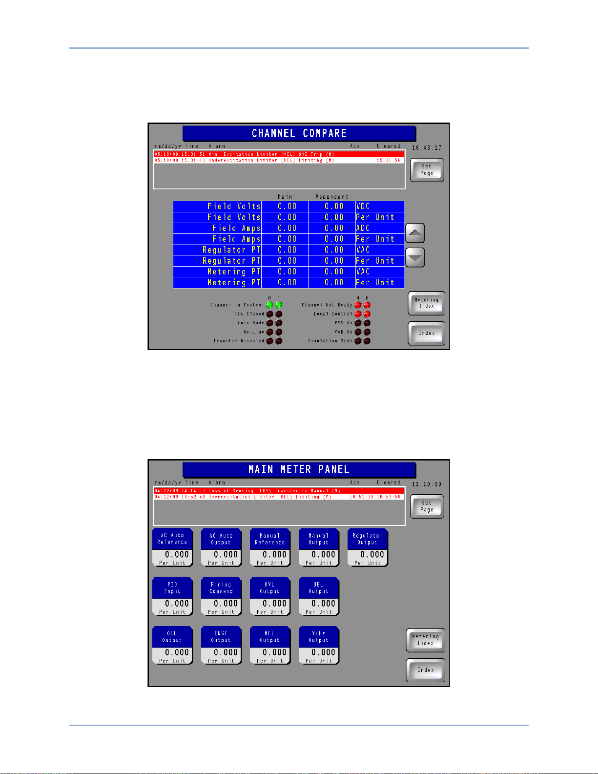
Channel Compare Button
Pressing this Metering Index screen button accesses the Channel Compare screen (Figure 12) which
displays a list of parameters metered by the control system channels. Scroll buttons, located to the right
IDP-1200 IDP-1200 Operation with ECS2100 and ECS/RW
Page 22
14 9437200990 Rev C
of the list, can be used to scroll up and down through the list of parameters. (A particular system may not
be equipped with all of the channels shown here.) Three columns of indicators, located in the lower
portion of the screen, show the status of various operating modes, functions, and devices for the three
channels. The Channel in Control indicators turn green when active; all other indicators turn red when
active.
Figure 12. Channel Compare Screen
Main Meter Panel, Redundant Meter Panel, and Supervisory Meter Panel Buttons
Pressing one of these Metering Index screen buttons (if so equipped) accesses the corresponding meter
panel screen which displays the digital-only version of the parameters illustrated in Figure 9. (Only the
Main Meter Panel (Figure 13) is shown here; the Redundant and Supervisory Meter Panels are similar.)
The minimum and maximum values established on the Analog Meter Configuration page determine the
metering ranges shown on this screen.
Figure 13. Main Meter Panel Screen
IDP-1200 Operation with ECS2100 and ECS/RW IDP-1200
Page 23
9437200990 Rev C 15
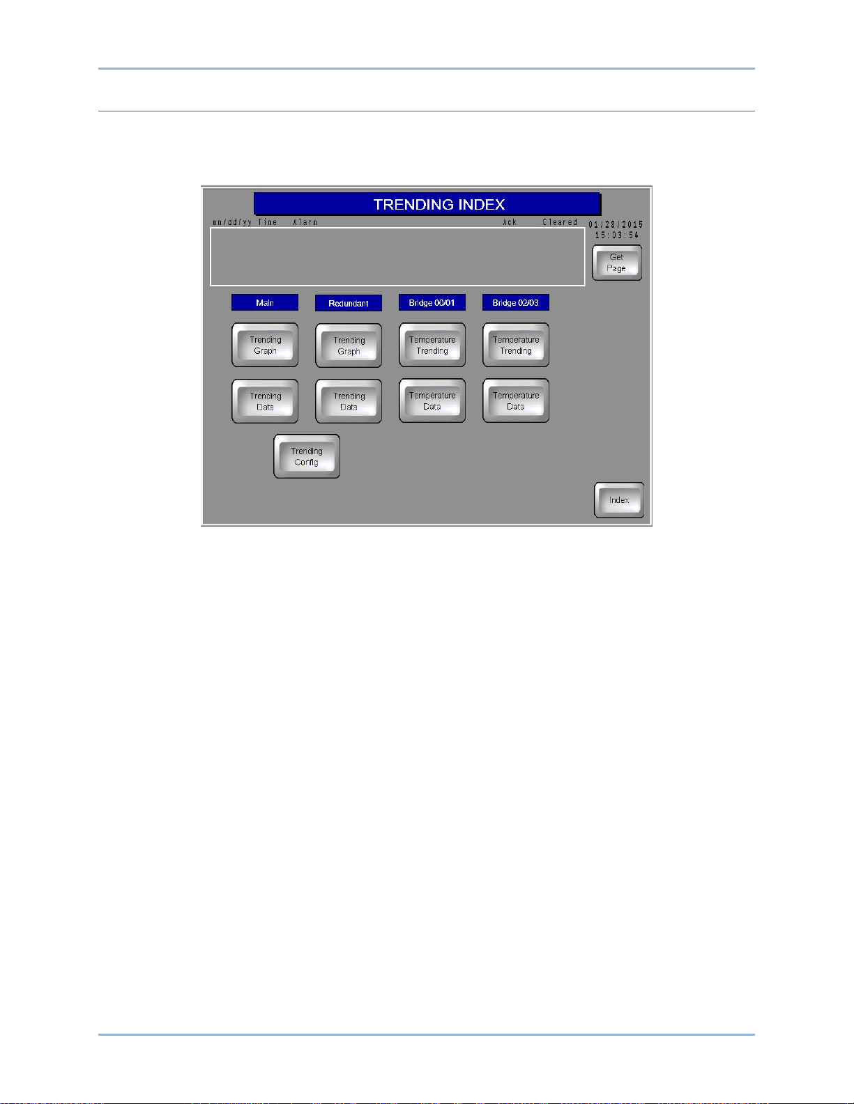
Trending Index
Buttons on the Trending Index screen (Figure 14) provide access to data lists and plots for user-selected
control system parameters and temperature data lists and plots for the excitation system rectifier bridges.
Appropriate buttons are provided based on the number of bridges included in the system.
Figure 14. Trending Index Screen
Trending Config Button
Pressing this Trending Index screen button accesses the Meter Trending Configuration screen shown in
Figure 15. Up to 12 control system channel parameters may be selected as part of a data list (accessed
through the Trending Data buttons) or data graph (accessed through the Trending Graph buttons). A
Duration button can be pressed to access a keypad where the trending length can be selected. Up to
2,400 control channel data points and 100 bridge temperature data points are maintained. A legend
indicates the line colors and patterns used when parameters are graphed.
IDP-1200 IDP-1200 Operation with ECS2100 and ECS/RW
Page 24
16 9437200990 Rev C
Figure 15. Meter Trending Configuration Screen
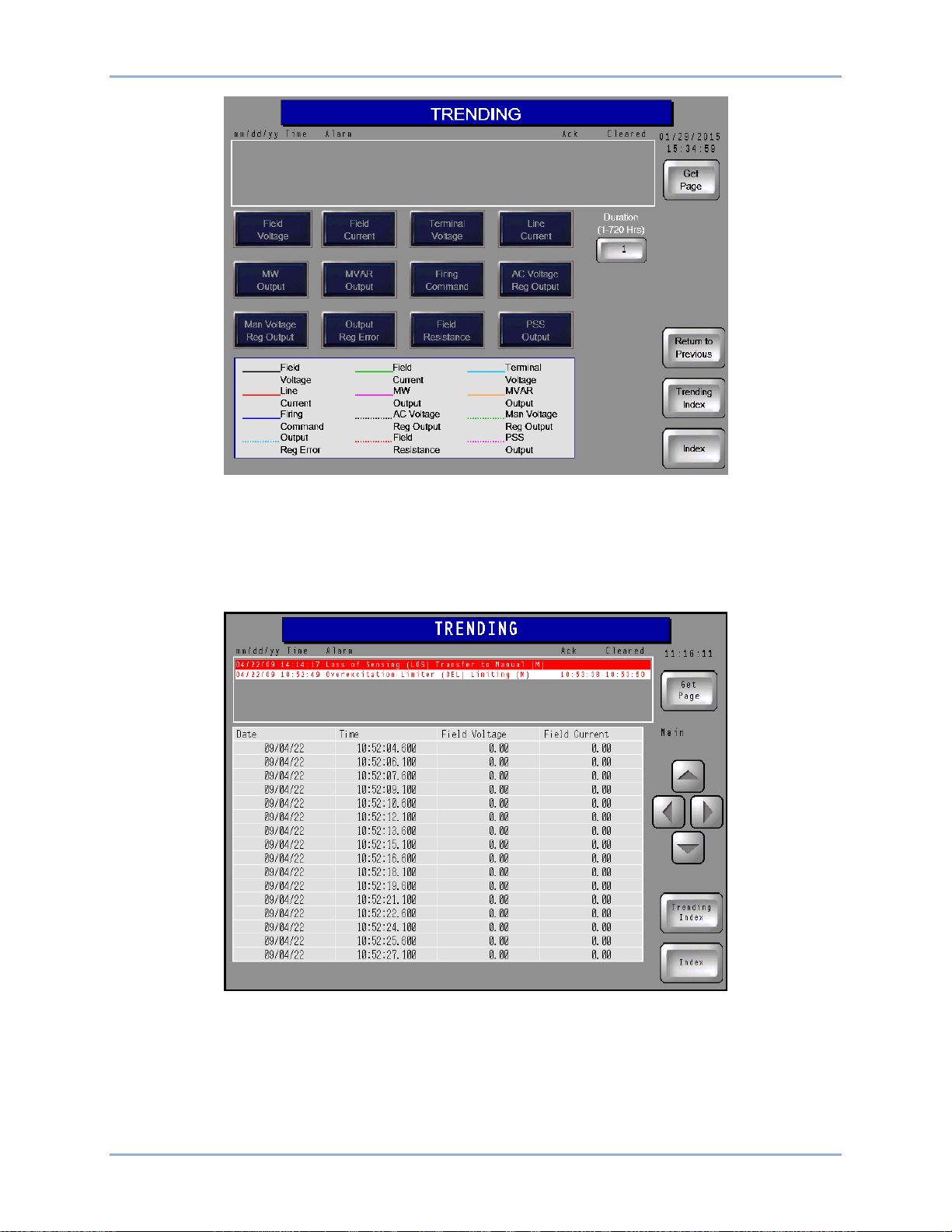
Trending Data Buttons
Pressing these Trending Index screen buttons accesses the corresponding trending page (either the Main
channel trending list or the Redundant channel trending list). The Main channel trending list screen is
shown in Figure 16; the Redundant channel trending list screen is identical in appearance.
Figure 16. Main Channel Trending Data Screen
Parameter data are listed in columns along with dates and timestamps for each row of data. Note that the
date format is yy/mm/dd. The parameters displayed are selected on the Meter Trending Configuration
screen. Scrolling buttons enable the user to move through the record and view the desired data points.
IDP-1200 Operation with ECS2100 and ECS/RW IDP-1200
Page 25
9437200990 Rev C 17
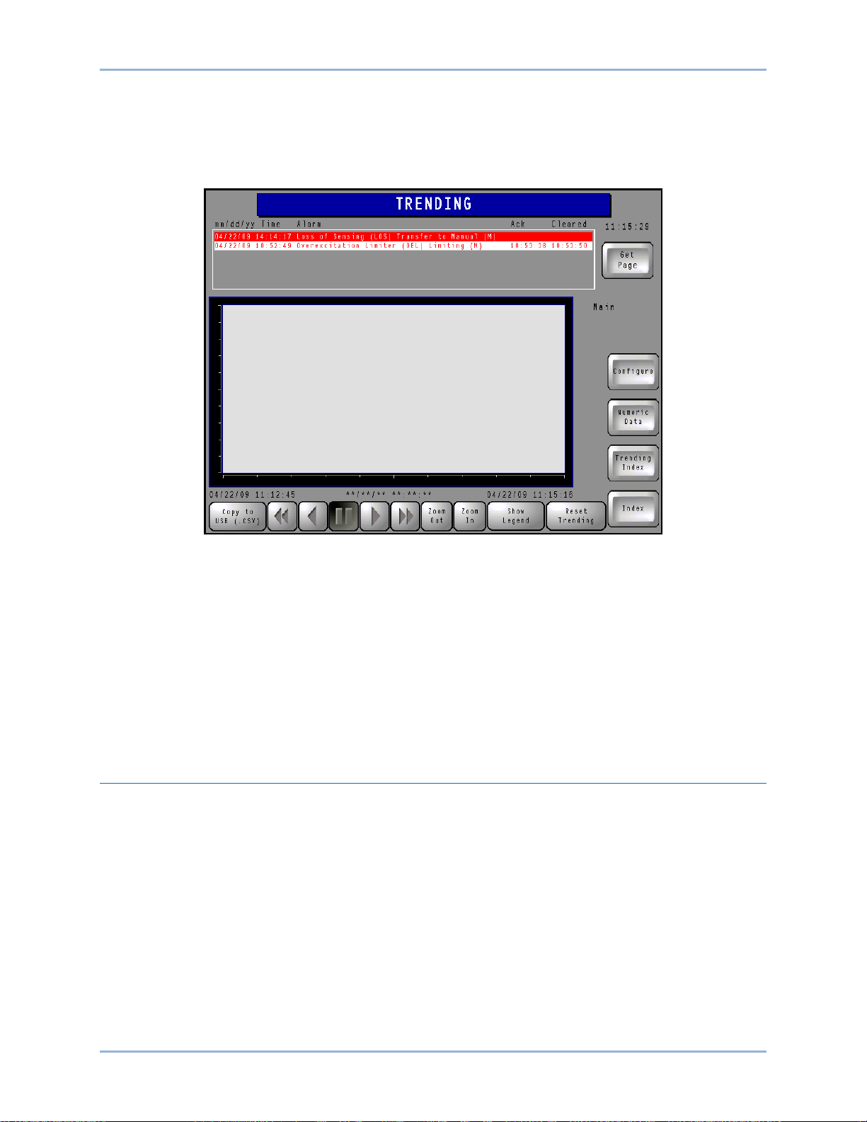
Trending Graph Buttons
Pressing these Trending Index screen buttons accesses the corresponding trending graph page (either
the Main channel trending graph or the Redundant channel trending graph). The Main channel trending
graph screen (Figure 17) is shown here; the Redundant channel trending graph screen is identical in
appearance.
Figure 17. Main Channel Trending Graph Screen
Each trending graph screen has a graph window with buttons that are used to move forward and
backward through the plot, zoom in and out, and reset the plot. Plotted parameters are selected on the
Meter Trending Configuration screen. Pressing the Show Legend button displays a legend indicating the
line colors and patterns used in the trending graph. A Copy to USB button provides the ability to export
the plot data to the IDP-1200’s USB port in a comma-separated-values file format.
Temperature Trending and Temperature Data Buttons
These Trending Index screen buttons are pressed to access a plot or list of temperature data for the
rectifier bridges. Display and control layout of these pages are identical to that of the trending data and
trending graph screens for the control system channels.
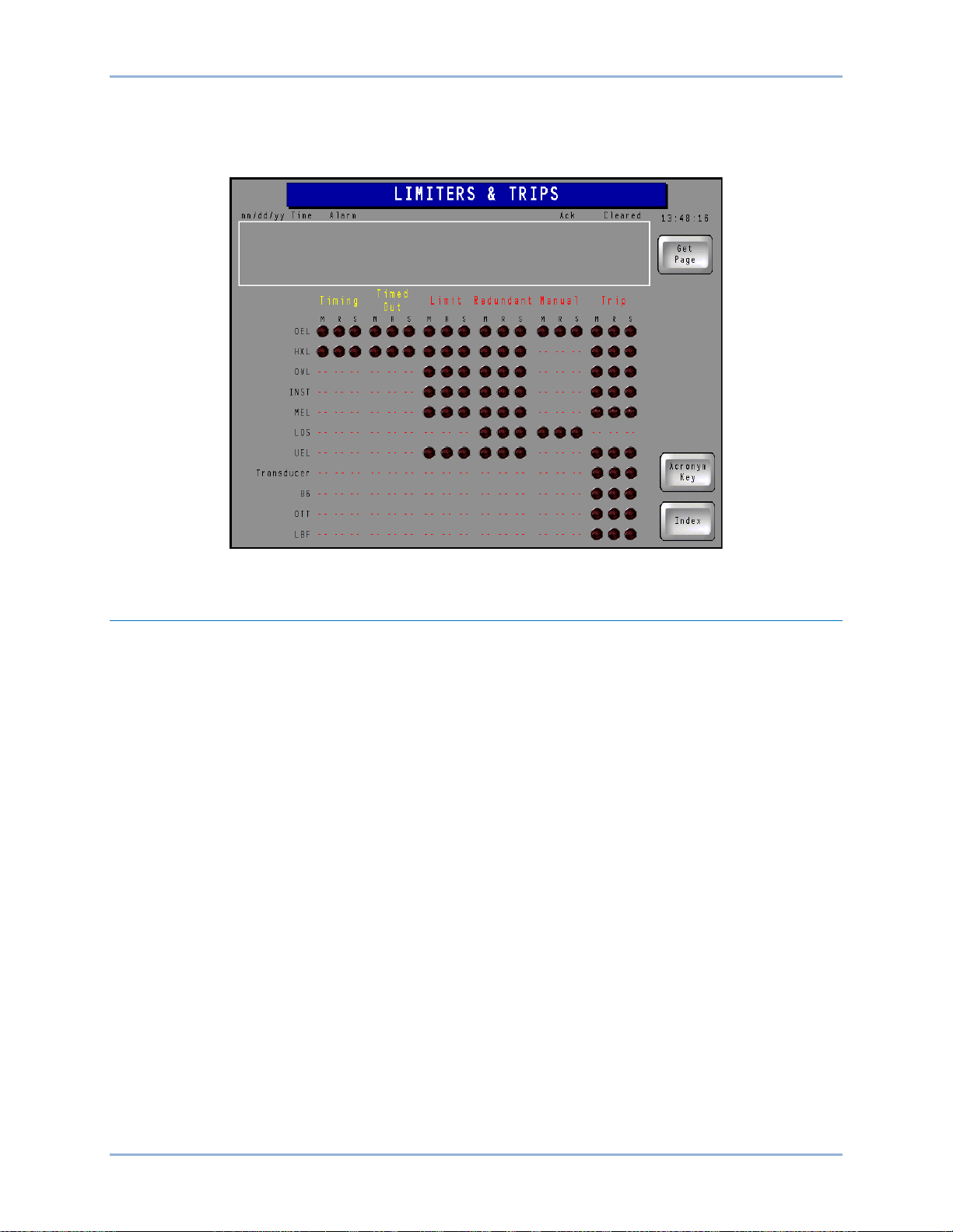
Limiters and Trips
This page (Figure 18) indicates the status of the following limiters and trip actions:
• Overexcitation (OEL)
• Volts per Hertz (HXL)
• Overvoltage (OVL)
• Instantaneous (INST)
• Minimum Excitation (MEL)
• Underexcitation (UEL)
• Loss of Sensing (LOS)
• External Initiated Lockout (86)
• Transformer Overtemperature (OTT)
• Loss of Both Cooling Fans (LBF)
Pressing the Acronym Key button displays a list of acronym definitions for the Limiters & Trips page.
IDP-1200 IDP-1200 Operation with ECS2100 and ECS/RW
Page 26
18 9437200990 Rev C
Limiter/trip status is indicated by up to three columns of red (active) or black (inactive) indicators labeled
M (main channel), R (redundant channel), and S (supervisory channel). The meaning of a red indicator
depends upon the column it is located in. Indication categories (columns) are Timing, Timed Out, Limit,
Redundant, Manual, and Trip.
Figure 18. Limiters and Trips Screen
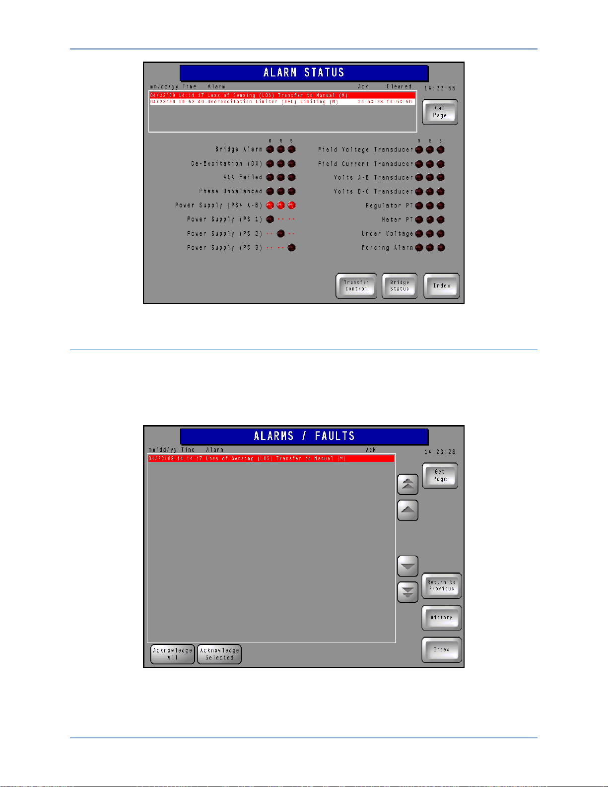
Alarm Status
The Alarm Status screen (Figure 19) lists control system parameters, conditions, and modules along with
their alarm status. Alarm status is displayed by three columns of indicators that are either black (no alarm)
or red (alarm). Depending upon the features of the control system, each parameter has up to three alarm
indicators labeled M (main channel), R (redundant channel), and S (supervisory channel). An active alarm
is annunciated by a red indicator and is listed in the alarms banner along the top of the page. More
information about how alarms are displayed is provided in the description for the Alarms/Faults screen.
Navigation to the Index, Bridge Status, and Transfer Control screen is available through buttons located in
the lower, right portion of the Alarm Status screen.
IDP-1200 Operation with ECS2100 and ECS/RW IDP-1200
Page 27
9437200990 Rev C 19
Figure 19. Alarm Status Screen
Active Alarms/Faults
This screen (Figure 20) lists only alarms that are active. Scrolling buttons along the right side of the list
enable the user to navigate through the list of alarms. Individual alarms can be acknowledged by
selecting the alarm and then pressing the Acknowledge Selected button. All alarms in the list can be
acknowledged simultaneously by pressing the Acknowledge All button. The History button provides
access to the Alarms/Faults History screen.
Figure 20. Active Alarms/Faults Screen
IDP-1200 IDP-1200 Operation with ECS2100 and ECS/RW
Page 28

20 9437200990 Rev C
Alarms/Faults History
This screen (Figure 21) lists all active, acknowledged, and cleared alarms. Active alarms are displayed as
white text on a red background. Alarms that have been acknowledged (but not cleared) are displayed as
yellow text on a black background. Cleared alarms are displayed as red text on a white background.
Scrolling buttons along the right side of the list enable the user to navigate through the list of alarms.
Individual alarms can be acknowledged or cleared by selecting the alarm and then pressing the
Acknowledge Selected or Clear Selected button. All alarms in the list can be simultaneously
acknowledged or cleared by pressing the Acknowledge All or Clear All button. A Copy to USB button
provides the ability to export the plot data to the IDP-1200’s USB port in a comma-separated-values file
format. The History button provides access to the Active Alarms/Faults screen.
Figure 21. Alarms/Faults History Screen
Bridge Status
The Bridge Status screen (Figure 22) displays alarm conditions associated with the excitation system
power converters. This screen indicates the status of up to two power converters; a system with more
than two power converters will have more than one Bridge Status screen.
Alarm indications are provided for open input fuses, open or non-conducting SCRs, open or shorted
RTDs, and cooling failures.
A Reset FCIM Alarms button can be used to reset any alarms associated with the Field Control Interface
Module.
The Return Bridge From Maint button must be pressed when an out-of-service power converter is ready
to be returned to service.
IDP-1200 Operation with ECS2100 and ECS/RW IDP-1200
Page 29

9437200990 Rev C 21
Figure 22. Bridge Status Screen
Fan Control and Temperature Monitor
This screen (Figure 23) displays a table of temperature data for the excitation system rectifier bridges.
Heat sink temperature data is listed for each SCR. The ambient air temperature surrounding the bridge is
also listed.
Buttons at the right side of the page enable the user to override the cooling fan logic and manually select
which fans operate.
Indicators display the operating status of the rectifier bridge cooling fans.
Figure 23. Fan Control and Temperature Monitor Screen
IDP-1200 IDP-1200 Operation with ECS2100 and ECS/RW
Page 30

22 9437200990 Rev C
Transfer Control
This screen (Figure 24) is used to transfer control from one control system channel to another.
When transferring control system channel control, observe the following:
• The IDP-1200 being used must be in control.
• You must know whether the IDP-1200 being used is Local or Remote (as displayed on the
Local/Remote indicator). Note that the IDP-1200 located on the control system equipment
enclosure is considered as the Local IDP-1200. An IDP-1200 at any other location is considered
to be a Remote IDP-1200.
• Level 1 password access is required (through use of the Log In button).
• The redundant channel tracks the output of the main channel and displays the percent difference
(error) between the outputs of the redundant and main channels.
To transfer control system channel control:
1. Ensure that the Enable Transfer indicator shows “Panel Transfer Enabled”. This is achieved by
pressing the Enable Transfer button.
2. Press the Transfer indicator button and select the desired channel.
Figure 24. Transfer Control Screen
Power System Stabilizer
This page (Figure 25) displays power system stabilizer operating status and enables/disables PSS
operation. PSS metering indications for each control system channel are displayed. The PSS output for
the active channel is displayed adjacent to the Channel in Control indicator.
IDP-1200 Operation with ECS2100 and ECS/RW IDP-1200
Page 31

9437200990 Rev C 23
Figure 25. Power System Stabilizer Screen
Field Ground
This is an indications-only screen (Figure 26) that displays the field-to-ground resistance and calculated
field temperature as measured/calculated by each channel. If the level of the field-to-ground resistance is
detected as less than system variable FLDGND_RMIN, an alarm condition exists and is displayed in the
Field Ground indicator(s).
Figure 26. Field Ground Screen
IDP-1200 IDP-1200 Operation with ECS2100 and ECS/RW
Page 32

24 9437200990 Rev C
Var
This screen (Figure 27) is available only on systems equipped with var control.
Control of reactive power is enabled and disabled by the VAR Control button. When this button is
pressed, Enable and Disable buttons will appear and enable the user to turn control of vars on and off.
Var balance is adjusted by pressing the VAR Adjuster button. When the button is pressed, Raise and
Lower buttons will appear and enable the user to raise and lower the level of reactive power.
The 70BC-CS Manual button can be used to raise or lower the balance or manual reference. When the
button is pressed, Raise and Lower buttons will appear and enable the user to raise and lower the voltage
while operating in Manual mode.
Similarly, the 90DV-CS Auto button can be used to raise or lower the voltage while operating in Auto
mode.
Generator and excitation system values are displayed and controls are provided for control of the ac
(41A) breaker.
Figure 27. Var Screen
Output Control
This screen (Figure 28) provides system control, status indication, and metering of generator and
excitation system parameters.
IDP-1200 Operation with ECS2100 and ECS/RW IDP-1200
Page 33

9437200990 Rev C 25
Figure 28. Output Control Screen
Controls
Controls include opening and closing of the ac (41A) breaker, selection of auto- or manual-mode
regulation, and adjustment of the gener at or volt age in Manu al or Auto mod e.
Control of the 41A breaker is provided through the AC Breaker button. When this button is pressed, Trip
and Close buttons will appear and enable the user to open and close the ac breaker.
Selection of auto- or manual-mode regulation is provided through the Mode Select button. When this
button is pressed, Put Reg in Auto and Put Reg in Manual buttons wil l appear and enab le the us er to
select either auto or manual regulation.
The 70BC-CS Manual button can be used to raise or lower the balance or manual reference. When the
button is pressed, Raise and Lower buttons will appear and enable the user to raise and lower the voltage
while operating in Manual mode.
Similarly, the 90DV-CS Auto button can be used to raise or lower the voltage while operating in Auto
mode.
Status Indicators
The System Status indicator displays the readiness of the control system channels.
The Channel in Control indicator displays which of the control system channels is actively controlling the
excitation level.
The Generator Breaker indicator displays whether the generator breaker is open or closed.
The Local/Remote indicator displays the local/remote control status of all control system channels. When
logged in with the Log In button and the proper password, this indicator is converted to a control button
that can be used to select either local or remote control. When pressed, Local Control and Remote
Control buttons appear and enable the user to select the operating mode. During proper operation, the
control mode of all channels should match. That is, all channels should be under local control or all
channels should be under remote control.
Metering
Metering indications are provided for generator voltage, current, watts, vars, and power factor. Metering
indications are also provided for field voltage and current, the SCR firing command percentage, and
IDP-1200 IDP-1200 Operation with ECS2100 and ECS/RW
Page 34

26 9437200990 Rev C
manual/auto setpoint balance. Metering indications with two values display the actual reading in the upper
row of numbers and the per-unit (PU) value in the lower row of numbers.
Generator Simulation
This screen (Figure 29) gives the user the ability to test a group of settings offline. Controls are provided
for enabling and disabling generator simulation (Simulation Enable), raising and lowering the Auto
setpoint (Raise/Lower Volts), raising and lowering the output power (Turbine Control), toggling between
Auto and Manual modes (Mode Select), and tripping and closing the 41A breaker (AC Breaker). Metering
indicators are provided for common generator and excitation system parameters.
Figure 29. Generator Simulation Screen
Generator Monitor
The Generator Monitor screen (Figure 30) graphically illustrates excitation system and generator status.
Excitation system indicators are provided for ac breaker and PSS status and field voltage and current
levels. Generator voltage, current, watts, vars, and power factor are also displayed.
IDP-1200 Operation with ECS2100 and ECS/RW IDP-1200
Page 35

9437200990 Rev C 27
Figure 30. Generator Monitor Screen
Voltage Match
The Voltage Match scr een ( Figure 31) toggles voltage matching on and off (Voltage Match Enable
control) and monitors voltage matching progress through generator and line voltage metering values. A
Voltage Match indicator annunciates when the generator voltage level matches the level of line voltage.
Figure 31. Voltage Match Screen
IDP-1200 IDP-1200 Operation with ECS2100 and ECS/RW
Page 36

28 9437200990 Rev C
Task
Screen
Close ac breaker
Control
Flash the field
N/A, field is flashed automatically
when ac field breaker is closed.
Place regulator in Auto or Manual
mode
Control
Raise or lower voltage
Control
Var
Change the controlling channel
Transfer Control
Change Local/Remote control
Control
View alarms
Any page
Acknowledge alarms
Alarm/Fault – Active
Alarm/Fault – History
Capability Curves
This screen displays the generator minimum excitation limit (MEL) capability curve in per- unit values and
is superimposed on the actual excitation values. The horizontal capability curve screen is shown in Figure
32. A vertical curve is also available. For proper display of plotted values, the version of control system
firmware, resident in the Excitation Control Module (ECM) must be selected on the Capability Curve
Configuration screen. This screen is accessed by pressing the Configure button.
Figure 32. Capability Curve Screen
Task Guide
Table 3 lists common tasks along with the IDP-1200 pages that provide the controls for performing the
tasks.
Table 3. Tasks and Screens Cross-Reference
IDP-1200 Operation with ECS2100 and ECS/RW IDP-1200
Page 37

9437200990 Rev C 29
Mode
PS
Level
Password
1
New
2
New
3
4 5
6 7 8 9
10 11
12 13 14 15
12345
Password Settings
The default, level 2 password is “4321”. Use the following procedure to change the security password. A
USB flash drive is required to change the password.
1. Create a CSV (comma-separated values) file named “Security.csv” that has its content structured
as shown in Table 4. Place the new password where “New” is shown in the table. Passwords are
case sensitive and have a maximum length of eight alphanumeric characters. It is not necessary
to enter a password for levels 3 through 14. The default level 15 password is “12345” and should
not be changed.
2. Insert the USB flash drive into any available USB port on your PC.
®
3. Use normal Windows
4. Copy the CSV file created in Step 1 inside the “Security” directory on the flash drive.
5. Insert the USB flash drive into one of the USB ports on the side of the IDP-1200.
6. Press the Index button on any IDP-1200 page.
7. Press the Setup button on the General Index page.
8. Press the Login button at the bottom of the page.
9. Enter the default security password (4321).
techniques to create a root directory on the flash drive named “Security”.
10. Press the Change Passw ord s button located on the right side of the page.
11. If successful, the unit will display “Password change successful” to the left of the Change
Passwords button.
12. If the unit displays “Password file not found”, verify that the CSV file is valid, named correctly, and
located in the proper directory on the flash drive.
Table 4. Security.csv File Structure
Updating IDP-1200 Configur a t ion Files from Basler Electric
Use the following procedure to upload an IDP-1200 settings/software file provided by Basler Electric.
1. Copy the configuration file (*.cml) onto a USB flash drive in the root directory.
IDP-1200 IDP-1200 Operation with ECS2100 and ECS/RW
Page 38

30 9437200990 Rev C
2. Open the IDP Loader folder and copy the /prj001 folder and boot.cfg file onto the USB flash drive
in the root directory.
3. Insert the drive into one of the USB ports on the side of the IDP-1200
4. Press the Index button on any IDP-1200 page to access the General Index page.
5. Tap in the upper, left corner of the page and, within one second, tap in the lower right corner of
the page. If done correctly, a menu should appear at the bottom of the page.
6. Press the CF/USB button at the bottom of the page.
7. Press the USB_Starting button at the bottom of the page.
8. Tap on the language box in the center of the page and select the desired language.
9. Press the Download (USB=>Display) button located to the right of the page center.
10. Select the configuration file (*.cml) file from the file list.
11. Tap on the password box in the center of the page and enter the appropriate password. (The
default password is “5678”. On the popup control, use the Down arrow to toggle between letters
and numbers.)
12. Press the Start button located in the center of the page.
13. Press the Yes button when asked to download the data. Downloading settings from a USB flash
drive to the IDP-1200 takes approximately three minutes.
14. After completion of the download, press the Back button located at the bottom of the page.
15. Press the Back button again.
16. Press the Exit button at the bottom of the page.
17. Press the Yes button when prompted to restart the system.
Updating IDP-1200 Configur a t ion Files from Documentation CD
Configuration files are included on the documentation CD that accompanies the manual for this excitation
system. If replacement of a display panel becomes necessary, the provided files enable you to program
the new IDP-1200 to ensure proper functionality with your system or application.
Use the following procedure to upload an IDP-1200 configuration file provided by Basler Electric.
1. Open the Configuration Files folder on the documentation CD and copy the configuration file
(*.cml) onto a USB flash drive in the root directory.
2. Open the IDP Loader folder and copy the /prj001 folder and boot.cfg file onto the USB flash drive
in the root directory.
3. Insert the drive into one of the USB ports on the side of the IDP-1200.
4. Press the Index button on any IDP-1200 page to access the General Index page.
5. Tap in the upper, left corner of the page and, within one second, tap in the lower right corner of
the page. If done correctly, a menu should appear at the bottom of the page.
6. Press the CF/USB button at the bottom of the page.
7. Press the USB_Starting button at the bottom of the page.
8. Tap on the language box in the center of the page and select the desired language.
9. Press the Download (USB=>Display) button located to the right of the page center.
10. Select the configuration file (*.cml) file from the file list.
IDP-1200 Operation with ECS2100 and ECS/RW IDP-1200
Page 39

9437200990 Rev C 31
11. Tap on the password box in the center of the page and enter the appropriate password. (The
default password is “5678”. On the popup control, use the Down arrow to toggle between letters
and numbers.)
12. Press the Start button located in the center of the page.
13. Press the Yes button when asked to download the data. Downloading settings from a USB flash
drive to the IDP-1200 takes approximately three minutes.
14. After completion of the download, press the Back button located at the bottom of the page.
15. Press the Back button again.
16. Press the Exit button at the bottom of the page.
17. Press the Yes button when prompted to restart the system.
IDP-1200 IDP-1200 Operation with ECS2100 and ECS/RW
Page 40

32 9437200990 Rev C
IDP-1200 Operation with ECS2100 and ECS/RW IDP-1200
Page 41

9437200990 Rev C 33
IDP-1200 Operation with DECS-2100 and DECS/RW
Control system and generator system parameters are viewed and controlled through interactive screens
displayed by the IDP-1200. Screens are organized by function. Navigation between screens and control
of functions are achieved by pressing buttons located on the IDP-1200 screens.
This chapter illustrates and describes IDP-1200 screen navigation and usage. The available IDP-1200
screens and their appearance will vary according to the number of control channels and rectifier bridges
utilized in a particular control system.
Initial Screen
The Initial screen (Figure 33) is displayed upon power-up of the IDP-1200. The initial screen lists the
version of the IDP-1200 firmware.
Figure 33. Initial Screen
Index Button
Most screens have an Index button that, when pressed, accesses the General Index screen. The General
Index screen provides quick navigation to any other IDP-1200 screen.
Get Page Button and Screen
Most screens have a Get Page button that accesses the Get Page screen illustrated in Figure 34. This
screen lists all screens and provides navigation to each screen. To navigate to a screen, the user scrolls
through the screen description list by using the up and down scrolling buttons until the desired screen and
screen number are found. The screen number is entered in a numeric keypad accessed by pressing the
86 button. (This button displays the number of the Get Page screen, which is 86.) Entering the screen
number followed by the Enter (ENT) button takes the user to the requested screen. A complete list of IDP1200 screens is provided in Table 5. Typically, your system/IDP-1200 will not have all of the
equipment/screens listed here.
IDP-1200 IDP-1200 Operation with DECS-2100 and DECS/RW
Page 42

34 9437200990 Rev C
Page
Description
1
Initial
2
General Index
3
Metering Index
4
Trending Index
6
Limiters and Trips
7
Alarm Status
8
Alarm/Fault – Active
9
Alarm/Fault – History
10
Bridge 00, 01 Status
11
Bridge 02, 03 Status
12
Bridge 04, 05 Status
13
Bridge 06, 07 Status
14
Bridge 08, 09 Status
15
Bridge 10, 11 Status
16
Bridge 12, 13 Status
17
Bridge 14, 15 Status
18
Fan Control/Temperature Monitor
19
Fan Control/Temperature Monitor
22
Voltage Match
23
Power Factor
24
Synchronizer
25
Synchronizer Display
Figure 34. Get Page Screen
Table 5. IDP-1200 Screens
IDP-1200 Operation with DECS-2100 and DECS/RW IDP-1200
Page 43

9437200990 Rev C 35
Page
Description
26
Transfer Control
27
Power System Stabilizer
28
Field Ground
29
Reactive Power
30
Output Control
31
Generator Simulation
32
Generator Monitor
34
Channel Comparison
35
Main Meter Panel
36
Redundant Meter Panel
38
Main Meter Panel – Analog
39
Redundant Meter Panel – Analog
41
Meter Panel – Analog Configuration
42
Generator Meter Panel – Analog
43
Generator Meter Panel – Analog Configuration
44
Meter Trending Graph – Main
45
Meter Trending Data – Main
46
Meter Trending Graph – Redundant
47
Meter Trending Data – Redundant
48
Meter Trending Configuration
49
Bridge 00 Temperature Trending Graph
50
Bridge 00 Temperature Trending Data
51
Bridge 01 Temperature Trending Graph
52
Bridge 01 Temperature Trending Data
53
Bridge 02 Temperature Trending Graph
54
Bridge 02 Temperature Trending Data
55
Bridge 03 Temperature Trending Graph
56
Bridge 03 Temperature Trending Data
57
Bridge 04 Temperature Trending Graph
58
Bridge 04 Temperature Trending Data
59
Bridge 05 Temperature Trending Graph
60
Bridge 05 Temperature Trending Data
61
Bridge 06 Temperature Trending Graph
62
Bridge 06 Temperature Trending Data
63
Bridge 07 Temperature Trending Graph
64
Bridge 07 Temperature Trending Data
65
Bridge 08 Temperature Trending Graph
66
Bridge 08 Temperature Trending Data
67
Bridge 09 Temperature Trending Graph
68
Bridge 09 Temperature Trending Data
IDP-1200 IDP-1200 Operation with DECS-2100 and DECS/RW
Page 44

36 9437200990 Rev C
Page
Description
69
Bridge 10 Temperature Trending Graph
70
Bridge 10 Temperature Trending Data
71
Bridge 11 Temperature Trending Graph
72
Bridge 11 Temperature Trending Data
73
Bridge 12 Temperature Trending Graph
74
Bridge 12 Temperature Trending Data
75
Bridge 13 Temperature Trending Graph
76
Bridge 13 Temperature Trending Data
77
Bridge 14 Temperature Trending Graph
78
Bridge 14 Temperature Trending Data
79
Bridge 15 Temperature Trending Graph
80
Bridge 15 Temperature Trending Data
81
Horizontal Capability Curve
82
Vertical Capability Curve
83
System Configuration
84
Cleaning Lock
85
Screen Saver
86
Get Page
88
File Manager
Alarms Banner
Most screens display an alarms banner that lists the six most recent system alarms. Each alarm is
labeled with a description and the date and time of the alarm. The timestamp for acknowledgement and
clearing (if applicable) of alarms is also displayed. Active alarms are displayed as white text on a red
background. Acknowledged alarms are displayed as yellow text on a black background. Cleared alarms
are displayed as red text on a white background.
System Configuration Screen
This screen (Figure 35) has provisions for adjusting the screen saver time delay, adjusting the display
brightness, and selecting the display language.
If the IDP-1200 panel requires cleaning, the Lock for Cleaning button can be pressed to enable cleaning
of the screen without inadvertently pressing buttons.
A Log In button accesses an alphanumeric keypad where the appropriate password can be entered to log
in and make IDP-1200 settings changes. The IDP-1200 is delivered with a level 1 password of “1234” and
a level 2 password of “4321”. The proper, level 1 password is required to select the IDP-1200 display
language. The proper level 2 password is required to configure the IDP-1200 as a local or remote display
or to change passwords. Instructions for changing the password are provided in Password Settings.
IDP-1200 Operation with DECS-2100 and DECS/RW IDP-1200
Page 45

9437200990 Rev C 37
Figure 35. System Configuration Screen
File Manager
The Open File Manager button accesses the file manager which lists the files present on an inserted
compact flash card and connected USB device. Files can be copied or moved from one storage device to
the other or deleted. This button also accesses the file manager where you can download event records.
See Figure 36.
Figure 36. File Manager Screen
An indicator turns red to indicate the connection of a USB device to the IDP-1200. A button below the
indicator can be pressed to de-energize the IDP-1200 USB port for safe removal of a USB device from
the IDP-1200.
IDP-1200 IDP-1200 Operation with DECS-2100 and DECS/RW
Page 46

38 9437200990 Rev C
Downloading Event Records
The following procedure is used to download event records.
Step 1. Insert a USB drive into the USB 2 port on the front of the ECM-2 (Main).
Step 2. Using the IDP-1200, navigate to the General Index screen.
Step 3. Press Setup to enter the Configuration screen.
Step 4. On the Configuration screen, select Open File Manager.
Step 5. Verify that the M (Main) indicator next to “USB Device Ready” is illuminate d .
Step 6. Press the “Download Data From Controller” button under M (Main).
Step 7. Wait until the M (Main) indicator next to “USB Download Complete” illuminates.
Step 8. Press the “Push to Safely Remove USB Device” button under M (Main).
Step 9. Wait until the M (Main) indicator next to “USB Device Not In Use.” illuminates.
Step 10. Remove the USB drive.
General Index
The General Index screen (Figure 37) is accessed by pressing the Index button, located in the lower right
corner of any other IDP-1200 screen. The General Index screen provides two methods of access to other
screens within the IDP-1200. Buttons on the General Index page provide quick access to 20 frequently
used IDP-1200 screens.
Figure 37. General Index Screen
Metering Index
Buttons on the Metering Index screen (Figure 38) are pressed to access the screens used to scale and
display system metering values.
IDP-1200 Operation with DECS-2100 and DECS/RW IDP-1200
Page 47

9437200990 Rev C 39
Figure 38. Metering Index Screen
Analog Meter Config Button
Pressing this Metering Index screen button accesses the Analog Meter Configuration screen (Figure 39)
which sets the range of the metering values displayed on the Main, Redundant, and Supervisory Metering
Panels (if so equipped). The minimum and maximum per-unit values for a metered parameter is changed
by pressing the corresponding value. This displays a keypad which is then used to assign the desired
metering limit. A per-unit value of –5.00 to 5.00 may be entered. Pr ess ing the En ter (ENT) button saves
the value.
Figure 39. Analog Meter Configuration Screen
IDP-1200 IDP-1200 Operation with DECS-2100 and DECS/RW
Page 48

40 9437200990 Rev C
Parameter
Minimum
Maximum
Field Current
0
10000
Field Voltage
–1500
1500
Generator Current
0
30000
Generator Voltage
0
30000
Generator Megavars
–1500
1500
Generator Megawatts
0
1500
Main Analog Meter, Redundant Analog Meter, and Supervisory Analog Meter Buttons
Pressing one of these Metering Index screen buttons (if so equipped) accesses the corresponding
metering page which displays the parameters illustrated in Figure 40. (Only the Main Meter Panel is
shown here; the Redundant and Supervisory Meter Panels are similar.) The value of each parameter is
graphically shown on an analog scale and also displayed in digital format. The minimum and maximum
values established on the Analog Meter Configuration screen determine the metering ranges shown on
this screen.
Figure 40. Main Meter Panel
Gen Analog Meter Config Button
Pressing this Metering Index screen button accesses the Generator Metering Configuration screen
(Figure 41) which sets the range of the generator metering values displayed on the Generator Metering
screen. The generator power factor metering range is fixed so no adjustment is provided. The minimum
and maximum value for a metered parameter is changed by pressing the corresponding value. This
displays a keypad which is then used to assign the desired metering limit. Pressing the Enter (ENT)
button saves the value. Minimum and maximum metering parameter ranges are listed in Table 6.
Table 6. Metering Parameter Rang es
IDP-1200 Operation with DECS-2100 and DECS/RW IDP-1200
Page 49

9437200990 Rev C 41
Figure 41. Generator Metering Configuration Screen
Generator Analog Meter Button
Pressing this Metering Index screen button accesses the Generator Metering screen which displays the
parameters illustrated in Figure 42. The value of each parameter is graphically shown on an analog scale
and also displayed in digital format. The mini mum and max im um va lues es tab lishe d on the Generator
Metering Configuration screen determine the metering ranges shown on this screen. The Generator
Metering screen also indicates the control system channel that is controlling excitation.
Figure 42. Generator Metering Screen
Channel Compare Button
Pressing this Metering Index screen button accesses the Channel Compare screen (Figure 43) which
displays a list of parameters metered by the control system channels. Scroll buttons, located to the right
IDP-1200 IDP-1200 Operation with DECS-2100 and DECS/RW
Page 50

42 9437200990 Rev C
of the list, can be used to scroll up and down through the list of parameters. (A particular system may not
be equipped with all of the channels shown here.) Three columns of indicators, located in the lower
portion of the screen, show the status of various operating modes, functions, and devices for the three
channels. The Channel in Control indicators turn green when active; all other indicators turn red when
active.
Figure 43. Channel Compare Screen
Main Meter Panel, Redundant Meter Panel, and Supervisory Meter Panel Buttons
Pressing one of these Metering Index screen buttons (if so equipped) accesses the corresponding meter
panel screen which displays the digital-only version of the parameters illustrated in Figure 40. (Only the
Main Meter Panel (Figure 44) is shown here; the Redundant and Supervisory Meter Panels are similar.)
The minimum and maximum values established on the Analog Meter Configuration page determine the
metering ranges shown on this screen.
IDP-1200 Operation with DECS-2100 and DECS/RW IDP-1200
Page 51

9437200990 Rev C 43
Figure 44. Main Meter Panel Screen
Trending Index
Buttons on the Trending Index screen (Figure 45) provide access to data lists and plots for user-selected
control system parameters and temperature data lists and plots for the excitation system rectifier bridges.
Appropriate buttons are provided based on the number of bridges included in the system.
Figure 45. Trending Index Screen
Trending Config Button
Pressing this Trending Index screen button accesses the Meter Trending Configuration screen shown in
Figure 46. Up to 12 control system channel parameters may be selected as part of a data list (accessed
through the Trending Data buttons) or data graph (accessed through the Trending Graph buttons). A
IDP-1200 IDP-1200 Operation with DECS-2100 and DECS/RW
Page 52

44 9437200990 Rev C
Duration button can be pressed to access a keypad where the trending length can be selected. Up to
2,400 control channel data points and 100 bridge temperature data points are maintained. A legend
indicates the line colors and patterns used when parameters are graphed.
Figure 46. Meter Trending Configuration Screen
Trending Data Buttons
Pressing these Trending Index screen buttons accesses the corresponding trending page (either the Main
channel trending list or the Redundant channel trending list). The Main channel trending list screen is
shown in Figure 47; the Redundant channel trending list screen is identical in appearance.
Figure 47. Main Channel Trending Data Screen
Parameter data are listed in columns along with dates and timestamps for each row of data. Note that the
date format is yy/mm/dd. The parameters displayed are selected on the Meter Trending Configuration
screen. Scrolling buttons enable the user to move through the record and view the desired data points.
IDP-1200 Operation with DECS-2100 and DECS/RW IDP-1200
Page 53

9437200990 Rev C 45
Trending Graph Buttons
Pressing these Trending Index screen buttons accesses the corresponding trending graph page (either
the Main channel trending graph or the Redundant channel trending graph). The Main channel trending
graph screen (Figure 48) is shown here; the Redundant channel trending graph screen is identical in
appearance.
Figure 48. Main Channel Trending Graph Screen
Each trending graph screen has a graph window with buttons that are used to move forward and
backward through the plot, zoom in and out, and reset the plot. Plotted parameters are selected on the
Meter Trending Configuration screen. Pressing the Show Legend button displays a legend indicating the
line colors and patterns used in the trending graph. A Copy to USB button provides the ability to export
the plot data to the IDP-1200’s USB port in a comma-separated-values file format.
Temperature Trending and Temperature Data Buttons
These Trending Index screen buttons are pressed to access a plot or list of temperature data for the
rectifier bridges. Display and control layout of these pages are identical to that of the trending data and
trending graph screens for the control system channels.
Limiters and Trips
This page (Figure 49) indicates the status of the following limiters and trip actions:
• Overexcitation (OEL)
• Volts per Hertz (HXL)
• Overvoltage (OVL)
• Instantaneous (INST)
• Minimum Excitation (MEL)
• Underexcitation (UEL)
• Loss of Sensing (LOS)
• External Initiated Lockout (86)
• Transformer Overtemperature (OTT)
• Loss of Both Cooling Fans (LBF)
Pressing the Acronym Key button displays a list of acronym definitions for the Limiters & Trips page.
IDP-1200 IDP-1200 Operation with DECS-2100 and DECS/RW
Page 54

46 9437200990 Rev C
Limiter/trip status is indicated by up to three columns of red (active) or black (inactive) indicators labeled
M (main channel), R (redundant channel), and S (supervisory channel). The meaning of a red indicator
depends upon the column it is located in. Indication categories (columns) are Timing, Timed Out, Limit,
Redundant, Manual, and Trip.
Figure 49. Limiters and Trips Screen
Alarm Status
The Alarm Status screen (Figure 50) lists control system parameters, conditions, and modules along with
their alarm status. Alarm status is displayed by three columns of indicators that are either black (no alarm)
or red (alarm). Depending upon the features of the control system, each parameter has up to three alarm
indicators labeled M (main channel), R (redundant channel), and S (supervisory channel). An active alarm
is annunciated by a red indicator and is listed in the alarms banner along the top of the page. More
information about how alarms are displayed is provided in the description for the Alarms/Faults screen.
Navigation to the Index, Bridge Status, and Transfer Control screen is available through buttons located in
the lower, right portion of the Alarm Status screen.
IDP-1200 Operation with DECS-2100 and DECS/RW IDP-1200
Page 55

9437200990 Rev C 47
Figure 50. Alarm Status Screen
Active Alarms/Faults
This screen (Figure 51) lists only alarms that are active. Scrolling buttons along the right side of the list
enable the user to navigate through the list of alarms. Individual alarms can be acknowledged by
selecting the alarm and then pressing the Acknowledge Selected button. All alarms in the list can be
acknowledged simultaneously by pressing the Acknowledge All button. The History button provides
access to the Alarms/Faults History screen.
Figure 51. Active Alarms/Faults Screen
IDP-1200 IDP-1200 Operation with DECS-2100 and DECS/RW
Page 56

48 9437200990 Rev C
Alarms/Faults History
This screen (Figure 52) lists all active, acknowledged, and cleared alarms. Active alarms are displayed as
white text on a red background. Alarms that have been acknowledged (but not cleared) are displayed as
yellow text on a black background. Cleared alarms are displayed as red text on a white background.
Scrolling buttons along the right side of the list enable the user to navigate through the list of alarms.
Individual alarms can be acknowledged or cleared by selecting the alarm and then pressing the
Acknowledge Selected or Clear Selected button. All alarms in the list can be simultaneously
acknowledged or cleared by pressing the Acknowledge All or Clear All button. A Copy to USB button
provides the ability to export the plot data to the IDP-1200’s USB port in a comma-separated-values file
format. The History button provides access to the Active Alarms/Faults screen.
Figure 52. Alarms/Faults History Screen
Bridge Status
The Bridge Status screen (Figure 53) displays alarm conditions associated with the excitation system
power converters. This screen indicates the status of up to two power converters; a system with more
than two power converters will have more than one Bridge Status screen.
Alarm indications are provided for open input fuses, open or non-conducting SCRs, open or shorted
RTDs, and cooling failures.
A Reset Alarms button can be used to reset any alarms associated with the Bridge Control Module.
The Return Bridge From Maint button must be pressed when an out-of-service power converter is ready
to be returned to service.
IDP-1200 Operation with DECS-2100 and DECS/RW IDP-1200
Page 57

9437200990 Rev C 49
Figure 53. Bridge Status Screen
Fan Control and Temperature Monitor
This screen (Figure 54) displays a table of temperature data for the excitation system rectifier bridges.
Heat sink temperature data is listed for each SCR. The ambient air temperature surrounding the bridge is
also listed.
Buttons at the right side of the page enable the user to override the cooling fan logic and manually select
which fans operate.
Indicators display the operating status of the rectifier bridge cooling fans.
Figure 54. Fan Control and Temperature Monitor Screen
IDP-1200 IDP-1200 Operation with DECS-2100 and DECS/RW
Page 58

50 9437200990 Rev C
Transfer Control
This screen (Figure 55) is used to transfer control from one control system channel to another.
When transferring control system channel control, observe the following:
• The IDP-1200 being used must be in control.
• You must know whether the IDP-1200 being used is Local or Remote (as displayed on the
Local/Remote indicator). Note that the IDP-1200 located on the control system equipment
enclosure is considered as the Local IDP-1200. An IDP-1200 at any other location is considered
to be a Remote IDP-1200.
• Level 1 password access is required (through use of the Log In button).
• The redundant channel tracks the output of the main channel and displays the percent difference
(error) between the outputs of the redundant and ma in c hanne ls.
To transfer control system channel control:
1. Ensure that the Enable Transfer indicator shows “Panel Transfer Enabled”. This is achieved by
pressing the Enable Transfer button.
2. Press the Transfer indicator button and select the desired channel.
Figure 55. Transfer Control Screen
Power System Stabilizer
This page (Figure 56) displays power system stabilizer operating status and enables/disables PSS
operation. PSS metering indications for each control system channel are displayed. The PSS output for
the active channel is displayed adjacent to the Channel in Control indicator.
IDP-1200 Operation with DECS-2100 and DECS/RW IDP-1200
Page 59

9437200990 Rev C 51
Figure 56. Power System Stabilizer Screen
Field Ground
This is an indications-only screen (Figure 57) that displays the field-to-ground resistance and calculated
field temperature as measured/calculated by each channel. If the level of the field-to-ground resistance is
detected as less than system variable FLDGND_RMIN, an alarm condition exists and is displayed in the
Field Ground indicator(s).
Figure 57. Field Ground Screen
IDP-1200 IDP-1200 Operation with DECS-2100 and DECS/RW
Page 60

52 9437200990 Rev C
Var
This screen (Figure 58) is available only on systems equipped with var control.
Control of reactive power is enabled and disabled by the VAR Control button. When this button is
pressed, Enable and Disable buttons will appear and enable the user to turn control of vars on and off.
Var balance is adjusted by pressing the VAR Adjuster button. When the button is pressed, Raise and
Lower buttons will appear and enable the user to raise and lower the level of reactive power.
The 70BC-CS Manual button can be used to raise or lower the balance or manual reference. When the
button is pressed, Raise and Lower buttons will appear and enable the user to raise and lower the voltage
while operating in Manual mode.
Similarly, the 90DV-CS Auto button can be used to raise or lower the voltage while operating in Auto
mode.
Generator and excitation system values are displayed and controls are provided for control of the ac
(41A) breaker.
Figure 58. Var Screen
Power Factor
This Power Factor screen is shown in Figure 59. This screen is only available on systems with PF control.
Control of power factor is enabled and disabled by the PF Control button. When this button is pressed,
Enable and Disable buttons will appear and enable the user to turn control of power factor on and off.
Power factor balance is adjusted by press ing the PF A djuster butt on. Wh en the button is pressed, Raise
and Lower buttons will appear and enable the user to raise and lower the power factor.
The 70BC-CS Manual button can be used to raise or lower the balance or manual reference. When the
button is pressed, Raise and Lower buttons will appear and enable the user to raise and lower the voltage
while operating in Manual mode.
Similarly, the 90DV-CS Auto button can be used to raise or lower the voltage while operating in Auto
mode.
Generator and excitation system values are displayed and controls are provided for control of the ac
(41A) breaker.
IDP-1200 Operation with DECS-2100 and DECS/RW IDP-1200
Page 61

9437200990 Rev C 53
Figure 59. Power Factor Screen
Output Control
This screen (Figure 60) provides system control, status indication, and metering of generator and
excitation system parameters.
Figure 60. Output Control Screen
Controls
Controls include opening and closing of the ac (41A) breaker, selection of auto- or manual-mode
regulation, and adjustment of the gener at or volt age in Manu al or Auto mod e.
Control of the 41A breaker is provided through the AC Breaker button. When this button is pressed, Trip
and Close buttons will appear and enable the user to open and close the ac breaker.
IDP-1200 IDP-1200 Operation with DECS-2100 and DECS/RW
Page 62

54 9437200990 Rev C
Selection of auto- or manual-mode regulation is provided through the Mode Select button. When this
button is pressed, Put Reg in Auto and Put Reg in Manual buttons w il l appear and enab le the us er to
select either auto or manual regulation.
The 70BC-CS Manual button can be used to raise or lower the balance or manual reference. When the
button is pressed, Raise and Lower buttons will appear and enable the user to raise and lower the voltage
while operating in Manual mode.
Similarly, the 90DV-CS Auto button can be used to raise or lower the voltage while operating in Auto
mode.
Status Indicators
The System Status indicator displays the readiness of the control system channels.
The Channel in Control indicator displays which of the control system channels is actively controlling the
excitation level.
The Generator Breaker indicator displays whether the generator breaker is open or closed.
The Local/Remote indicator displays the local/remote control status of all control system channels. When
logged in with the Log In button and the proper password, this indicator is converted to a control button
that can be used to select either local or remote control. When pressed, Local Control and Remote
Control buttons appear and enable the user to select the operating mode. During proper operation, the
control mode of all channels should match. That is, all channels should be under local control or all
channels should be under remote control.
Metering
Metering indications are provided for generator voltage, current, watts, vars, and power factor. Metering
indications are also provided for field voltage and current, the SCR firing command percentage, and
manual/auto setpoint balance. Metering indications with two values display the actual reading in the upper
row of numbers and the per-unit (PU) value in the lower row of numbers.
Generator Simulation
The Generator Simulation screen (Figure 61) gives the user the ability to test a group of settings offline.
Controls are provided for enabling and disabling generator simulation (Simulation Enable), raising and
lowering the Auto setpoint (Raise/Lower Volts), raising and lowering the output power (Turbine Control),
toggling between Auto and Manual modes (Mode Select), and tripping and closing the 41A breaker (AC
Breaker). Metering indicators are provided for common generator and excitation system parameters.
Provisions for tripping and closing the generator breaker are provided.
IDP-1200 Operation with DECS-2100 and DECS/RW IDP-1200
Page 63

9437200990 Rev C 55
Figure 61. Generator Simulation Screen
Generator Monitor
The Generator Monitor screen (Figure 62) graphically illustrates excitation system and generator status.
Excitation system indicators are provided for ac breaker and PSS status and field voltage and current
levels. Generator voltage, current, watts, vars, and power factor are also displayed.
Figure 62. Generator Monitor Screen
Synchronizer
This screen (Figure 63) is used to enable/disable the synchronizer. The buttons labeled Regulator PT
Primary, Regulator PT Secondary, Voltage Match PT Primary, and Voltage Match PT Secondary can be
IDP-1200 IDP-1200 Operation with DECS-2100 and DECS/RW
Page 64

56 9437200990 Rev C
used to enter the primary and secondary voltage magnitudes so that the synchronizing voltages can be
displayed in actual voltage magnitudes in addition to per-unit values.
Figure 63. Synchronizer Screen
Synchronizer Display
This screen (Figure 64) displays the synchronization status.
Figure 64. Auto Synchronizer Screen
Capability Curves
This screen displays the generator minimum excitation limit (MEL) capability curve in per- unit values and
is superimposed on the actual excitation values. Click on the Curve Selection button to display either the
IDP-1200 Operation with DECS-2100 and DECS/RW IDP-1200
Page 65

9437200990 Rev C 57
Task
Screen
Close ac breaker
Control
Flash the field
N/A, field is flashed automatically
when ac field breaker is closed.
Place regulator in Auto or Manual
mode
Control
Raise or lower voltage
Control
Var
Change the controlling channel
Transfer Control
Change Local/Remote control
Control
View alarms
Any page
Acknowledge alarms
Alarm/Fault – Active
Alarm/Fault – History
MEL or the UEL curve. The horizontal capability curve screen is shown in Figure 65. A vertical curve is
also available.
Figure 65. Capability Curve Screen
Task Guide
Table 7 lists common tasks along with the IDP-1200 pages that provide the controls for performing the
tasks.
Table 7. Tasks and Screens Cross-Reference
Password Settings
The default, level 2 password is “4321”. Use the following procedure to change the security password. A
USB flash drive is required to change the password.
1. Create a CSV (comma-separated values) file named “Security.csv” that has its content structured
as shown in Table 8. Plac e the new password where “New” is shown in the table. Passwords are
IDP-1200 IDP-1200 Operation with DECS-2100 and DECS/RW
Page 66

58 9437200990 Rev C
Mode
PS
Level
Password
1
New
2
New
3
4
5 6
7
8 9
10 11 12 13
14 15
12345
case sensitive and have a maximum length of eight alphanumeric characters. It is not necessary
to enter a password for levels 3 through 14. The default level 15 password is “12345” and should
not be changed.
2. Insert the USB flash drive into any available USB port on your PC.
®
3. Use normal Windows
techniques to create a root directory on the flash drive named “Security”.
4. Copy the CSV file created in Step 1 inside the “Security” directory on the flash drive.
5. Insert the USB flash drive into one of the USB ports on the side of the IDP-1200.
6. Press the Index button on any IDP-1200 page.
7. Press the Setup button on the General Index page.
8. Press the Login button at the bottom of the page.
9. Enter the default security password (4321).
10. Press the Change Passw ord s button located on the right side of the page.
11. If successful, the unit will display “Password change successful” to the left of the Change
Passwords button.
12. If the unit displays “Password file not found”, verify that the CSV file is valid, named correctly, and
located in the proper directory on the flash drive.
Table 8. Security.csv File Structure
Updating IDP-1200 Configur a t ion Files from Basler Electric
Use the following procedure to upload an IDP-1200 settings/software file provided by Basler Electric.
1. Copy the configuration file (*.cml) onto a USB flash drive in the root directory.
2. Open the IDP Loader folder and copy the /prj001 folder and boot.cfg file onto the USB flash drive
in the root directory.
3. Insert the drive into one of the USB ports on the side of the IDP-1200
4. Press the Index button on any IDP-1200 page to access the General Index page.
5. Tap in the upper, left corner of the page and, within one second, tap in the lower right corner of
the page. If done correctly, a menu should appear at the bottom of the page.
IDP-1200 Operation with DECS-2100 and DECS/RW IDP-1200
Page 67

9437200990 Rev C 59
6. Press the CF/USB button at the bottom of the page.
7. Press the USB_Starting button at the bottom of the page.
8. Tap on the language box in the center of the page and select the desired language.
9. Press the Download (USB=>Display) button located to the right of the page center.
10. Select the configuration file (*.cml) file from the file list.
11. Tap on the password box in the center of the page and enter the appropriate password. (The
default password is “5678”. On the popup control, use the Down arrow to toggle between letters
and numbers.)
12. Press the Start button located in the center of the page.
13. Press the Yes button when asked to download the data. Downloading settings from a USB flash
drive to the IDP-1200 takes approximately three minutes.
14. After completion of the download, press the Back button located at the bottom of the page.
15. Press the Back button again.
16. Press the Exit button at the bottom of the page.
17. Press the Yes button when prompted to restart the system.
Updating IDP-1200 Configur a t ion Files from Documentation CD
Configuration files are included on the documentation CD that accompanies the manual for this excitation
system. If replacement of a display panel becomes necessary, the provided files enable you to program
the new IDP-1200 to ensure proper functionality with your system or application.
Use the following procedure to upload an IDP-1200 configuration file provided by Basler Electric.
1. Open the Configuration Files folder on the documentation CD and copy the configuration file
(*.cml) onto a USB flash drive in the root directory.
2. Open the IDP Loader folder and copy the /prj001 folder and boot.cfg file onto the USB flash drive
in the root directory.
3. Insert the drive into one of the USB ports on the side of the IDP-1200.
4. Press the Index button on any IDP-1200 page to access the General Index page.
5. Tap in the upper, left corner of the page and, within one second, tap in the lower right corner of
the page. If done correctly, a menu should appear at the bottom of the page.
6. Press the CF/USB button at the bottom of the page.
7. Press the USB_Starting button at the bottom of the page.
8. Tap on the language box in the center of the page and select the desired language.
9. Press the Download (USB=>Display) button located to the right of the page center.
10. Select the configuration file (*.cml) file from the file list.
11. Tap on the password box in the center of the page and enter the appropriate password. (The
default password is “5678”. On the popup control, use the Down arrow to toggle between letters
and numbers.)
12. Press the Start button located in the center of the page.
13. Press the Yes button when asked to download the data. Downloading settings from a USB flash
drive to the IDP-1200 takes approximately three minutes.
14. After completion of the download, press the Back button located at the bottom of the page.
15. Press the Back button again.
IDP-1200 IDP-1200 Operation with DECS-2100 and DECS/RW
Page 68

60 9437200990 Rev C
16. Press the Exit button at the bottom of the page.
17. Press the Yes button when prompted to restart the system.
IDP-1200 Operation with DECS-2100 and DECS/RW IDP-1200
Page 69

9437200990 Rev C 61
Warning!
The excitation cubicle housing the display panel must be removed
energized before proceeding with the following procedures.
Mounting
This chapter provides the information needed for mounting the IDP-1200 and the Ethernet switch.
Mounting the IDP-1200
Information is provided for two types of IDP-1200 installations:
• Retrofit installation in an ECS2100 enclosure that currently houses a PanelMate display
• New installation in a panel separate from the control system enclosure
Mounting Considerations
The IDP-1200 is intended for mounting in a cutout on a vertical panel in an environment where the
ambient temperature falls between 0 and 50°C (32 and 122°F). Observe the following considerations and
guidelines when preparing to mount the IDP-1200.
Location and Environmental Cons idera t ions
The IDP-1200 is intended for mounting in a vertical panel. If mounting the IDP-1200 in a slanted panel,
the panel should not deviate more than 30° from vertical. If the panel slants more than 30°, you must
ensure that the ambient temperature surrounding the IDP-1200 does not exceed 40° (104°F). This may
require the use of external cooling equipment (a fan or air conditioner). To enhance ventilation and
maintenance, the IDP-1200 should be installed at least 4 inches (102 millimeters) away from adjacent
equipment. Heat created by nearby equipment must not cause the ambient temperature surrounding the
IDP-1200 to exceed its maximum operating temperature.
Mounting Panel Thickness
The IDP-1200 can be mounted on a panel whose thickness is no less than 0.06 inches (1.6 millimeters)
and no more than 0.39 inches (10.0 millimeters).
Retrofit Installations
Two types of IDP-1200 installation kits are available for retrofit installation. Kit part number 9437200102 is
designed for replacement of a PanelMate display mounted in an ECS2100 system enclosure door hinged
on the left-hand side. Kit part number 9437200104 is designed for replacement of a PanelMate display
mounted in an ECS2100 system enclosure door hinged on the right-hand side. Each kit consists of the
following:
• IDP-1200 display panel
• Mounting bracket
• Mounting bracket hinge assemb ly
• Ethernet switch
• Rubber grommet (kit P/N 9437200102 only)
from service and all related operating/control power voltage de-
IDP-1200 Mounting
Page 70

62 9437200990 Rev C
Preparation for Mounting—Doors Hinged on the Left Side
The following procedure applies only to cubicle doors hinged on the left-hand side. To replace the display
panel on a door hinged on the right-hand side, see Preparation for Mounting—Doors Hinged on the Right
Side.
1. Remove the excitation control system from service and de-energize all operating/control power
voltage.
2. Open the cubicle door and loosen the thumbscrew holding the hinged display panel mounting
bracket against the door.
3. Remove the nuts and screws securing the display panel to the mounting bracket and remove the
display panel.
4. Separate the display mounting bracket from the hinge assembly by removing the three screws
shown in Figure 66 (locator A). Retain these screws for use later.
Figure 66. Removal of Display Panel Mounting Bracket and Hinge Assembly
5. Separate the hinge assembly from the stiffener by removing the two screws shown in Figure 66
(locator B). Retain these screws for use later.
6. Cut the stiffener to match the illustration of Figure 67.
Mounting IDP-1200
Page 71

9437200990 Rev C 63
Figure 67. Stiffener Cutting Dimensions
7. Using the cutting dimensions illustrated in Figure 68, enlarge the door cutout to accommodate the
larger IDP-1200 display panel. Using the drilling dimensions shown in Figure 68, drill new holes
for relocation of the doorstop assembly (shown in Figure 70).
8. Attach the hinge and mounting bracket, sup pl ied wit h the IDP-1200, to the stiffener. (Use the
screws removed during steps 4 and 5.) Install the rubber grommet on the mounting bracket.
Figure 69 shows the assembly detail.
IDP-1200 Mounting
Page 72

64 9437200990 Rev C
Figure 68. Door Cutting and Drilling Dimensions
Mounting IDP-1200
Page 73

9437200990 Rev C 65
Figure 69. Mounting Bracket and Hinge Assembly Detail
9. Remove the doorstop assembly and reattach it to the door using the mounting holes drilled in
step 7. Figure 70 illustr at es the new mounti ng loc at ion for the doors to p.
IDP-1200 Mounting
Page 74

66 9437200990 Rev C
Figure 70. New Doorstop Mounting Location
10. Secure the IDP-1200 to the mounting bracket by performing the procedure of Securing the IDP-
1200.
Preparation for Mounting—Doors Hinged on the Right Side
The following procedure applies only to cubicle doors hinged on the right-hand side. To replace the
display panel on a door hinged on the right-hand side, see Preparation for Mounting—Doors Hinged on
the Left Side.
1. Remove the excitation control system from service and de-energize all operating/control power
voltage.
2. Open the cubicle door and loosen the thumbscrew holding the hinged display panel mounting
bracket against the door.
3. Remove the nuts and screws securing the display panel to the mounting bracket and remove the
display panel.
4. Separate the display mounting bracket from the hinge assembly by removing the three screws
shown in Figure 71 (locator A). Retain these screws for use later.
Mounting IDP-1200
Page 75

9437200990 Rev C 67
Figure 71. Removal of Display Panel Mounting Bracket and Hinge Assembly
5. Using the cutting dimensions illustrated in Figure 72, enlarge the door cutout to accommodate the
larger IDP-1200 display panel. Using the drilling dimensions shown in Figure 72, drill new holes
for relocation of the doorstop assembly (shown in Figure 74).
IDP-1200 Mounting
Page 76

68 9437200990 Rev C
Figure 72. Door Cutting and Drilling Dimensions
6. Attach the mounting bracket, suppli ed with the IDP-1200, to the hinge assembly. (Use the screws
removed in step 4.) Figure 73 shows the assembly det ail .
Mounting IDP-1200
Page 77

9437200990 Rev C 69
Figure 73. Mounting Bracket and Hinge Assembly Detail
7. Remove the doorstop assembly and reattach it to the door using the mounting holes drilled in
step 5. Figure 74 shows the doorstop mounting detail.
IDP-1200 Mounting
Page 78

70 9437200990 Rev C
Caution
Over-tightening the fastener screws will damage the display panel
housing. Maximum screw torque is 4.43 in-lb (0.5 N•m).
Figure 74. Relocation of Doorstop
8. Secure the IDP-1200 to the mounting bracket by performing the procedure of Securing the IDP-
1200.
Securing the IDP-1200
The IDP-1200 is secured to the mounting bracket with four hook-and-screw fasteners. The hook of each
fastener is inserted in one of four display panel insertion slots (Figure 75) and the fastener screw is
tightened against the mounting bracket (Figure 76).
Mounting IDP-1200
Page 79

9437200990 Rev C 71
Figure 75. Fastener Insertion Slots
Figure 76. Fastener Attachment Detail
1. Insert the IDP-1200 into the mounting bracket opening and hold the display panel against the
mounting bracket.
2. Insert the hook of a hook-and-screw fastener in one of the four display panel insertion slots and
rotate the screw clockwise to tighten the screw against the mounting bracket.
3. Repeat step 2 for the three remaining fasteners and insertion slots.
4. As necessary, adjust the display panel’s position in the mounting bracket opening so that, when
the display is secured against the door, the display panel is centered in the door open ing.
IDP-1200 Mounting
Page 80

72 9437200990 Rev C
New Installations
Cut an opening in the mounting panel that is 11.9 inches (302 millimeters) wide and 9 inches (228
millimeters) high. Figure 77 illustrates the panel cutting dimensions. Secure the IDP-1200 to the mounting
panel according to the instructions provided in Securing the IDP-1200.
Figure 77. IDP-1200 Panel Cutting Dimensions for New Installations
Mounting the Ethernet Switch
When installing the IDP-1200, the Multi Drop Adapter (MDA) used with the PanelMate display must be
replaced with the supplied Ethernet switch. The Ethernet switch should be mounted within the control
system enclosure. Mount the Ethernet switch according to the instructions provided in the Ethernet switch
user manual.
Mounting IDP-1200
Page 81

9437200990 Rev C 73
Connections
IDP-1200 and Ethernet switch connections consist of control power wiring and communication
connections.
IDP-1200 Control Power
1. If replacing a PanelMate display, cut the existing 24 Vdc control power and ground wires at the
power connector that was used with the PanelMate display.
2. Strip the insulation from each wire so that 0.25 inches (7 millimeters) of conductor is exposed at
the end of each wire.
3. Insert the end of each conductor into the appropriate insertion hole of the supplied power
connector and tighten each terminal screw with a small flat-blade screwdriver. Each insertion hole
of the connector is labeled with its polarity/function. The connector terminal screws have a
maximum torque rating of 5.3 in-lb (N•m).
4. Attach the power connector to the display panel and secure it to the IDP-1200 with the
connector’s two screws.
Ethernet Switch Control Power
Connect the supplied Ethernet switch power cable wires to 24 Vdc control power. Plug the power cable
connector into the Ethernet switch.
Communication Connections
Use cables terminated with RJ-45 connectors to connect theIDP-1200 and excitation control modules
(ECMs) to the Ethernet switch. The cables must be 8-conductor, with 4 twisted pairs. The connections
made at the Ethernet switch replace the connections previously made at the Multi Drop Adapter (MDA). If
the existing cables to the MDA are used, they must be reconnected and plugged into the J16 jack of the
ECM.
IDP-1200 Connections
Page 82

74 9437200990 Rev C
Connections IDP-1200
Page 83

9437200990 Rev C 75
LED State
Indication
Green
Normal operation
Red
Operation error
Red (flashing)
Hardware error
Orange
Backlight failure
Maintenance and Troubleshooting
Maintenance
The IDP-1200 requires no maintenance other than periodic cleaning of the touch screen. A Cleaning Lock
page prevents any system control buttons from being pressed inadvertently during cleaning. When
cleaning the touch screen, use nothing more than a soft cloth, water, and mild detergent. Soak the cloth
in the solution and wring the cloth tightly before wiping the screen.
Troubleshooting
Status LED
A three-color, status LED, located on the right side of the IDP-1200 frame, indicates display panel
operating status. Table 9 lists various status LED states and the conditions that they represent.
Table 9. Status LED Indications
Blank Indication Fields
Blank indication fields indicate a communication failure. Possible causes of a communication failure
include:
• Incorrect IP address. Verify the IDP-1200 address settings by referring to the Communication
chapter.
• Faulty/incorrect communication connections. Verify all communication connections. Confirm that
the Ethernet switch is functioning properly.
Capability Curve Fails to Display MEL Curve
A failure of the Capability Curves pages to display the generator minimum excitation limit curve can
indicate an incorrect Modbus address or control system firmware version selection. Verify these
selections on the second System Configuration screen.
Storage
This device contains long-life aluminum electrolytic capacitors. For devices that are not in service (spares
in storage), the life of these capacitors can be maximized by energizing the device for 30 minutes once
per year.
IDP-1200 Maintenance and Troubleshooting
Page 84

76 9437200990 Rev C
Maintenance and Troubleshooting IDP-1200
Page 85

9437200990 Rev C 77
Specifications
IDP-1200 specifications are listed in the following paragraphs.
Control Power
Nominal Voltage ......................... 24 Vdc
Voltage Range ........................... 19.2 to 28.8 Vdc
Typical Current Draw ................. 1.30 Adc at 24 Vdc
Display
Type ........................................... TFT color LCD
Size ............................................ 12.1 in (307.3 mm), measured diagonally
Resolution .................................. 800 (wide) by 600 (high) pixels
Color ........................................... 65 k
Communication Interfaces
Ethernet
Type ........................................... Ethernet, IEEE 802.3u, 10Base-T/100Base-TX
Connection ................................. RJ-45 jack
USB
Type ........................................... Conforms to USB1.1 (TYPE-A) x 2
Power Supply Voltage ................ DC 5 V ±5 %
Output Current ........................... 500 mA or less
Communication Distance ........... 5 m or less
Environment
Operating Temperature .............. 0 to 50°C (32 to 122°F)
Storage Temperature ................. –20 to 60°C (–4 to 140°F)
Humidity ..................................... 10 to 90%, non-condensing
Vibration and Shock Resista nc e
Vibration
Complies with IEC 61131-2
Withstands.................................. 5 to 9 Hz single-amplitude, 3.5 mm
9 to 150 Hz constant-accelerated velocity, 9.8 m/s
X, Y, and Z directions for 10 cycles (100 minutes)
2
Shock
Complies with IEC 61131-2
Withstands.................................. 147 m/s
IDP-1200 Specifications
2
in X, Y, and Z directions, 3 times
Page 86

78 9437200990 Rev C
ESD Immunity
Withstands.................................. 6 kV (complies with EN 61000-4-2 Level 3)
Weight
Maximum .................................... 3.0 kg (6.6 lb)
Specifications IDP-1200
Page 87

9437200990 Rev C 79
Revision History
The following information provides a historical summary of the changes made to the IDP-1200 instruction
manual (9437200990 Rev C). Revisions are listed in chronolog ical or der.
Manual
Revision and Date
—, May-09
A, Jun-09
B, Jul-13
C, Mar-15
• Initial release
• Added channel compare and meter panel page descriptions in
Section 2
• Improved several page descriptions in Section 2
• Added troubleshooting in Section 3
• Minor text edits throughout manual
• Converted manual to new style
• Added coverage of DECS-2100, DECS/RW, and ECS/RW
• Added Storage statement
• Moved Revision History to last chapter
• Added new chapter for DECS-2100 and DECS/RW
• Added USB Interface specifications
Change
IDP-1200 Revision History
Page 88

80 9437200990 Rev C
Revision History IDP-1200
Page 89

Page 90

www.basler.com
12570 State R oute 143
Highland IL 62249-1074 USA
Tel: +1 618.654.23 4 1
Fax: +1.618. 654.2351
email: info@basler.com
P.A.E. Les Pins
67319 Wasselonne Cedex
FRANCE
Tel: +33 3.88.87.1010
Fax: +33 3.88. 87.0808
email: franceinfo@basler.com
No. 59 Heshun Road Loufeng District (N)
Suzhou Indus trial Park
215122 Suzhou
P.R. CHINA
Tel: +86 512. 8227.2880
Fax: +86 512.8227.2887
email: chinainfo@basler.com
111 North Bridge Road
15-06 Peninsul a Plaz a
Singapore 1 79098
Tel: +65 68.4 4.6445
Fax: +65 68.44.8902
email: singaporeinfo@basler.com
 Loading...