

Page 1
s
www.basler.com
+1 618.654.2341 (USA)
info@basler.com
Model
Part Number
ESD202
9290500100
INTRODUCTION
The ESD202 Energy Storage Device supplies power
to trip a circuit breaker when the station battery source
is not available. The ESD202 stores sufficient energy
to supply circuit breaker tripping power for 12 seconds
following a loss of station power.
Warning!
Lethal voltage may be present at terminals
after power is removed.
To prevent personal injury or equipment damage, only qualified technicians or operators
should install, operate, and service this
device.
SPECIFICATIONS
ESD202 Energy Storage Devices have the following
electrical and physical characteristics.
Power Input
Configuration: 1-Phase
Voltage Range: 208 to 240 Vac, ±10%
Frequency: 50/60 Hz
Burden: 10.0 VA, maximum
Power Output
The ESD202 supplies tripping power over the range of
191 Vdc to 339 Vdc. At a minimum, 9.1 joules (at 191
Vdc) of energy is available 12 seconds after a loss of
ac input power.
At 191 Vdc: 9.1 J, minimum
At 295 Vdc: 21.6 J, minimum
At 311 Vdc: 24.2 J, minimum
At 339 Vdc: 28.7 J, minimum
Power Dissipation
Continuous: 1.0 W, continuous
Temperature Range
Operation: –25 to 65C (–13 to 149F)
Storage: –40 to 85C (–40 to 185F)
Weight
9 oz (255 g)
Vibration
Withstands 2 G at 10 to 200 Hz in each of three
mutually perpendicular axes.
Shock
Withstands 15 G in each of three mutually
perpendicular axes.
Agency Compliance
Meets UL 508, Industrial Control Equipment
Meets CSA C22.2, No. 14, Industrial Control
Equipment
FUNCTIONAL DESCRIPTION
AC power applied to the ESD202 is rectified and used
to charge internal capacitors to approximately
340 Vdc. The capacitors will retain a charge of at least
9.1 joules (at 191 Vdc) for at least 12 seconds after a
loss of ac input power.
A light emitting diode (LED), located at the rear of the
device, lights when the capacitors are charged and
the ESD202 is ready for operation. The LED lights
when a minimum charge of 5.6 joules at 150 Vdc is
available at the ESD202 output. A lighted LED does
not verify application of input power to the ESD202.
DISCHARGING THE ESD202
Over 300 Vdc may be present on the output terminals
even though all input power is removed from the
ESD202. The capacitors within the ESD202 should be
discharged before working with the device. Perform
the following steps to discharge the EDS 202 output.
1. Obtain a 470 ohm, 5 watt, wire-wound resistor
and connect a length of 14 AWG, 600 V, insulated
wire to each end of the resistor.
2. Remove the ac power applied at terminals 1 and 4
of the ESD202.
3. Carefully touch one wire to terminal 3 and the
other wire to terminal 4. Hold the wires on the
terminals for at least 5 seconds.
4. Verify that the ESD202 output is discharged by
measuring the output (terminals 3 (+) and 4 (–))
with a dc voltmeter.
Publication
9290500990
For terms of service relating to this product and software, see the Commercial Terms of Products and Servicesdocument available at www.basler.com/terms.
Revision
B
Instruction
Date
10/12
Copyright
2012
Page 2
s
INSTALLATION
Warning!
Perform the discharging procedure before
handling the ESD202.
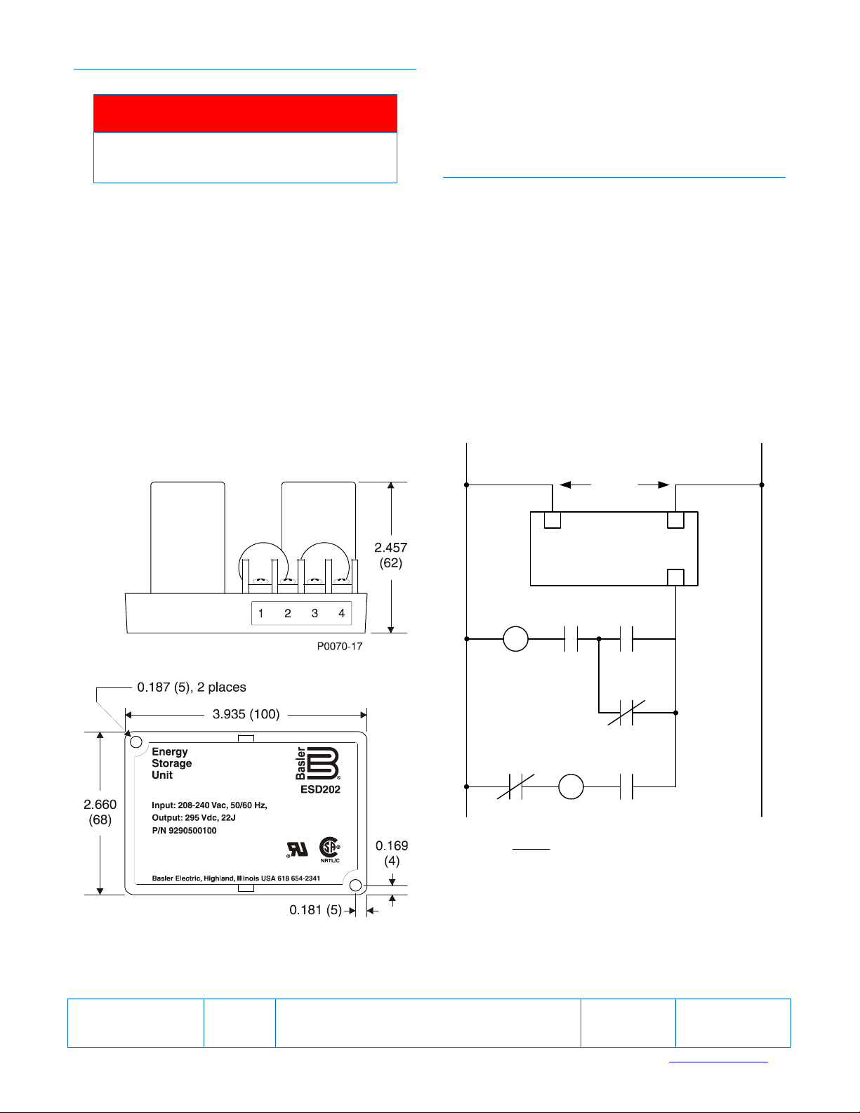
Connections
Typical ESD202 connections are shown in Figure 2.
ESD202 terminals accommodate a maximum wire
size of 12 AWG (3.31 mm
2
). The terminal screws have
a maximum torque rating of 9 in-lb (1 Nm).
STORAGE AND MAINTENANCE
An ESD202 should be used with a single circuit
breaker. Control of more than one breaker (or other
devices) by a single ESD202 is not recommended. If
control of more than one breaker is desired, it must be
demonstrated, through independent testing, that
combinations of breakers (or other devices) can be
reliably operated from a single ESD202.
Mounting
ESD202 mounting dimensions are illustrated in Figure
1. Dimensions are given in inches with millimeters in
parenthesis.
This device contains long-life, aluminum electrolytic
capacitors. For devices that are not in service (spares
in storage), the life of these capacitors can be
maximized by energizing the device for 30 minutes
once per year.
No maintenance of the ESD202 is required other than
periodically checking that all connections are clean
and tight. The ESD202 is not field repairable. If repairs
are required, return the ESD202 to Basler Electric.
240 Vac
14
ESD202
3
Figure 1. ESD202 Mounting Dimensions
52TC
Legend
50/51: Overcurrent Relay
52: Power Circuit Breaker
86: Lockout Relay
a: Breaker Auxiliary Contact
CS/T: Control Switch, Trip
Figure 2. ESD202 Typical Connections
86
52 CS/T52a
86
50/5186
P0070-18
Publication
9290500990
For terms of service relating to this product and software, see the Commercial Terms of Products and Servicesdocument available at www.basler.com/terms.
Revision
B
Instruction
Date
10/12
Page
2 of 2
 Loading...