

Page 1
s
www.basler.com
+1 618.654.2341 (USA)
info@basler.com
INTRODUCTION
The Energy Storage Device (ESD 201) is used where a
station battery source is not available to provide circuit
breaker trip power. The ESD 201 converts ac bus voltage
to dc and stores enough energy to trip a circuit breaker one
time for up to 72 hours after ac power has been interrupted.
Warning!
To prevent personal injury or equipment damage,
only qualified technicians or operators should
install, operate, or service this device.
Caution
The ESD 201 is not a power supply and can be
damaged by continuous current draw on the
output.
ELECTRICAL SPECIFICATIONS
Output Power
330 to 430 Vdc
27 joules minimum at 330 Vdc
36 joules minimum at 380 Vdc
46 joules minimum at 430 Vdc
This output is maintained for 72 hours after the internal
battery is fully charged.
Power Input
Operating Range: 120 or 240 Vac, ±10%, single-
phase, 50/60 Hz
Burden: 10 VA maximum
Charging Rate
Varies nonlinearly from 90 volts/cycle down to 2.8 volts
minimum as capacitor approaches 90% full charge after
breaker trip event.
Power Dissipation
2.0 W maximum, continuous
PHYSICAL SPECIFICATIONS
Operating Temperature
–25°C to 65°C (–13°F to 149°F)
Storage Temperature
–40°C to 85°C (–40°F to 185°F)
Vibration
Withstands 2 G at 10 to 200 Hz in each of three mutually
perpendicular axes.
Model
Part Number
Shock
Withstands 15 G in each of three mutually perpendicular
axes.
Dimensions
Refer to Figure 3.
Weight
0.59 kg (1.3 lb)
Agency Certification/Recognition
Meets CSA C22.2, Number 14, Industrial Control
Equipment.
Meets UL 508, Industrial Control Equipment as tested by
CSA NRTL.
ESD 201
9110600101
THEORY OF OPERATION
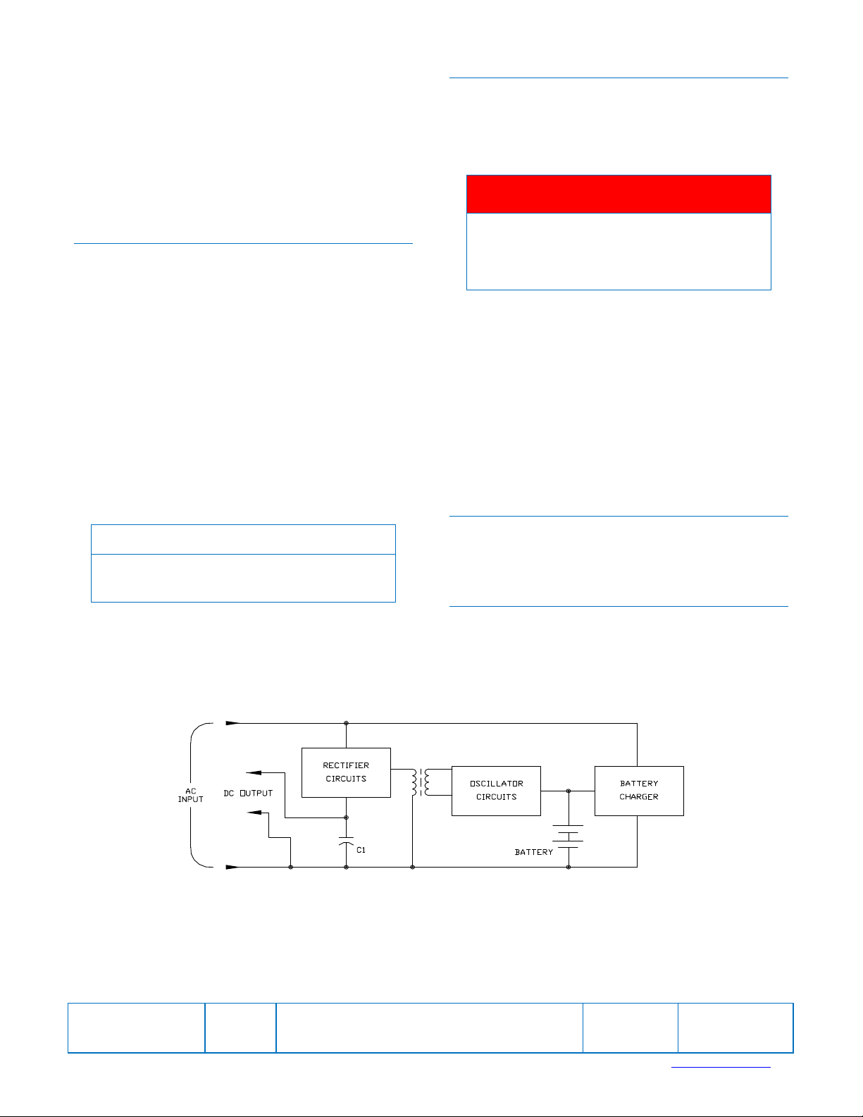
ESD 201 operation is illustrated in Figure 1. Power input to
the ESD 201 is 120 or 240 Vac. This input is rectified and
used to charge the output capacitor (C1) to approximately
330 Vdc. As long as the ac input is applied, C1 continues to
be charged in this manner. However, the failure of the ac
input is what the ESD 201 is designed to protect against.
Therefore, when the ac input fails, a battery powered
oscillator circuit and an associated step-up transformer act
as the C1 charging source. (The ESD 201 can be
interconnected to the system so that the oscillator circuits
function only when the breaker being controlled is closed.
See Figure 2.) A battery charger charges the batteries as
long as the ac input is applied to the ESD 201.
CONTROLS AND INDICATORS
The pushbutton and LED indicator are used to determine if
the ESD 201 is operationally ready. When the button is
pushed, the LED lights if the capacitor has the minimum
charge of 180 Vdc required to trip the breaker. The
pushbutton and LED do not indicate whether the ac input is
being applied.
Note
The test circuit acts as a discharge path to the
output capacitor. Therefore, the pushbutton should
be depressed only long enough to observe if the
LED lights.
INSTALLATION
The ESD 201 should be connected as shown in Figure 2.
In order for the ESD 201 internal, battery-operated,
capacitor-charging circuits to operate, terminal 1 must be
connected to terminal 4. This can be accomplished by
permanently jumpering the two terminals together. Using
this approach however, the oscillator circuits will continually
be in operation if the battery is in place. This will result in
premature discharge of the battery if ac input power is not
being applied. An alternate (and preferable) approach
Publication
9110600991
For terms of service relating to this product and software, see the Commercial Terms of Products and Servicesdocument available at www.basler.com/terms.
Revision
F
Instruction
Date
09/12
Copyright
2012
Page 2
s
involves the use of the breaker auxiliary “a” contact. The
intent of the “a” contact is to inhibit operation of the
oscillator circuit (and thereby eliminate battery drain) until
the circuit breaker is closed.
Each breaker should be equipped with its own ESD 201.
The use of a single ESD 201 to provide a tripping output for
more than one breaker (or other device) is not
recommended. Such configurations should be considered
only when it can be demonstrated, through independent
testing, that combinations of breakers (or devices) can be
reliably operated from a single ESD 201.
OPERATION
When the ESD 201 is properly interconnected and 120 or
240 Vac input power is applied, the unit is ready for
operation. This can be verified by using the pushbutton as
described in the Controls and Indicators paragraph. No
adjustments of any type should be necessary.
AC power must be applied continually for a minimum of two
hours before the ESD 201 is capable of developing full
charge on the output capacitor with a sustained interruption
in ac input.
If the batteries are fully discharged (terminal voltage of 3.6
volts or less), it will take approximately 48 hours to
recharge the batteries from the ac source. In such
situations, it is suggested that the batteries be removed
and recharged with a high rate charger (not to exceed a
0.1-ampere charging rate). During this time, rechargeable
NiCd “AA” size cells (Basler Electric P/N 31129) should be
substituted in the ESD 201.
Note
Read the paragraphs under Discharging before
changing batteries.
DISCHARGING
Since more than 400 Vdc can be present on the ESD 201
output terminals, the storage capacitors should be
discharged before working on the unit. The following
procedure can be used for discharging the storage
capacitors.
Warning!
Lethal voltage may be present at ESD 201
terminals and within the ESD 201. Only qualified
persons should install, operate, or service this
device.
1. Connect a few inches of 14 AWG, 600 V insulated wire
to each end of a 470 Ω, 5 W, wire-would resistor.
2. Remove ac input power from ESD 201 terminals 1, 5,
and 2.
3. To discharge the capacitors, carefully touch one of the
resistor wires to terminal 1 and the other wire to
terminal 3. Hold the wires on the terminals for at least
five seconds.
4. Ensure that the capacitors are discharged by
connecting a dc voltmeter across terminals 3 (+) and 1
(–).
STORAGE
This device contains long-life aluminum electrolytic
capacitors. For devices that are not in service (spares in
storage), the life of these capacitors can be maximized by
energizing the device for 30 minutes once per year.
REPAIRS
The ESD 201 is not field repairable. Should the device
require repairs, return it to Basler Electric for service.
D2751-11
Figure 1. Function Block Diagram
Publication
9110600991
For terms of service relating to this product and software, see the Commercial Terms of Products and Servicesdocument available at www.basler.com/terms.
Revision
F
Instruction
Date
09/12
Page
2 of 4
Page 3

s
Figure 2. Interconnection Diagram
D2751-09
D2751-10
Figure 3. Outline Drawing
Publication
9110600991
For terms of service relating to this product and software, see the Commercial Terms of Products and Servicesdocument available at www.basler.com/terms.
Revision
F
Instruction
Date
09/12
Page
3 of 4
Page 4

s
9110600991
Publication
Revision
F
Instruction
Date
09/12
Page
4 of 4
For terms of service relating to this product and software, see the Commercial Terms of Products and Servicesdocument available at www.basler.com/terms.
 Loading...