

Page 1
INSTRUCTION MANUA L
FOR
DGC-2020HD
DIGITAL GENSET CONTROLLE R
Publication: 9469300990
Revision: B Mar-14
Page 2

Page 3

9469300990 Rev B i
Caution
Note
Preface
This instruction manual provides information about the installation and operation of the DGC-2020HD
Digital Genset Controller. To accomplish this, the following information is provided:
• Controls and indicators
• Inputs and outputs
• Protection and control functions
• Reporting and alarms information
• Mounting and connection diagrams
• BESTCOMSPlus
• Communication and security
• Maintenance and troublesh ooting pr oc edures
• Specifications
• AEM-2020
• CEM-2020
• MTU Fault Codes
• Exhaust Treatment
• Diagnostic Trouble Codes
Conventions Used in this Ma nua l
®
software
Important safety and procedural information is emphasized and presented in this manual through
Warning, Caution, and Note boxes. Each type is illustrated and defined as follows.
Warning!
Warning boxes call attention to conditions or actions that may cause
personal injury or death.
Caution boxes call attention to operating conditions that may lead to
equipment or property damage.
Note boxes emphasize important information pertaining to Digital
Genset Controller installation or operation.
Digital Genset Controller Preface
Page 4

ii 9469300990 Rev B
Basler Electric does not assume any responsibility to compliance or noncompliance with national code, local code,
This product contains, in part, open source software (software licensed in a way that ensures freedom to run,
terms of either the GNU General Public License or GNU Lesser General Public License. The licenses, at the time
documentation from us, including our End User License Agreement, places any additional restrictions on what you
corresponding source code for the version of the programs distributed to you will be sent upon request (contact
The source code is distributed in the hope that it will be useful, but WITHOUT ANY REPRESENTATION or
Review the software website for the latest version of the software documentation.
For terms of service relating to this product and software, see the Commercial Terms of Products and Services
document available at www.basler.com/terms.
It is not the intention of this manual to cover all details and variations in equipment, nor does this manual provide
manual.
The English-language version of this manual serves as the only approved manual version.
12570 State Route 143
Highland IL 62249-1074 USA
www.basler.com
info@basler.com
Tel: +1 618.654.2341
Fax: +1 618.654.2351
© 2014 by Basler E lectric
All rights reserved
First printing: November 2013
Warning!
READ THIS MANUAL. Read this manual before installing, operating, or maintaining the DGC-2020HD.
Note all warnings, cautions, and notes in this manual as well as on the product. Keep this manual with
the product for reference. Only qualified personnel should install, operate, or service this system.
Failure to follow warning and cautionary labels may result in personal injury or property damage.
Exercise caution at all times.
or any other applicable code. This manual serves as reference material that must be well understood prior to
installation, operation, or maintenance.
copy, distribute, study, change, and improve the software) and you are granted a license to that software under the
of sale of the product, allow you to freely copy, modify, and redistribute that software and no other statement or
may do with that software.
For at least three (3) years from the date of distribution of this product, a machine-readable copy of the complete
information is provided above). A fee of no more than our cost of physically performing the source code distribution
is charged.
WARRANTY or even the implied warranty of MERCHANTABILITY or FITNESS FOR A PARTICULAR PURPOSE.
Refer to the source code distribution for additional restrictions regarding warranty and copyrights.
For a complete copy of GNU GENERAL PUBLIC LICENSE Version 2, June 1991 or GNU LESSER GENERAL
PUBLIC LICENSE Version 2.1, February 1999 refer to www.gnu.org or contact Basler Electric. You, as a Basler
Electric Company customer, agree to abide by the terms and conditions of GNU GENERAL PUBLIC LICENSE
Version 2, June 1991 or GNU LESSER GENERAL PUBLIC LICENSE Version 2.1, February 1999, and as such
hold Basler Electric Company harmless related to any open source software incorporated in this product. Basler
Electric Company disclaims any and all liability associated with the open source software and the user agrees to
defend and indemnify Basler Electric Company, its directors, officers, and employees from and against any and all
losses, claims, attorneys' fees, and expenses arising from the use, sharing, or redistribution of the software.
data for every possible contingency regarding installation or operation. The availability and design of all features
and options are subject to modification without notice. Over time, improvements and revisions may be made to this
publication. Before performing any of the following procedures, contact Basler Electric for the latest revision of this
Preface DGC-2020HD
Page 5

9469300990 Rev B iii
Contents
Introduction ................................................................................................................................................. 1
Features and Functions ............................................................................................................................. 1
Style Number ............................................................................................................................................. 4
Optional Features and Capabilities ........................................................................................................... 4
Specifications .............................................................................................................................................. 5
Operating Power ........................................................................................................................................ 5
Battery Ride Through ................................................................................................................................ 5
Current Sensing ......................................................................................................................................... 5
Voltage Sensing ........................................................................................................................................ 5
Analog Sensing ......................................................................................................................................... 6
Contact Sensing ........................................................................................................................................ 6
Engine System Inputs................................................................................................................................ 7
Output Contacts ......................................................................................................................................... 7
Metering ..................................................................................................................................................... 8
Generator Protection Functions .............................................................................................................. 10
Logic Timers ............................................................................................................................................ 11
Communication Interface......................................................................................................................... 11
Real-Time Clock ...................................................................................................................................... 12
LCD Heater .............................................................................................................................................. 13
Type Tests ............................................................................................................................................... 13
Environment ............................................................................................................................................ 13
UL Approval ............................................................................................................................................. 14
CSA Certification ..................................................................................................................................... 14
NFPA Compliance ................................................................................................................................... 14
CE Compliance ........................................................................................................................................ 14
Physical ................................................................................................................................................... 14
Mounting .................................................................................................................................................... 15
Hardware ................................................................................................................................................. 15
Dimensions .............................................................................................................................................. 15
Terminals and Connectors ....................................................................................................................... 17
Terminals ................................................................................................................................................. 18
Connectors .............................................................................................................................................. 25
Typical Applications ................................................................................................................................. 27
Connections for Typical Applications ...................................................................................................... 27
Connections for Load Sharing ................................................................................................................. 32
Analog Input Connections ....................................................................................................................... 33
CAN Connections .................................................................................................................................... 33
Expansion Module Connections (CAN 1) ................................................................................................ 35
Installation for CE Systems ..................................................................................................................... 35
Controls and Indicators ............................................................................................................................ 37
Programmable Indicator Configuration .................................................................................................... 39
Display Operation and Navigation ........................................................................................................... 40
Display Setup .......................................................................................................................................... 48
Power Input ................................................................................................................................................ 51
Nominal Voltage Input and Acceptable Range of Input Voltage ............................................................. 51
Terminal Assignments ............................................................................................................................. 51
Power Consumption ................................................................................................................................ 51
Battery Ride-Through Capability ............................................................................................................. 51
Fuse Protection ....................................................................................................................................... 51
Voltage and Current Sensing ................................................................................................................... 53
Generator Voltage ................................................................................................................................... 53
DGC-2020HD Contents
Page 6

iv 9469300990 Rev B
Bus Voltage ............................................................................................................................................. 53
Generator and Bus Current ..................................................................................................................... 53
Engine Sender Inputs ............................................................................................................................... 55
Connections ............................................................................................................................................. 55
Compatibility ............................................................................................................................................ 55
Operation ................................................................................................................................................. 55
Programmability ....................................................................................................................................... 55
Characteristic Curves .............................................................................................................................. 55
Sender Failure Detection ......................................................................................................................... 59
Speed Signal Inputs .................................................................................................................................. 61
Magnetic Pickup ...................................................................................................................................... 61
Generator Sensing Voltage ..................................................................................................................... 61
Contact Inputs ........................................................................................................................................... 63
Programmable Contact Inputs ................................................................................................................. 63
Analog Inputs ............................................................................................................................................ 67
Input Setup .............................................................................................................................................. 67
Ranges .................................................................................................................................................... 67
Thresholds ............................................................................................................................................... 67
Operational Settings ................................................................................................................................ 68
Logic Connections ................................................................................................................................... 69
Contact Outputs ........................................................................................................................................ 71
Prestart .................................................................................................................................................... 71
Start ......................................................................................................................................................... 71
Run .......................................................................................................................................................... 71
Relay Control ........................................................................................................................................... 71
Programmable Contact Outputs .............................................................................................................. 72
Operating Modes ....................................................................................................................................... 75
Off ............................................................................................................................................................ 75
Run .......................................................................................................................................................... 75
Auto ......................................................................................................................................................... 75
Operating Mode Control .......................................................................................................................... 75
Breaker Management ................................................................................................................................ 77
Breaker Status ......................................................................................................................................... 77
System Breaker Configuration ................................................................................................................ 77
Breaker Operation ................................................................................................................................... 88
Synchronizer ............................................................................................................................................. 97
Operation ................................................................................................................................................. 97
Configuration ........................................................................................................................................... 99
Bias Control ............................................................................................................................................. 113
AVR Bias Control Settings .................................................................................................................... 113
Governor Bias Control Settings ............................................................................................................. 115
Multiple Generator Management ........................................................................................................... 119
AVR Output ........................................................................................................................................... 119
Governor Output .................................................................................................................................... 120
Load Share Output ................................................................................................................................ 121
Parameter Selection .............................................................................................................................. 121
Demand Start/Stop ................................................................................................................................ 121
Generator Sequencing .......................................................................................................................... 123
Network Configuration ........................................................................................................................... 125
Generator Protection .............................................................................................................................. 127
Undervoltage (27) .................................................................................................................................. 127
Overvoltage (59) .................................................................................................................................... 129
Contents DGC-2020HD
Page 7

9469300990 Rev B v
Phase Voltage Imbalance (47) .............................................................................................................. 131
Vector Shift (78) ..................................................................................................................................... 133
Frequency (81) ...................................................................................................................................... 135
Overcurrent (51) .................................................................................................................................... 138
Power (32) ............................................................................................................................................. 144
Loss of Excitation (40Q) ........................................................................................................................ 147
Setting Groups ....................................................................................................................................... 149
Configurable Protection ......................................................................................................................... 151
Element Setup ....................................................................................................................................... 151
Thresholds ............................................................................................................................................. 153
Logic Connections ................................................................................................................................. 154
Operational Settings .............................................................................................................................. 154
Metering ................................................................................................................................................... 157
Metering Explorer .................................................................................................................................. 157
Engine.................................................................................................................................................... 158
Generator .............................................................................................................................................. 159
Bus 1 and Optional Bus 2 ...................................................................................................................... 159
Bias Control ........................................................................................................................................... 160
Power..................................................................................................................................................... 160
Run Statistics ......................................................................................................................................... 161
Synchronization ..................................................................................................................................... 161
Status Indication .................................................................................................................................... 162
Inputs ..................................................................................................................................................... 162
Outputs .................................................................................................................................................. 167
Configurable Protection ......................................................................................................................... 169
J1939 ECU ............................................................................................................................................ 169
MTU ....................................................................................................................................................... 171
Summary ............................................................................................................................................... 172
Control Panel ......................................................................................................................................... 174
Generator Network Status ..................................................................................................................... 174
Generator Sequencing .......................................................................................................................... 175
Diagnostics ............................................................................................................................................ 176
Analysis ................................................................................................................................................. 176
Reporting and Alarms ............................................................................................................................. 179
Event Logging ........................................................................................................................................ 179
Sequence of Events .............................................................................................................................. 179
Data Logging ......................................................................................................................................... 180
Trending ................................................................................................................................................ 181
Alarms.................................................................................................................................................... 182
BESTCOMSPlus® Software .................................................................................................................... 193
System Recommendations ................................................................................................................... 194
Installation ............................................................................................................................................. 194
Activate the DGC-2020HD Plugin for BESTCOMSPlus® ...................................................................... 194
Menu Bars ............................................................................................................................................. 198
Settings Explorer ................................................................................................................................... 199
Metering Explorer .................................................................................................................................. 200
BESTspace™ ......................................................................................................................................... 200
Settings File Management ..................................................................................................................... 201
Auto Export Metering ............................................................................................................................. 202
BESTCOMSPlus® Updates ................................................................................................................... 203
Firmware Updates ................................................................................................................................. 203
BESTlogic™Plus ...................................................................................................................................... 205
Overview of BESTlogic™Plus ................................................................................................................ 205
BESTlogic™Plus Composition ............................................................................................................... 206
Logic Schemes ...................................................................................................................................... 234
DGC-2020HD Contents
Page 8

vi 9469300990 Rev B
Programming BESTlogic ™Plus.............................................................................................................. 235
Offline Logic Simulator .......................................................................................................................... 236
BESTlogic™Plus File Management ....................................................................................................... 236
BESTlogic™Plus Ex amp les ................................................................................................................... 237
Communication ....................................................................................................................................... 239
USB ....................................................................................................................................................... 239
Ethernet ................................................................................................................................................. 239
CAN ....................................................................................................................................................... 243
RS-232 .................................................................................................................................................. 253
RS-485 .................................................................................................................................................. 256
Modbus™ Setup ..................................................................................................................................... 256
Remote Display Panel (optional) ........................................................................................................... 257
Configuration ........................................................................................................................................... 259
System Settings ..................................................................................................................................... 259
Rated Data ............................................................................................................................................ 262
Remote Module Setup ........................................................................................................................... 267
Crank Settings ....................................................................................................................................... 267
Automatic Restart Settings .................................................................................................................... 269
Exercise Timer Settings......................................................................................................................... 270
Sensing Transformer Ratings ................................................................................................................ 271
Relay Control Settings ........................................................................................................................... 272
System Configuration Detection Settings .............................................................................................. 273
Device Information .................................................................................................................................. 275
Style Number ......................................................................................................................................... 275
Device Info ............................................................................................................................................. 275
Firmware Updates ................................................................................................................................. 276
Security .................................................................................................................................................... 281
Access Levels ........................................................................................................................................ 281
User Name Setup .................................................................................................................................. 281
Port Access Setup ................................................................................................................................. 283
Access Control ...................................................................................................................................... 283
Timekeeping ............................................................................................................................................ 285
Clock Setup ........................................................................................................................................... 285
Setting the Time and Date ..................................................................................................................... 287
IRIG Port ................................................................................................................................................ 287
Real-Time Clock Specificat ions ............................................................................................................. 288
Backup Battery for the Real-Time Clock ............................................................................................... 288
Maintenance and Troubleshooting ....................................................................................................... 289
Maintenance .......................................................................................................................................... 289
Storage .................................................................................................................................................. 289
Troubleshooting ..................................................................................................................................... 289
AEM-2020 ................................................................................................................................................. 303
Features ................................................................................................................................................ 303
Specifications ........................................................................................................................................ 303
Functional Description ........................................................................................................................... 305
Mounting ................................................................................................................................................ 305
Connections ........................................................................................................................................... 306
AEM-2020 Configuration ....................................................................................................................... 312
Remote Analog Inputs Configuration .................................................................................................... 312
Remote RTD Inputs Configuration ........................................................................................................ 315
Remote Thermocouple Inputs Configuration ........................................................................................ 317
Remote Analog Outputs Configuration .................................................................................................. 319
Firmware Updates ................................................................................................................................. 322
Repair .................................................................................................................................................... 322
Contents DGC-2020HD
Page 9

9469300990 Rev B vii
Maintenance .......................................................................................................................................... 322
Storage .................................................................................................................................................. 323
CEM-2020 ................................................................................................................................................. 325
Features ................................................................................................................................................ 325
Specifications ........................................................................................................................................ 325
Functional Description ........................................................................................................................... 327
Mounting ................................................................................................................................................ 327
Connections ........................................................................................................................................... 329
CEM-2020 Configuration ....................................................................................................................... 334
Remote Contact Inputs Configuration ................................................................................................... 334
Remote Contact Outputs Configuration ................................................................................................ 336
Firmware Updates ................................................................................................................................. 336
Repair .................................................................................................................................................... 336
Maintenance .......................................................................................................................................... 337
Storage .................................................................................................................................................. 337
Time Curve Characteristics.................................................................................................................... 339
Curve Specifications .............................................................................................................................. 339
Time Overcurrent Characteristic Curve Graphs .................................................................................... 340
Tuning PID Settings ................................................................................................................................ 361
Voltage and Speed Controllers ............................................................................................................. 361
kW Load Controller ................................................................................................................................ 361
Var/PF Controller ................................................................................................................................... 361
Speed Trim Function ............................................................................................................................. 361
Tuning Parameters ................................................................................................................................ 361
Tuning Procedures ................................................................................................................................ 362
Generic Gains for Multiple Machine Types ........................................................................................... 366
MTU Fault Codes ..................................................................................................................................... 367
Exhaust Treatment .................................................................................................................................. 377
Diesel Particulate Filter (DPF) ............................................................................................................... 377
Exhaust After-Treatment Systems (EATS)............................................................................................ 379
Diagnostic Trouble Codes ...................................................................................................................... 381
Revision History ...................................................................................................................................... 391
DGC-2020HD Contents
Page 10

viii 9469300990 Rev B
Contents DGC-2020HD
Page 11

9469300990 Rev B 1
Introduction
The DGC-2020HD Digital Genset Controller provides integrated engine-genset control, protection, and
metering in a single package. Microprocessor based technology allows for exact measurement, setpoint
adjustment, and timing functions. Front panel controls and indicators enable quick and simple DGC2020HD operation. A backlit liquid crystal display (LCD) can be viewed under a wide range of ambient
light and temperature conditions. Basler Electric communication software (BESTCOMSPlus®) allows units
to be easily customized for each application. Because of the low sensing burden in the DGC-2020HD,
dedicated potential transformers (PTs) are not required.
Features and Functions
The DGC-2020HD Digital Genset Controller has the following features:
• Local and remote generator control
• Engine, generator, and loss of mains protection (optional)
• Automatic transfer switch control (mains failure)
• Automatic generator configuration detection
• Generator sequencing
• Generator soft loading/unloading
• Auto synchronizing (optional)
• Programmable analog engine senders
• 16 programmable contact inputs
• Three programmable front panel LEDs, with labels
• Up to four local analog inputs
• A ramping function to load and unload generator smoothly
• Demand start/stop and generator sequencing
• kW and kvar load control
• kW and kvar load sharing via Ethernet or analog load share lines
• Programmable logic
• Exercise timer
• ECU communications via SAE J1939
• Marathon DVR2000E+ voltage regulator control via SAE J1939
• Integrated USB, RS485, and Ethernet communication
• Two J1939 CAN Bus ports
• Additional modules available to expand the capabilities of the DGC-2020HD
An overview of DGC-2020HD Digital Genset Controller functions is provided in the following paragraphs.
Generator and Bus Protection and Metering
Multifunction protection guards against overvoltage, undervoltage, excessive forward and reverse power,
underfrequency, and overfrequency. Overcurrent, phase imbalance, loss of mains, and frequency rate-ofchange protection are available as an option. Each protection function has an adjustable pickup and time
delay setting. Sixteen inverse time curves, in addition to user-programmable curves, enable the DGC2020HD to offer overcurrent protection in a variety of applications. Each protective element can be
assigned to the generator, bus 1 or bus 2.
Metered generator and bus parameters include voltage, current, real power (watts), apparent power (VA),
and power factor (PF).
Engine Protection and Metering
Engine protection features include oil pressure and coolant temperature monitoring, overcrank protection,
ECU-specific protection elements, and diagnostic reporting.
Metered engine parameters include oil pressure, coolant temperature, battery voltage, speed, fuel level,
engine load, coolant level (from ECU), ECU-specific parameters, and run-time statistics.
DGC-2020HD Introduction
Page 12

2 9469300990 Rev B
Load Sharing
The DGC-2020HD provides analog outputs to the power system in the form of analog bias signals to the
voltage regulator and speed governor. A pulse width modulated (PWM) speed bias output is also
available. When the generator breaker is closed and load sharing is enabled, the DGC-2020HD shares
the real power load proportionally with other generators in the system. Load sharing can be implemented
on the Analog Load Share Line or through Ethernet communications. Reactive power (kvar) sharing is
accomplished through Ethernet communications.
Event Recording
A history of system events are logged in nonvolatile memory. The DGC-2020HD retains records for 128
unique types of events. Each record tracks the number of times that an event has occurred and records a
time stamp of the first and last occurrences.
A Sequence of Events (SER) log is also available. This log tracks the internal and external status of the
DGC-2020HD. Events are scanned at five millisecond intervals with 1,023 events stored per record. All
changes of state that occur during each scan are time- and date-stamped. Sequences of Events reports
are available through BESTCOMSPlus. Over 1,000 records can be retained in nonvolatile memory. When
the SER memory becomes full, the oldest record is replaced by the latest one acquired.
Data Logging
The data logging function of the DGC-2020HD records up to six records of user-selectable, real-time
parameter data. For more information, see the Reporting and Alarms chapter.
Contact Inputs and Outputs
DGC-2020HD controllers have 16 programmable contact inputs. All contact inputs recognize dry contacts.
The programmable inputs can be configured to initiate a pre-alarm or alarm condition. A programmable
input can be programmed to receive a contact input from an automatic transfer switch (ATS). In addition,
a programmable Battle Override function allows overriding of DGC-2020HD alarms and protection
functions. Each programmable input can be assigned a user-defined name for easy identification at the
front panel display and in fault records.
Output contacts include three dedicated relays for energizing an engine’s glow plugs, fuel solenoid, and
starter solenoid. An additional twelve programmable output contacts are provided.
Additional contact inputs and output contacts can be accommodated with an optional CEM-2020 Contact
Expansion Module. Contact Basler Electric for ordering information.
Automatic Transfer Switch Control (Mains Failure)
The DGC-2020HD has the ability to detect a mains failure via a single- or three-phase Bus input. A mains
failure is established when any one of the following conditions are met:
• Any phase of bus voltage falls below the dead bus threshold
• Any phase of bus voltage is unstable due to overvoltage or undervoltage
• Any phase of bus voltage is unstable due to overfrequency or underfrequency
At this time, the DGC-2020HD starts the genset and, when ready, applies power to the load from the
genset. The DGC-2020HD implements open or closed breaker transitions to and from the mains. When
the mains returns and is considered stable, the DGC-2020HD will transfer the load back to the mains and
stop the engine. During closed breaker transitions, the optional Auto Synchronizer can synchronize the
generator to the mains before transferring the load from generator power to utility power.
Device Security
Passwords provide access security for six distinct functional access areas: Read, Control, Operator,
Settings, Design, and Administrator. Each username/password is assigned an access area with access to
that area and each area below it. An administrator password provides access to all six of the functional
areas.
Introduction DGC-2020HD
Page 13

9469300990 Rev B 3
A second dimension of security is provided by the ability to restrict access for any of the access areas to
only specific communication ports. For example, you could set up security to deny access to control
commands through an Ethernet port.
Security settings affect read and write access. Refer to the Security chapter for more information.
Communication
DGC-2020HD communication features include a mini-B USB port, RS-485 port, two copper Ethernet ports
or one fiber optic Ethernet port (optional), and SAE J1939 interface.
USB Port
The USB communication port can be used with BESTCOMSPlus® software to quickly configure a DGC2020HD with the desired settings or retrieve metering values and event log records.
RS485 Port
An RS485 communication port uses the Modbus™ communication protocol and enables remote control
and monitoring of the DGC-2020HD over a polled network.
Ethernet Port(s)
Depending on style number, each DGC-2020HD is equipped with either dual copper (100BaseT) Ethernet
communication ports (style xxxxDxxxx) or a fiber optic (100BaseF) Ethernet communication port (style
xxxxFxxxx).
Ethernet ports provide communications between the DGC-2020HD and a PC via BESTCOMSPlus or
other DGC-2020HDs in a network. An Ethernet connection to a PC running BESTCOMSPlus provides
remote metering, setting, annunciation, and control of the DGC-2020HD. Ethernet communication
between DGC-2020HDs allows for generator sequencing on an islanded system.
CAN Interface
The CAN (Control Area Network) interface provides high-speed communication between the DGC2020HD and the engine control unit (ECU) on an electronically controlled engine. This interface provides
access to oil pressure, coolant temperature, and engine speed data by reading these parameters directly
from the ECU. When available, engine diagnostic data can also be accessed. The CAN interface supports
the following protocols:
• SAE J1939 Protocol - Oil pressure, coolant temperature, and engine speed data are received
from the ECU. In addition, DTCs (Diagnostic Trouble Codes) help diagnose any engine-related
failures. The engine DTCs are displayed on the front panel of the DGC-2020HD and may be
obtained using BESTCOMSPlus® software.
• MTU Protocol - A DGC-2020HD connected to a genset equipped with an MTU engine ECU
receives Oil pressure, coolant temperature, and engine speed data from the engine controller,
along with various alarms and pre-alarms that are MTU-specific. In addition, the DGC-2020HD
tracks and displays the active fault codes issued by the MTU engine ECU.
DGC-2020HD Introduction
Page 14
4 9469300990 Rev B
MODEL NUMBER
STYLE NUMBER
DGC – 2020HD
P0071-69
Current Sensing
5) 5A CT inputs
1) 1A CT inputs
N N
Generator Protection
,
S) Standard: 27, 32, 40Q,
59 81O, 81U
E) Enhanced: 27, 32, 40Q,
47, 51, 59, 78, 81O,
81U, 81 ROCOF
Ethernet
D) Dual 100BaseT (Copper)
F) 100BaseF (Fiber)
Terminal Type
S) Spring
Auto Synchronizer
1) No Auto Sync
2) w/ Auto Sync
The fuel level sender is always resistive and is not a programmable input.
1
Senders
A) Anal og
R) Resi st ive
1
Bus Inputs
B) Basic Sensing:
1 Bus Input, 4 CTs
E) Enhanced Sensing:
2 Bus Inputs, 7 CTs
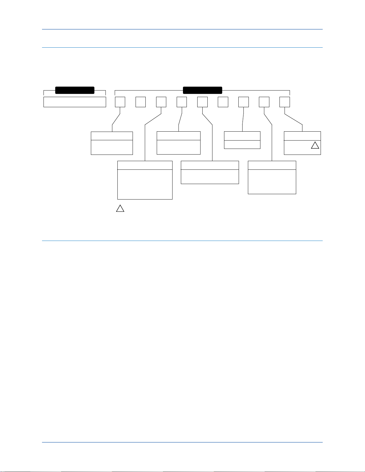
Style Number
Standard-order DGC-2020HD controllers are identified by a style number which consists of a combination
of letters and numbers that define the controller’s electrical characteristics and operational features. The
model number, together with the style number, describes the options included in a specific controller.
Figure 1 illustrates the DGC-2020HD style number identification chart.
Optional Features and Capabilities
AEM-2020 (Analog Expansion Module)
The optional AEM-2020 provides eight remote analog inputs, eight remote RTD inputs, two Type-K
remote thermocouple inputs, and four remote analog outputs to the DGC-2020HD. The AEM-2020
communicates with the DGC-2020HD through a CAN interface. Up to four AEM-2020s may be used with
one DGC-2020HD. Refer to the AEM-2020 chapter for more information.
CEM-2020 (Contact Expansion Module)
The optional CEM-2020 provides 10 additional contact inputs and 18 or 24 additional output contacts
(depending on module type) to the DGC-2020HD. The CEM-2020 communicates with the DGC-2020HD
through a CAN interface. Up to four CEM-2020s may be used with one DGC-2020HD. Refer to the CEM-
2020 chapter for more information.
Figure 1. DGC-2020HD Style Chart
Introduction DGC-2020HD
Page 15

9469300990 Rev B 5
Specifications
DGC-2020HD electrical and physical characteristics are listed in the following paragraphs.
Operating Power
Nominal ............................................ 12 or 24 Vdc
Range ............................................... 6 to 32 Vdc
Terminals.......................................... 48 (+), 49 (–), 50 (chassis ground)
Power Consumption
Sleep Mode ...................................... 12.7 W - LCD heater off, all relays de-energized, and analog outputs
disabled
Normal Operational Mode ................ 18.1 W - Run mode, LCD heater off, START and RUN relays
energized, six programmable relays energized, and analog outputs
enabled
Maximum Operational Mode ............ 25 W - Run mode, LCD heater on, all relays energized, and analog
outputs enabled
Battery Ride Through
Starting at 10 Vdc, withstands cranking ride-through down to 0 Vdc for 50 ms
Current Sensing
Burden .............................................. 1 VA
Generator CTs
Terminals.......................................... 1 (+), 2 (–) (A-phase)
3 (+), 4 (–) (B-phase)
5 (+), 6 (–) (C-phase)
Available Programmable CTs
AUX 1Terminals ............................... 7 (+), 8 (–)
AUX 2 Terminals .............................. 9 (+), 10 (–)
AUX 3 Terminals .............................. 11 (+), 12 (–)
AUX 4 Terminals .............................. 13 (+), 14 (–)
(Programmable CTs AUX 2, 3, and 4 are optional with style number xxxxxxxEx.)
1 Aac Current Sensing
Continuous Rating ............................ 0.02 to 1.5 Aac
1 Second Rating ............................... 10 Aac
5 Aac Current Sensing
Continuous Rating ............................ 0.1 to 7.5 Aac
1 Second Rating ............................... 50 Aac
Voltage Sensing
Range ............................................... 12 to 576 V rms, line-to-line
Frequency ........................................ 50/60 Hz
Frequency Range ............................. 10 to 90 Hz
Burden .............................................. 1 VA
1 Second Rating ............................... 720 V rms
DGC-2020HD Specifications
Page 16

6 9469300990 Rev B
Generator Sensing
Configuration .................................... Line-to-line or line-to-neutral
Generator Sensing Terminals .......... 86 (A-phase)
88 (B-phase)
90 (C-phase)
91 (Neutral)
Bus 1 Sensing
Configuration .................................... Line-to-line or line-to-neutral
Bus Sensing Terminals .................... 93 (A-phase)
95 (B-phase)
97 (C-phase)
98 (Neutral)
Bus 2 Sensing (Optional with style number xxxxxxxEx)
Configuration .................................... Line-to-line or line-to-neutral
Bus Sensing Terminals .................... 100 (A-phase)
101 (B-phase)
103 (C-phase)
104 (Neutral)
Analog Sensing
The DGC-2020HD contains two or four (optional) analog inputs.
Current Sensing
Rating ............................................... 4 to 20 mA
Burden .............................................. 84.25 Ω to 87.1 Ω
Voltage Sensing
Rating ............................................... –10 to 10 Vdc
Burden .............................................. 9.75 kΩ to 10.16 kΩ
Contact Sensing
Contact sensing inputs include sixteen programmable inputs. All inputs accept dry contacts. The following
contact input recognition and contact output closure times reflect the maximum possible delay.
Contact Input Recognition Time
This is the amount of time that elapses after a local contact input closes until that closure is available in
logic.
DGC-2020HD ................................... 125 ms
CEM-2020 ........................................ 185 ms
Contact Output Closure Time
This is the amount of time that elapses after a contact output closure is true in logic until that contact
output closes.
DGC-2020HD ................................... 15 ms
CEM-2020 ........................................ 125 ms
Terminals
Input 1 .............................................. 31, 49
Input 2 .............................................. 32, 49
Input 3 .............................................. 33, 49
Input 4 .............................................. 34, 49
Specifications DGC-2020HD
Page 17

9469300990 Rev B 7
Input 5 .............................................. 35, 49
Input 6 .............................................. 36, 49
Input 7 .............................................. 37, 49
Input 8 .............................................. 38, 49
Input 9 .............................................. 39, 49
Input 10 ............................................ 40, 49
Input 11 ............................................ 41, 49
Input 12 ............................................ 42, 49
Input 13 ............................................ 43, 49
Input 14 ............................................ 44, 49
Input 15 ............................................ 45, 49
Input 16 ............................................ 46, 49
Engine System Inputs
Stated accuracies are subject to the accuracy of the senders used. Values within these ranges are
deemed “good” and the DGC-2020HD will use them for the appropriate calculation and protection. Values
outside these ranges are deemed “failed” and the DGC-2020HD will begin timing towards a sender failure
condition.
Fuel Level Sensing
Resistance Range ............................ 0 to 250 Ω nominal
Terminals.......................................... 71 (FUEL +), 72 (FUEL –)
Coolant Temperature Sensing
Resistance Range ............................ 10 to 2,750 Ω nominal
Terminals.......................................... 77 (COOLANT +), 78 (COOLANT –)
Oil Pressure Sensing
Resistance Range ............................ 0 to 250 Ω nominal
Terminals.......................................... 74 (OIL +), 75 (OIL –)
Engine Speed Sensing
Magnetic Pickup
Voltage Range ................................. 3 to 35 V peak (6 to 70 V peak-peak)
Frequency Range ............................. 32 to 10,000 Hz
Terminals.......................................... 106 (MPU +), 107 (MPU –)
Generator Voltage
Range ............................................... 12 to 576 V rms
Terminals.......................................... 86 (A-phase)
88 (B-phase)
90 (C-phase)
91 (Neutral)
Output Contacts
PRE (Prestart), START, and RUN Relays
Rating ............................................... 30 Adc at 28 Vdc—General purpose, 3 A pilot duty∗
Programmable Relays (12)
Rating ............................................... 2 Adc at 30 Vdc—General purpose, 1.2 A pilot duty∗
∗The load must be in parallel with a diode rated at least 3 times the coil current and 3 times the coil
voltage.
DGC-2020HD Specifications
Page 18

8 9469300990 Rev B
Terminals
Output 1............................................ 15, 18 (common)
Output 2............................................ 16, 18 (common)
Output 3............................................ 17, 18 (common)
Output 4............................................ 19, 22 (common)
Output 5............................................ 20, 22 (common)
Output 6............................................ 21, 22 (common)
Output 7............................................ 23, 26 (common)
Output 8............................................ 24, 26 (common)
Output 9............................................ 25, 26 (common)
Output 10.......................................... 27, 30 (common)
Output 11.......................................... 28, 30 (common)
Output 12.......................................... 29, 30 (common)
The programmable relays share common terminals: terminal 18 is used for outputs 1, 2, and 3, terminal
22 is used for outputs 4, 5, and 6, terminal 26 is used for outputs 7, 8, and 9, 30 is used for outputs 10,
11, and 12.
Metering
Generator and Bus Voltage (rms)
Metering Range ................................ 0 to 576 Vac (direct measurement)
577 to 9,999 Vac (through VT using VT ratio setting)
VT Ratio Range ................................ 1:1 to 125:1 in primary increments of 1
Accuracy* ......................................... ±1.0% of programmed rated voltage or ±2 Vac
Display Resolution ........................... 1 Vac
* Voltage metering indicates 0 V when generator voltage is below 2% of the full-scale rating.
Generator Current (rms)
Generator current is measured at the secondary windings of user-supplied 1 A or 5 A CTs.
Metering Range ................................ 0 to 5,000 Aac
CT Primary Range ........................... 1 to 5,000 Aac in primary increments of 1 Aac
Accuracy* ......................................... ±1.0% of programmed rated current or ±2 Aac
Display Resolution ........................... 1 Aac
* Current metering indicates 0 A when generator current is below 2% of the full-scale rating.
Generator and Bus Frequency
Frequency is sensed through the generator and bus voltage inputs (phases A and B).
Metering Range ................................ 10 to 90 Hz
Accuracy........................................... ±0.25% or 0.05 Hz
Display Resolution ........................... 0.1 Hz
Apparent Power
Indicates total kVA and individual line kVA (4-wire, line-to-neutral or 3-wire, li ne -to-line).
Measurement/Calcula tio n Meth ods
Total ................................................. kVA = (V
4-Wire, Line-to-Neutral ..................... kVA calculated with respect to neutral
3-Wire, Line-to-Line .......................... A-phase kVA = V
B-phase kVA = V
C-phase kVA = V
Accuracy........................................... ±2% of the full-scale indication or ±2 kVA *†
× IL ×√3) ÷ 1000
L-L
× IA ÷ 1000 ÷ √3
AB
× IB ÷ 1000 ÷ √3
BC
× IC ÷ 1000 ÷ √3
CA
* kVA metering indicates 0 kVA when the generator kVA is below 2% of the full-scale rating.
† Applies when temperature is between −40°C to +70°C (–40°F to +158°F).
Specifications DGC-2020HD
Page 19

9469300990 Rev B 9
Note
Power Factor
Metering Range ................................ 0.2 leading to 0.2 lagging
Calculation Method .......................... PF = cosine of the angle between phase AB voltage (Vab) and
phase A current (Ia) *
Accuracy........................................... ±0.01 †
* In single-phase AC-connected machines, it is the cosine of the angle between phase CA voltage
(Vca) and phase C current (Ic).
† Applies when temperature is between –40°C to +70°C (–40°F to +158°F).
For the DGC-2020HD to correctly meter power factor, the generator
must be rotating in the same phase sequence as dictated by the
generator phase rotation setting.
Real Power
Indicates total kW and individual line kW (4-wire, line-to-neutral or 3-wire line-to-line)
Measurement/Calcula tio n Meth ods
Total ................................................. PF × Total kVA
4-Wire, Line-to-Neutral ..................... kW calculated with respect to neutral
3-Wire, Line-to-Line .......................... A-phase kW = V
B-phase kW = V
C-phase kW = V
Accuracy........................................... ±2% of the full-scale indication or ±2 kW *†
× IA × PF ÷ 1000 ÷ √3
AB
× IB × PF ÷ 1000 ÷ √3
BC
× IC × PF ÷ 1000 ÷ √3
CA
* kW metering indicates 0 kW when the generator kW is below 2% of the full-scale rating.
† Applies when temperature is between –40°C to +70°C (–40°F to +158°F).
Oil Pressure
Metering Range ................................ 0 to 150 psi, 0 to 10.3 bar, or 0 to 1,034 kPa
Accuracy........................................... ±2% of actual indication or ±1 psi, ±0.07 bar, or ±6.9 kPa (subject to
accuracy of sender)
Display Resolution ........................... 1 psi, 0.07 bar, or 6.9 kPa
Coolant Temperature
Metering Range ................................ 32 to 410°F or 0 to 204°C
Accuracy........................................... ±2% of actual indication or as low as ±2° (subject to accuracy of
sender)
Fuel Level
Metering Range ................................ 0 to 100%
Accuracy........................................... ±2% (subject to accuracy of sender)
Display Resolution ........................... 1.0%
Battery Voltage
Metering Range ................................ 6 to 32 Vdc
Accuracy........................................... ±2% of actual indication or as low as ±0.2 Vdc
Display Resolution ........................... 0.1 Vdc
Engine RPM
Metering Range ................................ 0 to 4,500 rpm
Accuracy* ......................................... ±2% of actual indication or as low as ±2 rpm
Display Resolution ........................... 2 rpm
* When engine speed is below 2% of full-scale, reported rpm is 0.
DGC-2020HD Specifications
Page 20

10 9469300990 Rev B
Maintenance Timer
Maintenance timer indicates the time remaining until genset service is due. Value is retained in
nonvolatile memory.
Metering Range ................................ 0 to 5,000 hours
Update Interval ................................. 0.1 hours
Accuracy........................................... ±1% of actual indication or as low as ±12 minutes
Display Resolution ........................... 1 minute
Generator Protection Func t ions
Overvoltage (59) and Undervoltage (27)
Pickup Range ................................... 0 to 576 V
Pickup Increment ............................. 1 V
Hysteresis Range ............................. 1 to 60 Vac
Inhibit Frequency Range .................. 20 to 90 Hz (27 function only)
Activation Delay Range .................... 0 to 600 s
Activation Delay Increment .............. 0.1 s
Underfrequency (81U) and Overfrequency (81O)
Pickup Range ................................... 37.5 to 66 Hz
Pickup Increment ............................. 0.01 Hz
Hysteresis Range ............................. 0.1 to 40 Hz
Activation Delay Range .................... 0 to 600 s
Activation Delay Increment .............. 0.1 s
Inhibit Voltage Range ....................... 0 to 100% of nominal voltage
Inhibit Voltage Increment ................. 1%
ROCOF (Rate of Change of Frequency) (81) (Optional)
Pickup Range ................................... 0.2 to 10 Hz/s
Pickup Increment ............................. 0.1 Hz/s
Pickup Accuracy ............................... 0.2 Hz/s
Activation Delay Range .................... 0 to 10,000 ms
Activation Delay Increment .............. 1 ms
Reverse and Forward Power (32)
Pickup Range ................................... 0 to 200% of nominal input rating
Pickup Increment ............................. 0.1%
Hysteresis Range ............................. 1 to 10%
Activation Delay Range .................... 0 to 600 s
Activation Delay Increment .............. 0.1 s
Loss of Excitation (40Q)
Pickup Range ................................... –150 to 0% of Rated kvar*
Pickup Increment ............................. 0.1%
Hysteresis Range ............................. 1 to 10%
Activation Delay Range .................... 0 to 600 s
Activation Delay Increment .............. 0.1 s
* Rated kvar is calculated on the System Settings, Rated Data s c reen in BEST COMSPlus
Overcurrent (51) (Optional)
Pickup Range ................................... 0.18 to 4 Aac (1 A current sensing)
0.9 to 20 Aac (5 A current sensing)
Hysteresis......................................... 2 %
Time Dial Range .............................. 0 to 7,200 s (fixed time curve)
0 to 9.9 (inverse curve time multiplier)
®
.
Specifications DGC-2020HD
Page 21

9469300990 Rev B 11
Caution
Notes
Time Dial Increment ......................... 0.1
Inverse Time Curves ........................ See the Time Overcurrent Characteristic Curves chapter
For 1 A current sensing, current shall not exceed 3 amperes for 30
seconds or 4 amperes for 1 second. For 5 A current sensing, current
shall not exceed 15 amperes for 30 seconds or 20 amperes for 1
second. Exceeding the above limits may result in equipment damage.
Phase Voltage Imbalance (47) (Optional)
Pickup Range ................................... 0 to 150 Vac
Pickup Increment ............................. 1 Vac
Hysteresis Range ............................. 1 to 5 Vac
Activation Delay Range .................... 0 to 600 s
Activation Delay Increment .............. 0.1 s
Vector Shift (78) (Optional)
Pickup Range ................................... 2 to 90°
Pickup Increment ............................. 1°
Hysteresis......................................... 0.5 degrees
Accuracy........................................... ±1°
Logic Timers
Hours Setting Range ........................ 0 to 250
Hours Setting Increment .................. 1
Minutes Setting Range ..................... 0 to 59
Minutes Setting Increment ............... 1
Seconds Setting Range ................... 0 to 59
Seconds Setting Increment .............. 1
Accuracy........................................... ±15 ms
Communication Interface
CAN (SAE J1939)
Differential Bus Voltage .................... 1.5 to 3 Vdc
Maximum Voltage ............................ –32 to +32 Vdc with respect to negative battery terminal
Communication Rate ........................ 250 kb/s
CAN 1 Terminals .............................. 51 (low), 52 (high), and 53 (shield)
CAN 2 Terminals .............................. 54 (low), 55 (high), and 53 (shield)
1. If the DGC-2020HD is providing one end of the J1939 bus, a 120 Ω, ½ watt
terminating resistor should be installed across terminals 51 (CAN1L) and 52
(CAN1H) and/or 54 (CAN2L) and 55 (CAN2H).
2. If the DGC-2020HD is not part of the J1939 bus, the stub connecting the DGC-
2020HD to the bus should not exceed 914 mm (3 ft) in length.
3. The maximum bus length, not including stubs, is 40 m (131 ft).
4. The J1939 drain (shield) should be grounded at one point only. If grounded
elsewhere, do not connect the drain to the DGC-2020HD.
DGC-2020HD Specifications
Page 22

12 9469300990 Rev B
Ethernet
Dual Copper (RJ-45) ........................ 10/100BASE-T (style number xxxxDxxxx)
Fiber Optic (BNC) ............................. 10/100BASE-F (style number xxxxFxxxx)
Industrial Ethernet devices des ig ned to comply with IE C 61000-4 series of specif ic ations are
recommended.
External Dial-Out Modem (RS-232)
Protocol ............................................ ASCII
Data Transmission ........................... Full Duplex
Baud ................................................. 4,800 to 115,200
Data Bits ........................................... 8
Parity ................................................ None
Stop Bits ........................................... 1
Connector Type ................................ DB-9 Connector (Male)
IRIG-B Time Synchronization
Standard: .......................................... 200-04, Format B002
Input Signal ...................................... Demodulated (dc level-shifted signal)
Logic High Level ............................... 3.5 Vdc, minimum
Logic Low Level ............................... 0.5 Vdc, maximum
Input Voltage Range ........................ –10 to +10 Vdc
Input Resistance .............................. Nonlinear, approximately 4 kΩ at 3.5 Vdc, 3 kΩ at 20 V dc
Response Time ................................ < 1 cycle
Terminals.......................................... 59 (IRIG-B +), 60 (IRIG-B –)
Modbus™ (RS-485)
Baud ................................................. 1,200 to 115,200
Data Bits ........................................... 8
Parity ................................................ None
Stop Bits ........................................... 1
Terminals.......................................... 56 (485 A), 57 (485 B), and 58 (485 shield)
RDP-110
Minimum Wire Size .......................... 20 AWG (0. 52 mm2)
Maximum Wire Length ..................... 4,000 feet (1,219 meters)
Terminals.......................................... 61 (RDP-110 TxD+), 62 (RDP-110 TxD–)
USB
Specification Compatibility USB 2.0
Connector Type Mini-B jack
Real-Time Clock
Clock has leap year and selectable daylight saving time correction. Backup battery sustains timekeeping
during losses of DGC-2020HD operating power.
Resolution ........................................ 1 s
Accuracy........................................... ±1.73 s/d at 25°C (77°F)
Clock Holdup
Battery Holdup Time ........................ Approximately 10 yrs
Battery Type ..................................... Rayovac BR2032, lithium, coin-type, 3 Vdc, 195 mAh
Basler Electric P/N 38526
Specifications DGC-2020HD
Page 23

9469300990 Rev B 13
Note
Caution
Failure to replace the battery with Basler Electric P/N 38526 may void the warranty.
Replacement of the backup battery for the real-time clock should be performed only
by qualified personnel.
Do not short-circuit the battery, reverse battery polarity, or attempt to recharge the
battery. Observe polarity markings on the battery socket while inserting a new
battery. The battery polarity must be correct in order to provide backup for the realtime clock.
It is recommended that the battery be removed if the DGC-2020HD is to be
operated in a salt-fog environment. Salt-fog is known to be conductive and may
short-circuit the battery.
LCD Heater
The ambient temperature is monitored by a temperature sensor located near the LCD inside the DGC2020HD. The LCD heater turns on when the ambient temperature falls below –5°C (23°F). The heater
turns off when the ambient temperature rises above 5°C (41°F). This range of operation implements 10°C
(18°F) of hysteresis between heater turn on and turn off.
Type Tests
Shock
Withstands 15 G in 3 perpendicular planes.
Vibration
Tested for 8 hours in three perpendicular planes.
3 to 25 Hz ......................................... at 1.6 mm (0.063 in) peak amplitude
25 to 2,000 Hz .................................. at 5 G
HALT (Highly Accelerated Life Testing)
HALT is used by Basler Electric to prove that our products will provide the user with many years of
reliable service. HALT subjects the device to extremes in temperature, shock, and vibration to simulate
years of operation, but in a much shorter period span. HALT allows Basler Electric to evaluate all possible
design elements that will add to the life of this device. As an example of some of the extreme testing
conditions, the DGC-2020HD was subjected to temperature tests (tested over a temperature range of
–85°C to +120°C), vibration tests (of 5 to 40 G at +30°C), and temperature/vibration tests (tested at 40 G
over a temperature range of –85°C to +120°C). Combined temperature and vibration testing at these
extremes proves that the DGC-2020HD is expected to provide long-term operation in a rugged
environment. Note that the vibration and temperature extremes listed in this paragraph are specific to
HALT and do not reflect recommended operation levels.
Ignition System
Tested in close proximity to an unshielded, unsuppressed Altronic DISN 800 Spark Ignition System.
Environment
Operating Temperature .................... –40 to +70°C (–40 to +158°F)
Storage Temperature ....................... –40 to +85°C (–40 to +185°F)
DGC-2020HD Specifications
Page 24

14 9469300990 Rev B
Caution
Salt Fog ............................................ IEC 60068
Ingress Protection ............................ IEC IP56 for front panel
Humidity ........................................... IEC 68-2-78
UL Approval
The DGC-2020HD is recognized to applicable Canadian and US safety standards and requirements by
UL.
Standards used for evaluation:
• UL6200
• CSA C22.2 No. 0
• CSA C22.2 No. 14
The DGC-2020HD ground fault protection circuit complies with the Calibration and Withstand tests of UL
1053; as required by UL6200.
(See the Time Curve Characteristics chapter for the listing of curves verified to meet UL1053.)
To follow UL guidelines, replacement of the backup battery for the real-time clock
should be performed only by qualified personnel.
CSA Certification
The DGC-2020HD was tested and has met the certification requirements for electrical, plumbing and/or
mechanical products.
Standards used for evaluation:
• CSA C22.2 No. 0
• CSA C22.2 No. 14
NFPA Compliance
Complies with NFPA Standard 110, Standard for Emergency and Standby Power.
CE Compliance
This product has been evaluated and complies with the relevant essential requirements set forth by the
EU legislation.
EC Directives:
• Low Voltage Devices (LVD) – 2006/95/EC
• Electromagnetic Compatibility (EMC) – 2004/108/EC
Harmonized Standards used for evaluation:
• EN 50178 - Electronic Equipment for use in Power Installations
• EN 61000-6-4 - Electromagnetic Compatibility (EMC), Generic Standards, Emission Standard for
Industrial Environments
• EN 61000-6-2 - Electromagnetic Compatibility (EMC), Generic Standards, Immunity for Industrial
Environments
Physical
Weight .............................................. 5.50 lb (2.5 kg)
Dimensions....................................... See the Mounting chapter.
Specifications DGC-2020HD
Page 25
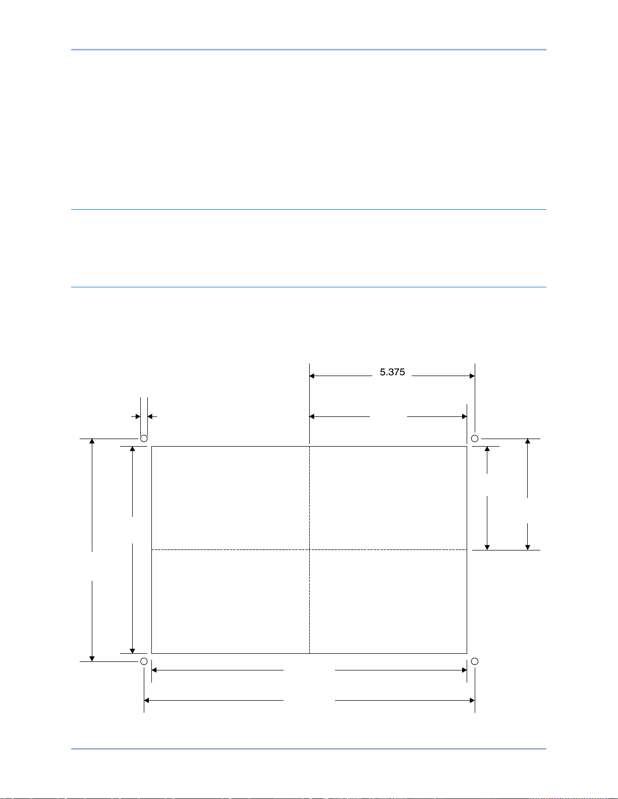
9469300990 Rev B 15
10.38
(263.7)
10.75
(273.1)
6
.
8
8
(
1
7
4.8
)
7
.
25
(
1
8
4
.
2
)
C
L
3.
4
4
(
8
7
.
4
)
3.
62
5
(
9
2
.
1
)
(
1
3
6
.
5
)
5.
19
(
1
3
1
.
8
)
P0071-79
0.
25
(
6
.
4
)
Mounting
DGC-2020HD controllers are delivered in sturdy cartons to prevent shipping damage. Upon receipt of a
unit, check the part number against the requisition and packing list for agreement. Inspect for damage,
and if there is evidence of such, immediately file a claim with the carrier and notify the Basler Electric
regional sales office or your sales representative.
If the device is not installed immediately, store it in the original shipping package in a moisture- and dustfree environment.
Hardware
The front panel is resistant to moisture, salt fog, humidity, dust, dirt, and chemical contaminants. DGC2020HD controllers are mounted using the four permanently attached 10-24 studs. The torque applied to
the mounting hardware should not exceed 20 inch-pounds (2.2 newton meters).
Dimensions
Panel cutting and drilling dimensions are shown in Figure 2. The horizontal drilling measurement of 10.75
inches has a tolerance of +0.01/–0.01 inches. The horizontal cutout measurement of 10.38 inches has a
tolerance of +0.04/–0 inches. The vertical drilling measurement of 7.25 inches has a tolerance of +0.01/–
0.01 inches. The vertical cutout measurement of 6.88 inches has a tolerance of +0.04/–0 inches. Overall
dimensions are shown in Figure 3. All dimensions are s hown in inches with mi llim eter s in pare nthesis.
DGC-2020HD Mounting
Figure 2. Panel Cutting and Drilling Dimensions
Page 26
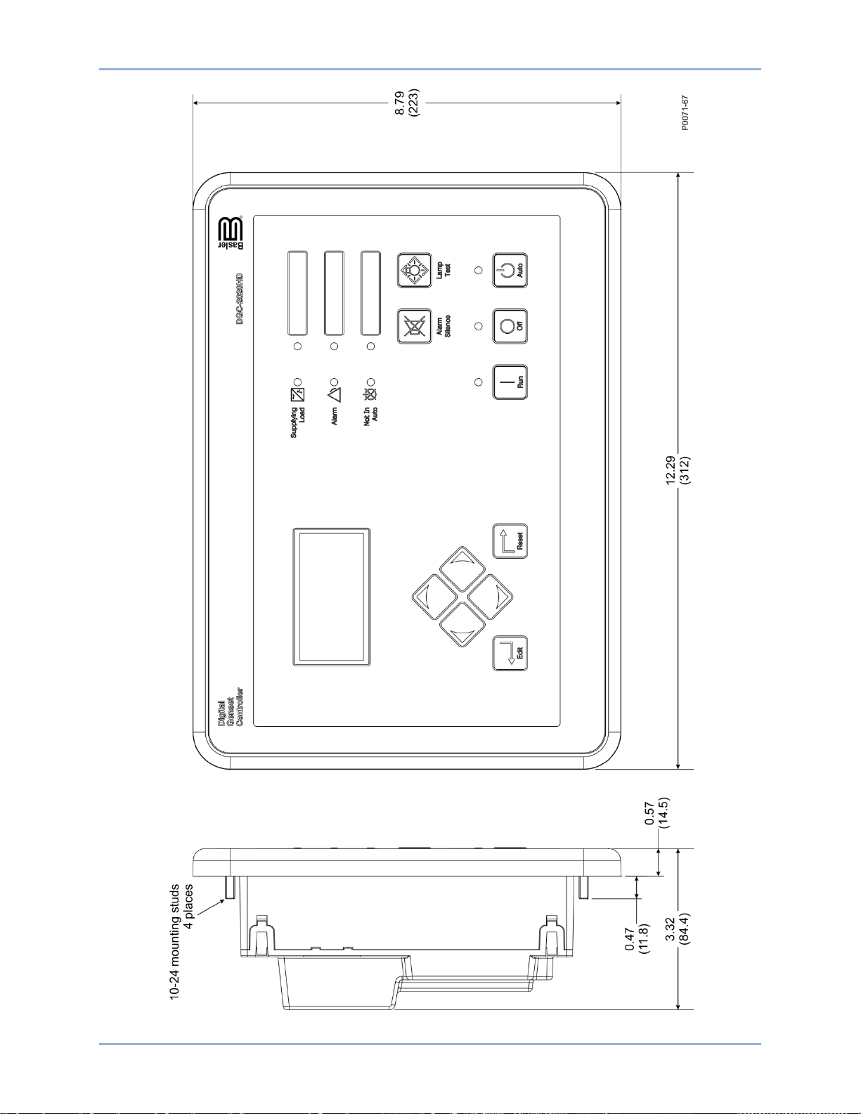
16 9469300990 Rev B
Figure 3. Overall Dimensions
Mounting DGC-2020HD
Page 27
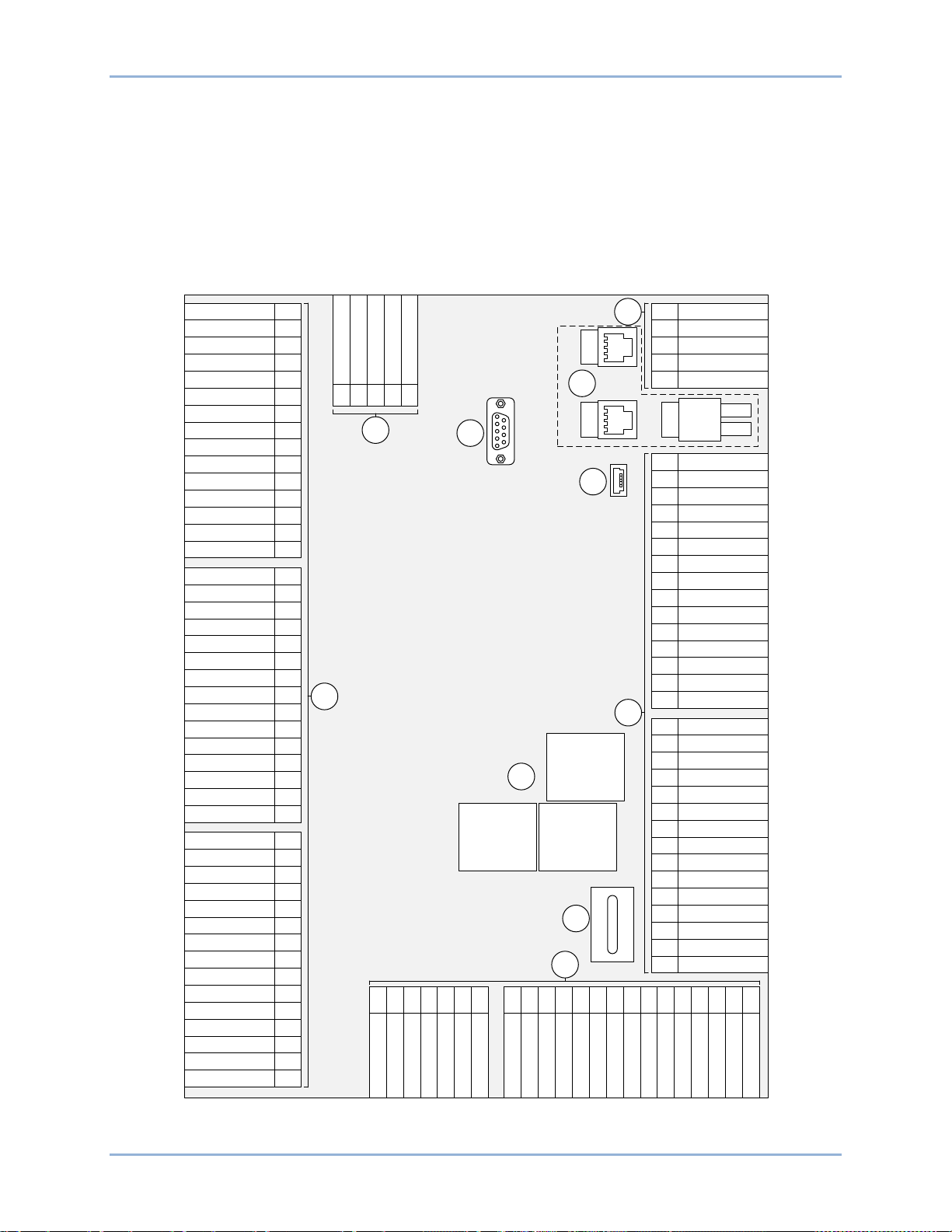
CAN
1
LOW
CAN 1 HIGH
SHIELD
CAN 2 LOW
CAN 2 HIGH
51
52
53
54
55
RS-485A
RS-485B
RS-485 SHIELD
IRIG-B+
IRIG-B−
RDP-110 TxD+
RDP-110 TxD−
CHASSIS GND
AVR +
AVR −
GOV +
GOV −
GOV PWM
LOAD SHARE+
LOAD SHARE−
Eth 1
57
58
59
60
61
62
63
64
65
66
67
68
69
70
FUEL +
FUEL −
Not Used
OIL +
OIL −
OIL I
COOLANT+
COOLANT−
COOLANT I
ALOG IN 2 +
ALOG IN 2 −
ALOG IN 2 I
ALOG IN 1 +
ALOG IN 1 −
ALOG IN 1 I
71
72
73
74
75
76
77
78
79
80
81
82
83
84
85
OUT 1
AUX I4−
AUX I4+
AUX I3−
AUX I3+
AUX I2−
AUX I2+
AUX I1−
AUX I1+
GEN IC−
GEN IC+
GEN IB−
GEN IB+
GEN IA−
GEN IA+
15
14
13
12
11
10
9
8
7
6
5
4
3
2
1
OUT 12
OUT 11
OUT 10
COM 7, 8, 9
OUT 9
OUT 8
OUT 7
COM 4, 5, 6
OUT 6
OUT 5
OUT 4
COM 1, 2, 3
OUT 3
OUT 2
30
29
28
27
26
25
24
23
22
21
20
19
18
17
16
P0071-12
CHASSIS GND
BATT −
BATT +
Not Used
INPUT 16
5049484746
INPUT 14
INPUT 13
INPUT 12
INPUT 11
INPUT 10
INPUT 9
INPUT 8
INPUT 7
INPUT 6
INPUT 5
INPUT 4
INPUT 3
INPUT 2
INPUT 1
45
44
43
42
41
40
39
38
37
36
35
34
33
32
31
BUS 2 VC
BUS 2 VN
Not Used
MPU +
MPU −
BUS 2 VB
Not Used
BUS 2 VA
Not Used
BUS 1 VN
BUS 1 VC
Not Used
BUS 1 VB
Not Used
BUS 1 VA
Not Used
GEN VN
GEN VC
Not Used
GEN VB
Not Used
GEN VA 86
87
88
89
90
91
92
93
94
95
96
97
98
99
100
101
102
103
104
105
106
107
COM 10, 11, 12
INPUT 15
RUN
START
PRE
DGC-2020HD
+
–
C
D
B
E
F
A
A
A
A
A
Tx
Rx
P1
P2
P3
P4
P5
P6
P7
P8P9
Eth 1
Eth 2
56
9469300990 Rev B 17
Terminals and Connectors
All DGC-2020HD terminals and connectors are located on the rear panel. DGC-2020HD terminals consist
of a mini-B USB jack, a DB-9 connector, Ethernet ports, plug-in connectors with spring clamp terminals,
and quarter-inch, male, quick-connect terminals.
Figure 4 illustrates the rear panel terminals. Locator letters in the illustration correspond to the terminal
block and connector descriptions in Table 1.
DGC-2020HD Terminals and Connectors
Figure 4. Rear Panel
Page 28

18 9469300990 Rev B
Locator
Description
A
The majority of external, DGC-2020HD wiring is terminated at 5-, 7-, or 15-position
wire size of 12 AWG (3.31 mm2).
B
This male DB-9 connector is provided for external dial-out modem communication and
protocol availability.
C
DGC-2020HD Ethernet communication uses the Modbus™ TCP protocol to provide
D
The mini-B USB jack mates with a standard USB cable and is used with a PC running
BESTCOMSPlus® software for local communication with the DGC-2020HD.
E
Connections to the Start, Run, and Pre output contacts are made directly to each relay
through quarter-inch, male, quick-connect term ina ls.
F
An onboard battery maintains DGC-2020HD timekeeping during losses of operating
to replace the battery with Basler Electric P/N 38526 may void the warranty.
Note
Table 1. Rear Panel Terminal and Connector Descriptions
connectors with spring clamp terminals. These connectors plug into headers on the
DGC-2020HD. The connectors and headers have a dovetailed edge that ensures
proper connector orientation. Each connector and header is uniquely keyed to ensure
that a connector mates only with the correct header. Terminals accept a maximum
the future implementation of other communication protocols. Contact Basler Electric for
remote metering, annunciation, and control. Dual copper (100Base-T) ports (style
xxxxDxxxx) use standard RJ-45 jacks while a fiber optic (100Base-F) port (style
xxxxFxxxx) uses two BNC fiber optic connectors.
Ethernet ports have different designations depending on style:
Dual copper (Style xxxxDxxxx) – The RJ-45 jack nearest to the mini-B USB port is
designated as Ethernet port 1 and is reserved for intergenset communications (load
sharing). The other RJ-45 jack is designated as Ethernet port 2 and can be configured
for redundant intergenset communications or for an independent network connection.
Fiber optic (Style xxxxFxxxx) – The fiber optic port is designated as Ethernet port 1
and is reserved for intergenset communications (load sharing).
Figure 4 shows both Ethernet port styles (dual copper and fiber) for clarity. The DGC2020HD comes equipped with only one port style, not both.
power. See the Timekeeping chapter, for instructions on replacing the battery. Failure
Terminals
DGC-2020HD connections are dependent on the application. Incorrect wiring may result in damage to the
controller.
Be sure that the DGC-2020HD is hard-wired to earth ground with no
smaller than 12 AWG (3.31 mm
ground (terminal 50) on the rear of the controller.
Operating power from the battery must be of the correct polarity. While
reverse polarity will not cause damage, the DGC-2020HD will not
operate.
2
) copper wire attached to chassis
The DGC-2020HD terminals are grouped by function and include operating power, current sensing,
voltage sensing, engine sender input, magnetic pickup input, contact sensing, output contacts, CAN
interface, RS-485 interface, AVR control, GOV control, Load Share, IRIG source, Remote Display Panel
connection, USB port, Ethernet communication, and RS-232 communication.
DGC-2020HD terminals are described in the following paragraphs.
Terminals and Connectors DGC-2020HD
Page 29

9469300990 Rev B 19
Terminal
Description
50 (CHASSIS)
Chassis ground connections
49 (BATT–)
Negative side of operating power input
48 (BATT+)
Positive side of operating power input
Terminals
Description
1 (IA+)
2 (IA–)
3 (IB+)
4 (IB–)
5 (IC+)
6 (IC–)
Terminal
Description
7 (AUX I1 +)
8 (AUX I1 –)
9 (AUX I2 +)
10 (AUX I2 –)
11 (AUX I3 +)
12 (AUX I3 –)
13 (AUX I4 +)
14 (AUX I4 –)
Operating Power
The DGC-2020HD operating power input accepts a nominal voltage of 12 Vdc or 24 Vdc and tolerates
voltage over the range of 6 to 32 Vdc. Operating power must be of the correct polarity. While reverse
polarity will not cause damage, the DGC-2020HD will not operate. Operating power terminals are listed in
Table 2.
A fuse should be added for additional protection for the wiring to the battery input of the DGC-2020HD. A
fuse helps prevent wire damage and nuisance trips due to initial power supply inrush current. To follow
UL guidelines, a 5 A maximum, 32 Vdc supplementary fuse must be implemented in the battery input
circuit to the DGC-2020HD.
Table 2. Operating Power Terminals
Generator Current Sensing
The DGC-2020HD has sensing inputs for A-phase, B-phase, and C-phase generator current. A DGC2020HD with a style number of 1xxxxxxxxx has 1 Aac nominal current sensing and a DGC-2020HD with a
style number of 5xxxxxxxx indicates 5 Aac nominal current sensing. Generator current sensing terminals
are listed in Table 3.
Table 3. Generator Current Sensing Terminals
A-phase current sensing input
B-phase current sensing input
C-phase current sensing input
Programmable Current Sensing
Four user-programmable current sensing inputs are provided for measuring mains current, load bus
current, ground current, or a combination of these. Table 4 lists the programmable current sensing
terminals.
Table 4. Programmable Current Sensing Terminals
Programmable current sensing input 1
Programmable current sensing input 2
Programmable current sensing input 3
DGC-2020HD Terminals and Connectors
Programmable current sensing input 4
Page 30

20 9469300990 Rev B
Caution
Note
Terminal
Description
86 (GEN VA)
A-phase generator voltage sensing input
88 (GEN VB)
B-phase generator voltage sensing input
90 (GEN VC)
C-phase generator voltage sensing input
91 (GEN VN)
Neutral generator voltage sensing input
Terminal
Description
93 (BUS1 VA)
A-phase bus voltage sensing input
95 (BUS1 VB)
B-phase bus voltage sensing input
97 (BUS1 VC)
C-phase bus voltage sensing input
98 (BUS1 VN)
Neutral bus voltage sensing input
100 (BUS2 VA)
A-phase bus voltage sensing input (optional)
101 (BUS2 VB)
B-phase bus voltage sensing input (optional)
103 (BUS2 VC)
C-phase bus voltage sensing input (optional)
104 (BUS2 VN)
Neutral bus voltage sensing input (optional)
Current sensing terminals 2 (IA–), 4 (IB–), 6 (IC–), 8(AUX I1–), 10
(AUX I2–), 12 (AUX I3–), and 14 (AUX I4–) mus t be te r mina ted to
ground for proper operation.
Unused current sensing inputs should be shorted to minimize noise
pickup.
Generator Voltage Sensing
The DGC-2020HD accepts either line-to-line or line-to-neutral generator sensing voltage over the range of
0 to 576 volts, rms line-to-line or 0 to 333 volts, rms line-to-neutral. Generator voltage sensing terminals
are listed in Table 5.
Table 5. Generator Voltage Sensing Terminals
Bus Voltage Sensing
Sensing of bus voltage enables the DGC-2020HD to detect failures of the mains (utility). Controllers with
style number xxx2xxxxx use bus voltage sensing to perform automatic synchronization of the generator
with the bus. The DGC-2020HD accepts either line-to-line or line-to-neutral bus sensing voltage over the
range of 0 to 576 volts, rms line-to-line or 0 to 333 volts, rms line-to-neutral. Controllers with style number
xxxxxxxEx are equipped with two bus sensing inputs. One is intended for sensing the mains voltage while
the other is intended for sensing the load bus voltage.
Bus voltage sensing terminals are listed in Table 6.
Table 6. Bus Voltage Sensing Terminals
Engine Sender Inputs
Inputs are provided for fuel level, oil pressure, and coolant temperature senders. For a listing of fuel level,
oil pressure, and coolant temperature senders that are compatible with the DGC-2020HD, refer to the
Terminals and Connectors DGC-2020HD
Page 31

9469300990 Rev B 21
Terminal
Description
71 (FUEL +)
Fuel level sender input
72 (FUEL –)
Fuel level sender return
74 (OIL + / ANALOG IN 4 +)
Oil pressure sender input or Analog input 4 +
75 (OIL – / ANALOG IN 4 –)
Oil pressure sender return or Analog input 4 –
76 (N.C. / ANALOG IN 4 I)
Analog input 4 (I) cur rent input ∗
77 (COOLANT + / ANALOG IN 3 +)
Coolant temperature sender input or Analog in put 3 +
78 (COOLANT – / ANALOG IN 3 –)
Coolant temperature sender return or Analog input 3 –
79 (N.C. / ANALOG IN 3 I)
Analog input 3 (I) cur rent in put ∗
Terminal
Description
80 (ANALOG IN 1 +)
Auxiliary ana log 1 +
81 (ANALOG IN 1 –)
Auxiliary ana log 1 –
82 (ANALOG IN 1 I)
Auxiliary ana log 1 (I) current input∗
83 (ANALOG IN 2 +)
Auxiliary ana log 2 +
84 (ANALOG IN 2 –)
Auxiliary ana log 2 –
85 (ANALOG IN 2 I)
Auxiliary analog 2 (I) current input∗
Terminals
Description
105 (MPU–)
Magnetic pickup return input
106 (MPU+)
Magnetic pickup positive input
Engine Sender Inputs chapter. The fuel level input accepts resistive senders only. Oil pressure and
coolant temperature inputs accept either resistive or analog senders depending on the style number.
Engine sender input terminals are listed in Table 7.
Table 7. Sender Input Terminals
∗When using the current input, it must be tied to the voltage input. See the Typical Applications
chapter for a diagram.
Analog Inputs
Two user-programmable analog inputs are provided. These inputs accept a signal range of either 4 to
20 mA or 0 to 10 Vdc. Analog input terminals are listed in Table 8.
Table 8. Analog Input Terminals
∗When using the current input, it must be tied to the voltage input. See Typical
Applications chapter for a diagram.
Magnetic Pickup Input
The magnetic pickup input accepts a speed signal over the range of 3 to 35 volts peak and 32 to 10,000
hertz. Magnetic pickup input terminals are listed in Table 9.
Table 9. Magnetic Pickup Input Terminals
Contact Sensing Inputs
Contact sensing inputs consist of sixteen programmable inputs. The programmable inputs accept
normally open, dry contacts. Terminal 49 (BATT–) serves as the common return line for the
programmable inputs. While input 1 is programmed to recogniz e an emergency stop input by default, it
can be programmed for any function. Information about configuring the programmable inputs is provided
in the Contact Inputs chapter. Contact sensing input terminals are listed in Table 10.
DGC-2020HD Terminals and Connectors
Page 32

22 9469300990 Rev B
Terminal
Description
49 (BATT–)
Common return line for programmable contact inputs
31 (INPUT 1)
Programmable contact input 1
32 (INPUT 2)
Programmable contact input 2
33 (INPUT 3)
Programmable contact input 3
34 (INPUT 4)
Programmable contact input 4
35 (INPUT 5)
Programmable contact input 5
36 (INPUT 6)
Programmable contact input 6
37 (INPUT 7)
Programmable contact input 7
38 (INPUT 8)
Programmable contact input 8
39 (INPUT 9)
Programmable contact input 9
40 (INPUT 10)
Programmable contact input 10
41 (INPUT 11)
Programmable contact input 11
42 (INPUT 12)
Programmable contact input 12
43 (INPUT 13)
Programmable contact input 13
44 (INPUT 14)
Programmable contact input 14
45 (INPUT 15)
Programmable contact input 15
46 (INPUT 16)
Programmable contact input 16
Terminal
Description
19 (START)
Start output contact (Start solenoid)
20 (START)
21 (RUN)
Run output contact (Fuel solenoid)
22 (RUN)
23 (PRE)
Pre-start output contact (Glow plugs)
24 (PRE)
Terminal
Description
15 (OUT 1)
Programmable output 1
16 (OUT 2)
Programmable output 2
17 (OUT 3)
Programmable output 3
18 (COM 1, 2, 3)
Common connection for outputs 1, 2, and 3
19 (OUT 4)
Programmable output 4
Table 10. Contact Sensing Inputs
Output Contacts
The DGC-2020HD has three sets of fixed-function output contacts: Pre, Start, and Run. The Pre contacts
supply battery power to the engine glow plugs, the Start contacts supply power to the starter solenoid,
and the Run contacts supply power to the fuel solenoid. Connections to the three sets of contacts are
made at terminals 19 through 24. The Pre, Start, and Run relay terminals are listed in Table 11.
Table 11. Fixed-Function Output Contact Terminals
Twelve programmable output contacts are provided in four sets. Each set of three output contacts shares
a common terminal. Programmable output contact terminals are listed in Table 12.
Table 12. Programmable Output Contact Terminals
Terminals and Connectors DGC-2020HD
Page 33

9469300990 Rev B 23
Terminal
Description
20 (OUT 5)
Programmable output 5
21 (OUT 6)
Programmable output 6
22 (COM 4, 5, 6)
Common connection for outputs 4, 5, and 6
23 (OUT 7)
Programmable output 7
24 (OUT 8)
Programmable output 8
25 (OUT 9)
Programmable output 9
26 (COM 7, 8, 9)
Common connection for outputs 7, 8, and 9
27 (OUT 10)
Programmable output 10
28 (OUT 11)
Programmable output 11
29 (OUT 12)
Programmable output 12
30 (COM 10, 11, 12)
Common connection for outputs 10, 11, and 12
Terminals
Description
51 (CAN 1 L)
CAN 1 low connection
52 (CAN 1 H)
CAN 1 high connection
53 (SHIELD)
CAN drain connection
54 (CAN 2 L)
CAN 2 low connection
55 (CAN 2 H)
CAN 2 high connection
Note
CAN Interface
These terminals provide communication using the SAE J1939 protocol or the MTU protocol and provide
high-speed communication between the DGC-2020HD and an ECU on an electronically controlled
engine. Connections between the ECU and DGC-2020HD should be made with twisted-pair, shielded
cable. CAN interface terminals are listed in Table 13. For typical CAN connections, refer to the Typical
Connections chapter.
Table 13. CAN Interface Terminals
1. If the DGC-2020HD is providing one end of the J1939 bus, a
120 Ω, ½ watt terminating resistor should be installed across
terminals 51 (CAN1L) and 52 (CAN1H) or 54 (CAN2L) and 55
(CAN2H)
2. If the DGC-2020HD is not providing one end of the J1939 bus, the
stub connecting the DGC-2020HD to the bus should not exceed
914 mm (3 ft) in length.
3. The maximum bus length, not including stubs, is 40 m (131 ft).
4. The J1939 drain (shield) should be grounded at one point only. If
grounded elsewhere, do not connect the dr ai n to the DGC2020HD.
RS-485 Interface
DGC-2020HD controllers can be monitored and controlled via a polled network using the Modbus™
protocol. The RS-485 por t suppor ts a user-selectable baud rate of 1,200, 2,400, 4,800, 9,600, 19,200,
38,400, 57,600, or 115,200. Seven or eight data bits per character can be selected. Odd, even, or no
DGC-2020HD Terminals and Connectors
Page 34

24 9469300990 Rev B
Terminal
Description
56 (RS-485 A)
RS-485 send/receive A connection
57 (RS-485 B)
RS-485 send/receive B connection
58 (RS-485 SHIELD)
RS-485 shield connection
Terminal
Description
64 (AVR +)
AVR control output positive
65 (AVR –)
AVR control output negative
Terminal
Description
66 (GOV +)
GOV control output positive
67 (GOV –)
GOV control output negative
68 (GOV PWM)
GOV PWM output for CAT control system interface
Terminal
Description
69 (LOAD SHARE +)
Load share line positive
70 (LOAD SHARE –)
Load share line negative
Terminal
Description
59 (IRIG-B +)
IRIG-B source input
60 (IRIG-B –)
IRIG-B return terminal
parity is supported. One or two stop bits are selectable. Modbus register values for the DGC-2020HD are
listed and defined in Basler Publication 9469300991, Instruction Manual for DGC-2020HD Digital Genset
Controller Modbus™ Protoc ol. RS-485 interface terminals are listed in Table 14.
Table 14. RS-485 Terminals
Automatic Voltage Regulator (AVR) Control
AVR control outputs provide control of the generator voltage setpoint. AVR control terminals are listed in
Table 15.
Table 15. AVR Control Output Terminals
Governor (GOV) Control
GOV control output contacts provide remote control of the generator speed (RPM) setpoint. GOV control
terminals are listed in Table 16.
Table 16. GOV Control Output Terminals
Load Share Line
Load share line outputs are measured and used to calculate the per-unitized average load level. This
average is used as the setpoint for the genset’s kW controller. Load share line output terminals are listed
in Table 17.
Table 17. Load Share Line Output Terminals
IRIG-B Connections
The IRIG-B terminals connect to an IRIG-B source for synchronization of DGC-2020HD timekeeping with
the IRIG-B source. Table 18 lists the IRIG-B source input terminals.
Table 18. IRIG-B Source Input Terminals
Terminals and Connectors DGC-2020HD
Page 35

9469300990 Rev B 25
Terminal
Description
61 (RDP TxD +)
Remote display panel communication terminal (TxD +)
62 (RDP TxD –)
Remote display panel communication terminal (TxD –)
49 (BATT–)
Remote display panel power terminal DC COM (–)
48 (BATT+)
Remote display panel power terminal 12/24 (+)
Optional Remote Display Panel Connections
Terminals are provided for connection with the optional remote display panel (Basler P/N 9318100114
projection mount or 9318100115 flush mount). These terminals provide dc operating power to the remote
display panel and enable communication between the DGC-2020HD and the remote display panel.
Twisted-pair conductors are recommended for making the connections between the DGC-2020HD and
remote display panel. Communication may become unreliable if the connection wires exceed 1,219 m
(4,000 ft). Table 19 lists the DGC-2020HD terminals that connect to the remote display panel.
Table 19. Remote Display Panel Interface Terminals
Connectors
USB Interface
A mini-B USB jack enables local commun ic ati on with a PC runni ng BE STCO M SPlus® software. The
DGC-2020HD is connected to a PC using a standard USB cable equipped with a type A plug on one end
(PC termination) and a mini-B plug on the other end (DGC-2020HD termination).
Ethernet Communications
Dual copper RJ-45 jacks or a BNC fiber optic port provide Ethernet communications between the DGC2020HD and a PC via BESTCOMSPlus or other DGC-2020HDs in a network. An Ethernet connection to a
PC running BESTCOMSPlus provides remote metering, setting, annunciation, and control of the DGC2020HD. Ethernet communication between DGC-2020HDs allows for generator sequencing on an
islanded system.
RS-232 Interface
A male DB-9 connector allows the DGC-2020HD controller to connect to an external, user-supplied dialout modem via the RS-232 interface. The modem enables the DGC-2020HD to dial up to four pager
telephone numbers and annunciate conditions selected by the user. These conditions include any DGC2020HD alarm or pre-alarm, closure of any programmable contact input, and an active cool down timer.
DGC-2020HD Terminals and Connectors
Page 36

26 9469300990 Rev B
Terminals and Connectors DGC-2020HD
Page 37

9469300990 Rev B 27
Typical Applications
Typical connection diagrams are provided in this chapter as a guide when wiring the DGC-2020HD for
communication, mechanical senders, contact inputs and outputs, sensing, and operating power.
Connections for Typical Applications
Typical connections for applications which use three-phase wye, three-phase delta, single-phase A-B,
and single-phase A-C generator voltage sensing are shown on the following pages.
Figure 5 illustrates typical three-phase wye generator voltage sensing connections.
DGC-2020HD Typical Applic a tions
Page 38

28 9469300990 Rev B
106
107
MPU+
MPU–
1
IA–
2
IA+
3
IB–
4
IB+
5
IC–
6
IC+
A
B
C
N
30
15
OUT 1
16
17
18
19
20
21
22
23
24
25
26
27
28
29
OUT 2
OUT 3
OUT 4
OUT 5
OUT 6
OUT 7
OUT 8
OUT 9
OUT
10
OUT 11
OUT 12
PRE
RUN
START
START
SOLENOID
FUEL
SOLENOID
49
BATT–48BATT+
50
CHASSIS
GLOW PLUGS
71
FUEL +
46
45
INPUT
16
44
43
42
41
40
39
38
37
36
35
34
33
32
31
INPUT 15
INPUT 14
INPUT 13
INPUT 12
INPUT 11
INPUT 10
INPUT 8
INPUT 9
INPUT 7
INPUT 6
INPUT 5
INPUT 3
INPUT 4
INPUT 2
INPUT
1
61 62
Horn
Not in Auto
Global Alarm
Global Pre-
Alarm
Open Generator Breaker
Close Generator Breaker
Open Mains Breaker
Close Mains Breaker
Governor Raise
Emergency Stop
Mains Bkr Status
Gen Bkr Status
Close Mains Breaker
Open Mains Breaker
Close Gen Breaker
Open Gen Breaker
P0071-25
M
P
U
L1
L
2
L3
N
12/24V
RDP-110 TXD+
RDP-110 TXD–
Mini-B
USB
RS-232
DB-9
57
485B
56
485A58485 SHIELD
52
CAN 1 H53SHIELD
51
CAN 1 L
DGC-2020HD
1
Labels indicate the functions assigned by the default programmable
logic to the contact inputs and output contacts.
2
Current inputs are
1A or 5A,
depending on style.
3
4
5
LOAD
55
CAN 2 H54CAN 2 L
72
FUEL –
74
ANALOG IN 4 + / OIL +
75
ANALOG IN 4 – / OIL –
76
ANALOG IN 4 I /
N.C
.
77
ANALOG IN 3 + / COOLANT +
78
ANALOG IN 3 –
/ COOLANT –
79
ANALOG IN
3 I /
N.C
.
59 60
IRIG-B +
IRIG-B –
7
AUX I1–
8
AUX I1+
9
AUX I2–
10
AUX I2+
11
AUX I3–
12
AUX I3+
13
AUX I4–
14
AUX I4+
80
ANALOG IN 2 +
81
ANALOG IN 2 –
82
ANALOG IN 2 I
83
ANALOG IN 1 +
84
ANALOG IN 1 –
85
ANALOG IN 1 I
GENERATOR
≤ 480 V
MAINS CKT
BKR
GEN CKT
BKR
86
GEN VA88GEN VB
90
GEN VC91GEN VN
BUS1 VB
97
BUS1 VC
BUS
1 VA
93 95 98
BUS1 VN
BUS2 VB
103
BUS2 VC
BUS2 VA
100 101 104
BUS2 VN
Terminals 74 through 79 support analog inputs or resistive senders
,
depending on style (resistive senders shown).
64
65
66
67
68
69
70
AVR +
AVR –
GOV +
GOV –
GOV PWM
LOAD SHARE +
LOAD SHARE –
1 1 1 1 1
1 1
4
4
To CAN 1
To CAN 2
To ECU Power or
Key-on Terminal
Connect to the ECU on an electronically controlled engine.
If component is under ECU control, do not connect to DGC-
2020HD.
6
6
7
7
7
6
Connect to CAN
1 (
AEM-2020
/ CEM-2020 network) only.
8
2
Fiber Optic
Ethernet
Base-100F
Copper
Ethernet
Base-100T
Copper
Ethernet
Base-100T
OR
7
For optimal metering performance, it is recommended to connect
analog input common to BATT
–
(49).
3
3
3
3
0 to 10 V or
4 to 20 mA
source
0 to 10 V or
4 to 20 mA
source
8
5
5
5
5
When using analog current inputs, the ‘+’ and ‘I’ terminals must be
tied.
Figure 5. 3-Phase Wye Connections for Typical Applications
Typical Applic a tions DGC-2020HD
Page 39

9469300990 Rev B 29
106
107
MPU+
MPU–
1
IA–
2
IA+
3
IB–
4
IB+
5
IC–
6
IC+
A
B
C
N
30
15
OUT 1
16
17
18
19
20
21
22
23
24
25
26
27
28
29
OUT 2
OUT 3
OUT 4
OUT
5
OUT 6
OUT
7
OUT 8
OUT 9
OUT 10
OUT 11
OUT 12
PRE
RUN
START
START
SOLENOID
FUEL
SOLENOID
49
BATT–48BATT
+
50
CHASSIS
GLOW PLUGS
71
FUEL +
46
45
INPUT 16
44
43
42
41
40
39
38
37
36
35
34
33
32
31
INPUT 15
INPUT 14
INPUT 13
INPUT 12
INPUT 11
INPUT 10
INPUT 8
INPUT 9
INPUT 7
INPUT
6
INPUT 5
INPUT 3
INPUT 4
INPUT 2
INPUT 1
61 62
Horn
Not in Auto
Global Alarm
Global Pre-Alarm
Open Generator Breaker
Close Generator Breaker
Open Mains Breaker
Close Mains Breaker
Governor Raise
Emergency Stop
Mains Bkr Status
Gen Bkr Status
Close Mains Breaker
Open Mains Breaker
Close Gen Breaker
Open Gen Breaker
P0071-55
M
P
U
L1
L2
L3
N
12/24V
RDP-110 TXD+
RDP-110 TXD–
Mini-B
USB
RS-232
DB-9
57
485B56485A58485 SHIELD
52
CAN 1 H53SHIELD
51
CAN 1 L
DGC-2020
HD
1
Labels indicate the functions assigned by the default programmable
logic to the contact inputs and output contacts.
2
Current inputs are 1A or 5A, depending on style.
3
4
5
LOAD
55
CAN 2 H54CAN 2 L
72
FUEL –
74
ANALOG IN
4 + / OIL
+
75
ANALOG IN 4
– / OIL
–
76
ANALOG IN 4 I / N.C.
77
ANALOG IN 3 + / COOLANT +
78
ANALOG IN 3 – / COOLANT –
79
ANALOG IN 3 I / N.C.
59 60
IRIG-B +
IRIG-B –
7
AUX I1–
8
AUX I1+
9
AUX I2–
10
AUX I2+
11
AUX I3–
12
AUX I3+
13
AUX I4–
14
AUX I4+
80
ANALOG IN 2 +
81
ANALOG IN 2
–
82
ANALOG IN 2 I
83
ANALOG IN
1 +
84
ANALOG IN 1 –
85
ANALOG IN 1 I
GENERATOR
≤ 480 V
MAINS CKT
BKR
GEN CKT
BKR
86
GEN VA88GEN VB
90
GEN VC91GEN VN
BUS1 VB
97
BUS
1 VC
BUS1
VA
93 95 98
BUS1 VN
BUS2 VB
103
BUS
2 VC
BUS2 VA
100 101 104
BUS2 VN
Terminals 74 through
79 support analog inputs or resistive senders,
depending on style (resistive senders shown).
64
65
66
67
68
69
70
AVR +
AVR –
GOV +
GOV –
GOV PWM
LOAD SHARE
+
LOAD SHARE
–
1
1
1 1 1 1 1
4
4
To CAN 1
To CAN 2
To ECU Power or
Key-on Terminal
Connect to the ECU on an electronically controlled engine.
If component is under ECU control,
do not connect to DGC-2020HD.
6
6
7
7
7
6
Connect to CAN 1 (AEM
-2020 / CEM-2020 network) only.
8
2
Fiber Optic
Ethernet
Base-100F
Copper
Ethernet
Base-
100T
Copper
Ethernet
Base-100
T
OR
7
For optimal metering performance
, it is recommended to connect
analog input common to BATT– (49).
3
3
3
3
0
to 10 V or
4 to 20 mA
source
0 to 10
V or
4
to 20 mA
source
8
5
5
5
5
When using analog current inputs, the ‘+’ and ‘I’ terminals must be
tied.
Figure 6 illustrates typical three-phase delta generator voltage sensing connections.
Figure 6. 3-Phase Delta Connections for Typical Applications
DGC-2020HD Typical Applic a tions
Page 40

30 9469300990 Rev B
106
107
MPU+
MPU–
1
IA–
2
IA+
3
IB–
4
IB+
5
IC–
6
IC+
A
B
N
30
15
OUT 1
16
17
18
19
20
21
22
23
24
25
26
27
28
29
OUT 2
OUT 3
OUT 4
OUT
5
OUT 6
OUT
7
OUT 8
OUT 9
OUT 10
OUT 11
OUT 12
PRE
RUN
START
START
SOLENOID
FUEL
SOLENOID
49
BATT–48BATT+
50
CHASSIS
GLOW PLUGS
71
FUEL +
46
45
INPUT 16
44
43
42
41
40
39
38
37
36
35
34
33
32
31
INPUT 15
INPUT 14
INPUT 13
INPUT 12
INPUT 11
INPUT 10
INPUT 8
INPUT 9
INPUT 7
INPUT
6
INPUT 5
INPUT 3
INPUT 4
INPUT 2
INPUT 1
61 62
Horn
Not in Auto
Global Alarm
Global Pre-Alarm
Open Generator Breaker
Close Generator Breaker
Open Mains Breaker
Close Mains Breaker
Governor Raise
Emergency Stop
Mains Bkr Status
Gen Bkr Status
Close Mains Breaker
Open Mains Breaker
Close Gen Breaker
Open Gen Breaker
P0071-56
M
P
U
L1
L2
N
12/24V
RDP-110 TXD+
RDP-110 TXD–
Mini-B
USB
RS-232
DB-9
57
485B56485A58485 SHIELD
52
CAN
1 H
53
SHIELD
51
CAN 1 L
DGC-2020
HD
1
Labels indicate the functions assigned by the default programmable
logic to the contact inputs and output contacts.
2
Current inputs are 1A or 5A, depending on style.
3
4
5
LOAD
55
CAN
2
H
54
CAN 2 L
72
FUEL –
74
ANALOG IN
4 + / OIL
+
75
ANALOG IN 4
– / OIL
–
76
ANALOG IN 4 I / N.C.
77
ANALOG IN 3 + / COOLANT +
78
ANALOG IN 3 – / COOLANT –
79
ANALOG IN 3 I / N.C.
59 60
IRIG-B +
IRIG-B –
7
AUX I1–
8
AUX I1+
9
AUX I2–
10
AUX I2+
11
AUX I3–
12
AUX I3+
13
AUX I4–
14
AUX I4+
80
ANALOG IN 2 +
81
ANALOG IN 2
–
82
ANALOG IN 2 I
83
ANALOG IN
1 +
84
ANALOG IN 1 –
85
ANALOG IN 1 I
GENERATOR
≤ 480 V
MAINS CKT
BKR
GEN CKT
BKR
86
GEN VA88GEN VB
90
GEN VC91GEN VN
BUS1 VB
97
BUS1 VC
BUS1 VA
93 95 98
BUS1 VN
BUS2 VB
103
BUS2 VC
BUS2 VA
100 101 104
BUS2 VN
Terminals 74 through
79 support analog inputs or resistive senders,
depending on style (resistive senders shown).
64
65
66
67
68
69
70
AVR +
AVR –
GOV +
GOV –
GOV PWM
LOAD SHARE
+
LOAD SHARE
–
1
1 1 1 1
4
4
To CAN 1
To CAN 2
To ECU Power or
Key-on Terminal
Connect to the ECU on an electronically controlled engine.
If component is under ECU control, do not connect to DGC-2020HD.
6
6
7
7
7
6
Connect to CAN 1 (AEM-
2020 / CEM-2020 network) only.
8
2
Fiber Optic
Ethernet
Base-100F
Copper
Ethernet
Base-100T
Copper
Ethernet
Base-100T
OR
7
For optimal metering performance,
it is recommended to connect
analog input common to BATT– (49).
3
3
3
3
0 to 10 V or
4 to 20 mA
source
0
to
10 V or
4 to 20
mA
source
8
5
5
5
5
When using analog current inputs, the ‘+’ and ‘I’ terminals must be
tied
.
Figure 7 illustrates typical single-phase A-B generator voltage sensing connections.
Figure 7. Single-Phase A-B Connections for Typical Applications
Typical Applic a tions DGC-2020HD
Page 41

9469300990 Rev B 31
106
107
MPU+
MPU–
1
IA–
2
IA+
3
IB–
4
IB+
5
IC–
6
IC+
A
C
N
30
15
OUT 1
16
17
18
19
20
21
22
23
24
25
26
27
28
29
OUT 2
OUT 3
OUT 4
OUT
5
OUT 6
OUT
7
OUT 8
OUT 9
OUT 10
OUT 11
OUT 12
PRE
RUN
START
START
SOLENOID
FUEL
SOLENOID
49
BATT–48BATT+
50
CHASSIS
GLOW PLUGS
71
FUEL +
46
45
INPUT 16
44
43
42
41
40
39
38
37
36
35
34
33
32
31
INPUT 15
INPUT 14
INPUT 13
INPUT 12
INPUT 11
INPUT 10
INPUT 8
INPUT 9
INPUT 7
INPUT
6
INPUT 5
INPUT 3
INPUT 4
INPUT 2
INPUT 1
61 62
Horn
Not in Auto
Global Alarm
Global Pre-Alarm
Open Generator Breaker
Close Generator Breaker
Open Mains Breaker
Close Mains Breaker
Governor Raise
Emergency Stop
Mains Bkr Status
Gen Bkr Status
Close Mains Breaker
Open Mains Breaker
Close Gen Breaker
Open Gen Breaker
P0071-57
M
P
U
L1
L3
N
12/24V
RDP-110 TXD+
RDP-110 TXD–
Mini-B
USB
RS-232
DB-9
57
485B56485A58485 SHIELD
52
CAN
1 H
53
SHIELD
51
CAN 1 L
DGC-2020
HD
1
Labels indicate the functions assigned by the default programmable
logic to the contact inputs and output contacts.
2
Current inputs are 1A or 5A, depending on style.
3
4
5
LOAD
55
CAN 2 H54CAN 2 L
72
FUEL
–
74
ANALOG IN 4
+ /
OIL +
75
ANALOG IN 4 –
/ OIL –
76
ANALOG IN 4 I / N.C.
77
ANALOG IN 3 + / COOLANT +
78
ANALOG IN 3 – / COOLANT –
79
ANALOG IN 3 I / N.
C.
59 60
IRIG-B +
IRIG-B –
7
AUX I1–
8
AUX I1+
9
AUX I2–
10
AUX I2+
11
AUX I3–
12
AUX I3+
13
AUX I4–
14
AUX I4+
80
ANALOG IN 2 +
81
ANALOG IN 2 –
82
ANALOG IN
2 I
83
ANALOG IN 1
+
84
ANALOG IN 1 –
85
ANALOG IN 1 I
GENERATOR
≤ 480 V
MAINS CKT
BKR
GEN CKT
BKR
86
GEN VA88GEN VB
90
GEN VC91GEN VN
BUS1 VB
97
BUS
1 VC
BUS1
VA
93 95 98
BUS1 VN
BUS2 VB
103
BUS
2 VC
BUS2 VA
100 101 104
BUS2 VN
Terminals 74 through 79
support analog inputs or resistive senders,
depending on style (resistive senders shown).
64
65
66
67
68
69
70
AVR +
AVR –
GOV +
GOV –
GOV PWM
LOAD SHARE +
LOAD SHARE –
1 1 1 1 1
5
5
To CAN 1
To CAN 2
To ECU Power or
Key-on Terminal
Connect to the ECU on an electronically controlled engine.
If component is under ECU control, do not connect to DGC-2020HD.
7
7
8
8
8
6
Connect to CAN 1 (AEM-2020 / CEM-
2020 network) only.
9
3
Fiber Optic
Ethernet
Base-100F
Copper
Ethernet
Base-100T
Copper
Ethernet
Base-100T
OR
7
For optimal metering performance, it is recommended to connect
analog input common to BATT– (49).
4
4
4
4
0
to 10 V or
4 to 20 mA
source
0 to 10
V or
4
to 20 mA
source
8
6
6
6
6
When using analog current inputs, the ‘+’ and ‘I’ terminals must be
tied.
2
9
Optional. Jumper terminals 88 and 90.
Figure 8 illustrates typical single-phase A-C generator voltage sensing connections.
Figure 8. Single-Phase A-C Connections for Typical Applications
DGC-2020HD Typical Applic a tions
Page 42

32 9469300990 Rev B
GEN
ENG
LOAD
64
65
66
67
Generator
Breaker
Breaker Control
Analog Load Share Line
69
70
Ethernet
AVR +
AVR –
GOV +
GOV –
LS +
LS –
DGC-2020HD
Industrial
Ethernet Switch
To Other
DGC-2020HDs
To Other
DGC-2020HDs
AVR
GOV
Generator Metering
Bus Metering
GEN
ENG
64
65
66
67
Generator
Breaker
Breaker Control
69
70
Ethernet
AVR +
AVR –
GOV +
GOV –
LS +
LS –
DGC-2020HD
AVR
GOV
Generator Metering
Bus Metering
Notes:
Up to 32 DGC-2020HDs are supported on one network.
1
1
Ethernet Load Share Line
P0071-68
Connections for Load Sharing
Figure 9 illustrates a typical interconnection of two systems tied together using analog and Ethernet load
share lines.
Figure 9. Analog and Ethernet Connections for Typical Applications
Typical Applic a tions DGC-2020HD
Page 43

9469300990 Rev B 33
Note
ALOG IN +
ALOG IN –
ALOG IN I
DGC-2020HD
P0071-65
4 – 20 mA
Current
Transducer
BATT –49
For optimal metering performance, it is recommended to
connect analog input common to terminal 49 (BATT –).
Note:
1
1
0 – 10 Vdc
Voltage
Transducer
ALOG IN +
ALOG IN –
ALOG IN I
DGC-2020HD
BATT –49
1
Analog Voltage Input Connection
Analog Current Input Connection
Analog Input Connections
DGC-2020HD controllers with style number xxxxxxxxR are equipped with two analog inputs and those
with style number xx x x xxx xA are equip ped wit h four analog inputs.
Voltage and current analog input connections are shown in Figure 10. When using the current input, the
“+” and “I” terminals must be tied together.
Figure 10. Analog Engine Sender Voltage Input Connections
CAN Connections
Typical CAN connections are shown in Figure 11 and Figure 12.
1. If the DGC-2020HD is providing one end of the J1939 bus, a 120 Ω, ½
watt terminating resistor should be installed across terminals 51 (CAN1L)
and 52 (CAN1H) or 54 (CAN2L) and 55 (CAN2H).
2. If the DGC-2020HD is not providing one end of the J1939 bus, the stub
connecting the DGC-2020HD to the bus should not exceed 914 mm (3 ft)
in length.
3. The maximum bus length, not including stubs, is 40 m (131 ft).
4. The J1939 drain (shield) should be grounded at one point only. If
grounded elsewhere, do not connect the dr ai n to the DGC-2020HD.
DGC-2020HD Typical Applic a tions
Page 44

34 9469300990 Rev B
DGC-2020HD
P0071-62
120 ohm
Termination
CAN-H
CAN-L
CEM-2020
(Optional,
up to 4)
120 ohm
Termination
CAN 2 Bus
Stub
AEM-2020
(Optional,
up to 4)
Other
Devices
Engine
120 ohm
Termination
CAN-H
CAN-L
120 ohm
Termination
CAN 1 Bus
Stub
CAN 2
CAN 1
DGC-2020HD
P0071-63
120 ohm
Termination
CAN-H
CAN-L
CEM-2020
(Optional,
up to 4)
120 ohm
Termination
CAN 2 Bus
Stub
AEM-2020
(Optional,
up to 4)
Other
Devices
Engine
120 ohm
Termination
CAN-H
CAN-L
120 ohm
Termination
CAN 1 Bus
Stub
Figure 11. CAN Interface with DGC-2020HD Providing One End of the Bus
Figure 12. CAN Interface with Other Devices Providing One End of the Bus.
Typical Applic a tions DGC-2020HD
Page 45

9469300990 Rev B 35
P0071
-52
DGC
-2020
HD
53
)
SHIELD
52)
CAN
1 H
51
)
CAN
1 L
AEM-
2020
(2
)
GND
CANH
CANL
CEM-
2020
(1
)
GND
CANH
CANL
CEM-
2020
(2
)
GND
CANH
CANL
CEM-2020
(3
)
GND
CANH
CANL
CEM
-2020 (
4)
GND
CANH
CANL
AEM
-
2020 (
1)
GND
CANH
CANL
AEM-
2020 (
3)
GND
CANH
CANL
AEM-
2020 (4
)
GND
CANH
CANL
1
The J1939 drain (
shield)
should be grounded at one
point only. If grounded elsewhere
, do not connect the
drain to the DGC
-2020HD.
1
Note:
Expansion Module Connections (CAN 1)
The AEM-2020 (Analog Expans i on Modu le) and CE M-2020 (Contact Expansion Module) are optional
modules that may be installed with the DGC-2020HD. These modules interface to the DGC-2020HD via
the “CAN 1” interface, thus the CAN terminals (51, 52, and 53) are the only common connections
between the DGC-2020HD, AEM-2020, and CEM-2020. Up to four CEM-2020 modules and up to four
AEM-2020 modules are supported on a network. Typical connections are illustrated in Figure 13.
Refer to the AEM-2020 and CEM-2020 chapters for more information.
Figure 13. DGC-2020HD Expansion Module CAN Connections
Installation for CE Syst ems
For CE compliant systems, it may be required to route ac voltage and current sensing wires separately
from other wires.
DGC-2020HD Typical Applic a tions
Page 46

36 9469300990 Rev B
Typical Applic a tions DGC-2020HD
Page 47

9469300990 Rev B 37
Controls and Indicators
DGC-2020HD controls and indicators are located on the front panel and are intended for local control and
monitoring of DGC-2020HD operation. Front panel controls consist of sealed membrane pushbuttons.
Front panel indicators consist of LED (light emitting diode) indicators and a backlit LCD (liquid crystal
display).
DGC-2020HD controls and ind icator s are illus tr at ed in Figure 14. Lettered locators in Figure 14
correspond to the control and indicator descriptions of Table 20.
Figure 14. Front Panel Controls and Indicators
DGC-2020HD Controls and Indicators
Page 48

38 9469300990 Rev B
Locator
Description
Liquid Crystal Display. The backlit, 64 by 128 pixel LCD serves as the local information
maintained down to –40°F (−40°C).
Not in Auto Indicator. This red LED lights when the DGC-2020HD is not operating in Auto
mode.
Alarm Indicator. This red LED lights continuously during alarm conditions and flashes
during pre-alarm conditions.
Supplying Load Indicator. This green LED lights when the generator current is greater than
emergency power supply (EPS) threshold current.
Programmable Indicators. These red LEDs light when the corresponding logic element is
programmable indicator s. See Programmable Indicator Configuration, below.
Alarm Silence Pushbutton. Pressing this button opens the relay output programmed as the
horn output.
Lamp Test Pushbutton. Pressing this button tests the DGC-2020HD indicators by
exercising all LCD pixels and lighting all LEDs.
Auto Pushbutton and Mode Indicator. Pres sing the Au t o butt on plac es the DGC-2020HD in
Auto mode. The green Auto mode LED lights when Auto mode is active.
Off Pushbutton and Mode Indicator. Pressing this button places the DGC-2020HD in Off
also resets the Breaker Management Pre-Alarms and all MTU ECU Alarms.
Run Pushbutton and Mode Indicator. Pressing this button places the DGC-2020HD in Run
mode. The green Run mode LED lights when Run mode is active.
Reset Pushbutton. This button is pressed to cancel a settings editing session and discard
or Maintenance Due Pre-Alarm.
Arrow Pushbuttons. These four buttons are used to navigate through the front panel display
Edit Pushbutton. Pressing this button starts an editing session and enables changes to
pressed again to save the setting changes.
Table 20. Front Panel Control and Indicator Descriptions
A
B
C
D
E
F
G
H
I
source for metering, alarms, pre-alarms, and protective functions. Display operation is
set true. Logic element PROGLED 1 controls the upper LED, PROGLED2 controls the
middle LED, and PROGLED3 controls the lower LED. A card is provided for labeling the
mode. The red Off mode LED lights when the DGC-2020HD is in Off mode. This button
J
any settings changes. When pressed momentarily, this button also resets the Breaker
K
Management Pre-Alarms and all MTU ECU Alarms. This button is also used to reset the
Maintenance Interval when pressed for 10 seconds while viewing Hours Until Maintenance
menus and modify settings.
The left- and right-arrow buttons are used to navigate through the menu levels. The right-
arrow button is pressed to move downward thr o ugh the menu lev els and the lef t -arrow
button is pressed to move upward through the men u levels.
L
Within a level, the up- and down-arrow buttons are used to move among items within the
menu level. Pressing the down-arrow button moves to items lower in the list. Pressing the
up-arrow button moves to items higher in the list.
During a settings editing session, the up- and down-arrow buttons are used to raise and
lower the value of the selected setting.
M
DGC-2020HD settings. At the conclusion of an editing session, the Edit pushbutton is
Controls and Indicators DGC-2020HD
Page 49

9469300990 Rev B 39
Programmable Indicat or Conf iguration
Up to three LED indicators may be programmed to suit the needs of a particular application. A
replaceable card (Figure 15) is provided that can be labeled to match the function of each programmable
indicator.
Figure 15. Programmable Indicator Label Card
Information about configuring DGC-2020HD logic to control the programmable indicators can be found in
the BESTlogic™Plus chapter.
To label the programmable indicators, perform the following steps.
1. Print the label text on readily-available address label sheets. The label card accommodates
adhesive-backed labels measuring 0.5 by 1.75 inches. Avery part number 18167 is suitable for
this purpose.
2. Remove all control power from the DGC-2020HD.
3. Remove the fasteners from the four mounting studs on the DGC-2020HD and separate it from the
mounting panel or optional escutcheon plate. Disconnect the nine terminal block connectors; the
Start, Run, and Pre relays; and the Ethernet (copper or fiber), USB, and DB-9 connectors.
4. Lay the front panel face-down on a suitable work surface.
5. Grasp the tab of the label card and pull free. The label card tab is located on the rear of the DGC-
2020HD, see Figure 16. When facing the back of the panel, the label card tab is on the left.
6. Apply the labels created in step 1 to the label cards. The rectangle outlines on the label card
serve as guides for attaching the labels.
7. After applying the new labels, insert the label card into the slot. Ensure that the label card is
oriented properly by viewing the custom labels through the label windows of the front panel.
8. Move the DGC-2020HD adjacent to the mounting panel or optional escutcheon plate and
reconnect the cables removed in step 3.
9. Secure the DGC-2020HD to the mounting panel or optional escutcheon plate with the fasteners
removed in step 3. The torq ue appl ie d to the mounti ng hardw are shou ld not ex cee d 20 inchpounds or 2.2 newton meters.
10. If desired, verify the function of the programmed indicators before returning the DGC-2020HD to
service.
DGC-2020HD Controls and Indicators
Page 50

40 9469300990 Rev B
Figure 16. Label Card Slot Location
Display Operation and Navi ga ti on
The front panel display is used to locally make settings changes and display metering values. Refer to
locators K, L, and M in Table 20 for information on changing settings through the front panel and
navigating through the screens.
Login and Permissions
When attempting to change a protected setting, the DGC-2020HD displays the Login Required screen. To
log in, use the Up/Down arrow keys to scroll through the characters. Use the Left/Right arrow keys to
enter more characters. Once the user name and password have been entered, press the Edit key to login.
To logout, press the Reset key while viewing any screen other than the Overview screen.
If communication access is active through the modem, USB, or Ethernet port, the front panel will display
REMOTE COMMS and the overview screen. If the remote user is logged in to BESTCOMSPlus with
"Control" security access or higher, the front panel can only be used for viewing metering data and
settings information. Remote security access must be ended before modifying settings through the front
panel.
Overview Screen and Configurable Metering
The overview screen is the uppermost screen in the menu structure and is displayed by default. It
displays metering information as well as a one-line diagram of the system’s breaker configuration.
Metering information can be set to standard or scrolling. When set to standard, only the following
parameters are displayed:
Controls and Indicators DGC-2020HD
Page 51

9469300990 Rev B 41
• Alarm Silence
Bus1 Failed
• Contact Expansion Module 2 Inputs 1 to 10
Generator complex power Phase C
• VOLT∗
• AMP∗
• PH∗
• Hz
• OIL
• FUEL/DEF†
• TEMP
• BATT
∗ When set to standard, individual phase information can be automatically toggled at a rate set by the
Phase Toggle Delay setting. Navigate to the Settings, General Settings, Front Panel HMI screen and edit
Phase Toggle Delay. When the Phase Toggle Delay is set to zero, information for each phase is obtained
by pressing the Up or Down arrow keys on the front panel. When it is set to a number other than zero, the
display will toggle through the phases automatically at the rate specified by the Phase Toggle Delay
Setting.
† When a Selective Catalytic Reduction (SCR) with Diesel Exhaust Fluid (DEF) exhaust after-treatment
system is implemented, the overview screen automatically alternates the display of FUEL level and DEF
level.
When the overview screen is set to scrolling, you can select/configure the metering values that are
displayed. Up to 20 values can be displayed and these values will scroll at a delay time specified by the
user. To select a scrolling overview, navigate to the Settings, Gener a l Sett in gs, Front Panel HMI, Scrolled
Metering screen and set the Scroll Enable setting to Enabled. The Scroll Delay setting is also found on
this screen.
To select the scrolling values, navigate to the Settings, General Settings, Front Panel HMI screen and edit
the Configurable Metering. The following parameters may be placed in the scrolling overview:
• Alternate Frequency Override
• Analog Expansion Module 1 Inputs 1 to 8
• Analog Expansion Module 1 RTDs 1 to 8
• Analog Expansion Module 1 Thermos 1 and 2
• Analog Expansion Module 2 Inputs 1 to 8
• Analog Expansion Module 2 RTDs 1 to 8
• Analog Expansion Module 2 Thermos 1 and 2
• Analog Expansion Module 3 Inputs 1 to 8
• Analog Expansion Module 3 RTDs 1 to 8
• Analog Expansion Module 3 Thermos 1 and 2
• Analog Expansion Module 4 Inputs 1 to 8
• Analog Expansion Module 4 RTDs 1 to 8
• Analog Expansion Module 4 Thermos 1 and 2
• Analog Inputs 1 to 4
• Analog Output AVR
• Analog Output GOV
• Analog Output LS
• Battery Voltage
• Boost Pressure
• Bus1 average voltage
• Bus1 complex power Phase A
• Bus1 complex power Phase B
• Bus1 complex power Phase C
• Bus1 Current Phase A
• Bus1 Current Phase B
• Bus1 Current Phase C
• Bus1 Dead
•
• Contact Expansion Module 3 Inputs 1 to 10
• Contact Expansion Module 4 Inputs 1 to 10
• Contact Inputs 1 to 16
• Contact Output Prestart
• Contact Output Run
• Contact Output Start
• Contact Outputs 1 to 12
• Coolant Level Settings
• Coolant Pressure
• Coolant Temperature
• Cooldown and Stop Request
• Cooldown Request
• Cooldown Timer Active
• Date
• Device ID
• Engine Load
• Engine Running
• Engine Speed (RPM)
• EPS Supplying Load
• External Start Delay
• Fuel Level / Diesel Exhaust Fluid Level
• Fuel Pressure
• Fuel Rate
• Fuel Temperature
• Generator average voltage
• Generator complex power Phase A
• Generator complex power Phase B
•
DGC-2020HD Controls and Indicators
Page 52

42 9469300990 Rev B
• Bus1 Frequency
• Bus2 Total Watts
• Generator Current Phase A
• PF Mode
• Bus1 Max ROCOF
• Bus1 max vector shift
• Bus1 negative var hours total
• Bus1 negative Watt hours total
• Bus1 positive var hours total
• Bus1 positive Watt hours total
• Bus1 power factor Phase A
• Bus1 power factor Phase B
• Bus1 power factor Phase C
• Bus1 ROCOF
• Bus1 Stable
• Bus1 total complex power
• Bus1 total power factor
• Bus1 Total vars
• Bus1 Total Watts
• Bus1 vars Phase A
• Bus1 vars Phase B
• Bus1 vars Phase C
• Bus1 Voltage Connection
• Bus1 Voltage Phase A
• Bus1 Voltage Phase A to Phase B
• Bus1 Voltage Phase B
• Bus1 Voltage Phase B to Phase C
• Bus1 Voltage Phase C
• Bus1 Voltage Phase C to Phase A
• Bus1 volt-ampere hours total
• Bus1 Watts Phase A
• Bus1 Watts Phase B
• Bus1 Watts Phase C
• Bus2 average voltage
• Bus2 complex power Phase A
• Bus2 complex power Phase B
• Bus2 complex power Phase C
• Bus2 Current Phase A
• Bus2 Current Phase B
• Bus2 Current Phase C
• Bus2 Dead
• Bus2 Failed
• Bus2 Frequency
• Bus2 Max ROCOF
• Bus2 max vector shift
• Bus2 negative var hours total
• Bus2 negative Watt hours total
• Bus2 positive var hours total
• Bus2 positive Watt hours total
• Bus2 power factor Phase A
• Bus2 power factor Phase B
• Bus2 power factor Phase C
• Bus2 ROCOF
• Bus2 Stable
• Bus2 total complex power
• Bus2 total power factor
• Bus2 Total vars
• Generator Current Phase B
• Generator Current Phase C
• Generator Dead
• Generator Failed
• Generator Frequency
• Generator Max ROCOF
• Generator max vector shift
• Generator negative var hours total
• Generator negative Watt hours total
• Generator positive var hours total
• Generator positive Watt hours total
• Generator power factor Phase A
• Generator power factor Phase B
• Generator power factor Phase C
• Generator ROCOF
• Generator Stable
• Generator total complex power
• Generator total power factor
• Generator Total vars
• Generator Total Watts
• Generator vars Phase A
• Generator vars Phase B
• Generator vars Phase C
• Generator Voltage Connection
• Generator Voltage Phase A
• Generator Voltage Phase A to Phase B
• Generator Voltage Phase B
• Generator Voltage Phase B to Phase C
• Generator Voltage Phase C
• Generator Voltage Phase C to Phase A
• Generator volt-ampere hours total
• Generator Watts Phase A
• Generator Watts Phase B
• Generator Watts Phase C
• Ground Current
• Idle Request
• Injector Rail Pressure
• Intake manifold temperature
• Intercooler Temperature
• kvar capacity
• kW Capacity
• Lamp Test
• Load Takeover
• Logic Control Relays 1 to 16
• LS Input
• Mains Fail Test
• Next to Start
• Next to Stop
• Number of Units
• Number of units online
• Off Mode Cooldown
• Oil Pressure
• Oil Temperature
Controls and Indicators DGC-2020HD
Page 53

9469300990 Rev B 43
• Bus2 vars Phase A
• Contact Expansion Module 1 Inputs 1 to 10
• Reserve Available
• Watt Demand
• Bus2 vars Phase B
• Bus2 vars Phase C
• Bus2 Voltage Connection
• Bus2 Voltage Phase A
• Bus2 Voltage Phase A to Phase B
• Bus2 Voltage Phase B
• Bus2 Voltage Phase B to Phase C
• Bus2 Voltage Phase C
• Bus2 Voltage Phase C to Phase A
• Bus2 volt-ampere hours total
• Bus2 Watts Phase A
• Bus2 Watts Phase B
• Bus2 Watts Phase C
• Charge air temperature
• Reset
• Speed Source
• Start Delay Bypass
• Synchronizer breaker close OK
• Synchronizer phase angle OK
• Synchronizer slip frequency OK
• Synchronizer voltage OK
• Synchronizing
• System Manager
• Time
• Total kvar Generated
• Total kW Generated
• Total Run Time
• Var Mode
Sleep Mode
Sleep mode de-energizes the LCD backlight and heater when no pushbutton activity is detected for the
duration of the LCD Backlight Timeout delay. To enter sleep mode, the DGC-2020HD must be operating
in OFF mode or Auto mode with the engine not running. Normal display operation resumes when any
pushbutton is pressed or the genset is started remotely via the ATS input. Sleep mode is not entered
while an alarm is active. Sleep mode can be permanently disabled through BESTCOMSPlus
panel.
®
or the front
Changing a Setting
To change a setting, navigate to the setting you want to change and press the Edit key. If you are not
already logged in, you will be prompted for your password. Use the Up/Down arrow key to raise or lower
the value. Press the Edit key again when finished.
Front Panel Display Structure
The front panel display structure begins with the Overview Screen. Pressing the Right arrow key opens
the Main Menu screen. The Main Menu screen consists of Metering, Settings, and Summary. Metering
screens primarily display specific metering information. Settings screens primarily contain settings for
configuring the DGC-2020HD. Summary screens display metering information pertaining to breaker
management. It also contains generator and mains breaker controls. The display structure of these
screens is provided below.
• Engine
DGC-2020HD Controls and Indicators
Metering
o Oil Pressure
o Coolant Temperature
o Battery Voltage
o Engine Speed
o Speed Source
o Fuel Level
o Engine Load
o Coolant Level
o Total Run Time
o Hours to Maintenance
o DEF Tank 1 Level (Visible when ECU Type is Standard, Volvo Penta, MTU SMC, MTU
ADEC, GM/Doosan, Cummins, MTU SMC)
o DEF Tank 2 Level (Visible when ECU Type is Standard, Volvo Pe nta, MTU SMC, MTU
ADEC, GM/Doosan, Cummins, MTU SMC)
Page 54

44 9469300990 Rev B
• Gen
o Voltage
o Current
o Frequency
o Power
o Energy
o Vector Shift
• Bus 1
o Voltage
o Current
o Frequency
o Power
o Energy
o Vector Shift
• Bus 2
o Voltage
o Current
o Frequency
o Power
o Energy
o Vector Shift
• Bias Control
o Var Mode
o PF Mode
o Op Baseload Level
o Op kvar Setpoint
o Op PF Setpoint
• Run Statistics
o Cumulative
o Session
• Synchronization
• Status
o Alarms
o Pre-Alarms
o MTU Fault Codes (Only visible when ECU is configured for MTU MDEC, ADEC, ECU7/8,
or Smart Connect.)
o MTU Status (Only visible when ECU is configured for MTU MDEC, ADEC, ECU7/8, or
Smart Connect.)
o Status
o Bus Condition
o Mains Fail Transfer State
o Inputs
o Outputs
o Logic Control Relays
o Configurable Protection
o Configurable Elements
o J1939 Data (Visible when ECU Type is Standard, Volvo Penta, GM/Doosan, Cummins,
MTU ADEC, MTU SMC
o J1939 Engine Config (Visible when ECU Type is Standard, Volvo Penta, GM/Doosan,
Cummins, MTU ADEC, MTU SMC
o DTC Active Data (Visible when DTC support is enabled)
o DTC Prev Data (Vis ib le w h e n DTC support is enabled)
o Gen Network Status
o Gen Sequencing Status
o Real Time Clock
• Event Log
o Show Log
o Reset
Controls and Indicators DGC-2020HD
Page 55

9469300990 Rev B 45
• Reports
o Sequence of Events
o Security Log
• Diagnostics
o Control
o Load Share Line
o AEM-2020
o CEM-2020
Settings
• General Settings
o Front Panel HMI
o Clock Setup
o Access Control
o Device Information
o Display Units
• Communication
o Ethernet
o Ethernet 2 (Visible when redundant Ethernet is disabled.)
o CAN Bus 1 (I/O) Setup
o CAN Bus 2 (ECU) Setup
o Modem Setup
o RS232 Setup
o RS485 Setup
o Modbus Setup
• System Parameters
o System Settings
o Exercise Timer
o Rated Data
o Remote Module Setup
o Sensing Transformers
o Crank Settings
o Auto Restart
o Relay Control
o Auto Config Detect
o Engine Statistics
• Alarm Configuration
o Horn Configuration
o Pre-Alarms
o Alarms
o Sender Fail
• Report Configuration
o Data Log
o Trending
• Protection
o Settings Group 0
o Settings Group 1
o Settings Group 2
o Settings Group 3
o Configurable Protection
• Breaker Management
o Breaker Hardware
o Bus Condition
o Synchronizer
• Bias Control
o AVR Bias Control
o GOV Bias Control
DGC-2020HD Controls and Indicators
Page 56

46 9469300990 Rev B
• Multigen Management
o AVR Output
o GOV Output
o LS (Load Share) Output
o Demand Start/Stop
o Sequencing
o Network Configuration
• Programmable Inputs
o Contact Inputs
o Analog Inputs
o Remote Contact Inputs
o Remote Analog Inputs
o Remote RTD Inputs
o Remote Thermocouple Inputs
o Programmable Functions
• Programmable Outputs
o Configurable Elements
o Remote Analog Outputs
• Logic
o Logic Timers (1-8)
o Logic Timers (9-16)
o Logic Counters
• System Configuration One-Line Diagram
• Mains Fail St (Status)
o Mains Fail St (Status)
o Transfer Delay
o Return Delay
o Max Transfer Time
o Max Parallel Time
o Open Transition Delay
• Gen VLL
• Gen Hz
• Gen Aac
• kW
• kvar
• PF (Power Factor)
• PF Lead/Lag
• Bus1 VLL
• Bus1 Hz
• Bus2 VLL (optional)
• Bus2 Hz (optional)
• GB Command
o Open, Close, or None
• MB Command
o Open, Close, or None
Summary
System Configuration One-Line Diagram
A one-line diagram of the system breaker configuration is displayed on the front panel. This diagram
changes in real time to reflect the current state of the breakers.
The one-line diagram appears on both the front panel Overview and Summary screens. The Summary
screen provides metering for generator and bus parameters as well as breaker controls. The one-line
diagram is displayed at the top, generator and bus parameters are displayed below that, and breaker
Controls and Indicators DGC-2020HD
Page 57

9469300990 Rev B 47
Breaker open
G
L
G
L
G
L
P0071-90
P0071-91
controls are displayed at the bottom. To send a breaker open or breaker close request, select the
appropriate menu option and press Edit.
Figure 17, below, illustrates the different configurations of the one-line diagram.
Generator and Mains Breakers with Load Sensing
Generator and Mains Breaker s
Generator Breaker
Figure 17. System Configuration One-Line Diagrams
The diagrams in Figure 17 show all breakers in the open position and all buses in a dead/unstable state.
Breaker and bus states in the diagram change in real time to reflect the actual breaker and bus status.
When a breaker is open, the line between the contacts is vertical and when closed the line is horizontal. A
stable bus is indicated by a filled rectangle and a bus in any state other than stable is indicated by an
unfilled rectangle. See Figure 18 for the different breaker and bus states.
None
Both buses dead/unstable
Breaker closed
Both buses dead/unstable
Breaker open
One bus stable and the other dead/unstable
Breaker open
One bus stable and the other dead/unstable
Breaker open
Both buses stable
Breaker closed
Both buses stable
Figure 18. One-Line Diagram Breaker and Bus States
Generator Network Status Display
The status of the generator network is available on the front panel of each DGC-2020HD when the
generator is part of a multi-machine network. The System Type setting (found in the BESTCOMSPlus
Settings Explorer, System Param eter s , Sys tem Sett in gs ) configures the machine to be part of a multimachine network. When System Type is set to Multiple Generator, the machine is configured for
participation in a multiple machin e sy stem.
Generator network status is found on the front panel under Meterin g, Stat us , Gen Network Status.
®
DGC-2020HD Controls and Indicators
Page 58

48 9469300990 Rev B
• System Manager is the sequencing ID of the machine that controls all dead bus arbitration and
generator sequencing. This ID is always assigned to the machine on the network that has the lowest
nonzero value of sequencing ID.
• Number of Units indicates the number of units on the generator network. The sequencing IDs of all
machines on the network are listed as ID1:, ID2:, etc.
• Number of Units Online indicates the number of generators that are online. A generator is considered
to be online when it is running, its gener ator br eak er is closed, and it is participating in load sharing
and communications within the system of generators.
• kW Capacity is the total true power capacity of all the generators currently online.
• kvar capacity is the total reactive power capacity of all the generators currently online.
• Total kW is the total true power currently generated by all the generators currently online.
• Total kvar is the total reactive power currently generated by all the generators currently online.
All machines on the network display the same value for System Manager, Number of Units, kW Capacity,
kvar Capacity, Total kW Generation and Total kvar Generation. Each unit to be used as part of generator
sequencing or dead bus breaker arbitration must have a unique nonzero sequencing ID. The ID Missing
and ID Repeat pre-alarms annunciate when a machine is not configured for proper system operation.
The System Manager and Number of Units parameters display zero when the DGC-2020HD is not
communicating with other DGC-2020HDs on the network. The System Manager parameter displays “−1”
when a system manager is not present on the network (all unit IDs are zero).
KW Capacity, kvar Capacity, Total kW, and Total kvar parameters are available to the Configurable
Protection function and may be useful for implementing load sharing schemes. Refer to the Configurable
Protection chapter for more information.
Display Setup
BESTCOMSPlus® Navigation Path: Settings Explorer, General Settings, Front Panel HMI
Front Panel Navigation Path: Settings > General Settings > Front Panel HMI
The DGC-2020HD LCD can be customized to fit the needs of your specific application. Most of the
options can be adjusted using the front panel buttons while all options can be adjusted within
BESTCOMSPlus. The display options are described below. Figure 19 shows the BESTCOMSPlus Front
Panel HMI settings screen. Settings are listed in Table 21.
LCD Contrast
Adjust this setting to compensate for your LCD viewing angle, the available ambient light, or the ambient
temperature. This setting accepts values from 0 to 100, in increments of 1 percent.
Invert Display
When enabled, the LCD background is dark with light text.
Sleep Mode
Select enabled to send the DGC-2020HD into sleep mode during periods of inactivity to minimize battery
drain.
LCD Backlight Timeout
When Sleep Mode is enabled, this setting dictates the amount of time that must elapse before the DGC2020HD enters sleep mode. This setting accepts values from 1 to 120, in increments of 1 minute.
Controls and Indicators DGC-2020HD
Page 59

9469300990 Rev B 49
Locator
Setting
Range
Increment
Unit
A
Contrast Value
0 to 100
1
%
B
Sleep Mode
Enabled or Disabled
n/a
n/a
C
LCD Backlight Timeout
1 to 120
1
minutes
English, French,
Spanish, or German
E
Enable Scroll
Enabled or Disabled
n/a
n/a
F
Scroll Time Delay
1 to 600
varies
seconds
G
Phase Toggle Delay
0 to 120
1
seconds
Language Selection
Front panel text is displayed in the selected language. Select English, French, Spanish, or German.
Scrolling Screens
If a different overview screen for the LCD is desired, specify the scrolling screens in which parameters are
configured to appear on the front panel LCD display.
1. Configure the Scrollable Metering Settings.
2. Set Enable Scroll to Enabled.
3. Set the Scroll Time Delay parameter to the desired value.
D Language Selection
DGC-2020HD Controls and Indicators
Figure 19. Front Panel Settings Screen
Table 21. Settings for Front Panel Settings Screen
n/a n/a
Page 60

50 9469300990 Rev B
Controls and Indicators DGC-2020HD
Page 61

9469300990 Rev B 51
Power Input
Operating power for the DGC-2020HD is typically supplied by the genset starter battery. Power from the
battery is supplied to an internal power supply that provides power for DGC-2020HD logic, prot ecti on, and
control functions.
Nominal Voltage Input and Acceptable Range of Input V oltage
A nominal voltage of 12 or 24 Vdc within a range of 6 to 32 Vdc is accepted. Operating power must be of
the correct polarity. Although reverse polarity will not cause damage, the DGC-2020HD will not operate.
Terminal Assignments
Input power is applied to terminals 48 (BATT+) and 49 (BATT–), with terminal 50 (CHASSIS GND)
serving as the chassis ground connection.
Power Consumption
The amount of power consumed by the DGC-2020HD varies based on the selected operating mode. The
power saving Sleep mode consumes 12.7 watts with all relays de-energized and analog outputs disabled.
Normal Operational Mode consumes 18.1 watts in Run mode with the LCD heater off, START and RUN
relays energized, six programmable relays energized, and analog outputs ena ble d. Maximum Operational
Mode consumes 25 watts in Run mode with the LCD heater on, all relays energized, and analog outputs
enabled.
Battery Ride-Through Capability
Starting at 10 Vdc, the DGC-2020HD withstands cranking ride-through down to 0 Vdc for 50 milliseconds.
Fuse Protection
To follow UL guidelines, a 5 A maximum, 32 Vdc supplementary fuse must be im ple ment ed in the battery
input circuit to the DGC-2020HD.
DGC-2020HD Power Input
Page 62

52 9469300990 Rev B
Power Input DGC-2020HD
Page 63

9469300990 Rev B 53
Terminal
Description
86 (GEN VA)
A-phase generator voltage sensing input
88 (GEN VB)
B-phase generator voltage sensing input
90 (GEN VC)
C-phase generator voltage sensing input
91 (GEN VN)
Neutral generator voltage sensing input
Terminal
Description
93 (BUS 1 VA)
Bus 1 A-phase voltage sensing input
95 (BUS 1 VB)
Bus 1 B-phase voltage sensing input
97 (BUS 1 VC)
Bus 1 C-phase voltage sensing input
98 (BUS 1 VN)
Bus 1 Neutral voltage sensing input
100 (BUS 2 VA)
Bus 2 A-phase voltage sensing input
101 (BUS 2 VB)
Bus 2 B-phase voltage sensing input
103 (BUS 2 VC)
Bus 2 C-phase voltage sensing input
104 (BUS 2 VN)
Bus 2 Neutral voltage sensing input
Voltage and Current Sensing
The DGC-2020HD senses generator voltage, generator current, and bus voltage through dedicated,
isolated inputs.
Generator Voltage
The DGC-2020HD accepts either line-to-line or line-to-neutral generator sensing voltage over the range of
12 to 576 volts rms L-L (7 to 333 volts rms L-N). Single-phase generator voltage is sensed across phases
A and B. Generator voltage sensing terminals are listed in Table 22.
Table 22. Generator Voltage Sensing Ter min als
Bus Voltage
Sensing of bus voltage enables the DGC-2020HD to detect failures of the mains (utility). The DGC2020HD accepts bus sensing over the range of 12 to 576 volts rms L-L (7 to 333 volts rms L-N).
Controllers with style number xxx2xxxxx measure bus voltage sensing to perform automatic
synchronization of the generator with the bus. Single-phase bus voltage is sensed across phases A and
B. Bus voltage sensing terminals are listed in Table 23.
Table 23. Bus Voltage Sensing Terminals
Generator and Bus Current
The DGC-2020HD has sensing inputs for A-phase, B-phase, and C-phase generator current. One, or up
to four (optional), user-programmable CTs are provided for sensing current on bus 1, optional bus 2, and
generator ground current. Depending on the style number, a DGC-2020HD has a nominal sensing current
rating of 1 Aac or 5 Aac. A style number of 1xxxxxxxx indicates 1 Aac nominal current sensing and a style
number of 5xxxxxxxx indicates 5 Aac nominal current sensing. Generator current sensing terminals are
listed in Table 24 and load bus current sensing terminals are listed in Table 25.
DGC-2020HD Voltage and Current Sensing
Page 64

54 9469300990 Rev B
Terminal
Description
1 (IA+)
2 (IA–)
3 (IB+)
4 (IB–)
5 (IC+)
6 (IC–)
Terminal
Description
7 (AUX I1+)
8 (AUX I1–)
9 (AUX I2+)
10 (AUX I2–)
11 (AUX I3+)
12 (AUX I3–)
13 (AUX I4+)
14 (AUX I4–)
Caution
Note
Table 24. Generator Current Sensing Ter min als
A-phase generator current sensing input
B-phase generator current sensing input
C-phase generator current sensing input
Table 25. Bus Current Sensing Terminals
User-programmable current sensing input 1
User-programmable current sensing input 2
User-programmable current sensing input 3
User-programmable current sensing input 4
Generator current sensing terminals 2 (IA–), 4 (IB–), and 6 (IC–) and
user-programmable current sensing terminals 8 (AUX I1–), 10 (AUX I2–),
12 (AUX I3–), and 14 (AUX I4–) must be terminated to ground for proper
operation.
Unused current sensing inputs should be shorted to minimize noise
pickup.
Voltage and Current Sensing DGC-2020HD
Page 65

9469300990 Rev B 55
Engine Sender Inputs
The DGC-2020HD has sender inputs dedicated to monitoring the engine fuel level, oil pressure, and
coolant temperature. These inputs are programmable to give the user flexibility in selecting the sender to
be used in an application. Information about programming sender inputs is provided later in this chapter.
Connections
Fuel Level sender connections are made at terminals 71 and 72. Oil pressure sender connections are
made at terminals 74 and 75. Coolant Temperature sender connections are made at terminals 77 and 78.
Compatibility
The resistance ranges of the following senders are compatible with the DGC-2020HD. A compatible Fuel
Level sender is the Isspro model R8925. Oil pressure senders compatible with the DGC-2020HD include
Datcon model 02505-00, Isspro model R8919, Stewar t -Warner models 279BF, 279C, 411K and 411M,
and VDO models 360025 and 360811. Compatible Coolant Temperature senders include Datcon model
02019-00, Faria model TS4042, Isspro model, R8959, and Stewart-Warner model 334P. Other senders
with matching resistance ranges may also be used.
Operation
A current is provided to each sender. The developed voltage is measured and scaled for use by the
internal circuitry. An open circuit or short circuit across the sender terminals will cause the DGC-2020HD
to indicate a failed sender.
Programmability
BESTCOMSPlus® software allows for the programming of sender characteristics. See Sender
Characteristic Curves, below, for more information.
Characteristic Curves
The sender inputs of the DGC-2020HD can be customized to obtain maximum accuracy from the coolant
temperature, oil pressure, and fuel level senders.
The characteristic curve of each sender input can be configured with up to 11 points. Each point can be
assigned a resistance input value and a corresponding temperature (coolant temperature sender),
pressure (oil pressure sender), or percentage (fuel level sender) value. A slope setting automatically
orders the values in the resistance column according to whether the sender requires a negative or
positive slope. Sender curve points are automatically plotted on a curve in BESTCOMSPlus, which can
be printed.
Sender curve points configured in BESTCOMSPlus can be saved in the configuration file. The data for all
three senders is automatically saved with the DGC-2020HD configur at ion fi le.
Any changes made in BESTCOMSPlus to the sender points can be reverted to the factory-default values.
A new settings file can also be created.
Curve Configuration
If the DGC-2020HD receives engine information from an engine ECU, the programmable sender
parameters for coolant temperature and oil pressure do not require configuration because they have no
effect. Configuration of sender parameters is necessary for resistive senders only.
DGC-2020HD Engine Sender Inputs
Page 66

56 9469300990 Rev B
Locator
Setting
Range
Increment
Unit
A
Resistance
0 to 250
1
Ohms
B
Percent
0 to 150
1
%
Fuel Level
BESTCOMSPlus® Navigation Path: Settings Explorer, Programmable Senders, Percent Fuel Level
Front Panel Navigation Path: Not available through the front panel
Figure 20 illustrates the Fuel Level screen found in BE STCO M SPlus. Settings are listed in Table 26. To
program the fuel level sender, perform the following procedure:
1. Click on Load Fuel Settings File and select the appropriate sender file from the list.
2. If no sender file matches the sender being used, the individual points that correlate resistance to fuel
level may be modified. This can be achieved by setting numeric values in the table or dragging the
points of the graph to the desired characteristic. Information on sender characteristics should be
obtained from the sender manufacturer.
3. Select Positive or Negative sender slope as required for the desired sender graph.
4. Click Save Fuel Data to save the data in the current settings file.
5. If you want to save newly entered sender data as a sender library file, click Create Fuel Settings File
and enter a file name and location to save the file.
6. Click the Send Settings button in BEST CO M SPlus to send the sender settings to the DGC-2020HD.
Figure 20. Settings Explorer, Programmable Senders, Fuel Level Screen
Table 26. Settings for Fuel Level Screen
Engine Sender Inputs DGC-2020HD
Page 67

9469300990 Rev B 57
Locator
Setting
Range
Increment
Unit
A
Resistance
0 to 250
1
Ohms
PSI
0 to 250
1
psi
Bar
0 to 17.2
0.1
bar
kPa
0 to 1,724
1
kPa
Oil Pressure
BESTCOMSPlus® Navigation Path: Settings Explorer, Programmable Sen der s , Oil Pres s ure
Front Panel Navigation Path: Not available through the front panel
®
Figure 21 illustrates the Oil Pressure screen found in BESTCOMSPlus
. Settings are listed in Table 27.
To program the oil pressure sender, perform the following procedure:
1. Click on Load Oil Settings File and select the appropriate sender file from the list.
2. If no sender file matches the sender being used, the individual points that correlate resistance to oil
pressure level may be modified. This can be achieved by setting numeric values in the table or
dragging the points of the graph to the desired characteristic. Information on sender characteristics
should be obtained from the sender manufacturer.
3. Select Positive or Negative sender slope as required for the desired sender graph.
4. Click Save Oil Data to save the data in the current settings file.
5. If you want to save newly entered sender data as a sender library file, click Create Oil Settings File
and enter a file name and location to save the file.
6. Click the Send Settings button in BEST CO M SPlus® to send the sender settings to the DGC-2020HD.
Figure 21. Settings Explorer, Programmable Senders, Oil Pressure Screen
Table 27. Settings for Oil Pressure Screen
B
DGC-2020HD Engine Sender Inputs
Page 68

58 9469300990 Rev B
Locator
Setting
Range
Increment
Unit
A
Resistance
10 to 2,750
1
Ohms
Degrees F
32 to 400
1
degrees F
Degrees C
0 to 204
1
degrees C
Coolant Temperature
BESTCOMSPlus® Navigation Path: Settings Explorer, Programmable Sen der s , Cool ant Temperature
Front Panel Navigation Path: Not available through the front panel
®
Figure 22 illustrates the Coolant Temperature screen found in BESTCOMSPlus
. Settings are listed in
Table 28. To program the coolant temperature sender, perform the following procedure:
1. Click on Load Cool. Settings File and select the appropriate sender file from the list.
2. If no sender file matches the sender being used, the individual points that correlate resistance to
coolant temperature level may be modified. This can be achieved by setting numeric values in the
table or dragging the points of the graph to the desired characteristic. Information on sender
characteristics should be obtained from the sender manufacturer.
3. Select Positive or Negative sender slope as required for the desired sender graph.
4. Click Save Cool Data to save the data in the current settings file.
5. If you want to save newly entered sender data as a sender library file, click Create Cool Settings File
and enter a file name and location to save the file.
6. Click the Send Settings button in BEST CO M SPlus® to send the sender settings to the DGC-2020HD.
Figure 22. Settings Explorer, Programmable Senders, Coolant Temperature Screen
Table 28. Settings for Coolant Temperature Screen
B
Engine Sender Inputs DGC-2020HD
Page 69

9469300990 Rev B 59
Locator
Setting
Range
Increment
Unit
Status Only, Pre-
Alarm, or Alarm
B
Activation Delay
300 to 1,800
1
seconds
Status Only, Pre-
Alarm, or Alarm
D
Activation Delay
0 to 300
1
seconds
Status Only, Pre-
Alarm, or Alarm
F
Activation Delay
0 to 300
1
seconds
Sender Failure Detection
The DGC-2020HD can be configured to annunciate a pre-alarm or alarm when a loss of signal is detected
at the coolant temperature, oil pressure, or fuel level sender input. Loss of signal is determined differently
for resistive senders than for analog senders. When the DGC-2020HD is equipped with resistive senders
(style number xxxxxxxxR), an open or short across the input terminals is considered to be a loss of signal.
When the DGC-2020HD is equipped with analog senders (style number xxxxxxxxA), any value outside of
the user-defined range is considered a loss of signal. Refer to the Analog Inputs chapter for details on
analog sender range settings.
The speed sender fail alarm is always enabled. A user-adjustable time delay is provided for each
sender/sensing alarm/pre-alarm.
Alarm and pre-alarm annunciations for loss of engine speed signals are not user-programmable and
operate as follows. If the MPU (magnetic pickup) or generator frequency is programmed as the sole
engine speed source and that signal source fails, an alarm (and shutdown) is triggered. If the engine
speed source is configured as MPU and generator frequency and a loss of one of the signal sources
occurs, a pre-alarm is annunciated. An alarm (and shutdown) is triggered if both speed signals are lost.
The BESTCOMSPlus Sender Fail screen is illustrated in Figure 23 and is found in the Sett ings Expl or er
under Alarm Configuration.
Figure 23. Settings Explorer, Alarm Configuration, Sender Fail Screen
Table 29. Settings for Sender Fail Screen
A Alarm Configuration
C Alarm Configuration
E Alarm Configuration
DGC-2020HD Engine Sender Inputs
n/a n/a
n/a n/a
n/a n/a
Page 70

60 9469300990 Rev B
Locator
Setting
Range
Increment
Unit
Status Only, Pre-
Alarm, or Alarm
H
Activation Delay
0 to 300
1
seconds
I
Activation Delay
0 to 300
1
seconds
G Alarm Configuration
n/a n/a
Engine Sender Inputs DGC-2020HD
Page 71

9469300990 Rev B 61
Speed Signal Inputs
The DGC-2020HD uses signals from the generator voltage sensing inputs, magnetic pickup (MPU) input,
or both inputs to detect machine speed.
Magnetic Pickup
Voltage supplied by a magnetic pickup is scaled and conditioned for use by the internal circuitry as a
speed signal source. The MPU input accepts a signal over the range of 3 to 35 volts peak and 32 to
10,000 hertz.
Terminals
Magnetic pickup connections are provided at terminals 106 (+) and 107 (–).
Generator Sensing Vol t a ge
The generator voltage sensed by the DGC-2020HD is used to measure frequency and can be used to
measure machine speed.
Terminals
Sensing voltage is applied to terminals 86 (A-phase), 88 (B-phase), 90 (C-phase), and 91 (Neutral).
DGC-2020HD Speed Signal Inputs
Page 72

62 9469300990 Rev B
Speed Signal Inputs DGC-2020HD
Page 73

9469300990 Rev B 63
Contact Inputs
Contact inputs are available to initiat e DGC-2020HD functions. The DGC-2020HD has sixteen
programmable contact sensing inputs. Additional contact inputs can be accommodated with up to four
optional CEM-2020s (Contact Expansion Module). Contact Basler Electric for availability and ordering
information.
Programmable Contact Inputs
Each programmable input (Input 1 through 16) can be independently configured to perform the following
functions. By default, each progr am mab le input is disable d.
• Auto Transfer Switch
• Battery Charger Fail
• Battle Override
• Emergency Stop
• Fuel Leak Detect
• Grounded Delta Override
• Low Coolant Level
• Low Line Override
• Single-Phase Override
• Single-Phase A-C Sense Override (available only when an input is configured for Single-Phase
Override)
The programmable inputs accept dry contacts. A contact is connected between a programmable input
and the negative side of the battery. Through BESTCOMSPlus
assigned a programmable label (16 alphanumeric characters, maximum) and configured as an alarm
input, a pre-alarm input, or status only. The default names for the inputs are INPUT_x (where x = 1 to 16).
When a programmable contact input is closed, the front panel display shows the pr ogramm ab le lab el of
the closed input if it was programmed as an alarm or pre-alarm input. Alarm inputs are annunciated
through the Normal display mode screens of the front panel. Pre-alarm inputs are annunciated through
the pre-alarm metering screen of the front panel. If neither alarm nor pre-alarm is programmed , no
indication is given. Programming an inp ut as Status Only is useful when a programmable input is used as
an input to programmable logic.
The programmable label is also used when alarms or pre-alarms associated with an input are recorded in
the event log.
Connections for the programmable inputs are provided at terminals 31 (Input 1) through 46 (Input 16).
The negative side of the battery voltage (terminal 49) serves as the return connection for the
programmable inputs.
®
, each programmable contact input can be
Contact Input Configuration
BESTCOMSPlus Navigation Path: Settings Explorer, Programmable Inputs, Contact Inputs
Front Panel Navigation Path: Settings > Programmable Inputs > Contact Inputs
Figure 24 illustrates the BESTCOMSPlus Contact Inputs screen. Settings are listed in Table 30.
For each contact input, configure the following parameters:
1. Alarm Configuration - Select Status Only, Alarm, or Pre-Alarm. When an alarm occurs, the horn
output closes, the engine shuts down, and the alarm is displayed on the front panel. The alarm is
logged in the event log and sequence of events log. When a pre-alarm occurs, the horn output
toggles between open and closed, the pre-alarm is displayed, flashing, on the front panel, and the
engine remains running. The pre-alarm is logged in the event log and sequence of events log. If
Status Only is selected, the corresponding in p ut is set true in BESTlogic™Plus only. The status is
available to BESTlogicPlus Programmable Logic regardless of the Alarm Configuration setting.
DGC-2020HD Contact Inputs
Page 74

64 9469300990 Rev B
Locator
Setting
Range
Increment
Unit
Status Only, Pre-
Alarm, or Alarm
B
Activation Delay
0 to 300
1
seconds
Up to 16
characters
Always or While
Engine Running Only
2. Activation Delay - This parameter defines the duration that the input must remain closed before any
annunciation occurs.
3. Label Text - Enter descriptive text that signifies the use of the input. This text appears next to the
input in BESTlogic™Plus Programmable Logic and in the event log if the input is configured as an
alarm or pre-alarm.
4. Contact Recognition - Select whether the contact input should be recognized always, or only while
the engine is running. For example, a switch closes when oil pressure is low. Such a switch would be
closed when the engine is not running but a low oil pressure alarm or pre-alarm should not be
annunciated unless the switch is closed while the engine is running. A selection of While Engine
Running Only prevents spurious annunciation when the engine is not running.
C Label Text
D Contact Recognition
Contact Inputs DGC-2020HD
Figure 24. Settings Explorer, Programmable Inputs, Contact Inputs Screen
Table 30. Settings for Contact Inputs Screen
A Alarm Configuration
alphanumeric
n/a n/a
n/a n/a
n/a n/a
Page 75

9469300990 Rev B 65
Programmable Functions
BESTCOMSPlus Navigation Path: Settings Explorer, Programmable Inputs, Programmable Functions
Front Panel Navigation Path: Settings > Programmable Inputs > Programmable Functions
Any of the 16 contact inputs can be programmed to recognize any one of 10 function types:
• Automatic Transfer Switch (ATS) - Start and run the generator while the ATS input is true and the
DGC-2020HD is in Auto mode.
• Grounded Delta Override - Uses Grounded Delta sensing if the generator connection is set for
Delta.
• Battle Override - The alarms programmed to shut down the unit will be overridden and ignored.
• Low-Line Override - The 51, 27, and 59 settings are scaled by the low-line scale factor setting.
• Single-Phase Override - The unit switches to single-phase sensing configuration and uses the
Single Phase Override Sensing setting (A-B or A-C).
• Single-Phase A-C Override - Indicates to the DGC-2020HD that the machine is configured for
single-phase A-C. This is to be used in conjunction with the single-phase override programmable
function.
• Emergency Stop - Opens the Start, Run, and Pre output relays and annunciates an ESTOP
alarm.
• Battery Charger Fail - When the selected input is invoked, a user selectable pre-alarm or alarm is
annunciated after the activation delay.
• Low Coolant Level - When the selected input is invoked, a Low Coolant Level pre-alarm or alarm
is annunciated after the activation delay.
• Fuel Leak Detect - When the selected input is invoked, a Fuel Leak pre-alarm or alarm is
annunciated after the activation delay.
An Alarm Configuration setting of Status Only prevents a function from being triggered by a contact input.
Programmable function status is available in BESTlogic™Plus Programmable Logic when the “None”
alarm configuration setting is selected.
The BESTCOMSPlus Programmable Functions screen is illustrated in Figure 25. Settings are listed in
Table 31.
DGC-2020HD Contact Inputs
Page 76

66 9469300990 Rev B
Locator
Setting
Range
Increment
Unit
Contact Inputs 1 to 16 or
None
Always or While Engine
Running Only
Single Phase Override
Sensing
Status Only, Pre-Alar m, or
Alarm
E
Activation Delay
0 to 300
1
seconds
Figure 25. Settings Explorer, Programmable Inputs, Programmable Functions
Table 31. Settings for Programmable Functions
A Input
B Contact Recog nition
C
D Alarm Configuration
A-B or A-C n/a n/a
n/a n/a
n/a n/a
n/a n/a
Contact Inputs DGC-2020HD
Page 77

9469300990 Rev B 67
Analog Inputs
Analog inputs provide metering for a variety of industrial transducers. An element can be configured to trip
when the metered input increases above or decr eases below the user-defined thr es hol d.
DGC-2020HD units with the resistive sender option (style number xxxxxxxxR) are equipped with two
analog inputs whereas units with the analog sender option (style number xxxxxxxxA) are equipped with
four. The identical analog input protection elements ar e designa ted An alo g Input #1, Analog Input #2,
Analog Input #3 (optional), and Analog Input #4 (optional). Element logic connections are made on the
BESTlogic™Plus screen in BESTCOMSPlus® and element operati ona l sett ings are configured on the
Analog Input #x (where x = 1 to 4 (3 and 4 optional)) settings screen in BESTCOMSPlus.
BESTCOMSPlus Navigation Path: Settings Explorer, Programmable Inputs, Analog Inputs
Front Panel Navigation Path: Settings Explorer > Programmable Inputs > Analog Inputs
Input Setup
Label Text
In order to make identification of the analog inputs easier, each of the inputs can be given a userassigned label. The label is an alphanumeric string with a maximum of 16 characters.
Hysteresis
The hysteresis setting provides a level of hysteresis between a threshold detection tripping and dropping
out. For instance, if the hysteresis is set for 5% and the threshold is set as an over threshold, once the
threshold detection trips, the measured value must drop to 95% of the threshold before the threshold
detection will drop out. This hysteresis helps prevent rapid or repeated transitions between trip and
dropout in cases where the measured input is nearly equal to the threshold level.
If the threshold is set as an under threshold with 5% hysteresis, once the threshold detection trips, the
measured value must rise to 105% of the threshold before the threshold detection will drop out.
Input Type
An analog input can be configured to monitor a voltage or current signal. Accepted ranges for the signals
are –10 to 10 Vdc and 4 to 20 mA.
Arming Delay
A user-adjustable arming delay disables analog input protection during engine startup. If the arming delay
is set to zero (0), the input protection is active at all times, including when the engine is not running. If the
arming delay is set to a non-zero value, the input protection is inactive when the engine is not running,
and does not become active until after the engine is started and the arming delay has elapsed.
Out-of-Range Alarm Type
An out-of-range alarm alerts the user of an open or damaged analog input wire.
Ranges
Ranges must be set for the selected input type. Param Min correlates to Min Input Current or Min Input
Voltage and Param Max correlates to Max Input Current or Max Inp ut Vol tag e.
Thresholds
There are four programmable thresho lds for each ana log in put ele men t. Each t hres hol d has a mode
setting, threshold setting, activation delay setting, and an alarm setting.
DGC-2020HD Analog Inputs
Page 78

68 9469300990 Rev B
Mode
Mode can be set for Over, Under, or Disabled. If Over mode is selected, an alarm is annunciated when
the metered input increases above the Threshold setting for the duration of the Activation Delay. If Under
mode is selected, an alarm is annunciated when the metered input decreases below the Threshold setting
for the duration of the Activation Delay.
Alarm Configuration
Each analog input protection threshold item can be independently configured to annunciate an alarm or
pre-alarm, or be configured as status only when the metered input falls beyond the threshold. A useradjusted activation delay setting delays alarm annunciation until after the threshold has been exceeded.
Operational Setti ngs
Analog input protection operational settings are configured on the Analog Input #x (where x = 1 to 4 (3
and 4 optional)) settings screen (Figure 26) in BESTCOMSPlus. Settings are listed in Table 32.
Figure 26. Settings Explorer, Programmable Inputs, Analog Inputs, Analog input #1
Analog Inputs DGC-2020HD
Page 79

9469300990 Rev B 69
Locator
Setting
Range
Increment
Unit
Input Setup
16 alphanumeric
characters
B
Hysteresis
0 to 100
0.1
%
C
Input Type
Voltage or Current
n/a
n/a
D
Arming Delay
0 to 300
1
seconds
Status Only, Pre-
Alarm, or Alarm
Ranges
F
Param Min
-999,999 to 999,999
varies
n/a
G
Param Max
-999,999 to 999,999
varies
n/a
H
Min Input Current
4 to 20
0.1
milliamps
I
Max Input Current
4 to 20
0.1
milliamps
J
Min Input Voltage
-10 to 10
0.1
volts
K
Max Input Voltage
-10 to 10
0.1
volts
Threshold Settings 1 to 4
Disabled, Over, or
Under
M
Threshold
-999,999 to 999,999
0.01
n/a
N
Activation Delay
0 to 300
1
seconds
Status Only, Pre-
Alarm, or Alarm
Table 32. Settings for Analog Inputs
A Label Text
E Out of Range Alarm Type
L Mode
n/a n/a
n/a n/a
n/a n/a
O Alarm Configuration
n/a n/a
Logic Connections
Analog input protection logic connections are made on the BESTlogicPlus screen in BEST CO M SPlus.
The Analog Input 1, Threshold 1 logic block is illustrated in Figure 27. The output is true during a trip
condition. The alarm and pre-alarm logic blocks are similar.
Figure 27. Analog Input Protection Logic Block
DGC-2020HD Analog Inputs
Page 80

70 9469300990 Rev B
Analog Inputs DGC-2020HD
Page 81

9469300990 Rev B 71
Contact Outputs
DGC-2020HD output contacts include PRE (Prestart), START, RUN, and 12 programmable outputs.
Additional output contacts can be accommodated with up to four optional CEM-2020s (Contact Expansion
Modules).
Output contact operation is controlled by the operating mode of the DGC-2020HD. The state of the
Emergency Stop contact input also affects output contact operation. When the Emergency Stop contact
input is open (emergency stop condition), the Prestart, Start, and Run outputs open and an emergency
stop alarm is annunciated. When the Emergency Stop input is closed, all output contacts operate
normally.
Prestart
This output closes to energize the engine glow plugs or run pre-lubrication pumps. The Prestart output
can be programmed to close up to 30 seconds prior to engine cranking. The Prestart output can also be
programmed to open upon engine startup or remain closed as long as the engine is operating.
During the resting state, the Prestart output can be set to Off, On, or Preheat Before Crank. If Preheat
Before Crank is selected, the Prestart output will be closed for a time equal to the Pre-crank Delay prior to
re-entering the cranking state. If the Pre-crank delay is set longer than the rest interval, the Prestart
output will be closed for the entire rest time.
Prestart output connections are made through terminals located on the Prestart relay. See the Terminals
and Connectors chapter for the location of the Prestart relay on the rear panel of the DGC-2020HD.
Start
This output closes when engine cranking is initiated by the DGC-2020HD and opens when the magnetic
pickup (MPU) or generator frequency indicates that the engine has started. Prior to engine starting, the
duration of cranking is determined by the cranking style (cycle or continuous) selected. Cycle cranking
permits up to seven crank cycles, with each crank cycle having a duration of 5 to 15 seconds. The
continuous crank time is adjustable from 5 to 60 seconds.
Start output connections are made through terminals located on the Start relay. See the Terminals and
Connectors chapter for the location of the Start relay on the rear panel of the DGC-2020HD.
Run
This output closes when engine cranking is initiated by the DGC-2020HD. The Run output remains closed
until it receives a command to stop the engine.
Run output connections are made through terminals located on the Run relay. See the Terminals and
Connectors chapter for the location of the Run relay on the rear panel of the DGC-2020HD.
Relay Control
BESTCOMSPlus® Navigation Path: Settings Explorer, System Parameters, Relay Control
Front Panel Navigation Path: Settings > System Parameters > Relay Control
In some applications, it may be beneficial to modify the standard operation of the DGC-2020HD Run,
Prestart, or Start relays. If desired, these relays can be configured to operate outside their predefined
functionality. For example, if your genset does not require starting assistance from glow plugs, the
Prestart relay may be assigned for another task. Configuring these relays as programmable makes them
available in BESTlogic™Plus programmable logic to be used in the same manner as the other
programmable relay outputs. Predefined or programmable operation of the Run, Prestart, and Start relays
DGC-2020HD Contact Outputs
Page 82

72 9469300990 Rev B
is selected on the Relay Control screen (Figure 28). See the BESTlogicPlus chapter for more information
about DGC-2020HD programmable logic.
Figure 28. Settings Explorer, System Parameters, Relay Control Screen
The predefined functionality is available as an input to the logic. If Programmable is selected as the relay
control mode, connecting the corresponding predefined input function to the relay causes it to function as
if Predefined were selected as its relay control type. However, other logic can be combined with it to
create operation that is more versatile. If Programmable is selected for a relay, but it is not used in the
logic, that relay will never close.
An example logic scheme connecting the predefined inputs directly to the “programmable” relay outputs
for all three relays is shown in Figure 29.
Figure 29. Example Logic Scheme of Programmable Relays
Programmable Contact O ut put s
DGC-2020HD controllers have 12 programmable output contacts (OUT 1 through 12). An additional 24
contact outputs are provided with an optional CEM-2020 (Contact Expansion Module). An optional CEM2020H (Contact Expansion Module - High Current) provides 18 contact outputs. Up to four CEM-2020s or
CEM-2020Hs, in any combination, are supported by the DGC-2020HD.
Programmable Output Configuration
BESTCOMSPlus® Navigation Path: Settings Explorer, Programmable Outputs, Contact Outputs
Front Panel Navigation Path: Settings Explorer > Programmable Outputs > Contact Outputs
Figure 30 illustrates the Contact Outputs screen found in BESTCOMSPlus.
Each output can be programmed with a text label describing its use. Up to 16 alphanumeric characters
are accepted. This label appears in BESTlogicPlus Programmable Logic where the output is used to aid
in ease of programming and clarity.
Contact Outputs DGC-2020HD
Page 83

9469300990 Rev B 73
Figure 30. Settings Explorer, Programmable Outputs, Contact Outputs
Configurable Elements
BESTCOMSPlus® Navigation Path: Settings Explorer, Programmable Outputs, Configurable Elements
Front Panel Navigation Path: Settings Explorer > Programmable Outputs > Configurable El eme nts
Configurable elements are connected to the logic scheme as outputs. The configurable elements are
incorporated into a BESTlogicPlus programmable logic scheme by selecting them from the Elements
group in BESTlogicPlus. For more details, refer to the BESTlogicPlus chapter. Each of the eight elements
can be independently configured to annunciate an alarm or pre-alarm. A user-adjustable time delay can
be set to delay recognition of an element. By default, all elements are configured so that they do not
trigger an alarm or pre-alarm. To make identifying an element easier, each of the elements can be given a
user-assigned name. If used for an alarm or pre-alarm, the user-assigned name appears in the alarm or
pre-alarm annunciation and in the DGC-2020HD event log. Elements can be recognized always or only
while the engine is running. Configurable element status is available in BESTlogicPlus Programmable
Logic when “Status Only” is selected for Alarm Configuration. Configurable element status can be used as
logic inputs to drive other logic in the program, similar to logic control relays.
The BESTCOMSPlus Configurable Elements screen is illustrated in Figure 31. Settings are listed in Table
33.
DGC-2020HD Contact Outputs
Page 84

74 9469300990 Rev B
Locator
Setting
Range
Increment
Unit
Status Only, Pre-
Alarm, or Alarm
B
Activation Delay
0 to 300
1
seconds
Up to 16
characters
Always or While
Engine Running Only
Figure 31. Settings Explorer, Programmable Outputs, Configurable Elements
A Alarm Configuration
C Label Text
D Contact Recognition
Table 33. Settings for Configurable Elements
alphanumeric
n/a n/a
n/a n/a
n/a n/a
Contact Outputs DGC-2020HD
Page 85

9469300990 Rev B 75
Operating Modes
Three operating modes provide the versatility to meet the application’s needs. The DGC-2020HD
operates in Off, Run, or Auto mode. These operating modes are described in the following paragraphs.
Off
In OFF mode, the DGC-2020HD will not start under any circumstance. It cannot be started automatically.
Programmable logic functions normally in this mode.
Run
In RUN (manual) mode, the DGC-2020HD runs and cannot be shut off automatically. The breaker can be
opened or closed through programmable logic inputs. Programmable logic functions normally in this
mode.
Auto
In AUTO mode, the DGC-2020HD may be started automatically or “self-start” from an automatic starting
feature described in the following paragraphs. If the DGC-2020HD is not in AUTO mode, the self-starting
modes will have no effect. The self-starting modes are independent, meaning that if any self-starting
mode indicates that the unit should run, it will run. It will not shut down unless all self-s tar ti ng mod es
indicate that the unit should not be running.
ATS Contact Input
The ATS (automatic transfer switch) programmable function has an input mapped to it through
BESTCOMSPlus
open.
®
. The unit will start and run when this contact is closed, and will stop when the contact is
Generator Exerciser
The unit starts at the designated time and runs for the specified duration. The breaker will be closed if
“Run with Load” is checked in the generator exerciser settings.
Mains Fail Transfer Functionality
If mains fail transfer is enabled, the unit runs when any phase of the utility is dead or unstable, and will not
stop until all phases of the utility are stable and the load has been transitioned to the utility.
Run-with-Load Logic Element
When the run-with-load logic element start input is energized, the unit starts and closes its breaker. When
the run-with-load logic element stop input is energized, the unit opens its breaker and stops.
Engine Run Logic Element
When the engine run logic element start input is energized, the unit starts. When the engine run logic
element stop input is energized, the unit opens its breaker if needed, cools down, and then stops.
Operating Mode Control
Controls for selecting an operating mode are located on the front panel and within BESTCOMSPlus®.
Refer to the Controls and Indicators chapter for more information.
DGC-2020HD Operating Modes
Page 86

76 9469300990 Rev B
Operating Modes DGC-2020HD
Page 87

9469300990 Rev B 77
Generator
Generator
Breaker
L1
L2
L3
Generator Bus Load Bus
Generator
Bus Metering
P0071-75
LOAD
Generator
Breaker
Control Output
86 88 90 93 95 97
Bus 1
DGC-2020HD
Load Bus
Metering
Breaker Management
DGC-2020HD breaker management features include the control of two, continuous- or pulse-controlled
breakers, load transfer upon detection of a mains failure, two modes of automatic genset synchronization,
and settings for stable or dead bus detection. Open transitions are implemented in load transfers to and
from the mains. The user can choose to control only the generator breaker, both breakers, or none at all.
Breaker management settings can be configured using BESTCOMSPlus
interface.
Breaker Status
The status of the breakers is retrieved by properly setting up the GENBRK and MAINSBRK logic blocks in
BESTlogic™Plus programmable logic. These logic blocks have outputs that can be configured to close an
output contact which in turn controls a breaker. They contain inputs for breaker control and status as well.
See Breaker Configurati on, below, for details on configuring the logic.
System Breaker Configurati on
The following paragraphs describe how to properly configure DGC-2020HD system breaker control
configuration.
®
or through the front panel
Initial System Setup
Connect the DGC-2020HD according to the appropriate figure in the Typical Applications chapter for the
type of generator connection desired (wye, delta, etc.). Set up the basic system parameters that will
govern engine operation and alarm and pre-alarm annunciation. Details can be found in the Configuration
and Reporting and Alarms chapters.
Generator Breaker Control
A system breaker configuration of Generator Breaker Control consists of a single generator breaker
controlled by the DGC-2020HD. Figure 32 illustrates the Generator Breaker Control system breaker
configuration. Figure 33 shows the Generator Breaker Control system breaker configuration with a mains
bus and externally controlled mains breaker. Figure 34 illustrates the one-line diagram of the Generator
Breaker Control configuration as it appears in the BESTCOMSPlus System Settings screen.
Figure 32. System Breaker Configuration: Generator Breaker Control
DGC-2020HD Breaker Management
Page 88

78 9469300990 Rev B
Generator
Generator
Breaker
L
1
L2
L
3
Generator Bus
Load Bus
Generator
Bus Metering
P
0071
-78
LOAD
Mains
Breaker
Mains Bus
A
B
C
Generator
Breaker
Control Output
86
88
90
93
95
97
Bus
1
DGC-
2020
HD
Load Bus
Metering
Generator
Generator
Breaker
L1
L2
L3
Generator Bus Load Bus
Generator
Bus Metering
P0071-72
LOAD
Mains
Breaker
Mains Bus
Mains Bus
Metering
A
B
C
Generator
Breaker
Control Output
Mains Breaker
Control Output
86 88 90 93 95 97
Bus 1
DGC-2020HD
Figure 33. System Breaker Configuration: Generator Breaker Control with Externally Controlled Mains
Breaker
Figure 34. System Breaker Configuration: Generator Breaker Control as Displayed in BESTCOMSPlus
System Settings.
Generator and Mains Breaker Control
Generator and Mains Breaker Control system breaker configurations consist of two breakers controlled by
the DGC-2020HD. Figure 35 illustrates a Generator And Mains Breaker Control system breaker
configuration without optional load bus metering. Figure 36 illustrates the one-line diagr am of the
Generator And Mains Breaker Control system breaker configuration as it appears in the BESTCOMSPlus
System Settings screen. Figure 37 shows the same configuration with optional load bus metering. Figure
38 illustrates the one-line diagram of the Generator And Mains Breaker Control system breaker
configuration as it appears in the BESTCOMSPlus System Settings screen. Optional load bus metering,
provides more precise control over breaker closures. DGC-2020HD units must be equipped with
enhanced bus sensing (style number xxxxxxxEx) in order to meter all three buses.
Figure 35. System Breaker Configuration: Generator and Mains Breaker Control
Breaker Management DGC-2020HD
Page 89

9469300990 Rev B 79
Generator
Generator
Breaker
L1
L2
L3
Generator Bus Load Bus
Generator
Bus Metering
Load Bus
Metering
P0071-76
LOAD
Mains
Breaker
Mains Bus
Mains Bus
Metering
A
B
C
Generator
Breaker
Control Output
Mains Breaker
Control Output
86
88
90
103
101
100
93
95
97
Bus 2
Bus 1
DGC
-2020HD
Figure 36. System Breaker Configuration: Generator and Mains Breaker Control as Displayed in
BESTCOMSPlus System Settings
Figure 37. System Breaker Configuration: Generator and Mains Breaker Control with Optional Load Bus
Metering
Figure 38. System Breaker Configuration: Generator and Mains Breaker Control with Optional Load Bus
Metering as Displayed in BESTCOMSPlus System Settings
System Breaker Configuration Setting
BESTCOMSPlus® Navigation Path: Settings Explorer, System Parameter s , System Sett ings
Front Panel Navigation Path: Settings Explorer > System Parameters > System Settings
Select the appropriate breaker control configuration using the System Breaker Configuration setting.
Available options include, No Breaker Control, Generator Breaker Control, Generator and Mains Breaker
Control, and Generator and Mains Breaker Control with Load Bus. In BE STC O M S Plus, a one-line
diagram is provided for each breaker configuration to aid in proper selection. Each bus can be
programmed with a text label describing its use. Up to 64 alphanumeric characters are accepted. This
label appears in BESTCOMSPlus to aid in ease of config urati on and pr ogr amming.
DGC-2020HD Breaker Management
Page 90

80 9469300990 Rev B
Figure 39. Settings Explorer, System Parameters, System Settings
Breaker Hardware Settings
BESTCOMSPlus® Navigation Path: Settings Explorer, Breaker Managemen t , Break er Hardw ar e
Front Panel Navigation Path: Settings Explorer > Breaker Management > Breaker Hardware
Breakers controlled by pulse or continuous inputs are supported. Separate settings for each breaker’s
open and close pulse widths are provided as well as a transition delay. During the tr ans ition del ay , open
or close outputs are removed to allow any breaker interlocks to reset before a new open or close output is
initialized.
During synchronization of the generator with the bus (Anticipatory mode only), the DGC-2020HD uses the
breaker closing time to calculate the optimum time to close the breaker.
When a close command is issued, the DGC-2020HD monitors the breaker status and annunciates a
breaker failure if the breaker does not close within the time defined by the breaker fail wait time delay.
Typically, this parameter is set to be longer than twice the breaker closing time.
The Breaker Fail Output Configuration setting dictates whether the breaker output is removed or
maintained during the breaker open fail or breaker close fail pre-alarm conditions.
After a breaker open or close failure occurs, the DGC-2020HD can attempt to reopen or reclose the
breaker a pre-defined number of times. The number of attempts to open or close the breaker and the
duration of time between each attempt are user-programmable.
When an external device changes the state of the breaker, the External Status Change Action setting
dictates how the DGC-2020HD responds to the state change. The DGC-2020HD can ignore external
breaker state changes, always follow breaker state changes, or only follow breaker state changes when in
Auto mode. When the DGC-2020HD is following external breaker state changes, it issues outputs that
Breaker Management DGC-2020HD
Page 91

9469300990 Rev B 81
Caution
Note
Note
correspond to the change in breaker state. If an external source opens the breaker, the DGC-2020HD
issues a breaker open output. Likewise, if an external source closes the breaker, the DGC-2020HD
issues a breaker close output.
Enabling the Dead Bus Close Enable setting allows the DGC-2020HD to close the generator breaker onto
a dead bus. This can be used to ensure that only one machine closes onto a dead bus at a time, thus
preventing multiple machines simultaneously closing to the dead bus out of phase with each other. When
this setting is disabled, the DGC-2020HD can only close the generator breaker onto a stable bus.
All generator and mains breaker hardware settings on the Breaker Hardware screen are disabled when
the system breaker configuration is set to No Breaker Control on the System Settings screen.
Start up Synchronization
Start up synchronizing is a means of bringing up a system of generators when the generator breakers are
closed to a dead bus and the generators are stopped. Normally, it’s not possible to close the generator
breaker when the generator is dead. To permit a closure of the generator breaker from a “dead” generator
to a “dead” bus, both the Dead Bus Close Enable and the Dead Gen Close Enable settings must be
enabled. After all generator breakers are closed, the gensets are started and synchronized when the
AVRs are turned on. The user must develop logic to start the generators and turn on excitation in the
voltage regulators at the correct time for orderly system startup.
Use caution when connecting “dead” generators to a “dead” bus. Undesired
operation or system damage could occur if the bus becomes “live” while
“dead” generators are connected to it.
Mains Failure
For generator and mains breaker configurations, the DGC-2020HD can automatically transfer load power
from the mains to the genset during a mains failure. This feature also enables the DGC-2020HD to
transfer the load back to the mains once mains power is restored.
Automatic breaker operation can be disabled through BESTlogicPlus
Programmable Logic. When the Auto Breaker Operation Inhibit element is set
true, it prevents all automatic breaker operation.
When Mains Fail Transfer is set to enabled, the machine is configured as a mains fail machine or standby
power machine that takes over when utility power fails. There are two types of transitions between the
generator and the utility that are set with the Mains Fail Transfer Type setting: (1) Open transitions in
which the generator and mains breaker are never closed at the same time, and (2) Closed transitions in
which the generator parallels to the utility for a short time to transfer load to the generator from the utility
(a load takeover) or transfer the load from the generator to the utility.
The Mains Fail Transfer function can be disabled through BESTlogicPlus
Programmable Logic. When the Mains Fail Transfer Inhibit element is set true,
it prevents automatic load transfer due to a mains failure.
In open transitions, when a mains failure occurs, the DGC-2020HD starts the generator after the transfer
time expires. The DGC-2020HD opens the mains breaker either before the engine starts or after the
generator is stable based on the Mains Breaker Open Configuration setting. After the mains breaker is
open and the Open Transition Delay time expires, the DGC-2020HD closes its generator breaker to drive
the load. When the mains power returns, after the Mains Fail Return Delay time expires, the DGC2020HD opens its generator breaker. Then, after the Open Transition Delay time expires, the mains
breaker closes. If the in-phase monitor is enabled and the Mains Fail Return Delay time has expired, the
DGC-2020HD Breaker Management
Page 92

82 9469300990 Rev B
Note
DGC-2020HD waits until it detects that the phases are aligned between the generator and the mains
before performing the open transition from the generator back to the utility.
An Open Transition Delay is provided to allow a user-specified amount of time where both breakers are
open. For example, this may be used to prevent damage to large motors in the load by allowing them to
spin down completely during open transitions.
In closed transitions, when a mains failure occurs, the DGC-2020HD starts the generator after the transfer
time expires. The DGC-2020HD opens the mains breaker either before the engine starts or after the
generator becomes stable based on the Mains Breaker Open Configuration setting. After the mains
breaker is open the DGC-2020HD closes its generator breaker to drive the load. When the mains power
returns, after the Mains Fail Return Delay time expires, the generator synchronizes to the utility and
closes the mains breaker, paralleling the generator to the utility. While paralleled to the utility, the
generator ramps down load until the load is at or below the level of the Breaker Open Setpoint or until the
generator has been paralleled to the utility for the duration of the Max Parallel Time setting. Then the
DGC-2020HD opens its generator breaker, leaving the load on utility power. A cool down cycle is
performed and the generator is stopped.
Closed transition override can be enabled through BESTlogicPlus
Programmable Logic. When the Closed Transition Override element is set
true, it forces a closed transition due to mains failure, overriding an open
Mains Fail Transfer Type setting.
Two logic elements are present in BESTlogicPlus Programmable Logic that can be used on Mains Fail
Transfer enabled machines. These two logic elements are Mains Fail Test and Load Take Over.
The Mains Fail Test logic element, when true, causes the generator to react exactly as if the mains has
failed. The following sequence of events occurs:
1. Mains Fail Transfer Delay time expires
2. Generator starts
3. Mains breaker is opened either before the engine starts or after the generator becomes stable
(based on the Mains Breaker Open Configuration setting)
4. Generator becomes stable
5. DGC-2020HD closes its generator breaker to drive the load
When the Mains Fail Test logic element is false, the generator reacts as if the mains has returned: the
Mains Fail Return Delay time expires and the generator transitions the load from the generator back to
the utility in an Open or Closed transition, according to the Mains Fail Transfer Type setting.
The Load Take Over logic element is similar, except that the machine does not act as if the mains has
failed, and the transfer and return delay timers are ignored. If the Mains Fail Transition Type is set to
Open and the Load Take Over logic element is true, the following sequence of events occurs:
1. Generator starts
2. Mains breaker is opened either before the engine starts or after the generator becomes stable
(based on the Mains Breaker Open Configuration setting)
3. Generator becomes stable
4. Generator breaker closes to drive the load
When the Load Take Over logic element is false, the DGC-2020HD opens its generator breaker and
closes the mains breaker to transition the load back to the utility. If the In Phase Monitor function is
enabled, the transition does not occur until the generator and utility phases are aligned.
If the Mains Fail Transition Type is set to Closed and the Load Take Over logic element is true, the
generator starts, synchronizes to the utility, and the DGC-2020HD closes the generator breaker. When an
auxiliary CT is configured to meter the mains bus, the mains breaker power level is measured. In this
case, the generator takes on load either until the power measured at the mains breaker is equal to the
Zero Power Flow Level setting, or for the duration of the Max Parallel Time. Zero Power Flow Level is
found in the Breaker Hardware settings. Once the Zero Power Flow Level or Max Parallel Time has been
reached, the mains breaker opens, leaving load on the generator. When no auxiliary CT is configured to
Breaker Management DGC-2020HD
Page 93

9469300990 Rev B 83
Note
meter the mains bus, the generator takes on load either unt il it is driving load at a level equal to the Base
Load Level or for the duration of the Max Parallel Time. Base Load Level settings are found on the
Governor Bias Control screen. Once the Base Load Level or Max Parallel Time has been reached, the
mains breaker will open, leaving the load on the generator.
When the Load Take Over logic element becomes false, the generator parallels to the utility. While
paralleled to the utility, the generator ramps down load until the load is at or below the Breaker Open
Setpoint or until the generator has been paralleled to the utility for the maximum allowed time as specified
by the Max Parallel Time setting. The DGC-2020HD opens its generator breaker, leaving the load on
utility power. A cool down cycle is performed and the generator is stopped.
The Parallel to Mains logic element must be true any time the generator is in
parallel with the utility. Parallel transitions to and from the mains will not
operate properly if the Parallel to Mains logic element is not set correctly.
If a mains failure transfer has begun, but is not completed within the Mains Fail Max Transfer Time, a
Transfer Fail Alarm is annunciated and the generator is shut down.
If the Alarm State Transfer to Mains setting is enabled, the DGC-2020HD can transfer the load to a stable
utility when in the alarm state. If this setting is disabled, the DGC-2020HD will not perform any transitions
of the load to or from the utility when in the alarm state.
When enabled, Reverse Rotation Inhibit prevents automatic load transfer due to a mains failure when the
machine is determined to have reverse phase rotation.
Figure 40 illustrates the BESTCOMSPlus Breaker Hardware screen. Settings are listed in Table 34.
Figure 40. Settings Explorer, Breaker Management, Breaker Hardware Screen
DGC-2020HD Breaker Management
Page 94

84 9469300990 Rev B
Locator
Setting
Range
Increment
Unit
Mains Fail Transfer Settings
A
Mains Fail Transfer
Disable or Enable
n/a
n/a
B
Mains Fail Transfer Type
Open or Closed
n/a
n/a
C
Alarm State Transfer to Mains
Disable or Enable
n/a
n/a
Mains Breaker Open
Configuration
Generator Start or
Generator Stable
E
In Phase Monitor
Disable or Enable
n/a
n/a
F
Reverse Rotation Inhibit
Disable or Enable
n/a
n/a
G
Max Parallel Time
0.1 to 10,000
0.1
seconds
H
Mains Fail Transfer Delay
0 to 300
1
seconds
I
Mains Fail Return Delay
0 to 1,800
1
seconds
J
Mains Fail Max Transfer Time
10 to 120
1
seconds
K
Zero Power Flow Level
1 to 100
1
%
L
Open Transition Delay
0 to 100,000
1
seconds
Breaker Hardware Settings
M
Breaker Fail Wait Time
0.1 to 600
0.1
seconds
N
Contact Type
Continuous or Pulse
n/a
n/a
O
Dead Bus Close Enable
Disable or Enable
n/a
n/a
Breaker Fail Output
Configuration
Ignore, Follow
Auto
R
Dead Gen Close Enable
Disable or Enable
n/a
n/a
S
Open Pulse Time
0.01 to 10
0.01
seconds
T
Close Pulse Time
0.01 to 10
0.01
seconds
U
Breaker Closing Time
0 to 1,000
1
milliseconds
V
Transition Delay
0 to 10
0.01
seconds
W
Open Attempts
1 to 20
1
attempts
X
Close Attempts
1 to 20
1
attempts
Y
Retry Delay
0 to 1,200
1
seconds
Z
Live Bus Close Enable
Disable or Enable
n/a
n/a
Table 34. Settings for Breaker Hardware Screen
D
P
Q External Status Change Action
n/a n/a
Retain or Remove n/a n/a
Always, or Follow in
n/a n/a
Breaker Setup in BESTlogic™Plus
Set up the generator breaker in BESTlogicPlus Programmable Logic under the BESTCOMSPlus Settings
Explorer.
control logic scheme. The following paragraphs provide instructions for setting up the generator and
mains breakers in BESTlogicPlus.
1. Generator Breaker
Breaker Management DGC-2020HD
Figure 41 illustrates the BESTlogicPlus Programmable Logic screen with an example breaker
a. Drag the Gen Breaker (GENBRK) element into the logic diagram.
b. Connect the breaker element open and close outputs to the contact outputs that will drive the
breaker.
Page 95

9469300990 Rev B 85
c. Connect the physical input or remote input that has the breaker status (closed if breaker is
closed, open when the breaker is open) to the Status input of the breaker element. This is the
only way to indicate breaker status to the DGC-2020HD.
d. If it is desired to have physical inputs that can request breaker open and close commands,
connect the desired inputs to the open and close command inputs of the breaker element.
These inputs should be pulsed. If both inputs close at the same time, the breaker will not
change state. If it is not desired to have inputs for breaker commands, connect a “Logic 0”
input object to the open and close command inputs of the breaker block.
2. Mains Breaker (if applicable)
a. Drag the Mains Breaker (MAINSBRK) element into the logic diagram.
b. Connect the breaker element open and close outputs to the contact outputs that will drive the
breaker.
c. Connect the physical input or remote input that has the breaker status (closed if breaker is
closed, open if the breaker is open) to the Status input of the breaker element. This is the
only way to indicate breaker status to the DGC-2020HD.
d. If it is desired to have physical inputs that can request breaker open and close commands,
connect the desired inputs to the open and close command inputs of the breaker element.
These inputs should be pulsed. If both inputs close at the same time, the breaker will not
change state. If it is not desired to have inputs for breaker commands, connect a “Logic 0”
input object to the open and close command inputs of the breaker block.
3. Click the Save button when the logic setup is complete.
4. From the Communication pull-down menu, select Upload Logic to Device to load the logic into the
DGC-2020HD if connected, or save the settings file if working off line.
Figure 41. Settings Explorer, BESTlogicPlus Programmable Logic
DGC-2020HD Breaker Management
Page 96

86 9469300990 Rev B
Caution
Bus Condition Detection
BESTCOMSPlus® Navigation Path: Settings Explorer, Breaker Management, Bus Condition Detection
Front Panel Navigation Path: Settings Explorer > Breaker Management > Bus Condition
Bus condition thresholds determine when the generator bus, bus 1, a nd bus 2 are considered to be stable
or dead.
Each bus has its own settings screen. These include the Gen Condition Detection, Bus 1 Condition
Detection, and optional Bus 2 Condition Detection screens. Three-phase and single-phase threshold
settings are provided on each screen. The Gen Condition Detection screen is described, below. The Bus
1 and 2 Condition Detection screens are identical in function to the Gen Condition Detection screen.
The Gen Condition Detection screen is illustrated in
Bus 2 Condition Detection screens are also found in the Bus Condition Detection category. Settings are
listed in Table 35.
When the bus voltage is below the Dead Bus Threshold for the duration of the Activation Delay, the bus is
deemed “Dead”.
Four thresholds determine a stable bus. These consist of overvoltage, undervoltage, overfrequency, and
underfrequency. Each of these thresholds has an activation delay. When the bus voltage and frequency
stay within the thresholds for the duration of the corresponding activation delays, the bus is deemed
"stable". Otherwise, it is deemed "failed".
The bus condition parameters are critical. They determine when a
breaker can be closed.
Figure 42. The Bus 1 Condition Detection and optional
Breaker Management DGC-2020HD
Page 97

9469300990 Rev B 87
Locator
Setting
Range
Increment
Unit
3 Phase and 1 Phase Condition Settings
A
Dead Gen Threshold Volts
0 to 4,800
1
volts
B
Dead Gen Threshold Per Unit
based on nominal
n/a
per unit
C
Dead Gen Activation Delay
0.1 to 600
0.1
seconds
D
Gen Failed Activation Delay
0.1 to 600
0.1
seconds
Overvoltage and Undervolt age Sett ings
E
Pickup (V L-L) Volts
10 to 99,999
1
volts
Figure 42. Settings Explorer, Breaker Management, Gen Condition Detection
DGC-2020HD Breaker Management
Table 35. Settings for Gen Condition Detection
Page 98

88 9469300990 Rev B
Locator
Setting
Range
Increment
Unit
F
Pickup (V L-L) Per Unit
based on nominal
n/a
per unit
G
Dropout Volts
10 to 99,999
1
volts
H
Dropout Per Unit
based on nominal
n/a
per unit
Overfrequency and Underfrequency Settings
I
Pickup Hz
46 to 64
0.01
Hz
J
Pickup Hz Per Unit
based on nominal
n/a
per unit
K
Dropout Hz
46 to 64
0.01
Hz
L
Dropout Hz Per Unit
based on nominal
n/a
per unit
3 Phase and 1 Phase Settings
M
Gen Stable Activation Delay
0.1 to 600
0.1
seconds
N
Low Line Scale Factor
0.001 to 3
0.001
n/a
Alternate Frequency Scale
Factor
O
0.001 to 3 0.001 n/a
Breaker Operation
The DGC-2020HD attempts to close a breaker only after verifying that it can be closed. If the breaker
cannot be closed, the close request is ignored. Only one breaker can be closed at a time. Synchronization
is required before closing the breaker to a live bus. Closure to a dead bus can be performed after meeting
dead bus threshold and timing requirements set by the user.
Breaker Operation Requests
Types of breaker operation requests include:
• Local Request - initiated by internal functions and based on operating modes.
• Com Request - initiated through a communication port using BESTCOMSPlus or the front panel.
• Logic Request - initiated from BESTlogicPlus.
The type of response given for a local request depends on the operating mode of the DGC-2020HD.
RUN Mode
When in RUN mode, the generator and mains breakers can be closed manually using contact inputs or
the breaker buttons on the BESTCOMSPlus Control screen.
OFF or AUTO Mode (Not Running)
If operating in the OFF mode or AUTO and not running, the generator br eak er can not be closed unless
the Dead Gen Close Enable and Dead Bus Close Enable settings are both enabled.
AUTO Mode (Running)
When in AUTO mode and running, the mains fail transfer feature will automatically control the mains
breaker and the generator breaker. Or, the external ATS (automatic transfer switch) will start the
generator and control the breakers itself. In addition, the generator breaker can be automatically
controlled by the demand start/stop function, the exercise timer function, or a RUNWLOAD (run with load)
start from BESTlogicPlus. The generator breaker can be manually controlled using contact inputs and
outputs, the breaker open and close commands through the front panel, or the breaker buttons on the
BESTCOMSPlus Control screen.
Generator Breaker Closure Conditions
The conditions under which the DGC-2020HD will close the generator breaker are described in the
following paragraphs. Two flow dia grams are provided to show the conditions under which the generator
Breaker Management DGC-2020HD
Page 99

9469300990 Rev B 89
breaker will close. These diagrams consider breaker status, bus voltage stability, and synchronization
conditions. Command Agreement and Dead Bus Close Arbitration conditions are omitted for clarity.
Figure 43 illustrates generator breaker closure conditions for the generator breaker control configuration.
Refer to Figure 32 or Figure 33, for a diagram of a generator breaker control configuration. Figure 44
shows generator breaker closure conditions in a generator and mains breaker control configuration. Refer
to Figure 35 for a diagram of this configuration.
Generator Breaker Control Configuration
Before the generator breaker can be closed, Generator Breaker Control must be selected. If the generator
breaker is already closed, the DGC-2020HD still attempts to close the breaker. It is assumed that since
the breaker is already closed, the closure conditions have already been met.
When the generator breaker is open, user settings are read to determine the states of the generator bus
and load bus. If the generator bus is stable and the load bus is stable, the generator bus is synchronized
with the load bus and the generator breaker attempts to close. If the generator bus is stable, the load bus
is dead, and the Dead Bus Close Enable setting is enabled, the generator breaker attempts to close. If
the generator bus is dead, the load bus is dead, the Dead Gen Close Enable, and the Dead Bus Close
Enable settings are both enabled, then the generator breaker attempts to close.
DGC-2020HD Breaker Management
Page 100

90 9469300990 Rev B
Generator Breaker
Close Request
Close Generator
Breaker
Is Generator
Breaker Control
enabled?
Generator
Breaker
state
Cannot Close
Generator Breaker
No
Yes
Is Load Bus
dead?
Is
Generator Bus
stable?
Synchronize buses
P0071-74
Is
Generator Bus
dead?
Dead Gen Close
Enable setting
No
No
Is Load
Bus stable?
No
Dead Bus Close
Enable setting
Disabled
No
Disabled
Enabled
Yes
Yes
Yes
Enabled
Yes
Open
Closed
Breaker Management DGC-2020HD
Figure 43. Generator Breaker Closure Conditions Flow Diagram
 Loading...