

Page 1
INSTRUCTION MANUA L
FOR
DGC-2020ES
DIGITAL GENSET CONTROLLE R
Publication: 9469200990
Revision: C Nov-14
Page 2

Page 3

9469200990 Rev C i
Caution
Note
Preface
This instruction manual provides information about the installation and operation of the DGC-2020ES
Digital Genset Controller. To accomplish this, the following information is provided:
• Controls and indicators
• Inputs and outputs
• Protection and control functions
• Reporting and alarms information
• Mounting and connection diagrams
• BESTCOMSPlus
• Communication and security
• Maintenance and troublesh ooting pr oc edures
• Specifications
• CEM-2020
• MTU Fault Codes
• Exhaust Treatment
• Diagnostic Trouble Codes
Conventions Used in this Ma nua l
®
software
Important safety and procedural information is emphasized and presented in this manual through
Warning, Caution, and Note boxes. Each type is illustrated and defined as follows.
Warning!
Warning boxes call attention to conditions or actions that may cause
personal injury or death.
Caution boxes call attention to operating conditions that may lead to
equipment or property damage.
Note boxes emphasize important information pertaining to Digital
Genset Controller installation or operation.
Digital Genset Controller Preface
Page 4

ii 9469200990 Rev C
Basler Electric does not assume any responsibility to compliance or noncompliance with national code, local code,
For terms of service relating to this product and software, see the Commercial Terms of Products and Services
document available at www.basler.com/terms.
This publication contains confidential information of Basler Electric Company, an Illinois corporation. It is loaned for
manner detrimental to the interests of Basler Electric Company and used strictly for the purpose intended.
It is not the intention of this manual to cover all details and variations in equipment, nor does this manual provide
and options are subject to modification without notice. Over time, improvements and revisions may be made to this
manual.
The English-language version of this manual serves as the only approved manual version.
12570 State Route 143
Highland IL 62249-1074 USA
www.basler.com
info@basler.com
Tel: +1 618.654.2341
Fax: +1 618.654.2351
© 2014 by Basler E lectric
All rights reserved
First printing: March 2013
Warning!
READ THIS MANUAL. Read this manual before installing, operating, or maintaining the DGC-2020ES.
Note all warnings, cautions, and notes in this manual as well as on the product. Keep this manual with
the product for reference. Only qualified personnel should install, operate, or service this system.
Failure to follow warning and cautionary labels may result in personal injury or property damage.
Exercise caution at all times.
or any other applicable code. This manual serves as reference material that must be well understood prior to
installation, operation, or maintenance.
confidential use, subject to return on request, and with the mutual understanding that it will not be used in any
data for every possible contingency regarding installation or operation. The availability and design of all features
publication. Before performing any of the following procedures, contact Basler Electric for the latest revision of this
Preface Digital Genset Controller
Page 5

9469200990 Rev C iii
Contents
Introduction ................................................................................................................................................. 1
Features and Functions ............................................................................................................................. 1
Style Number ............................................................................................................................................. 2
Optional Features and Capabilities ........................................................................................................... 3
Controls and Indicators .............................................................................................................................. 5
Display Operation and Navigation ............................................................................................................. 6
Display Setup .......................................................................................................................................... 23
Remote Display Panel (optional) ............................................................................................................. 24
Power Input ................................................................................................................................................ 27
Nominal Voltage Input and Acceptable Range of Input Voltage ............................................................. 27
Terminal Assignments ............................................................................................................................. 27
Power Consumption ................................................................................................................................ 27
Battery Ride-Through Capability ............................................................................................................. 27
Fuse Protection ....................................................................................................................................... 27
Voltage and Current Sensing ................................................................................................................... 29
Generator Voltage ................................................................................................................................... 29
Bus Voltage ............................................................................................................................................. 29
Generator Current ................................................................................................................................... 29
Engine Sender Inputs ............................................................................................................................... 31
Connections ............................................................................................................................................. 31
Compatible Senders ................................................................................................................................ 31
Operation ................................................................................................................................................. 31
Sender Programmability .......................................................................................................................... 31
Sender Characteristic Curves ................................................................................................................. 31
Sender Failure Detection ......................................................................................................................... 34
Speed Signal Inputs .................................................................................................................................. 37
Magnetic Pickup ...................................................................................................................................... 37
Generator Sensing Voltage ..................................................................................................................... 37
Contact Inputs ........................................................................................................................................... 39
Programmable ......................................................................................................................................... 39
Contact Outputs ........................................................................................................................................ 43
Prestart .................................................................................................................................................... 43
Start ......................................................................................................................................................... 43
Run .......................................................................................................................................................... 43
Relay Control ........................................................................................................................................... 43
Programmable ......................................................................................................................................... 44
Operating Modes ....................................................................................................................................... 47
Off ............................................................................................................................................................ 47
Run .......................................................................................................................................................... 47
Auto ......................................................................................................................................................... 47
Operating Mode Control .......................................................................................................................... 47
Breaker Management ................................................................................................................................ 49
Breaker Status ......................................................................................................................................... 49
Breaker Operation ................................................................................................................................... 49
Breaker Configuration.............................................................................................................................. 50
Generator Protection ................................................................................................................................ 55
Voltage .................................................................................................................................................... 55
Frequency ................................................................................................................................................ 58
Overcurrent .............................................................................................................................................. 59
DGC-2020ES Contents
Page 6

iv 9469200990 Rev C
Metering ..................................................................................................................................................... 61
Metering Explorer .................................................................................................................................... 61
Engine...................................................................................................................................................... 62
Generator ................................................................................................................................................ 63
Power....................................................................................................................................................... 63
Run Statistics ........................................................................................................................................... 63
Status Indication ...................................................................................................................................... 64
Inputs ....................................................................................................................................................... 65
Logic Control Relays ............................................................................................................................... 65
Outputs .................................................................................................................................................... 66
Control ..................................................................................................................................................... 68
Mains Fail Transfer Status ...................................................................................................................... 69
Auto Export Metering ............................................................................................................................... 70
Reporting and Alarms ............................................................................................................................... 71
Alarm Configuration ................................................................................................................................. 73
Retrieving Alarm Information ................................................................................................................... 78
Resetting Alarms and Pre-Alarms ........................................................................................................... 79
Event Recording ........................................................................................................................................ 81
Event Log ................................................................................................................................................ 81
Mounting .................................................................................................................................................... 87
Hardware ................................................................................................................................................. 87
Dimensions .............................................................................................................................................. 87
Terminals and Connectors ....................................................................................................................... 89
Connections ............................................................................................................................................. 90
Operating Power ...................................................................................................................................... 90
Generator Current Sensing ..................................................................................................................... 91
Generator Voltage Sensing ..................................................................................................................... 91
Bus Voltage Sensing ............................................................................................................................... 91
Analog Engine Sender Inputs .................................................................................................................. 92
Magnetic Pickup Input ............................................................................................................................. 92
Contact Sensing Inputs ........................................................................................................................... 92
Output Contacts ....................................................................................................................................... 93
USB Interface .......................................................................................................................................... 93
CAN Interface .......................................................................................................................................... 93
Optional Remote Display Panel Connections ......................................................................................... 94
Typical Connections ................................................................................................................................. 95
Connections for Typical Applications ...................................................................................................... 95
CAN Connections .................................................................................................................................... 99
CEM-2020 Connections ........................................................................................................................ 100
Installation for CE Systems ................................................................................................................... 100
BESTCOMSPlus® ..................................................................................................................................... 101
System Recommendations ................................................................................................................... 102
Installation ............................................................................................................................................. 102
Activation of the DGC-2020ES Plugin ................................................................................................... 102
Menu Bars ............................................................................................................................................. 105
Settings Explorer ................................................................................................................................... 107
Metering Explorer .................................................................................................................................. 107
BESTspace™ ........................................................................................................................................ 107
Settings File Management ..................................................................................................................... 108
Firmware Updates ................................................................................................................................. 110
BESTCOMSPlus® Updates .................................................................................................................... 113
BESTlogic™Plus ...................................................................................................................................... 115
Overview of BESTlogic™Plus ................................................................................................................ 115
BESTlogic™Plus Composition ............................................................................................................... 116
Contents DGC-2020ES
Page 7

9469200990 Rev C v
Logic Schemes ...................................................................................................................................... 137
Programming BESTlogic ™Plus.............................................................................................................. 138
Offline Logic Simulator .......................................................................................................................... 139
BESTlogic™Plus File Management ....................................................................................................... 140
BESTlogic™Plus Ex amp les ................................................................................................................... 141
Communication ....................................................................................................................................... 143
USB ....................................................................................................................................................... 143
CAN ....................................................................................................................................................... 143
Remote Display Panel (optional) ........................................................................................................... 151
Configuration ........................................................................................................................................... 153
System Settings ..................................................................................................................................... 153
Rated Data ............................................................................................................................................ 154
Remote Module Setup ........................................................................................................................... 156
Crank Settings ....................................................................................................................................... 157
Automatic Restart .................................................................................................................................. 159
Exercise Timer ....................................................................................................................................... 159
Sensing Transformers ........................................................................................................................... 160
Relay Control ......................................................................................................................................... 161
System Configuration Detection ............................................................................................................ 161
Security .................................................................................................................................................... 163
Changing Passwords ............................................................................................................................. 163
Saving Passwords in a DGC-2020ES Settings File .............................................................................. 163
Loading Passwords from a Settings File into the DGC-2020ES ........................................................... 165
Timekeeping ............................................................................................................................................ 167
Clock Setup ........................................................................................................................................... 167
Setting the Time and Date ..................................................................................................................... 168
Real-Time Clock Specificat ions ............................................................................................................. 168
Maintenance and Troubleshooting ....................................................................................................... 169
Maintenance .......................................................................................................................................... 169
Storage .................................................................................................................................................. 169
Troubleshooting ..................................................................................................................................... 169
Specifications .......................................................................................................................................... 175
Operating Power .................................................................................................................................... 175
Battery Ride Through ............................................................................................................................ 175
Current Sensing ..................................................................................................................................... 175
Voltage Sensing .................................................................................................................................... 175
Contact Sensing .................................................................................................................................... 176
Engine System Inputs............................................................................................................................ 176
Output Contacts ..................................................................................................................................... 177
Metering ................................................................................................................................................. 177
Generator Protection Functions ............................................................................................................ 179
Logic Timers .......................................................................................................................................... 180
Communication Interface....................................................................................................................... 180
Real-Time Clock .................................................................................................................................... 181
Liquid Crystal Display (LCD) ................................................................................................................. 181
Type Tests ............................................................................................................................................. 181
Environment .......................................................................................................................................... 182
UL Approval ........................................................................................................................................... 182
CSA Certification ................................................................................................................................... 182
NFPA Compliance ................................................................................................................................. 182
CE Compliance ...................................................................................................................................... 182
Physical ................................................................................................................................................. 183
CEM-2020 ................................................................................................................................................. 185
General Information ............................................................................................................................... 185
DGC-2020ES Contents
Page 8

vi 9469200990 Rev C
Features ................................................................................................................................................ 185
Specifications ........................................................................................................................................ 185
Functional Description ........................................................................................................................... 187
BESTCOMSPlus® Software ................................................................................................................... 187
Installation ............................................................................................................................................. 188
Remote Contact Input Configuration ..................................................................................................... 194
Remote Contact Output Configuration .................................................................................................. 194
Maintenance .......................................................................................................................................... 195
MTU Fault Codes ..................................................................................................................................... 197
Exhaust Treatment .................................................................................................................................. 219
Diesel Particulate Filter (DPF) ............................................................................................................... 219
Exhaust After-Treatment Systems (EATS)............................................................................................ 221
Diagnostic Trouble Codes ...................................................................................................................... 223
Revision History ...................................................................................................................................... 239
Contents DGC-2020ES
Page 9

9469200990 Rev C 1
Introduction
The DGC-2020ES Digital Genset Controller provides integrated engine-genset control, protection, and
metering in a rugged and economical package. Its features set make the DGC-2020ES ideal for
standalone genset applications where paralleling or load sharing is not required. Microprocessor based
technology allows for exact measurement, setpoint adjustment, and timing functions. Front panel controls
and indicators enable quick and simple DGC-2020ES operation. Basler Electric communication software
(BESTCOMSPlus
burden in the DGC-2020ES, dedicated potential transformers (PTs) are not required. A liquid crystal
display (LCD) with backlighting can be viewed under a wide range of ambient light and temperature
conditions.
Features and Functions
The DGC-2020ES Digital Genset Controller has the following features:
• Generator Control
• Engine and Generator Pr ot ect ion
• Automatic Transfer Switch Control (Mains Failure)
• Automatic Generator Configuration Detection
• Programmable Analog Engine Senders
• Seven Programmable Contact Inputs
• Programmable Logic
• Exercise Timer
• ECU Communications via SAE J1939
• Additional contact input/output module available to expand the capabilities of the DGC-2020ES
®
) allows units to be easily customized for each application. Because of the low sensing
DGC-2020ES Digital Genset Controllers perform the following functions:
Generator Protection and Metering
Multifunction generator protection guards against generator overvoltage, undervoltage, reverse power,
loss of excitation, underfrequency, overfrequency, and overcurrent. Each generator protection function
has an adjustable pickup and time delay setting.
Metered generator parameters include voltage, current, real power (watts), apparent power (VA), and
power factor (PF).
Engine Protection and Metering
Engine protection features include oil pressure and coolant temperature monitoring, overcrank protection,
ECU specific protection elements, and diagnostic rep o rt ing.
Metered engine parameters include oil pressure, coolant temperature, battery voltage, speed, fuel level,
engine load, coolant level (from ECU), ECU specific parameters, and run-time statistics.
Event Recording
An event log retains a history of system events in nonvolatile memory. Up to 30 event types are retained
and each record contains a time stamp of the first and last occurrence, and the number of occurrences for
each event. For more information, see the Event Recording chapter.
Contact Inputs and Outputs
DGC-2020ES controllers have seven programmable contact inputs. All contact inputs recognize dry
contacts. The programmable inputs can be configured to initiate a pre-alarm or alarm. An input can be
programmed to receive an input from an automatic transfer switch. Inputs can also be programmed to
override DGC-2020ES alarms and protection functions. Each input can be assigned a user-defined name
for easy identification at the front panel display and in fault records.
DGC-2020ES Introduction
Page 10

2 9469200990 Rev C
Output contacts include three dedicated relays for energizing an engine’s glow plugs, fuel solenoid, and
starter solenoid. Four additional user-programmable output contacts are provided.
Additional contact inputs and output contact requirements can be accommodated with an optional CEM2020 (Contact Expansion Module). Contact Basler Electric for ordering information.
Automatic Transfer Switch Control (Mains Failure)
The DGC-2020ES can detect a mains failure via a single- or three-phase bus input. A mains failure is
established when any one of the following conditions are met:
• Any phase of bus voltage falls below dead the bus threshold
• Any phase of bus voltage is unstable due to overvoltage or undervoltage
• Any phase of bus voltage is unstable due to overfrequency or underfrequency
At this time, the DGC-2020ES will start the genset and when ready, apply power to the load via the
genset. The DGC-2020ES implements open transitions to and from the mains. When the mains returns
and is considered stable, the DGC-2020ES will transfer the load back to the mains.
Communication
DGC-2020ES communication features include a standard USB port for local (and temporary)
communication, SAE J1939 interface for remote communication, and RS-485 interface for communication
with an optional Remote Display Panel.
USB Port
The USB communication port can be used with BESTCOMSPlus software to quickly configure a DGC2020ES with the desired settings or retrieve metering values and event log records.
CAN Interface
The CAN interface provides high-speed communication between the DGC-2020ES and the engine control
unit (ECU) on an electronically controlled engine. This interface provides access to oil pressure, coolant
temperature, and engine speed data by reading these parameters directly from the ECU. When available,
engine diagnostic data can also be accessed. The CAN interface supports the following protocols:
• SAE J1939 Protocol - Oil pressure, coolant temperature, and engine speed data are received
from the ECU. In addition, DTCs (Diagnostic Trouble Codes) help diagnose any engine or related
failures. The engine DTCs are displayed on the front panel of the DGC-2020ES and may be
obtained using BESTCOMSPlus® software.
• MTU Protocol - A DGC-2020ES connected to a genset equipped with an MTU ECU receives oil
pressure, coolant temperature, and engine speed data from the engine controller, along with
various alarms and pre-alarms that are MTU specific. In addition, the DGC-2020ES tracks and
displays the active fault codes issued by the MTU engine ECU.
Style Number
Standard-order DGC-2020ES controllers are identified by a style number which consists of a combination
of letters and numbers that define the controller’s electrical characteristics and operational features. The
model number, together with the style number, describes the options included in a specific controller.
Figure 1 illustrates the DGC-2020ES style number identification chart.
Introduction DGC-2020ES
Page 11
9469200990 Rev C 3
Figure 1. DGC-2020ES Style Chart
For example, a DGC-2020ES with style number 5A2, has the following characteristics and features.
5 5 Aac Current Sensing Inputs
A Analog Senders
2 Mains Failure Detection
Optional Features and Capa bilities
CEM-2020 (Contact Expansion Module)
The optional CEM-2020 provides 10 additional contact inputs and 18 or 24 additional output contacts
(depending on module type) to the DGC-2020ES. The CEM-2020 communic a tes with the DGC-2020ES
through a CAN interface. Refer to the CEM-2020 chapter for more information.
Remote Display Panel
The optional Remote Display Panel provides remote indication of many pre-alarm and alarm conditions.
The DGC-2020ES communicates with the Remote Display Panel through an RS-485 interface. Refer to
the Controls and Indicators chapter for more information.
DGC-2020ES Introduction
Page 12

4 9469200990 Rev C
Introduction DGC-2020ES
Page 13
9469200990 Rev C 5
®
DGC-2020ES
Not In
Auto
Alarm
Supplying
Load
Auto
Off
Run
Back
Edit
Digital
Genset
Controller
P0067-97
G
A
H
B
I
C
J
D
K
E
L
F
Controls and Indicators
DGC-2020ES controls and indicators are located on the front panel and are intended for local control and
monitoring of DGC-2020ES operation. Front panel controls consist of pushbuttons. Front panel indicators
consist of LED (light emitting diode) indicators and a backlit LCD (liquid crystal display).
DGC-2020ES controls and ind icator s are illustr at ed in Figure 2. Lettered locators in Figure 2 correspond
to the control and indicator descriptions of Table 1.
Figure 2. Front Panel
DGC-2020ES Controls and Indicators
Page 14

6 9469200990 Rev C
Locator
Description
A
Liquid Crystal Display. The backlit, 64 by 128 pixel LCD serves as the local information
maintained at −40°C.
B
Supplying Load Indicator. This green LED lights when the generator current is greater
than Emergency Power Supply (EPS) threshold current.
C
Alarm Indicator. This red LED lights continuously during alarm conditions and flashes
during pre-alarm conditions.
D
Not in Auto Indicator. This red LED lights when the DGC-2020ES is not operating in Auto
mode. When the DGC-2020ES is operating in Run or Off mode, this LED is on.
E
Run Pushbutton and Mode Indicator. Pressing this button places the DGC-2020ES in
Run mode. The green Run mode LED lights when Run mode is active.
F
Off Pushbutton and Mode Indicator. Pressing this button places the DGC-2020ES in Off
also resets the Breaker Management Pre-Alarms and all MTU ECU Alarms.
G
Auto Pushbutton and Mode Indicator. Pres sing the Au t o butt on plac es the DGC-2020ES
in Auto mode. The green Auto mode LED lights when Auto mode is active.
H
Back Pushbutton. This button is pressed to cancel a settings editing session and discard
Maintenance or Maintenance Due Pre-Alarm.
I
Alarm Silence Pushbutton Combination. Simultaneously pressing both the Back and Edit
buttons opens the relay output programmed as the horn output.
J
Edit Pushbutton. Pressing this button starts an editing session and enables changes to
Edit twice to submit the string.
K
Arrow Pushbuttons. These two buttons are used to navigate through the front panel
lower the value of the selected setting.
L
Lamp Test Pushbutton Combination. Simultaneo us ly pressing both the Up- and Downall LEDs for as long as both buttons are held.
Table 1. Front Panel HMI Descriptions
source for metering, alarms, pre-alarms, and protective functions. Display operation is
mode. The red Off mode LED lights when the DGC-2020ES is in Off mode. This button
any settings changes. When navigating through menus, pressing this button moves
upward a level. When pressed momentarily, this button also resets the Breaker
Management Pre-Alarms and all MTU ECU Alarms. This button is also used to reset the
Maintenance Interval when pressed for 10 seconds while viewing Hours Until
DGC-2020ES settings. At the conclusion of an editing session, the Edit pushbutton is
pressed again to save the setting changes. When navigating through menus, pressing
this button moves downward one level. When entering a string, such as a password, this
button locks the selected character and moves to the next position. When finished, press
display menus and modify settings. Within a level, the up- and down-arrow buttons are
used to move among items within the menu level. Pressing the down-arrow button moves
to items lower in the list. Pressing the up-arrow button moves to items higher in the list.
During a settings editing session, the up- and down-arrow buttons are used to raise and
arrow buttons tests the DGC-2020ES indicators by exercising all LCD pixels and lighting
Display Operation and Navigation
The front panel display is used to make settings changes and display metering values. Refer to locators
H, J, and K in Table 1 for information on changing settings through the front panel and navigating through
the Metering screens.
Login and Permissions
To login, navigate to the SETTINGS, ENTER PASSWORD screen and press the Edit key. Use the
Up/Down arrow keys to scroll through the characters. Use the Edit key to accept a character and move to
Controls and Indicators DGC-2020ES
Page 15

9469200990 Rev C 7
• GEN VBN
• kW TOT
the next space. Once the password has been entered, press the Edit key again to login. A LOGOUT
selection now appears in the list of SETTINGS. To log out, nav igat e to SETTIN G S > LOGOUT and press
the Edit key. The LOGOUT selection is removed from the SETTINGS list.
If communication access is active through the USB port, the front panel will display REMOTE COMMS,
FRONT PANEL IS READ ONLY, and the summary screen. This informs the user that the front panel can
only be used for viewing metering data and settings information. USB port access must be ended before
modifying settings through the front panel.
If a front-panel key is not pressed for more than 15 minutes, the user is automatically logged out.
Summary Screen and Configurable Metering
The summary screen can be set to standard or scrolling. When set to standard, only the following
parameters are displayed:
• VOLT∗
• AMP∗
• PH∗
• Hz
• OIL
• FUEL
• TEMP
• BATT
∗ When set to standard, individual phase information can be automatically toggled at a rate set by the
Phase Toggle Delay setting. Navigate to the SETTINGS > GENERAL SETTINGS > FRO N T PANEL HMI
screen and edit PH TOG DELAY. When the Phase Toggle Delay is set to zero, information for each
phase is obtained by pressing the Up or Down arrow keys on the front panel HMI. When it is set to a
number other than zero, the display will toggle through the phases automatically at the rate specified by
the Phase Toggle Delay Setting.
When the summary screen is set to scrolling, you can select/configure the metering values that are
displayed. Up to 20 values can be displayed and these values will scroll at a delay time specified by the
user. To select a standard or scrolling summary, navigate to the SETTINGS > GENERAL SETTINGS >
FRONT PANEL HMI screen and edit the SUMMARY VIEW. The SCROLL DELAY setting is also found on
this screen.
To select the scrolling values, navigate to the SETTINGS > GENERAL SETTINGS > FRONT PANEL HMI
screen and edit the CONFIGURABLE METERING. The following parameters may be placed in the
scrolling summary:
• BATT V
• BLANK (Shows nothing on this line)
• BOOST PRESS
• BUS Hz
• BUS VAB
• BUS VBC
• BUS VCA
• CHRG AIR TMP
• COOLANT PRESS
• DEF1 %
• DEF2 %
• ENGINE % LOAD
• ENG INTCLR TEMP
• ENG OIL TEMP
• FUEL
• FUEL DELV P
• FUEL RATE
• FUEL TEMP
• GEN VCA
• GEN VCN
• INJ RAIL PRS
• INTAK MNFLD TMP
• kVA A
• kVA B
• kVA C
• kVA TOT
• kvar A
• kvar B
• kvar C
• kvar TOTAL
• kW A
• kW B
• kW C
• kW LD%
• kWh
DGC-2020ES Controls and Indicators
Page 16

8 9469200990 Rev C
• GEN Hz
• GEN VBC
• NONE (Removes a line from the scrolling list)
G
L
P
0067-82
ENGINE
GENERATOR
POWER
RUN STATISTICS
ALARMS-STATUS
DIAGNOSTICS
METERING
• GEN IA
• GEN IB
• GEN IC
• GEN PF
• GEN VAB
• GEN VAN
• OIL P
• RPM
• RPM SRC
• RUN HRS
• TEMP
• TOTAL FUEL USED
Sleep Mode
Sleep mode de-energizes the LCD backlight and heater when no pushbutton activity is detected for 15
minutes and the DGC-2020ES is operating in OFF mode or Auto mode with the engine not running.
Normal display operation resumes when any pushbutton is pressed or the genset is started remotely via
the ATS input. Sleep mode will not be entered while an alarm is active. Sleep mode can be permanently
disabled through BESTCOMSPlus
®
or the front panel.
Changing a Setting
To change a setting, navigate to the setting you want to change and press the Edit key. If you are not
already logged in, you will be prompted for your password. Use the Up/Down arrow key to raise or lower
the value. Press the Edit key again when finished.
Front Panel Display Structure
The front panel display structure begins with the SUM MAR Y SCRE EN. Press in g the Edit key opens the
MAIN MENU screen. The MAIN MENU screen consists of METERING, SETTINGS and, when enabled,
the ONE-LINE DIAGRAM, indicated by this symbol: . The METERING screen branches are
shown in Figure 3. Details of the METERING screen branches follow Figure 3. The SETTINGS screen
branches are shown in Figure 4. Details of the SETTINGS screen branches follow Figure 4. The ONELINE DIAGRAM screen options are shown in Figure 5.
● OIL PRESSURE
● COOLANT TMP
● BATTERY VOLT
● RPM
● SPEED SRC
● FUEL LEVEL
● ENGINE LOAD
● COOLANT LEVL (Visible when CAN Bus is enabled.)
● TOTAL RUN TM
● HRS TO MAINT
● DEF TANK 1 LVL % (Visible when CAN Bus is enabled.)
● DEF TANK 2 LVL % (Visible when CAN Bus is enabled.)
Controls and Indicators DGC-2020ES
Figure 3. Metering Screen Branches
ENGINE
Page 17

9469200990 Rev C 9
GENERATOR
POWER
RUN STATISTICS
● GEN CONNECT
● GEN VAB
● GEN VBC
● GEN VCA
● GEN VAN
● GEN VBN
● GEN VCN
● GEN FREQ
● GEN AMPS A
● GEN AMPS B
● GEN AMPS C
● BUS CONNECT
● BUS VAB
● BUS FREQ
● kW A
● kW B
● kW C
● kW TOTAL
● kVA A
● kVA B
● kVA C
● kVA TOTAL
● kvar A
● kvar B
● kvar C
● kvar TOTAL
● PF
● CUMULATIVE
○ CUMULATIVE
○ TOTAL RUN TIME
○ LOADED RUN TIME
○ UNLOADED RUN TIME
● SESSION
○ SESSION
○ TOTAL RUN TIME
○ LOADED RUN TIME
○ UNLOADED RUN TIME
■ START
■ # STARTS
■ HRS TO MAINT
■ kW-HRS
■ HOURS
■ MINUTES
■ HOURS
■ MINUTES
■ HOURS
■ MINUTES
■ START
■ kW-HRS
■ HOURS
■ MINUTES
■ HOURS
■ MINUTES
■ HOURS
■ MINUTES
DGC-2020ES Controls and Indicators
Page 18

10 9469200990 Rev C
ALARMS-STATUS
● ACTIVE ALARMS
● ACTIVE PRE-ALARMS
● MTU FAULT CODES (Visible when ECU is configured for MTU MDEC, MTU ADEC, MTU ECU7/ECU8 or MTU
Smart Connect.)
● MTU STATUS (Visible when ECU is configured for MTU MDEC, MTU ADEC, MTU ECU7/ECU8, or MTU Smart
Connect.)
○ NMT-ALIVE STATUS (Visible when ECU is configured for MTU MDEC or MTU ECU7/ECU8.)
■ SPS_NODE
■ SW_TYP
■ SW_VAR
■ SW_ED1
■ SW_ED2
■ REV
■ SW_MOD
○ TRIP FUEL (Visible when ECU is configured for MTU ECU7/ECU8.)
■ TRIP HRS
■ TRIP IDLE HRS
■ FUEL RATE
■ TRIP FL RATE
■ TOTAL RUN TM
■ DAILY FUEL
■ TOTAL FUEL
○ FUEL (Visible when ECU is configured for MTU ADEC.)
■ DAY TANK LVL
■ STORE TANK LVL
○ ENGINE STATUS (Visible when ECU is configured for MTU ADEC, MTU ECU7/ECU8, or MTU Smart
Connect.)
■ MTU FAULT CODES
■ ENG RUNNING
■ CYL CUTOUT
■ ENG OPTIMIZED (Visible when ECU is configured for MTU ADEC or MTU ECU7/ECU8.)
■ PREHT NT RCHD (Visible when ECU is configured for MTU ADEC or MTU ECU7/ECU8.)
■ SPEC TORQUE (Visible when ECU is configured for MTU ADEC or MTU ECU7/ECU8.)
■ SPD DMD FL MD (Visible when ECU is configured for MTU ADEC.)
■ CURR P DEGREE (Visible when ECU is configured for MTU ADEC.)
■ LOAD GEN ON (Visible when ECU is configured for MTU ADEC, MTU ECU7/ECU8, or MTU
Smart Connect.)
■ PRIME PUMP ON (Visible when ECU is configured for MTU ADEC.)
■ RUNUP SPD LO (Visible when ECU is configured for MTU ADEC.)
■ IDLE SPD LO (Visible when ECU is configured for MTU ADEC.)
■ CYL CUTOUT CD (Visible when ECU is configured for MTU ECU7/ECU8.)
■ RPM (Visible when ECU is configured for MTU ECU7/ECU8.)
■ DROOP % (Visible when ECU is configured for MTU ECU7/ECU8 or MTU Smart Connect.)
■ ENG COOL TEMP (Visible when ECU is c onfigured for MTU ECU7/ECU8.)
■ CHRG AIR TMP (Visible when ECU is configured for MTU ECU7/ECU8.)
■ INTRCOOLR TEMP (Visible when ECU is configured for MTU ECU7/ECU8.)
■ ENG OIL TEMP (Visible when ECU is configured for MTU ECU7/ECU8.)
■ FUEL TEMP (Visible when ECU is configured for MTU ECU7/ECU8.)
■ ECU TEMP (Visible when ECU is configured for MTU ECU7/ECU8.)
■ OIL PRESSURE (Visible when ECU is configured for MTU ECU7/ECU8.)
■ CHG AIR P (Visible when ECU is configured for MTU ECU7/ECU8.)
■ FUEL DELV P (Visible when ECU is configured for MTU ECU7/ECU8.)
■ FL RAIL P (Visible when ECU is configured for MTU ECU7/ECU8.)
■ CAMSHAFT RPM (Visible when ECU is configured for MTU ECU7/ECU8.)
■ IDLE RPM (Visible when ECU is configured for MTU ECU7/ECU8.)
■ ECU SHUTDOWN (Visible when ECU is configured for MTU ECU7/ECU8.)
■ TOTAL RUN TM (Visible when ECU is configured for MTU ECU7/ECU8.)
■ ECU SUPP VOLTS (Visible when ECU is configured for MTU ECU7/ECU8.)
■ INJCT DBR % (Visible when ECU is configured for MTU ECU7/ECU8.)
■ RATED RPM (Visible when ECU is configured for MTU ECU7/ECU8.)
■ INJCT QTY (Visible when ECU is configured for MTU ECU7/ECU8.)
■ RATED KW (Visible when ECU is configured for MTU ECU7/ECU8.)
Controls and Indicators DGC-2020ES
Page 19

9469200990 Rev C 11
■ RESRV PWR % (Visible when ECU is configured for MTU ECU7/ECU8.)
■ START SEQ (Visible when ECU is configured for MTU ECU7/ECU8 or MTU Smart Connect.)
■ ECU OVRD FDBK (Visible when ECU is configured for MTU Smart Connect.)
■ COOLNT PRHT DONE (Visible when ECU is configured for MTU Smart Connect.)
■ REQ TORQUE (Visible when ECU is configured for MTU Smart Connect.)
■ EXT STOP (Visible when ECU is configured for MTU Smart Connect.)
■ OPERATING MODE (Visible when ECU is configured for MTU Smart Connect.)
○ SPEED (Visible when ECU is co nfigured for MTU ADEC, MTU ECU7/ECU8, or MTU Smart Connect.)
■ SPD DMD SRC
■ CAN SPD DMD
■ ANLG SPD DMD
■ SPEED DEMAND (Visible when ECU is configured for MTU Smart Connect.)
■ SEL SPD DMD (Visible when ECU is configured for MTU ADEC or MTU ECU7/ECU8.)
■ EFF SET SPEED (Visible when ECU is configured for MTU ADEC or MTU ECU7/ECU8.)
■ SPD DMD FL MD (Visible when ECU is configured for MTU ECU7/ECU8 or MTU Smart
Connect.)
■ RATED RPM (Visible when ECU is configured for MTU ECU7/ECU8.)
■ RPM (Visible when ECU is configured for MTU ECU7/ECU8.)
■ CAMSHAFT RPM (Visible when ECU is configured for MTU ECU7/ECU8.)
■ IDLE RPM (Visible when ECU is configured for MTU ECU7/ECU8.)
■ FREQ RPM DMD (Visible when ECU is c onfigured for MTU ECU7/ECU8.)
○ SIGNL FEEDBK (Visible when ECU is configured for MTU ADEC, MTU ECU7/ECU8, or MTU Smart
Connect.)
■ ECU_OVRD_FDBK
■ EXT STOP
■ SPD UP IN
■ SPD DN IN
■ CAN MODE FDBK (Visible when ECU is configured for MTU ADEC or MTU ECU7/ECU8.)
■ CYL CUTOUT (Visible when ECU is configured for MTU ECU7/ECU8.)
○ DIAGNOSTICS (Visible when ECU is configured for MTU ECU7/ECU8.)
■ AL PWR AMP 1
■ AL PWR AMP 2
■ XSTR OUT AL
■ XSTR OUT STS
■ ECU SHUTDOWN
○ CAN BUS (Visible when ECU is configured for MTU ECU7/ECU8.)
■ CAN MODE FDBK
■ CAN NODES
■ LOST NODES
○ LIMITS (Visible when ECU is configured for MTU ECU7/ECU8.)
■ OIL PRESSURE
■ LO LIM OILP
■ LOLOLIM OILP
■ ENG COOL TEMP
■ CLNT LMT HI
■ CLNT LMT HIHI
■ CHRG AIR TMP
■ CHG AIR LMT HI
■ ECU SUPP VOLTS
■ L1L ECU VOLTS
■ L2L ECU VOLTS
■ U1L ECU VOLTS
■ U2l ECU VOLTS
■ INTRCOOLR TMP
■ INTCLR LMT HI
● STATUS
○ AUTO XFER SWITCH (Visible when the Auto Transfer Switch programmable function is configured to
be driven by an input.)
○ EPS SUPP. LOAD
○ GEN BREAKER
○ MAINS BREAKER
○ BATTLE OVERRIDE (Visible when the Battle Override programmable function is configured to be
driven by an input.)
○ LOW LINE OVERRIDE (Visible when the Low Line Override programmable function is conf i gur ed to be
driven by an input.)
DGC-2020ES Controls and Indicators
Page 20

12 9469200990 Rev C
○ LOW COOL LEVEL (Visible when the Low Coolant Level programmable function is configured to be
driven by an input.)
○ LOW FUEL LEVEL (Visible when the Low Coolant Level programmable function is configured to be
driven by an input.)
○ BATT CHRG FAIL (Visible when the Battery Charger Fail programmable function is configured to be
driven by an input.)
○ FUEL LEAK DETECT (Visible when the Fuel Leak Detect programmable function is configured to be
driven by an input.)
○ GRND DELTA O-RIDE (Visible when Generator Connection is configured for Delta and the Grounded
Delta Override programmable function is configured to be driven by an input.)
○ 1 PHASE O-RIDE (Visible when the 1-Phase Override programmable function is configured to be driven
by an input.)
○ BUS DEAD
○ BUS STABLE
○ BUS FAILED
○ GEN DEAD
○ GEN STABLE
○ GEN FAILED
○ ENG RUNNING
○ CLDN TMR ACTVE
○ OFF MODE COOLDN
○ COOLDN REQ
○ COOL & STOP REQ
○ EXT START DEL
○ START DEL BYPASS
○ ALT FRQ O-RIDE
○ RESET
○ ALARM SILENCE
○ LAMP TEST
○ IDLE REQUEST
○ MAINS FAIL TEST
○ CEM CONNECTED
● INPUTS
○ INPUT X (X = 1 to 7 (8 to 17 optional))
● OUTPUTS
○ START
○ RUN
○ PRESTART
○ OUTPUT X (X = 1 to 4 (5 to 28 optional))
● LOGIC CTL RELAYS
○ LCR X (X = 1 to 16)
● CONF ELEMENTS
○ CONFIG ELEMENT X (X = 1 to 8)
● EVENT LOG
○ [EVENT NAME]
■ ACTIVE
■ OCCURRENCE COUNT
■ FIRST DATE
■ FIRST TIME
■ LAST DATE
■ LAST TIME
■ FIRST ENG HRS
■ LAST ENG HRS
■ DETAILS
□ OCCURRENCE (Use the Edit/Up/Down keys to change the occurrence.)
□ DATE
□ TIME
□ ENG HRS
■ CLEAR EVENT (Visible when logged in through the front panel.)
● J1939 DATA (Visible when CAN bus is enabled and ECU is configured for Standard, Volvo Penta, MTU ADEC,
GM/Doosan, Cummins, MTU Smart Connect, Scania, or John Deere.)
○ THROTTLE POSITN
○ LOAD @ CRNT RPM
○ ACTUAL ENG TORQ
○ ENGINE SPEED
Controls and Indicators DGC-2020ES
Page 21

9469200990 Rev C 13
○ DESIRED SPEED
○ INJ CNTRL PRESS
○ INJ RAIL PRS
○ ENGINE HOURS
○ TRIP FUEL
○ TRIP AVE FL RT
○ TOTAL FUEL USED
○ ENG COOLANT TEMP
○ COOLNT PRHT DONE
○ FUEL TEMP
○ ENG OIL TEMP
○ ENG INTCLR TEMP
○ INTRCR CLNT LVL
○ FUEL DELV P
○ ENG OIL LEVEL
○ ENG OIL PRESS
○ COOLANT PRESS
○ COOLANT LEVEL
○ FUEL RATE
○ BAROMETRIC PRESS
○ AMB AIR TEMP
○ AIR INLET TEMP
○ BOOST PRESS
○ INTAK MNFLD TEMP
○ INTAK MNFLD1 ABS PRESS
○ AIR FLTR DIF PRS
○ EXHAUST GAS TEMP
○ BATTERY VOLTAGE
○ ECU INPUT VOLTS
○ TRANS OIL PRESS
○ TRANS OIL TEMP
○ WINDG 1 TEMP
○ WINDG 2 TEMP
○ WINDG 3 TEMP
○ ECU TEMP
○ AUX PRESSURE1
○ AUX PRESSURE2
○ RATED KW
○ RATED RPM
○ EXHAUST TMP A
○ EXHAUST TMP B
○ CHRG AIR TMP
○ FUEL 1 LEAK
○ FUEL 2 LEAK
○ ALARM RST FDBK
○ ECU SHUTDOWN
○ DEF TANK 1 LVL %
○ DEF TANK 2 LVL %
● J1939 ENGINE CONFIG (Visible when CAN bus is enabled and ECU is configured for Standard, Volv o Penta,
MTU ADEC, GM/Doosan, Cummins, or MTU Smart Connect.)
○ SPD @ IDLE PNT 1
○ TRQ @ IDLE PNT 1
○ SPD @ PNT 2
○ TRQ @ PNT 2
○ SPD @ PNT 3
○ TRQ @ PNT 3
○ SPD @ PNT 4
○ TRQ @ PNT 4
○ SPD @ PNT 5
○ TRQ @ PNT 5
○ SPD @ PNT 6
○ ENDSPEED GOV KP
○ REF ENG TORQUE
○ O-RIDE SPD PNT 7
○ O-RIDE TIME LMT
DGC-2020ES Controls and Indicators
Page 22

14 9469200990 Rev C
P0067-83
GENERAL SETTINGS
COMMUNICATIONS
SYSTEM PARAMS
PROGRAMMABLE INPUTS
PROGRAMMABLE OUTPUTS
ALARM CONFIGURATION
GENERATOR PROTECTION
BREAKER MANAGEMENT
LOGIC TIMERS
ENTER PASSWORD
SETTINGS
○ SPEED LOWER LMT
○ SPEED UPPER LMT
○ TORQUE LOWER LMT
○ TORQUE UPPER LMT
● MAINS FAIL TRANSFER (Visible when DGC-2020ES style number is xx2 and Mains Fail Transfer is enabled.)
○ MAINSFAIL XFER STATE
■ DISABLED ( The possible mains fail transfer states are as follows: Power From Mains,
Transfer Timer Active, Transferring to Gens, Power From Gens, Return Timer Active,
Transferring to Mains, Disabled (when DGC is in OFF or RUN modes, or in the alarm state))
○ TRANSFER DELAY (Visible when actively counting and relevant to mains fail transfer.)
○ RETURN DELAY (Visible when actively counting and rel evant to mains fail transfer.)
○ MAX TRANSFER TIME (Visible when actively counting and relevant to mains fail transfer.)
DIAGNOSTICS
● FLASH WR
● FRONT PANEL HMI
● CONFIGURE DATE/TIME
● VIEW DATE/TIME
● VERSION INFO
Controls and Indicators DGC-2020ES
Figure 4. Settings Screen Branches
GENERAL SETTINGS
○ SUMMARY VIEW
○ SCROLL DELAY
○ PH TOG DELAY
○ LCD CONTRAST
○ SLEEP MODE
○ LANGUAGE
○ CONFIGURABLE METERING
■ ITEM X (X = 1 to 20)
○ ONE LINE DIAGRAM
○ YEAR
○ MONTH
○ DAY
○ HOURS
○ MINUTES
○ SECONDS
○ UTC OFFSET
○ DST ENABLED
○ CLK NOT SET WRN
○ DGC-2020ES
■ FIRMWARE VERSION
■ BOOT CODE VERSION
■ SERIAL NUMBER
■ PART NUMBER
■ MODEL NUMBER
■ LANGUAGE VERSION
■ LANGUAGE PART NUM
Page 23

9469200990 Rev C 15
■ STYLE CODE
○ CEM-2020 (Visible when CEM-2020 is enabled.)
■ FIRMWARE VERSION
■ BOOT CODE VERSION
■ SERIAL NUMBER
■ PART NUMBER
■ MODEL NUMBER
■ BUILD DATE
COMMUNICATIONS∗
∗(Visible when the optional J1939 CAN bus is enabled, style code xCx.)
● CAN BUS SETUP
○ CAN BUS SETUP
■ CAN BUS ENABLE
■ DTC ENABLE (Visible when CAN BUS is enabled.)
■ SPN CONV METHOD (Visib le when CAN BUS is enabled.)
■ CAN BUS ADDR (Visible wh en CAN B US is enabled.)
■ ECU OPT SLCT (Visible when CAN BUS is enabled.)
■ ECU PULSING (Visible when CAN BUS is enabled.)
■ ENG SHTDN TM (Visible when CAN BUS is enabled.)
■ PLS CYCL TM (Visible when CAN BUS is enabled.)
■ ECU SET TM (Visible when CAN BUS is enabled.)
■ RESP TIMEOUT (Visible when CAN BUS is enabled.)
○ ECU SETUP (Visible when CAN BUS is enabled.)
■ ECU CONF
■ GEN DATA TRANSMIT
■ ENGINE PARAM XMT
■ TRIP RESET (Visible when ECU is configured for Standard, Volvo Penta, MTU ADEC,
GM/Doosan, Cummins, or MTU Smart Connect.)
■ DPF REGENRATE SETUP (Visible when ECU is configured for Standard, Volvo Penta, MTU
ADEC, GM/Doosan, Cummins, or MTU Smart Connect.)
□ DPF MANUAL REGEN
□ DPF REGEN DISABLE
■ SPEED SELECT (Visible when ECU is configured for Volvo Penta.)
■ ACCEL POSITION (Visible when ECU is configured for Volvo Penta.)
■ MODULE TYPE (Visible when ECU is configured for MTU MDEC or MTU ECU7/ECU8.)
■ ALIVE MSG (Visible when ECU is configured for MTU MDEC or MTU ECU7/ECU8.)
■ SPEED SETUP
□ J1939 RPM ENABLE (Visible when ECU is configured for Standard, Volvo Penta,
MTU ADEC, GM/Doosan, Cummins, or MTU Smart Connect.)
□ ENGINE RPM
□ RPM BAND WIDTH
□ IDLE RPM
□ SPEED UP (Visible when ECU is configured for MTU ADEC, MTU MDEC 304, MTU
ECU7/ECU8, or MTU Smart Connect.)
□ SPEED DN (Visible when ECU is configured for MTU ADEC, MTU MDEC 304, MTU
ECU7/ECU8, or MTU Smart Connect.)
□ TEST OVRSPEED (Visible when ECU is configured for MTU ADEC, MTU MDEC
304, MTU ECU7/ECU8, or MTU Smart Connect.)
□ SPD DMAND SRC (Visible when ECU is configured for MTU ADEC, MTU MDEC
304, MTU ECU7/ECU8, or MTU Smart Connect.)
□ IDLE REQUEST (Visible when ECU is configured for MTU MDEC 304, MTU
ECU7/ECU8, or MTU Smart Connect.)
□ INCREASE IDLE (Visible when ECU is configured for MTU MDEC 304, or MTU
ECU7/ECU8.)
■ ECU SETUP (Visible when ECU is configured for MTU ADEC, MTU MDEC 304, MTU
ECU7/ECU8, or MTU Smart Connect.)
□ TRIP RESET (Visible when ECU is configured for MTU MDEC 304, or MTU
ECU7/ECU8.)
□ INT OIL PRIME
□ GOV PRM SW (Visible when ECU is configured for MTU ADEC or MTU Smart
Connect.)
DGC-2020ES Controls and Indicators
Page 24

16 9469200990 Rev C
□ ENG STRT PRIME (Visible when ECU is configured for MTU MDEC 304, or MTU
ECU7/ECU8.)
□ FAN OVERRIDE (Visible when ECU is configured for MTU MDEC 304, or MTU
ECU7/ECU8.)
□ MODE SWITCH (Visible when ECU is configured for MTU MDEC 304, or MTU
ECU7/ECU8.)
□ GOV PARAM SET (Visible when ECU is configured for MTU ECU7/ECU8.)
□ CAN RATING SW 1 (Visible when ECU is configured for MTU ECU7/ECU8.)
□ CAN RATING SW 2 (Visible when ECU is configured for MTU ECU7/ECU8.)
□ DIS CYL CUT 1 (Visible when ECU is configured for MTU MDEC 304, or MTU
ECU7/ECU8.)
□ DIS CYL CUT 2 (Visible when ECU is configured for MTU MDEC 304, MTU
ECU7/ECU8 or MTU Smart Connect.)
□ OPERATING MODE (Visible when ECU is configured for MTU Smart Connect.)
SYSTEM PARAMS
● SYSTEM SETTINGS
○ GEN CONNECT
○ BUS CONNECT
○ RATED kW
○ RATED VOLTS
○ RATED FREQ
○ ALTRNATE FRQ
○ RATED RPM
○ RATED PF
○ ROTATION
○ EPS
■ EPS THRESHLD
■ LOW LINE SF (Visible when an input is selected for the Low Line Override progr am m abl e
function.)
○ FUEL LVL TYP
○ SYSTEM UNITS
○ PRESSURE UNITS (Visible when Metric is selected for System Units.)
○ BATTERY VOLT
○ FLYWHL TEETH
○ SPEED SOURCE
○ MAINT RESET
○ NFPA LEVEL
○ POWER UP DELAY
● REMOTE MODULE SETUP
○ CEM SETUP
■ ENABLE
■ OUTPUTS (Visible when CEM-2020 is enabled.)
■ CAN BUS ADDR (Visible wh en CEM-2020 is enabled.)
■ VERSION INFO (Visible when CEM-2020 is enabled.)
□ FIRMWARE VERSION
□ BOOT CODE VERSION
□ SERIAL NUMBER
□ PART NUMBER
□ MODEL NUMBER
□ BUILD DATE
■ CEM DEBUG MENU (Visible when CEM-2020 is enabled.)
□ DGC TO CEM BP
□ CEM TO DGC BP
● CRANK SETTINGS
○ DISCNCT LMIT
○ PRECRNK DELY
○ PRESTRT CNTCT
○ STYLE
○ # CYCLES (Visible when Cycle is s elected for Cranking Style.)
○ CONT TIME (Visible when Continuous is selected for Cranking Style.)
○ CYCLE TIME
○ COOLDWN TIME
○ OFF MODE COOLDN
Controls and Indicators DGC-2020ES
Page 25

9469200990 Rev C 17
○ PRESTART REST CONFIG
■ CONF
○ OIL PRS CRANK DISC
■ ENABLE
■ CRANK DISC PRS
● AUTOMATIC RESTART
○ ENABLE
○ ATTEMPTS
○ INTERVAL
● EXERCISE TIMER
○ MODE
○ RUN WITH LOAD
○ START HOUR
○ START MINUTE
○ RUN HOURS
○ RUN MINUTES
● SENSING TRANS
○ GEN PT PRI V
○ GEN PT SEC V
○ GEN CT PRI A
○ CT LOW LINE SF (Visible when an input is selected for the Low Line Override programmable function.)
○ BUS PT PRI V
○ BUS PT SEC V
● RELAY CONTROL
○ START
○ RUN
○ PRESTART
● AUTO CONFIG DETECT
○ ENABLE
○ LOW LINE THRESH
○ 1-PH THRESH
● ENGINE STATISTICS
○ START YEAR
○ START MONTH
○ START DAY
○ # STARTS
○ HRS TO MAINT
○ kW-HRS
○ TOTAL HRS
○ LOADED HRS
○ UNLOADED HRS
PROGRAMMABLE INPUTS
● CONFIGURABLE INPUTS
○ INPUT X (X = 1 to 7)
■ ALARM CONFIG
■ ACTIVATN DLY
■ RECOGNITION
● PROG FUNCTIONS
○ EMERGENCY STOP
■ INPUT
○ AUTO XFER SWITCH
■ INPUT
■ RECOGNITION (Visible when an INPUT is selected.)
○ GRND DELTA O-RIDE
■ INPUT
■ RECOGNITION (Visible when an INPUT is selected.)
○ BATTLE OVERRIDE
■ INPUT
■ RECOGNITION (Visible when an INPUT is selected.)
○ LOW LINE OVERRIDE
■ INPUT
■ RECOGNITION (Visible when an INPUT is selected.)
DGC-2020ES Controls and Indicators
Page 26

18 9469200990 Rev C
○ 1 PHASE O-RIDE
■ INPUT
■ RECOGNITION (Visible when an INPUT is selected.)
○ BATT CHRG FAIL
■ INPUT
■ ALARM CONFIG (Visible when an INPUT is selected.)
■ ACTIVATN DLY (Visible when an INPUT is selected.)
■ RECOGNITION (Visible when an INPUT is selected.)
○ LOW COOL LEVEL
■ INPUT
■ ALARM CONFIG (Visible when an INPUT is selected.)
■ ACTIVATN DLY (Visible when an INPUT is selected.)
■ RECOGNITION (Visible when an INPUT is selected.)
○ LOW FUEL LEVEL
■ INPUT
■ ALARM CONFIG (Visible when an INPUT is selected.)
■ ACTIVATN DLY (Visible when an INPUT is selected.)
■ RECOGNITION (Visible when an INPUT is selected.)
○ FUEL LEAK DETECT
■ INPUT
■ ALARM CONFIG (Visible when an INPUT is selected.)
■ ACTIVATN DLY (Visible when an INPUT is selected.)
■ RECOGNITION (Visible when an INPUT is selected.)
PROGRAMMABLE OUTPUTS
● CONFIG ELEMENTS
○ CONFIG ELEMENT X (X = 1 to 8)
■ ALARM CONFIG
■ ACTIVATN DLY
■ RECOGNITION
● HORN CONFIGURATION
○ HORN
○ NOT IN AUTO HORN
● PRE-ALARMS
○ HIGH COOLANT TEMP
■ ENABLE
■ THRESHOLD
○ LOW COOLANT TEMP
■ ENABLE
■ THRESHOLD
○ LOW OIL PRESSURE
■ ENABLE
■ THRESHOLD
○ LOW FUEL LEVEL
■ ENABLE
■ THRESHOLD
○ MAINTENANCE INTERVAL
■ ENABLE
■ THRESHOLD
○ BATTERY OVERVOLTAGE
■ ENABLE
■ THRESHOLD
○ LOW BATTERY VOLTAGE
■ ENABLE
■ THRESHOLD
■ ACTIVATN DLY
○ WEAK BATTERY VOLTAGE
■ ENABLE
■ THRESHOLD
■ ACTIVATN DLY
ALARM CONFIGURATION
Controls and Indicators DGC-2020ES
Page 27

9469200990 Rev C 19
Note
The HIGH COOLANT TEMP and LOW OIL PRESSURE alarms have
after engine startup.
○ HIGH FUEL LEVEL
■ ENABLE
■ THRESHOLD
■ ACTIVATN DLY
○ ACTIVE DTC (Visible when DTC is enabled.)
■ ENABLE
○ ECU COMMS FAIL (Visible when CAN BUS is enabled.)
■ ENABLE
○ COOLANT LEVEL (Visible when CAN BUS is enabled.)
■ ENABLE
■ THRESHOLD
○ CEM COMM FAIL (Visible when CEM-2020 is enabled.)
■ ENABLE
○ CHECKSUM FAIL
■ ENABLE
○ BRK CLOSE FAIL PALM
■ ENABLE
○ BRK OPEN FAIL PALM
■ ENABLE
• ALARMS
○ HIGH COOLANT TEMP
■ ENABLE
■ THRESHOLD
■ ARMING DELAY
○ LOW OIL PRESSURE
■ ENABLE
■ THRESHOLD
■ ARMING DELAY
○ LOW FUEL LEVEL
■ ENABLE
■ THRESHOLD
■ ACTIVATN DLY
○ OVERSPEED
■ ENABLE
■ THRESHOLD
■ ACTIVATN DLY
○ COOLANT LEVEL (Visible when CAN bus is enabled.)
■ ENABLE
■ THRESHOLD
an ARMING DLY setting that disables the alarm for the specified time
● SENDER FAIL
○ COOL TEMP SENDR FAIL
■ CONFIG TYPE
■ ACTIVATN DLY
○ OIL PRESS SENDR FAIL
■ CONFIG TYPE
■ ACTIVATN DLY
○ FUEL LEVL SENDR FAIL
■ CONFIG TYPE
■ ACTIVATN DLY
○ VOLTAGE SENSE FAIL
■ CONFIG TYPE
■ ACTIVATN DLY
○ SPEED SENDR FAIL
■ TIME DELAY
DGC-2020ES Controls and Indicators
Page 28

20 9469200990 Rev C
GENERATOR PROTECTION
BREAKER MANAGEMENT
● 27 UNDERVOLTAGE
○ LOW LINE SF (Visible when an input is selected for the Low Line Override programmable function.)
○ 3 / 1 PHASE SETTINGS
■ PICKUP
■ HYSTERESIS
■ TIME DELAY
■ FREQ INHIBIT
■ ALARM CONFIG
● 59 OVERVOLTAGE
○ LOW LINE SF (Visible when an input is selected for the Low Line Override programmable function.)
○ 3 / 1 PHASE SETTINGS
■ PICKUP
■ HYSTERESIS
■ TIME DELAY
■ ALARM CONFIG
● 47 PHASE IMBALANCE
○ PICKUP
○ HYSTERESIS
○ TIME DELAY
○ ALARM CONFIG
○ LOW LINE SF (Visible when an input is selected for the Low Line Override programmable function.)
● 81 O/U FREQUENCY
○ UNDERFREQUENCY
■ INHIBIT VOLTS
■ PICKUP
■ HYSTERESIS
■ TIME DELAY
■ ALARM CONFIG
○ OVERFREQUENCY
■ PICKUP
■ HYSTERESIS
■ TIME DELAY
■ ALARM CONFIG
○ ALTRNT FRQ SCALE FCTR
■ ALT FREQ SF
● 50 OVERCURRENT
○ LOW LINE SF (Visible when an input is selected for the Low Line Override programmable function.)
○ 3 / 1 PHASE SETTINGS
■ PICKUP
■ TIME DELAY
■ ALARM CONFIG
● BREAKER HARDWARE
○ MAINS FAIL TRANSFER
■ ENABLE
■ RETURN DELAY
■ TRANSFER DELAY
■ MAX TRANSFER TIME
○ CLOSE WAIT TIME
■ TIME
○ GEN BREAKER
■ CONTINUOUS
■ CLOSING TIME
■ OPEN CMD
■ CLOSE CMD
○ MAINS BREAKER
■ CONFIGURED
■ CONTINUOUS (Visible when configured.)
■ CLOSING TIME (Visible when configured.)
Controls and Indicators DGC-2020ES
Page 29

9469200990 Rev C 21
LOGIC TIMERS
ENTER PASSWORD
■ OPEN CMD (Visible when configured.)
■ CLOSE CMD (Visible when configured.)
○ BRK CLOSE FAIL PALM
○ BRK OPEN FAIL PALM
● BUS CONDITION DETECT
○ GEN DEAD
■ THRESHOLD
■ TIME DELAY
○ GEN STABLE
■ OV PICKUP
■ OV DROPOUT
■ UV PICKUP
■ UV DROPOUT
■ OF PICKUP
■ OF DROPOUT
■ UF PICKUP
■ UF DROPOUT
■ TIME DELAY
■ LOW LINE SF (Visible when an input is selected for the Low Line Override programmable
function.)
■ ALT FREQ SF
○ GEN FAILED
■ TIME DELAY
○ BUS DEAD
■ THRESHOLD
■ TIME DELAY
○ BUS STABLE
■ OV PICKUP
■ OV DROPOUT
■ UV PICKUP
■ UV DROPOUT
■ OF PICKUP
■ OF DROPOUT
■ UF PICKUP
■ UF DROPOUT
■ TIME DELAY
■ LOW LINE SF (Visible when an input is selected for the Low Line Override programmable
function.)
■ ALT FREQ SF
○ BUS FAILED
■ TIME DELAY
● TIMER X (X = 1 to 10)
○ HOURS
○ MINUTES
○ SECONDS
LOGOUT (Visible when logged in through the front panel.)
One-Line Diagram
A one-line diagram of the breaker hardware configuration can be displayed on the front panel. This
diagram changes in real time to reflect the current state of the configured breakers. The one-line diagram
is disabled by default. To display the one-line diagram using front panel controls, nav igat e to Sett ings >
General Settings > Fr ont P ane l HMI > One-Line Diagram and enable the setting. If using
BESTCOMSPlus, navigate to Settings Explorer, General Settings, Front Panel HMI and select Enable on
the One-Line Diagram setting.
DGC-2020ES Controls and Indicators
Page 30
22 9469200990 Rev C
Generator and mains breakers are configured and
Generator and mains breakers are configured. The
Generator and mains breakers are configured. The
Generator breaker is configur ed and open.
0 VLL 0 VLN
0.0 Hz 0 A
0 kW 0 KVar
PF 1.00 LEAD
BUS 0 VLL 0.0 Hz
G
L
GN BRK OPN CMD OFF
GN BRK CLS CMD OFF
MN BRK OPN CMD OFF
MN BRK CLS CMD OFF
P0071-89
MAINSFAIL XFER STATE
DISABLED
G
L
G
L
G
L
G L
G
L
P0071-88
Once enabled, the one-line diagram appears on both the front panel Summary and Main Menu screens.
The One-Line Diagram Menu screen provides metering for mains fail transfer, generator and bus
parameters as well as breaker controls. To access the One-Line Diagram Menu screen, go to the Main
Menu and select the one-line diagram as you would a normal menu option and press the Edit pushbutton.
The one-line diagram, mains fail transfer state (if enabled), generator and bus parameters, and breaker
controls are displayed respectively from the top of the menu.
Further mains fail transfer state metering is available by selecting the “MAINSFAIL XFER STATE” and
pressing the Edit pushbutton. Mains fail transfer state, transfer delay, return delay, and max transfer time
are displayed.
To issue a breaker open or breaker close command, select the appropriat e menu opti on, pr es s Edit and
select ON.
Figure 5. One-Line Diagram Menu Options (Available when One-Line Diagram is Enabled)
Mains Fail Transfer Status Display
Mains Fail Transfer Status can be viewed from three locations; however, the DGC-2020ES must be
equipped with Mains Fail Transfer (style number xx2) and Mains Fail Transfer must be enabled.
Figure 6. One-Line Diagram: Breaker Hardware Status Indication
Controls and Indicators DGC-2020ES
both breakers are open.
generator breaker is closed and the mains breaker
is open.
generator breaker is open and the mains breaker is
closed.
No breakers are configured.
Page 31

9469200990 Rev C 23
Note
To enable Mains Fail Transfer, navigate to Settings > Breaker Management > Breaker Hardware > Mains
Fail Transfer using the front panel controls or Settings Explorer, Breaker Management, Mains Fail using
BESTCOMSPlus.
Mains Fail Transfer Status is displayed on the front panel in Metering > Alarms-Status > Mains Fail
Transfer and also on the Breaker Hardware One-Line Diagram screen. It is displayed in BESTCOMSPlus
on the Metering Explorer, Mains Fail Transfer Status screen.
These screens display the Mains Fail Transfer State and any timers relevant to the mains fail transfer
process. These parameters are listed below.
Mains Fail Transfer State: The different mains fail transfer states are described below.
Power From Mains: Power is being supplied to the load from the mains bus.
Transfer Timer Active: Transfer Delay timer is actively counting.
Transferring to Gens: Load is being transferred to the generator bus.
Power From Gens: Power is being supplied to the load from the generator bus.
Return Timer Active: Return Delay timer is actively counting.
Transferring to Mains: Load is being transferred to the mains bus.
Disabled: DGC-2020 is in the OFF or RUN operating mode or in the alarm state.
Transfer Delay: Displays the current timer value in seconds.
Return Delay: Displays the current timer value in seconds.
Max Transfer Time: Displays the current timer value in seconds.
The Mains Fail Transfer screen found at Metering > Alarms-Status >
Mains Fail Transfer shows only timers that are actively counting and
are relevant to mains fail transfer. They are not otherwise visible.
Display Setup
The DGC-2020ES LCD can be customized to fit the needs of your specific application. The options can
be adjusted using the front panel controls and through BESTCOMSPlus
described below.
®
The Front Panel HMI screen is found in the BESTCOMSPlus
Settings Explorer under the General
Settings category. If using the front panel, navigate to Settings > General Settings > Front Panel HMI.
®
Figure 7 shows the BESTCOMSPlus
Front Panel HMI settings screen.
1. LCD Contrast - Adjust this setting to reach the desired level of LCD contrast.
2. Front Panel Sleep Mode - Select Enable to send the DGC-2020ES into sleep mode. In sleep
mode, the LEDs and LCD backlight turn off after 15 minutes of inactivity on the front panel to
minimize battery drain.
®
. The display options are
3. One Line Diagram Display Enable - Select Enable to display one-line diagram.
4. Language Selection - Select from English, French, German, or Spanish.
5. Scrolling Screens - Specify the parameters which are to appear on the front-panel LCD display.
a. Configure the Configurable HMI Summar y Setti ngs.
b. Set the Scrolling Screen Enabl e to Enable.
c. Set the Scr ollin g Scr een Sc roll Del ay parameter to the desired value.
DGC-2020ES Controls and Indicators
Page 32

24 9469200990 Rev C
6. Phase Toggle Delay - Set the phase toggle delay to a nonzero va lue if automatic scrolling
through the phase information in the standard overview screen on the front panel is desired. If it is
left at zero, scrolling through phase information is accomplished using the up and down arrow
buttons.
7. Initializing Message 1 - This parameter defines the first line of text that appears on the front panel
of the DGC-2020ES as it is going through its power up and initializing sequence.
8. Initializing Message 2 - This parameter defines the second line of text that appears on the front
panel of the DGC-2020ES as it is going through its power up and initializing sequence.
Figure 7. Settings Explorer, General Settings, Front Panel HMI Screen
Remote Display Panel ( opt ional)
Applications that require remote annunciation can use Basler Electric’s Remote Display Panel. This
device provides remote indication of many pre-alarm and alarm conditions.
The following pre-alarm conditions are indicated by LEDs on the Remote Display Panel:
• High coolant temperature
• Low coolant temperature
• Low oil pressure
• Low fuel level∗
• Weak battery
• Battery overvoltage†
• Battery charger failure∗†
The following alarm conditions are indicated by LEDs and an audible alarm on the Remote Display Panel:
• Low coolant level∗
• High coolant temperature
• Low oil pressure
• Overcrank
• Overspeed
• Emergency stop activated
• Fuel leak/Sender failure∗†
• Sender failure†
∗ This can be configured in the DGC-2020ES as None, Alarm, or Pre-alarm. See the Contact Inputs
chapter for more information. The LED on the Remote Display Panel illuminates when the input that is
Controls and Indicators DGC-2020ES
Page 33

9469200990 Rev C 25
assigned to the programmable function is closed, whether the function is configured as None, Alarm, or
Pre-alarm.
† This LED can be reprogrammed in the DGC-2020ES to suit the needs of a particular application. The
condition listed above is annunciated by default.
Additionally, the Remote Display Panel indicates when the DGC-2020ES is not operating in Auto mode
and when the generator is supplying load or when the DGC-2020ES is in an alarm state not listed above.
Refer to Basler Publication 9318100990 for more information on the Remote Display Panel.
See the Terminals and Connectors chapter for more information on connecting the Remote Display Panel
to the DGC-2020ES.
DGC-2020ES Controls and Indicators
Page 34

26 9469200990 Rev C
Controls and Indicators DGC-2020ES
Page 35

9469200990 Rev C 27
Power Input
Operating power for the DGC-2020ES is typically supplied by the genset starter battery. Power from the
battery is supplied to an internal power supply that provides power for DGC-2020ES logic, protection, and
control functions.
Nominal Voltage Input and Acceptable Range of Input V oltage
A nominal voltage of 12 or 24 Vdc within a range of 6 to 32 Vdc is accepted. Operating power must be of
the correct polarity. Although reverse polarity will not cause damage, the DGC-2020ES will not operate.
Terminal Assignments
Input power is applied to terminals 18 (BATT+), 17 (BATT–), and 16 (CHASSIS).
Power Consumption
The amount of power consumed by the DGC-2020ES varies based on the selected mode. The power
saving Sleep mode consumes 4.5 W with all relays de-energized. The Normal Operational Mode
consumes 6.5 watts in Run mode with the LCD heater off and 3 relays energized. The Maximum
Operational Mode consumes 14 watts in Run mode with the LCD heater on and 7 relays energized.
Battery Ride-Through Capability
Starting at 10 Vdc, withstands cranking ride-through down to 0 Vdc for 50 milliseconds.
Fuse Protection
To follow UL guidelines, a 5 A maximum, 32 Vdc supplementary fuse must be im ple ment ed in the battery
input circuit to the DGC-2020ES.
DGC-2020ES Power Input
Page 36

28 9469200990 Rev C
Power Input DGC-2020ES
Page 37

9469200990 Rev C 29
Terminal
Description
40 (GEN VN)
Neutral generator voltage sensing input
41 (GEN VC)
C-phase generator voltag e sens ing in put
43 (GEN VB)
B-phase generator voltage sensing input
45 (GEN VA)
A-phase generator voltage sensing input
Terminal
Description
46 (BUS VA)
A-phase bus voltage sensing input
48 (BUS VB)
B-phase bus voltage sensing input
50 (BUS VC)
C-phase bus voltage sensing input
Terminal
Description
38 (IA+)
37 (IA–)
36 (IB+)
35 (IB–)
34 (IC+)
33 (IC–)
Voltage and Current Sensing
The DGC-2020ES senses generator voltage, generator current, and bus voltage through dedicated,
isolated inputs.
Generator Voltage
The DGC-2020ES accepts either line-to-line or line-to-neutral generator sensing voltage over the range of
12 to 576 volts, rms line-to-line. Single-phase generator voltage is sensed across phases A and B.
Generator voltage sensing terminals are listed in Table 2.
Table 2. Generator Voltage Sensing Terminals
Bus Voltage
Bus sensing over the range of 12 to 576 volts rms line-to-line is accepted by the DGC-2020ES. Sensing
of bus voltage enables the DGC-2020ES to detect failures of the mains (utility). Controllers with style
number xx2 measure bus voltage sensing to perform automatic mains failure transfers. Single-phase bus
voltage is sensed across phases A and B. Bus voltage sensing terminals are listed in Table 3.
Table 3. Bus Voltage Sensing Terminals
Generator Current
The DGC-2020ES has sensing inputs for A-phase, B-phase, and C-phase generator current. Depending
on the style number, a DGC-2020ES has a nominal sensing current rating of 1 Aac or 5 Aac. A style
number of 1xx indicates 1 Aac nominal current sensing and a style number of 5xx indicates 5 Aac
nominal current sensing. Generator current sensing terminals are listed in Table 4.
Table 4. Generator Current Sensing Terminals
A-phase generator current sensing input
DGC-2020ES Voltage and Current Sensing
B-phase generator current sensing input
C-phase generator current sensing input
Page 38

30 9469200990 Rev C
Note
Caution
Unused current sensing inputs should be shorted to minimize noise
pickup.
Generator current sensing terminals 37 (IA–), 35 (IB–), and 33 (IC–)
must be terminated to ground for proper operatio n.
Voltage and Current Sensing DGC-2020ES
Page 39

9469200990 Rev C 31
Engine Sender Inputs
The DGC-2020ES has sender inputs dedicated to monitoring the engine fuel level, oil pressure, and
coolant temperature. These inputs are programmable to give the user flexibility in selecting the sender to
be used in an application. Information about programming sender inputs is provided later in this chapter.
Connections
Oil pressure sender connections are made at terminals 52 and 2 (sender common). Fuel level sender
connections are made at terminals 1 and 2. Coolant temperature sender connections are made at
terminals 53 and 2.
Compatible Senders
Oil pressure senders that are compatible with the DGC-2020ES include Datcon model 02505-00, Isspro
model R8919, Stewart-Warner models 279BF , 279C , 411K and 411M, and VDO models 360025 and
360811. Compatible Fuel Level senders include the Isspro model R8925. Compatible Coolant
Temperature senders include Datcon model 02019-00, Faria model TS4042, Isspro model, R8959, and
Stewart-Warner model 334P. Other senders may also be used.
Operation
A current is provided to each sender. The developed voltage is measured and scaled for use by the
internal circuitry. An open circuit or short circuit across the sender terminals will cause the DGC-2020ES
to indicate a failed sender.
Sender Programmabilit y
BESTCOMSPlus® software allows for the programming of sender characteristics. See Sender
Characteristic Curves, below, for more information.
Sender Characteristic Curves
The sender inputs of the DGC-2020ES can be customized to obtain maximum accuracy from the coolant
temperature, oil pressure, and fuel level senders.
The characteristic curve of each sender input can be configured with up to 11 points. Each point can be
assigned a resistance input value and a corresponding temperature (coolant temperature sender),
pressure (oil pressure sender), or percentage (fuel level sender) value. A sender slope setting
automatically orders the values in the resistance column according to whether the sender requires a
negative or positive slope. Sender curve points are automatically plotted on a curve in BESTCOMSPlus,
which can be printed.
Sender curve points configured in BESTCOMSPlus can be saved in the configuration file. The data for all
three senders is automatically saved with the DGC-2020ES configuration file.
Any changes made in BESTCOMSPlus to the sender points, can be reverted to the factory-default
values. A new settings file can also be created.
Curve Configuration
If the DGC-2020ES receives engine information from an ECU, the programmable sender parameters for
coolant temperature and oil pressure do not require configuration because they have no effect.
Configuration of sender parameters is appropriate for resistive senders only.
DGC-2020ES Engine Sender Inputs
Page 40

32 9469200990 Rev C
Fuel Level
Figure 8 illustrates the Fuel Level screen found in the BESTCOMSPlus Settings Explorer under the
Programmable Senders category. To program the fuel level sender, perform the following procedure:
1. The percent fuel level sender is configured by selecting one of the sender types that come as a part
of the BESTCOMSPlus sender library. Click on Load Fuel Settings File and select the appropriate
sender.
2. If no sender file matches the sender being used, the individual points that map resistance points to
fuel level may be modified by setting numeric values in the table, or dragging the points of the graph
to the desired characteristic. Information on sender characteristics should be obtained from the
sender manufacturer.
3. Select Positive or Negative sender slope as required for the desired sender graph.
4. Click Save Fuel Data to save the data in the current settings file.
5. If you want to save newly entered sender data as a sender library file, click Create Fuel Settings File
and enter a file name and location to save the file.
6. Click the Send Setti ngs bu t ton in BEST CO M SPlus to send the sender settings to the DGC-2020ES.
Figure 8. Settings Explorer, Programmable Senders, Fuel Level Screen
Oil Pressure
Figure 9 illustrates the Oil Pressure screen found in the BESTCOMSPlus Settings Explorer under the
Programmable Senders category. To program the oil pressure sender, perform the following procedure:
1. The oil pressure sender can be configured by selecting one of the sender types that come as a part of
the BESTCOMSPlus sender library. Click on Load Oil Settings File and select the appropriate sender.
Engine Sender Inputs DGC-2020ES
Page 41

9469200990 Rev C 33
2. If no sender file matches the sender being used, the individual points that map resistance points to oil
pressure may be modified by setting numeric values in the table, or dragging the points of the graph
to the desired characteristic. Information on sender characteristics should be obtained from the
sender manufacturer.
3. Select Positive or Negative sender slope as required for the desired sender graph.
4. Click Save Oil Data to save the data in the current settings file.
5. If you want to save newly entered sender data as a sender library file, click Create Oil Settings File
and enter a file name and location to save the file.
6. Click the Send Setti ngs bu t ton in BEST CO M SPlus to send the sender settings to the DGC-2020ES.
Figure 9. Settings Explorer, Programmable Senders, Oil Pressure Screen
Coolant Temperature
Figure 10 illustrates the Coolant Temperature screen found in the BESTCOMSPlus Settings Explorer
under the Programmable Senders category. To program the fuel level sender, perform the following
procedure:
1. The coolant temperature sender can be configured by selecting one of the sender types that come as
a part of the BESTCOMSPlus sender library . Click on Load Cool Settings File and select the
appropriate sender.
2. If no sender file matches the sender being used, the individual points that map resistance points to
coolant temperature may be modified by setting numeric values in the table, or by dragging the points
of the graph to the desired characteristic. Information on sender characteristics should be obtained
from the sender manufacturer.
3. Select Positive or Negative sender slope as required for the desired sender graph.
DGC-2020ES Engine Sender Inputs
Page 42

34 9469200990 Rev C
4. Click Save Cool Data to save the data in the current settings file.
5. If you want to save newly entered sender data as a sender library file, click Create Cool Settings File
and enter a file name and location to save the file.
6. Click the Send Setti ngs bu t ton in BEST CO M SPlus to send the sender settings to the DGC-2020ES.
Figure 10. Settings Explorer, Programmable Senders, Coolant Temperature Screen
Sender Failure Detection
The DGC-2020ES can be configured to annunciate a pre-alarm or alarm when a loss of signal is detected
at the coolant temperature, oil pressure, or fuel level sender input. The speed sender fail alarm is always
enabled. A user-adjustable time delay is provided for each sender/sensing alarm/pre-alarm.
Alarm and pre-alarm annunciations for loss of engine speed signals are not user-programmable and
operate as follows. If the MPU (magnetic pickup) or generator frequency is programmed as the sole
engine speed source and that signal source fails, an alarm (and shutdown) is triggered. If the engine
speed source is configured as MPU and generator frequency and a loss of one of the signal sources
occurs, a pre-alarm is annunciated. An alarm (and shutdown) is triggered if both speed signals are lost.
The BESTCOMSPlus Sender Fail screen is illustrated in Figure 11 and is found in the Settings Ex plor er
under Alarm Configuration. If using the front panel, navigate to Settings > Alarm Configuration > Sender
Fail.
Engine Sender Inputs DGC-2020ES
Page 43

9469200990 Rev C 35
Figure 11. Settings Explorer, Alarm Configuration, Sender Fail Screen
DGC-2020ES Engine Sender Inputs
Page 44

36 9469200990 Rev C
Engine Sender Inputs DGC-2020ES
Page 45

9469200990 Rev C 37
Speed Signal Inputs
The DGC-2020ES uses signals from the generator voltage sensing inputs and magnetic pickup (MPU)
input to detect machine speed.
Magnetic Pickup
Voltage supplied by a magnetic pickup is scaled and conditioned for use by the internal circuitry as a
speed signal source. The MPU input accepts a signal over the range of 3 to 35 volts peak and 32 to
10,000 hertz.
Terminals
Magnetic pickup connections are provided at terminals 31 (+) and 32 (–).
Generator Sensing Vol t a ge
The generator voltage sensed by the DGC-2020ES is used to measure frequency and can be used to
measure machine speed.
Terminals
Sensing voltage is applied to terminals 45 (A-phase), 43 (B-phase).
DGC-2020ES Speed Signal Inputs
Page 46

38 9469200990 Rev C
Speed Signal Inputs DGC-2020ES
Page 47

9469200990 Rev C 39
Contact Inputs
Contact inputs are available to initiate DGC-2020ES actions. The DGC-2020ES has seven programmable
contact sensing inputs. Additional contact inputs can be accommodated with an optional CEM-2020
(Contact Expansion Module). Contact Basler Electric for availability and ordering information.
Programmable
Each programmable input (Input 1 through Input 7) can be independently configured to perform the
following functions. By default, each programmable input is disabled.
• Auto Transfer Switch
• Battery Charger Fail
• Battle Override
• Emergency Stop
• Fuel Leak Detect
• Grounded Delta Override
• Low Coolant Level
• Low Fuel Level
• Low Line Override
• Single-Phase Override
The programmable inputs accept dry contacts. A contact is connected between a programmable input
and the negative side of the battery. Through BESTCOMSPlus
assigned a name (16 alphanumeric characters, maximum) and configured as an alarm input, a pre-alarm
input, or none. The default names for the inputs are INPUT_x (where x = 1 to 7). When a programma bl e
contact input is closed, the front panel display shows the name of the closed input if it was programmed
as an alarm or pre-alarm input. Alarm inputs are annunciated through the Normal display mode screens
of the front panel. Pre-alarm inputs are annunciated through the pre-alarm metering screen of the front
panel. If neither alarm nor pre-alarm is programmed, no indication is given. Programming an input as
None is useful when a programmable input is used as an input to programmable logic.
Connections for the programmable inputs are provided at terminals 3 (Input 1) through 9 (Input 7). The
negative side of the battery voltage (terminal 17) serves as the return connection for the programmable
inputs.
®
, each programmable contact input can be
Contact Input Configuration
Figure 12 illustrates the Contact Inputs screen found in the BESTCOMSPlus Settings Explor er under the
Programmable Inputs category. If using the front panel, navigate to Settings > Programmable Inputs >
Configurable Inputs.
For each contact input, configure the following parameters:
1. Alarm Configuration - Select None, Alarm, or Pre-Alarm. When an alarm occurs, the horn output
closes and the engine shuts down. When a pre-alarm occurs, the horn output toggles between open
and closed while the engine remains running. If None is selected, the input is status only. The status
is available to BESTlogic™Plus Programmable Logic regardless of Alarm Configuration setting.
2. Activation Delay - This parameter defines the duration that the input remains on before any
annunciation occurs.
3. Label Text - Enter descriptive text that signifies the use of the input. This text appears next to the
input in BESTlogic™Plus Programmable Logic and in the event log if the input is configured as an
alarm or pre-alarm.
4. Contact Recognition - Select whether the contact input should be recognized always, or only while
the engine is running. For example, a switch closes when oil pressure is low. Such a switch would be
closed when the engine is not running but a low oil pressure alarm or pre-alarm should not be
DGC-2020ES Contact Inputs
Page 48

40 9469200990 Rev C
annunciated unless the switch is closed while the engine is running. A selection of While Engine
Running Only prevents spurious annunciation when the engine is not running.
Figure 12. Settings Explorer, Programmable Inputs, Contact Inputs Screen
Programmable Functions
Any of the seven contact inputs can be programmed to recognize any one of 10 function types:
• Automatic Transfer Switch (ATS) - Start and run the generator while the ATS input is true and the
DGC-2020ES is in Auto mode.
• Grounded Delta Override - Uses Grounded Delta sensing if the generator connection is set for
Delta.
• Battle Override - The alarms programmed to shut down the unit will be overridden and ignored.
• Low-Line Override - The 51, 27, and 59 settings are scaled by the low-line scale factor setting.
• Single-Phase Override - The unit switches to single-phase sensing configuration and uses the 1
Phase Override Sensing setting (A-B or A-C).
• Emergency Stop - Opens the Start, Run, and Fuel output relays and an ESTOP alarm is
annunciated.
• Battery Charger Fail - When the selected input is invoked, a user selectable pre-alarm or alarm is
annunciated after the activation delay.
• Low Coolant Level - When the selected input is invoked, a Low Coolant Level pre-alarm or alarm
is annunciated after the activation delay.
• Low Fuel Level - When the s elected input is invok ed, a Low Fuel Level pre-alarm or alarm is
annunciated after the activation delay.
• Fuel Leak Detect - When the selected input is invoked, a Fuel Leak pre-alarm or alarm is
annunciated after the activation delay.
An Alarm Configuration setting of “None” prevents a function from being triggered by a contact input.
Programmable function status is available in BESTlogic™Plus Programmable Logic when the “None”
alarm configuration setting is selected.
Contact Inputs DGC-2020ES
Page 49

9469200990 Rev C 41
The Programmable Functions screen is found in the BESTCO MS Plus Settings Explorer under the
Programmable Inputs category. If using the front panel, navigate to Settings > Programmable Inputs >
Programmable Functions.
The BESTCOMSPlus Programmable Functions screen is illustrated in Figure 13.
Figure 13. Settings Explorer, Programmable Inputs, Programmable Functions
DGC-2020ES Contact Inputs
Page 50

42 9469200990 Rev C
Contact Inputs DGC-2020ES
Page 51

9469200990 Rev C 43
Contact Outputs
Output contact operation is controlled by the operating mode of the DGC-2020ES. The state of the
Emergency Stop contact input also affects output contact operation. When the Emergency Stop contact
input is open (emergency stop condition), the PRESTART, START, and RUN outputs open and an
emergency stop alarm is annunciated. When the Emergency Stop input is closed, all output contacts
operate normally.
DGC-2020ES output contacts include PRESTART, START, RUN, and four programmable outputs.
Additional output contacts can be accommodated with an optional CEM-2020 (Contact Expansion
Module).
Prestart
This output closes to energize the engine glow plugs or run pre-lubrication pumps. The PRESTART
output can be programmed to close up to 30 seconds prior to engine cranking. The PRESTART output
can also be programmed to open upon engine startup or remain closed as long as the engine is
operating.
During the resting state, the PRESTART output can be set to Off, On, or Preheat Before Crank. If Preheat
Before Crank is selected, the PRESTART output will be closed for a time equal to the Pre-crank delay
time prior to re-entering the cranking state. If the Pre-crank delay setting is longer than the rest int erv al,
the PRESTART output will be closed for the entire rest time.
PRESTART output connections are made through terminals located on the PRESTART relay.
Start
This output closes when engine cranking is initiated by the DGC-2020ES and opens when the magnetic
pickup (MPU) or generator frequency indicates that the engine has started. Prior to engine starting, the
duration of cranking is determined by the cranking style (cycle or continuous) selected. Cycle cranking
permits up to seven crank cycles with crank cycle duration of 5 to 15 seconds. The continuous crank time
is adjustable from 5 to 60 seconds.
START output connections are made through terminals located on the START relay.
Run
This output closes when engine cranking is initiated by the DGC-2020ES. The RUN output remains
closed until it receives a command to stop the engine.
RUN output connections are made through terminals located on the RUN relay.
Relay Control
In some applications, it may be beneficial to modify the standard operation of the DGC-2020ES Run, PreStart, or Start relays. If desired, these relays can be configured to operate outside their predefined
functionality. For example, if your genset does not require starting assistance from glow plugs, the PreStart relay may be assigned for another purpose. Configuring these relays as programmable makes them
available in BESTlogic™Plus programmable logic to be used in the same manner as the other
programmable relay outputs. Predefined or programmable operation of the Run, Pre-Start, and Start
relays is selected on the Relay Control screen (Figure 14). See the BESTlogicPlus chapter for more
information about DGC-2020ES programmable logic.
The Relay Control screen is found in the BESTCOMSPlus
Parameters category. If using the front panel, navigate to Settings > System Parameters > Relay Control.
®
Settings Explorer under the System
DGC-2020ES Contact Outputs
Page 52

44 9469200990 Rev C
Figure 14. Settings Explorer, System Parameters, Relay Control Screen
For each relay (Start, Run, and Pre-Start), select whether it should use its predefined functionality or be
made programmable.
When Programmable is selected for a relay, it becomes available to BESTlogicPlus Programmable Logic
as a logic element. The elements are titled Start Output, Prestart Out, and Run Output. The predefined
functionality is available as an input to the logic. If Programmable is selected as the relay control mode,
connecting the corresponding predefined input function to the relay causes it to function as if Predefined
were selected as its relay control type. However, other logic can be combined with it to create operation
that is more versatile. If Programmable is selected for a relay, but it is not used in the logic, that relay will
never close.
An example logic scheme connecting the predefined inputs directly to the “programmable” relay outputs
for all three relays is shown in Figure 15.
Figure 15. Example Logic Scheme of Programmable Relays
Programmable
DGC-2020ES controllers have four programmable output contacts (OUT 1 through 4). An additional 24
contact outputs are provided with an optional CEM-2020 (Contact Expansion Module). An optional CEM2020H (Contact Expansion Module - High Current) provides 18 contact outputs.
Programmable Output Configuration
Figure 16 illustrates the Contact Outputs screen found in the BESTCOMSPlus Settings Explorer under
the Programmable Outputs category. If using the front pane l, nav ig ate to Sett ings > Progr am mab le
Outputs > Contact Outputs.
Each output can be programmed with a text label describing its use. This label appears in BESTlogicPlus
Programmable Logic where the output is used to aid in program clarity and ease of programming.
Contact Outputs DGC-2020ES
Page 53

9469200990 Rev C 45
Figure 16. Settings Explorer, Programmable Outputs, Contact Outputs
Configurable Elements
Configurable elements are connected to the logic scheme as outputs. The configurable elements are
incorporated into a BESTlogicPlus programmable logic scheme by selecting them from the Elements
group in BESTlogicPlus. For more details, refer to the BESTlogicPlus chapter. Each of the eight elements
can be independently configured to annunciate an alarm or pre-alarm. A user-adjustable time delay can
be set to delay recognition of an element. By default, all elements are configured so that they do not
trigger an alarm or pre-alarm. To make identifying an element easier, each of the elements can be given a
user-assigned name. If used for an alarm or pre-alarm, the user-assigned name appears in the alarm or
pre-alarm annunciation and in the DGC-2020ES event log. Elements can be recognized always or only
while the engine is running. Configurable element status is available in BESTlogicPlus Programmable
Logic when “None” is selected for Alarm Configuration. Configurable element status can be used as logic
inputs to drive other logic in the program, similar to logic control relays.
The BESTCOMSPlus Configurable Elements screen is illustrated in Figure 17 and found in the Settings
Explorer under the Programmable Outputs category. If using the front panel, navigate to Settings >
Programmable Outputs > Configurable Element s.
DGC-2020ES Contact Outputs
Page 54

46 9469200990 Rev C
Figure 17. Settings Explorer, Programmable Outputs, Configurable Elements
Contact Outputs DGC-2020ES
Page 55

9469200990 Rev C 47
Operating Modes
Three operating modes provide the versatility to meet the application’s needs. The DGC-2020ES
operates in Off, Run, or Auto mode. These operating modes are described in the following paragraphs.
Off
In OFF mode, the DGC-2020ES will not start under any circumstance. It cannot be started automatically.
Programmable logic functions normally in this mode.
Run
In RUN (manual) mode, the DGC-2020ES runs and cannot be shut off automatically. The breaker can be
opened or closed through programmable logic inputs. Programmable logic functions normally in this
mode.
Auto
In AUTO mode, the DGC-2020ES may be started automatically or “self-start” from an automatic starting
feature described in the following paragraphs. If the DGC-2020ES is not in AUTO mode, the self-starting
modes will have no effect. The self-starting modes are independent, meaning that if any self-starting
mode indicates that the unit should run, it will run. It will not shut down unless all self-s tar ti ng mod es
indicate that the unit should not be running.
ATS Contact Input
The ATS (automatic transfer switch) programmable function has an input mapped to it through
BESTCOMSPlus®. The unit will start and run when this contact is closed, and will stop when the contact
is open.
Generator Exerciser
The unit starts at the designated time and runs for the specified duration. The breaker will be closed if
“Run with Load” is checked in the generator exercis er s ettin gs.
Mains Fail Transfer Functionality
If mains fail transfer is enabled, the unit runs when any phase of the utility is dead or unstable, and will not
stop until all phases of the utility are stable and the load has been transitioned to the utility.
Run-with-Load Logic Element
When the run-with-load logic element start input is energized, the unit starts and closes its breaker. When
the run-with-load logic element stop input is energized, the unit opens its breaker and stops.
Engine Run Logic Element
When the engine run logic element start input is energized, the unit starts. When the engine run logic
element stop input is energized, the unit opens its breaker if needed, cools down, and then stops.
Operating Mode Control
Controls for selecting operating mode are located on the front panel and within BESTCOMSPlus.
Refer to the Controls and Indicators chapter for more information.
DGC-2020ES Operating Modes
Page 56

48 9469200990 Rev C
Operating Modes DGC-2020ES
Page 57

9469200990 Rev C 49
Breaker Management
The DGC-2020ES is capable of controlling the generator breaker and the mains breaker. Once it is
determined that a valid breaker request is available, the DGC-2020ES will attempt to operate the breaker
if possible. The user can choose to control only the generator breaker, the generator and mains breakers,
or none. BESTCOMSPlus
chapter for setting infor mat i on.
Breaker Status
The status of the breakers is determined by using BESTlogic™Plus programmable logic and sent to the
GENBRK and MAINSBRK logic blocks. These logic blocks have outputs that can be configured to
energize an output contact and control a breaker as well as inputs for breaker control and status. See
Breaker Configuration, below, for details on configuring the logic.
Breaker Operation
The DGC-2020ES will attempt to close a breaker only after verifying that it can be closed. If the breaker
cannot be closed, the close request will be ignored. Only one breaker can be closed at a time. Closure to
a dead bus can be performed after meeting dead bus threshold and timing requirements set by the user.
®
is used to configure breaker management. Refer to the BESTCOMSPlus
Breaker Operation Requests
Types of breaker operation requests include:
• Local Request - initiated by internal functions and based on operating modes.
• Com Request - initiated through a communication port using BESTCOMSPlus or the front panel.
• Logic Request - initiated from BESTlogicPlus.
The type of response given for a local request depends on the operating mode of the DGC-2020ES.
RUN Mode
When in RUN mode, the generator and mains breakers can be closed manually using contact inputs or
the breaker operation settings on the BESTCOMSPlus Control screen.
OFF or AUTO Mode (Not Running)
If operating in the OFF mode or AUTO and not running, the generator breaker can be closed if the bus is
determined to be dead.
AUTO Mode (Running)
When in AUTO mode and running, the mains fail transfer feature will automatically control the mains
breaker and the generator breaker. Or, the external ATS (automatic transfer switch) will start the
generator and control the breakers itself. In addition, the generator breaker can be automatically
controlled by the exercise timer function or a RUNWLOAD (run with load) start through BESTlogicPlus.
The generator breaker can be manually controlled using contact inputs and outputs or the breaker
operation settings on the BESTCOMSPlus Control screen.
Breaker Closure Conditions
The conditions under which the DGC-2020ES will close a breaker are described in the following
paragraphs.
Breaker Status and Voltage Stability
Before the generator breaker can be closed, it must be configured in BESTCOMSPlus. If only the
generator breaker is configured (mains breaker not configured) the DGC-2020ES reads user settings to
determine if the generator side of the breaker is stable or dead and the bus side is dead. If both the
DGC-2020ES Breaker Management
Page 58

50 9469200990 Rev C
generator and the mains breakers are configured and open, the DGC-2020ES closes the generator
breaker if the generator side of the breaker is stable or dead. If both break ers are config ur ed and the
mains breaker is closed, the DGC-2020ES will not close the generator breaker.
Before the mains breaker can be closed, it must be configured in BESTCOMSPlus. If both the mains and
the generator breakers are configured and open, the DGC-2020ES will close the mains breaker if the
mains side of the breaker is stable. If both breakers are configured and the generator breaker is closed,
the DGC-2020ES will not close the mains breaker.
Command Agreement
A breaker will not change state if it receives conflicting commands. In other words, if an input is indicating
an open command at the same time another input is indicating a close command, the breaker will not
change state.
Breaker Configuration
The following paragraphs describe how to properly configure a DGC-2020ES for generator breaker
control.
Initial System Setup
Connect the DGC-2020ES according to the appropriate figure in the Typical Connections chapter for the
type of generator connection desired (wye, delta, etc .) .
Set up the basic system parameters that will govern engine operation and alarm and pre-alarm
annunciation. Details can be found in the Configuration chapter.
Breaker Hardware
Configure the generator breaker paramet er s on the BESTCOMSPlus Settings Explorer, Breaker
Management, Breaker Hardware screen. If using the front panel, navigate to Settings > Breaker
Management > Breaker Hardware. Figure 18 illustrates the BESTCOMSPlus Breaker Hardware screen.
1. Mains Fail: When two breakers are configured (enabled), the DGC-2020ES can be enabled to
automatically transfer load power from the mains to the genset during a mains failure. This feature
also enables the DGC-2020ES to transfer the load back to the mains once mains power is restored.
Settings include a transfer delay, return delay, max transfer time, and max return time.
a. When enabled, Reverse Rotation Inhibit prevents automatic load transfer due to a mains
failure when the machine is determined to have reverse phase rotation.
b. If the in-phase monitor is enabled and the Mains Fail Return Delay time has expired, the
generator waits until it detects that the phases are aligned between the generator and the
mains before performing the open transition from the generator back to the utility.
2. Breaker Close Wait Time: This is a time interval in which it is expected that the breaker will transition
from open to closed or closed to open. If the generator breaker does not change state within that
time, either a Gen Breaker Close Fail alarm or Gen Breaker Open Fail alarm is annunciated. If the
mains breaker does not change state within that time, either a Mains Breaker Close Fail alarm or
Mains Breaker Open Fail alarm is annunciated.
3. Generator Breaker
a. Set the Contact Type and Open/Close Pulse Times if pulsed contacts are used.
b. Set the Breaker Closing Time.
4. Mains Breaker
a. Set the Mains Breaker as Configured if it is used, otherwise do not configure these settings.
b. If the mains breaker is configured, set the contact type and pulse times if pulsed contacts are
used.
c. If the mains breaker is configured, set the breaker close time.
Breaker Management DGC-2020ES
Page 59

9469200990 Rev C 51
Figure 18. Settings Explorer, Breaker Management, Breaker Hardware Screen
Breaker Setup in BESTlogic™Plus
Set up the Gen Breaker in BESTlogicPlus Programmable Logic under the BESTCOMSPlus Settings
Explorer, BESTlogicPlus Programmable Logic screen. BESTlogicPlus is not available through the front
panel interface. Figure 19 illustrates the Gen breaker logic scheme in BESTlogicPlus.
DGC-2020ES Breaker Management
Page 60

52 9469200990 Rev C
Figure 19. Settings Explorer, BESTlogicPlus Programmable Logic Screen
1. Generator Breaker
a. Drag the Gen Breaker element into the logic diagram.
b. Connect the breaker element open and close outputs to the contact outputs that will drive the
breaker.
c. Connect the physical input or remote input that has the breaker status (closed if breaker is
closed, open when the breaker is open) to the Status input of the breaker element. This is the
only way to indicate breaker status to the DGC-2020ES.
d. If it is desired to have physical inputs that can request breaker open and close commands,
connect the desired inputs to the open and close command inputs of the breaker element.
These inputs should be pulsed. If both inputs close at the same time, the breaker will not
change state. If it is not desired to have inputs for breaker commands, connect a “Logic 0”
input object to the open and close command inputs of the breaker block.
2. Mains Breaker (if configured)
a. Drag the Mains Breaker element into the logic diagram.
b. Connect the breaker element open and close outputs to the contact outputs that will drive the
breaker.
c. Connect the physical input or remote input that has the breaker status (closed if breaker is
closed, open if the breaker is open) to the Status input of the breaker element. This is the
only way to indicate breaker status to the DGC-2020ES.
d. If it is desired to have physical inputs that can request breaker open and close commands,
connect the desired inputs to the open and close command inputs of the breaker element.
These inputs should be pulsed. If both inputs close at the same time, the breaker will not
change state. If it is not desired to have inputs for breaker commands, connect a “Logic 0”
input object to the open and close command inputs of the breaker block.
3. Click the Save button when the logic setup is complete.
4. From the Communication pull-down menu, select Upload Logic to Device to load the logic into the
DGC-2020ES if connected, or save the settings file if working off line.
Breaker Management DGC-2020ES
Page 61

9469200990 Rev C 53
Caution
Bus Condition Detection
(These thresholds determine when the generator and bus are considered to be stable or dead.)
Set the parameters for detecting stable and failed bus and generator under the BESTCOMSPlus Settings
Explorer, Breaker Management, Bus Condition Detection. If using the front pan el, navigat e to Sett ings >
Breaker Management > Bus Condition Detection.
Figure 20 illustrates the BESTCOMSPlus Bus Condition Detection screen.
1. Generator Sensing
a. Dead Bus Voltage Threshold and Activation Delay. When the generator voltage is below
this threshold for the duration of the activation delay, the generator is deemed “Dead”.
b. Gen Stable Overvoltage and Undervoltage thresholds and Overfrequency and
Underfrequency thresholds and the Bus Stable and Bus Failed Activation Delay times.
When the generator voltage frequency is within the specified range for the duration of the
Bus Stable Activation Delay, the generator is deemed “Stable”. Otherwise, it is deemed
“Failed”.
2. Bus Sensing
a. Dead Bus Voltage Threshold and Activation Delay. When the voltage of the bus is below
this threshold for the duration of the activation delay, the bus is deemed “Dead”.
b. Bus Stable Overvoltage and Undervoltage thresholds and Overfrequency and
Underfrequency thresholds and the Bus Stable and Bus Failed Activation Delay times.
When the bus voltage and frequencies are within the specified ranges for the duration of
the Bus Stable Activation Delay, the bus is deemed “Stable”. Otherwise, it is deemed
“Failed”.
The bus condition parameters are critical because they determine
when a breaker can be closed. The generator breaker can be closed
when any one of the following is true:
• The generator is stable, the bus is dead, and both breakers are
open.
• The generator is dead, the bus is dead, and both breakers are
open.
The mains breaker can be closed only when the bus is stable and both
breakers are open.
Place the unit in AUTO. The unit is now configured for generator breaker control. It can be tested by
driving the RUN WITH LOAD logic element true, setting up the exercise timer for a loaded test, or by
starting the unit in RUN or AUTO mode and giving it CLOSE and OPEN commands from the physical
inputs if they are available for breaker control.
Refer to the Maintenance and Troubleshooting chapter if the breaker does not seem to operate properly.
DGC-2020ES Breaker Management
Page 62

54 9469200990 Rev C
Figure 20. Settings Explorer, Breaker Management, Bus Condition Detection
Breaker Management DGC-2020ES
Page 63

9469200990 Rev C 55
Generator Protection
DGC-2020ES controllers offer standard protection consisting of undervoltage (27), overvoltage (59),
overcurrent (50), overfrequency (81O), underfrequency (81U), and phase-imbalance voltage (47)
elements.
The description of generator protection is organized as follows:
• Voltage (27, 59, 47)
• Frequency (81)
• Overcurrent (50)
Voltage
Voltage protection consists of an undervolt age el eme nt , an overvoltage element, and a phase-sequence
voltage element.
Undervoltage (27)
Two sets of undervoltage settings are provided for this element: one for three-phase generator
connections and one for single-phase generator connections. The pickup setting entered is based on the
PT secondary side. When a single-phase override contact input is received, the DGC-2020ES
automatically switches from the three-phase undervoltage settings to the single-phase undervoltage
settings.
An undervoltage condition is annunciated when the average of the three-phase (three-phase mode) or
the line-to-line voltage (single-phase mode) decreases below the corresponding 27 pickup setting for the
duration of the corresponding 27 activation delay. An undervoltage annunciation can be user-selected to
trigger a pre-alarm (warning) or alarm (shutdown). An undervoltage annunciation can also be userconfigured to close a programmable output.
The hysteresis setting functions as an undervoltage dropout by preventing rapid switching of the pickup
output.
A frequency-based inhibit setting prevents a 27 trip from occurring during an undervoltage condition
associated with system startup.
A low-line scale factor setting is used to automatically adjust the undervoltage pickup settings in
applications that may utilize more than one type of genset connection. The scale factor setting is
implemented when the DGC-2020ES senses a contact closure at a contact input programmed to activate
low-line override. This triggers scaling of the protection settings. The value of the scale factor setting
serves as a multiplier for the pickup settings. For example, if a scale factor contact input is received by the
DGC-2020ES and the scale factor setting is 2.000, the pickup setting will be doubled (2.000 × PU).
The element is disabled when Alarm Configuration is set to “None”. Element status is available in
BESTlogic™Plus Programmable Logic when “Status Only” is selected.
Settings which are related to machine ratings can be set in either actual units of voltage or in per unit
values. When a native unit is edited, BESTCOMSPlus
based on the native unit setting and the rated data parameter (on the System Parameters, Rated Data
screen) associated with it. When a per unit value is edited, BESTCOMSPlus automatically recalculates
the native value based on the per unit setting and the rated data parameter associated with it.
®
automatically recalculates the per unit value
Once all per unit values are assigned, if the rated data parameters are changed, BESTCOMSPlus
automatically recalculates all native unit settings based on the modified rated data parameters.
The following settings have native units of Secondary Volts, and the rated data associated with them is
Rated Secondary Volts (on the System Parameters, Rated Data screen).
• Undervoltage 27 Three-Phase Pickup
• Undervoltage 27 Single-Phase Pickup
DGC-2020ES Generator Protection
Page 64

56 9469200990 Rev C
The Undervoltage screen is found in the BESTCOMSPlus Settings Ex plorer under the Generator
Protection, Voltage category. If using the front panel, navigate to Settings > Generator Protection > 27
Undervoltage. The BESTCOMSPlus Undervoltage screen is illustrated in Figure 21.
Figure 21. Settings Explorer, Generator Protection, Voltage, Undervoltage (27) Screen
Overvoltage (59)
Two sets of overvoltage settings are provided for this element: one for three-phase generator connections
and one for single-phase generator connections. The pickup setting entered is based on the PT
secondary side (DGC-2020ES). When a single-phase override contact input is received, the DGC2020ES automatically switches from the three-phase overvoltage settings to the single-phase overvoltage
settings.
An overvoltage condition is annunciated when the average of the three-phase (three-phase mode) or the
line-to-line voltage (single-phase mode) increases above the corresponding 59 pickup setting for the
duration of the corresponding 59 activation delay. An overvoltage annunciation can be user-selected to
trigger a pre-alarm (warning) or alarm (shutdown). An overvoltage annunciation can also be userconfigured to close a programmable output.
The hysteresis setting functions as an undervoltage dropout by preventing rapid switching of the pickup
output.
A low-line scale factor setting is used to automatically adjust the overvoltage pickup settings in
applications that may utilize more than one type of genset connection. The scale factor setting is
implemented when the DGC-2020ES senses a contact closure at a contact input programmed to activate
low-line override. This triggers scaling of the protection settings. The value of the scale factor setting
serves as a multiplier for the pickup settings. For example, if a scale factor contact input is received by the
DGC-2020ES and the scale factor setting is 2.000, the pickup setting will be doubled (2.000 × PU).
The element is disabled when Alarm Configuration is set to “None”. Element status is available in
BESTlogicPlus Programmable Logic when “Status Only” is selected.
Settings which are related to machine ratings can be set in either actual units of voltage or in per unit
values. When a native unit is edited, BESTCOMSPlus automatically recalculates the per unit value based
on the native unit setting and the rated data parameter (on the System Parameters, Rated Data screen)
associated with it. When a per unit value is edited, BESTCOMSPlus automatically recalculates the native
value based on the per unit setting and the rated data parameter associated with it.
Once all per unit values are assigned, if the rated data parameters are changed, BESTCOMSPlus
automatically recalculates all native unit settings based on the modified rated data parameters.
The following settings have native units of Secondary Volts, and the rated data associated with them is
Rated Secondary Volts (on the System Parameters, Rated Data screen).
Generator Protection DGC-2020ES
Page 65

9469200990 Rev C 57
• Overvoltage 59 Three-Phase Pickup
• Overvoltage 59 Single-Phase Pickup
The Overvoltage screen is found in the BESTCOMSPlus Settings Explorer under the Generator
Protection, Voltage category. If using the front panel, navigate to Settings > Generator Protection > 59
Overvoltage. The BESTCOMSPlus Overvoltage screen is illustrated in Figure 22.
Figure 22. Settings Explorer, Generator Protection, Voltage, Overvoltage (59) Screen
Phase Imbalance (47)
DGC-2020ES controllers are capable of protecting against voltage imbalances between any of the three
phases. The pickup setting entered is based on the PT secondary side. A phase imbalance condition is
annunciated when the difference between any of the three phases of generator voltage increases above
the 47 pickup setting for the duration of the 47 activation delay setting. A phase imbalance annunciation
can be user-selected to trigger a pre-alarm (warning) or alarm (shutdown). A phase imbalance
annunciation can also be user-configured to close a programmable output.
The hysteresis setting functions as a phase imbalance dropout by preventing rapid switching of the pickup
output.
A low-line scale factor setting is used to automatically adjust the phase imbalance pickup setting in
applications that may utilize more than one type of genset connection. The scale factor setting is
implemented when the DGC-2020ES senses a contact closure at a contact input programmed to activate
the low-line override. This triggers scaling of the protection settings. The value of the scale factor setting
serves as a multiplier for the pickup setting. For example, if a scale factor contact input is received by the
DGC-2020ES and the scale factor setting is 2.000, the pickup setting will be doubled (2.000 × PU).
The element is disabled when Alarm Configuration is set to “None”. Element status is available in
BESTlogicPlus Programmable Logic when “Status Only” is selected.
Settings which are related to machine ratings can be set in either actual units of voltage or in per unit
values. When a native unit is edited, BESTCOMSPlus automatically recalculates the per unit value based
on the native unit setting and the rated data parameter (on the System Parameters, Rated Data screen)
associated with it. When a per unit value is edited, BESTCOMSPlus automatically recalculates the native
value based on the per unit setting and the rated data parameter associated with it.
Once all per unit values are assigned, if the rated data parameters are changed, BESTCOMSPlus
automatically recalculates all native unit settings based on the modified rated data parameters.
The following setting has native units of Secondary Volts, and the rated data associated with it is Rated
Secondary Volts (on the System Parameters, Rated Data screen).
• Phase Imbalance 47 Pickup
The Phase Imbalance screen is found in the BESTCOMSPlus Settings Explorer under the Generator
Protection, Voltage category. If using the front panel, navigate to Settings > Generator Protection > 47
Phase Imbalance. The BESTCOMSPlus Phase Imbalance screen is illustrated in Figure 23.
DGC-2020ES Generator Protection
Page 66

58 9469200990 Rev C
Figure 23. Settings Explorer, Generator Protection, Voltage, Phase Imbalance (47) Screen
Frequency
Two sets of frequency protection settings are provided: one for underfrequency (81U) and one for
overfrequency (81O).
Underfrequency (81U)
An underfrequency condition is annunciated when the generator frequency decreases below the 81U
pickup setting for the duration of the 81U activation delay setting. An underfrequency annunciation can be
user-selected to trigger a pre-alarm (warning) or alarm (shutdown). An underfrequency annunciation can
also be user-configured to close a programmable output.
A voltage-based inhibit setting prevents an 81U trip from occurring during an underfrequency condition
associated with system startup.
The hysteresis setting functions as an underfrequency dropout by preventing rapid switching of the pickup
output.
Overfrequency (81O)
When the generator frequency increases above the 81O pickup setting for the duration of the 81O
activation delay setting, an overfr eque nc y condition is annunciated. An overfrequency annunciation can
be user-selected to trigger a pre-alarm (warning) or alarm (shutdown). An overfrequency condition can
also be user configured to close a programmable output.
The hysteresis setting functions as an overfrequency dropout by preventing rapid switching of the pickup
output.
The element is disabled when Alarm Configuration is set to “None”. Element status is available in
BESTlogicPlus Programmable Logic when “Status Only” is selected.
Alternate Frequency Scale Factor
An alternate frequency scale factor setting is used for automatic adjustment of the frequency pickup
settings in applications that may utilize more than one operating frequency. For example, a machine that
is configurable between 50 or 60 Hz operation. The scale factor setting is implemented when the DGC2020ES senses a contact closure at a contact input that is connected to the Alternate Frequency Override
logic element in BESTlogicPlus Programmable Logic. When the Alternate Frequency Override is true, the
scale factor setting serves as a multiplier for the pickup settings. For example, if an alternate frequency
scale factor contact input is received by the DGC-2020ES and the scale factor setting is 2.000, the pickup
setting is doubled (2.000 x PU).
Generator Protection DGC-2020ES
Page 67

9469200990 Rev C 59
Per Unit
Settings which are related to machine ratings can be set in either actual units of hertz or in per unit
values. Per unit settings are available for Pickup (81O/81U) and Inhibit Volts (81U). When a native unit is
edited, BESTCOMSPlus automatically recalculates the per unit value based on the native unit setting and
the rated data parameter (on the System Parameters, Rated Data screen) associated with it. When a per
unit value is edited, BESTCOMSPlus automatically recalculates the native value based on the per unit
setting and the rated data parameter associated with it.
Once all per unit values are assigned, if the rated data parameters are changed, BESTCOMSPlus
automatically recalculates all native unit settings based on the modified rated data parameters.
The following settings have native units of Frequency in Hz, and the rated data associated with them is
Rated Frequency (on the System Parameters, Rated Data screen).
• 81 U Pickup
• 81 O Pickup
The following setting has native units of Secondary Volts, and the rated data associated with it is Rated
Secondary Volts (on the System Parameters, Rated Data screen).
• 81 U Inhibit Voltage
The Frequency screen is found in the BESTCOMSPlus Settings Explorer under the Generator Protection,
Frequency category. If using the front panel, navigate to Settings > Generator Protection > 81 O/U
Frequency. The BESTCOMSPlus Frequency screen is illustrated in Figure 24.
Figure 24. Settings Explorer, Generator Protection, Frequency, Frequency (81) Screen
Overcurrent
Two sets of overcurrent settings are provided for this element: one for three-phase generator connections
and one for single-phase generator connections. The pickup setting entered is based on the CT
secondary side. When a single-phase override contact input is received by the DGC-2020ES, the
overcurrent protection settings automatically switch from the three-phase settings to the single-phase
overcurrent protection settings.
When any of the phase currents increase above the pickup setting for the duration of the overcurrent time
delay, an overcurrent condition is annunciated. An overcurrent annunciation can be user-selected to
trigger a pre-alarm (warning) or alarm (shutdown). An overcurrent annunciation can also be userconfigured to close a programmable output.
A low-line scale factor setting is used for automatic adjustment of the overcurrent pickup settings in
applications that may utilize more than one type of genset connection. The scale factor setting is
implemented when the DGC-2020ES senses a contact closure at a contact input programmed to activate
low-line override. This triggers scaling of the protection settings. The value of the scale factor setting
DGC-2020ES Generator Protection
Page 68

60 9469200990 Rev C
serves as a multiplier for the pickup settings. For example, if a scale factor contact input is received by the
DGC-2020ES and the scale factor setting is 2.000, the pickup setting will be doubled (2.000 × PU).
The element is disabled when Alarm Configuration is set to “None”. Element status is available in
BESTlogicPlus Programmable Logic when “Status Only” is selected.
Settings which are related to machine ratings can be set in either actual units of current or in per unit
values. When a native unit is edited, BESTCOMSPlus automatically recalculates the per unit value based
on the native unit setting and the rated data parameter (on the System Parameters, Rated Data screen)
associated with it. When a per unit value is edited, BESTCOMSPlus automatically recalculates the native
value based on the per unit setting and the rated data parameter associated with it.
Once all per unit values are assigned, if the rated data parameters are changed, BESTCOMSPlus
automatically recalculates all native unit settings based on the modified rated data parameters.
The following settings have native units of Secondary Amps, and the rated data associated with them is
Rated Secondary Phase Amps (on the System Parameters, Rated Data screen).
• Overcurrent 50 Three-Phase Pickup
• Overcurrent 50 Single-Phase Pickup
The Overcurrent screen is found in the BESTCOMSPlus Settings Explorer under the Generator
Protection, Current category. If using the front panel, navigate to Settings > Generator Protection > 50
Overcurrent. The BESTCOMSPlus Overcurrent screen is i llustr at ed in Figure 25.
Figure 25. Settings Explorer, Generator Protection, Current, Overcurrent
Generator Protection DGC-2020ES
Page 69

9469200990 Rev C 61
Metering
The DGC-2020ES provides comprehensive metering of internal and system conditions. These capabilities
include extensive parameter metering, status indication and reporting.
Metering Explorer
DGC-2020ES metering is accessed through the metering explorer menu on the front panel display or the
BESTCOMSPlus
®
metering explorer.
Front Panel
On the front panel, the metering explorer is accessed through the Metering branch of the menu. Refer to
the Controls and Indicators chapter for more information.
BESTCOMSPlus®
In BESTCOMSPlus, the metering explorer is located in the upper left portion of the application window.
Metering Screen Docking
A docking feature within the metering explorer allows arrangement and docking of multiple metering
screens. Clicking and dragging a metering screen tab displays a blue, transparent square, several arrow
boxes, and a tab box. These docking elements are illustrated in Figure 26 and described in Table 5.
DGC-2020ES Metering
Figure 26. Metering Screen Docking Options
Page 70

62 9469200990 Rev C
Call-
Out
Holding the left mouse button down on a metering tab and dragging it to this
mouse to hover the pointer over the tab on the top bar.
Holding the left mouse button down on a metering tab and dragging it to this
simply use the mouse to hover the pointer over the tab on the side bar.
Holding the left mouse button down on a metering tab and dragging it to this
simply use the mouse to hover the pointer over the tab on the bottom bar.
Holding the left mouse button down on a metering tab and dragging it
corner. It can also be dragged to one of the arrow boxes used for docking.
Table 5. Descriptions of Call-outs in Figure 26.
Symbol Description
Holding the left mouse button down on a metering tab and dragging it to one
A
of the four arrow boxes will place the metering tab inside the selected window
on the location selected. To place the metering tab as a tab inside the
selected window, drop it on the tabs button in the center of the arrow buttons.
B
C
D
E
BESTspace™
BESTspace provides the ability to manage customized workspaces. Refer to the BESTCOMSPlus
chapter for more information on BESTspace.
arrow box will place it across the top of the screen. Click on the (thumbtack)
to dock it on the top bar. To display a screen that is docked, simply use the
arrow box will place it across the side of the screen. Click on the
(thumbtack) to dock it on the side bar. To display a screen that is docked,
arrow box will place it across the bottom of the screen. Click on the
(thumbtack) to dock it on the bottom bar. To display a screen that is docked,
anywhere other than an arrow box will place it as a floating metering screen.
This floating screen can later be closed by clicking on the in the upper right
Engine
The Engine metering screen (Figure 27) prov ides inf or mation and metering of engine components.
Parameters that do not apply to your engine are marked as either NS (not sent) or NA (not applicable).
The Engine screen is found in the BESTCOMSPlus Metering Explorer. If using the front panel, navigate to
Metering > Engine.
Figure 27. Metering Explorer, Engine Screen
Metering DGC-2020ES
Page 71

9469200990 Rev C 63
Generator
This screen provides metering of generator voltages and currents. See Figure 28.
The Generator screen is found in the BE STC OM SPlus Metering Explorer. If using the front panel,
navigate to Metering > Generator.
Figure 28. Metering Explorer, Generator Screen
Power
This screen provides metering of generator power and power factor. See Figure 29.
The Power screen is found in the BESTCOMSPlus Metering Explorer . If using the front panel, navigate to
Metering > Power.
Figure 29. Metering Explorer, Power Screen
Run Statistics
This screen provides Cumulative Run Statistics, Session Run Statistics, and Commission Date. See
Figure 30.
The Cumulative Run Statistics are tracked from the first time the genset was started. The Session Run
Statistics are tracked from the last time the genset was started until the following shutdown.
The Number of Starts, Hours Until Maintenance, Total kWh, Total Engine Run Time, Loaded Run Time,
and Unloaded Run time can be changed by clicking the Edit Cumulative Run Statistics button. This is
helpful when installing the DGC-2020ES into a pre-existing system. This allows the current statistics of
the genset to be transferred into the DGC-2020ES for uninterrupted tracking.
DGC-2020ES Metering
Page 72

64 9469200990 Rev C
The Hours Until Maintenance pre-alarm is configured on the Pre-Alarms screen in the Settings Explorer.
The Hours Until Maintenance field displays “OFF” when the Maintenance Interval pre-alarm is disabled.
Clicking Reset Maintenance Interval resets the Hours Until Maintenance to the value set for the
Maintenance Interval pre-alarm on the Pre-Alarms screen in the Settings Explorer.
To change the commission date, click Edit DGC Commission Date. The DGC Commission Date dialog
box appears. Enter the new commission date and click Upload Data to Device. Click Close. Note that the
Commission Date field on the BESTCOMSPlus screen updates after the Close button is clicked.
The Run Statistics screen is found in the BESTCOMSPlus Metering Explorer. If using the front panel,
navigate to Metering > Run Statistics.
Figure 30. Metering Explorer, Run Statistics Screen
Status Indication
This screen indicates status of breakers, modes, switches, and I/O connection status. The status is TRUE
when the corresponding indicator is red. See Figure 31.
The Status screen is found in the BESTCO M SPlus Metering Explorer . If using the front panel, navigate to
Metering > Alarms-Status > Status.
Figure 31. Metering Explorer, Status Screen
Metering DGC-2020ES
Page 73

9469200990 Rev C 65
Inputs
Contact Inputs
This screen indicates the status of contact inputs, contact input alarms, and contact input pre-alarms. The
status is TRUE when the corresponding indicator is red. See Figure 32.
The Contact Inputs screen is found in the BESTCOMSPlus Metering Explorer under the Inputs category.
If using the front panel, navigate to Metering > Alarms-Status > Inputs.
Figure 32. Metering Explorer, Inputs, Contact Inputs Screen
Remote Contact Inputs
When an optional CEM-2020 (Contact Expansion Module) is connected, the status of the remote contact
inputs, configurable remote contact input alarms, and remote contact input pre-alarms are shown on this
screen. The status is TRUE when the corresponding indicator is red. See Figure 33.
The Remote Contact Inputs screen is found in the BES T CO MS Plus Metering Explorer under the Inputs
category. If using the front panel, navigate to Metering > Alarms-Status > Inputs.
Figure 33. Metering Explorer, Inputs, Remote Contact Inputs Screen
Logic Control Relays
This screen indicates the status of logic control relays. The status is TRUE when the corresponding
indicator is green. See Figure 34.
The Logic Control Relays screen is found in the BESTCOMSPlus Metering Explorer under the Inputs
category. If using the front panel, navigate to Metering > Alarms-Status > Logic Control Relays.
DGC-2020ES Metering
Page 74

66 9469200990 Rev C
Figure 34. Metering Explorer, Inputs, Logic Control Relays Screen
Outputs
Contact Outputs
This screen indicates the status of contact outputs. The status is TRUE when the corresponding indicator
is green. See Figure 35.
The Contact Outputs screen is found in the BESTCOMSPlus Metering Explorer under the Outputs
category. If using the front panel, navigate to Metering > Alarms-Status > Outputs.
Figure 35. Metering Explorer, Outputs, Contact Outputs Screen
Remote Contact Outputs
When an optional CEM-2020 (Contact Expansion Module) is connected, the status of the remote contact
outputs is shown on this screen. The status is TRUE when the corresponding indicator is green. See
Figure 36.
The Remote Contact Outputs screen is found in the BESTCOMSPlus Metering Explorer under the
Outputs category. If using the front panel, navigate to Metering > Alarms-Status > Outputs.
Metering DGC-2020ES
Page 75
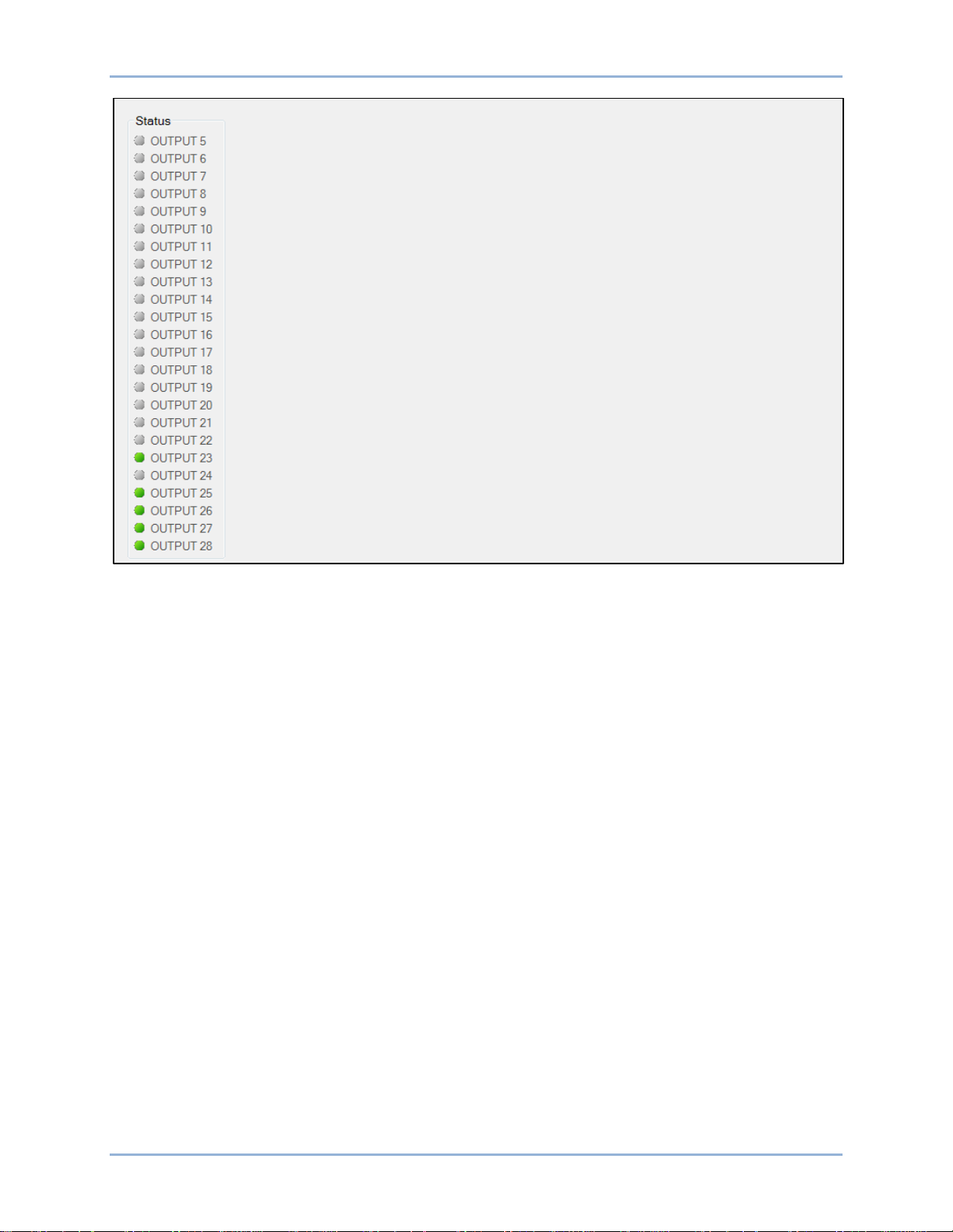
9469200990 Rev C 67
Figure 36. Metering Explorer, Outputs, Remote Contact Outputs Screen
Configurable Elements
This screen indicates the status of configurable elements. It also indicates alarms and pre-alarms of
configurable elements. The status is TRUE when the corresponding indicator is green. See Figure 37.
The Configurable Elements screen is found in the BESTCOMS Plus Metering Explorer under the Outputs
category. If using the front panel, navigate to Metering > Alarms-Status > Configurable Elements.
DGC-2020ES Metering
Page 76

68 9469200990 Rev C
Figure 37. Metering Explorer, Outputs, Configurable Elements Screen
Control
Controls for stopping/starting the engine, opening/closing breakers, and opening/closing switches are
accessed using BESTCOMSPlus through the Metering Explorer, Control screen. This set of controls is
especially useful when commissioning the DGC-2020ES. The PC or laptop running BESTCOMSPlus
must be connected to the DGC-2020ES via the USB port (see the Communication chapter for details).
When running BESTCOM S Plus in Live mode, these buttons interact with the DGC-2020ES in real time.
Otherwise, you will be prompted before the settings are sent.
Using the Metering Explorer in BESTCOMSPlus, open the Control branch. Refer to Figure 38.
Emergency Stop
The user has control to stop the generator in case of emergency by clicking on the Emergency Stop
button.
Engine Control
The engine can be started and stopped by cl ick ing on the Start and Stop buttons. This function requires a
connection to a properly configured ECU via J1939 (CANBus).
Run, Auto, Off
The operating mode can be set to Run, Auto, or Off.
Generator and Mains Breakers
There are controls for opening and closing the generator breaker and mains breaker. The breaker is open
when the corresponding indicator is green and closed when red. This function requires that the Generator
and Mains breakers be configured.
Metering DGC-2020ES
Page 77

9469200990 Rev C 69
Switches 1 through 4
Each of these switches can be opened or closed by clicking on the Open or Close buttons. The switch is
closed when the corresponding indicator is red. These buttons control the virtual inputs found in
BESTlogicPlus Programmable Logic. The number of the switch corresponds to the number of the virtual
input it controls. See the BESTlogicPlus chapter for more information.
Figure 38. Metering Explorer, Control Screen
Mains Fail Transfer Stat us
The Mains Fail Transfer Status screen (Figure 39) displays the Mains Fail Transfer State and any timers
relevant to the mains fail transfer process. These parameters are listed below.
Mains Fail Transfer State: The different mains fail transfer states are described below.
Power From Mains: Power is being supplied to the load from the mains bus.
Transfer Timer Active: Transfer Delay timer is actively counting.
Transferring to Gens: Load is being transferred to the generator bus.
Power From Gens: Power is being supplied to the load from the generator bus.
Return Timer Active: Return Delay timer is actively counting.
Transferring to Mains: Load is being transferred to the mains bus.
Disabled: DGC-2020ES is in the OFF or RUN operating mode or in the alarm state.
Remaining Transfer Delay: Displays the current timer value in seconds.
Remaining Return Delay: Displays the current timer value in seconds.
DGC-2020ES Metering
Page 78

70 9469200990 Rev C
Figure 39. Metering, Mains Fail Transfer Status
Auto Export Metering
This function automatically exports metering data over a user-defined period when a DGC-2020ES
connection is active. To display the Auto Export Metering screen, click the Tools pull-down menu from the
upper menu bar and click Auto Export Metering. Specify the Number of Ex ports and the Interval between
each export. Enter a filename for the metering data and a folder in which to save. The file is saved in
.CSV (comma separated values) format. The first export is performed immediately after clicking the Start
button. Click the Filter button to select specific metering screens.
Metering DGC-2020ES
Page 79

9469200990 Rev C 71
Name
Description
Alarms
AUTO RESTART FAIL
Automatic Restart Failure
BATT CHRG FAIL
Battery Charger Fail
ECU SHUTDOWN
ECU Shutdown
EMERGENCY STOP
Emergency Shutdown
FUEL LEAK DETECT
Fuel Leak Detected
GEN TRANSFER FL
Transfer Fail
GLBL ALARM
Global Alarm
GLBL SNDR FAIL
Global Sender Fail
HI COOLANT TMP
High Coolant Temp
LOST ECU COMM
Loss of ECU Communication
LOW COOL LEVEL
Low Coolant Level
LOW FUEL LEVEL
Low Fuel Level
LOW OIL PRES
Low Oil Pressure
OVERCRANK
Overcrank
OVERSPEED
Overspeed
UNEXPECTED SHUTDN
Unexpected Shutdown
Pre-alarms
BATT CHRG FAIL
Battery Charger Fail
BATT OVERVOLT
Battery Overvoltage
BUS REV ROT
Reverse Bus Rotation
Reporting and Alarms
The DGC-2020ES monitors ECU data, generator protection functions, and engine senders. An alarm or
pre-alarm is annunciated when the monitored parameter exceeds its threshold settings.
When an alarm condition exists, the engine is stopped by opening the Fuel output contact. An existing
pre-alarm condition is annunciated only.
When alarms are active, the front panel Overview screen is replaced by the Active Alarms screen. When
only pre-alarms are active, the front panel Overview screen is alternated with the Ac tiv e Pr e-Alarms
screen in one-second intervals. Active alarms and pre-alarms can be viewed through BESTCOMSPlus
The front panel Alarm LED is illuminated when alarms are active. When pre-alarms are active, the Alarm
LED flashes in one-sec o nd interv a ls .
If programmed and enabled, the horn output is closed when alarms are active. When pre-alarms are
active, the horn output toggles in one-sec ond int erv als .
Active alarms are also indicated on the optional remote display panel in the form of LEDs and an audible
horn. Red alarm LEDs light and the horn sounds when the corresponding alarm setting is exceeded. If an
active alarm condition is not annunciated by the remote display panel, the Switch Not In Auto LED lights
and the horn sounds.
Each alarm provides a logic output that can be connected to a physical output or other logic input usin g
BESTlogic™Plus Programmable Logic.
®
.
A detailed list of alarms is provided in Table 6.
Table 6. Available Alarms
DGC-2020ES Reporting and Alarms
Page 80

72 9469200990 Rev C
Name
Description
CEM COMM FAIL
CEM Communication Failure
CEM HW MISMATCH
CEM Hardware Mismatch
CHECKSUM FAIL
Checksum Failure
DEF ENGINE DERATE
DEF Engine Derate
DEF FLUID EMPTY
DEF Fluid Empty
DEF FLUID LOW
DEF Fluid Low
DEF INDUCMT O-RIDE
DEF Inducement Override
DEF PRESVR INDUCMT
DEF Pre-Severe Induc eme nt
DEF SEVERE INDUCMT
DEF Severe Inducement
DIAG TRBL CODE
Active DTC
DPF REGEN INHBTD
DPF Regenerate Disabled
DPF REGEN REQD
DPF Regenerate Required
DPF SOOT HIGH
DPF Soot Level High
DPF SOOT LVL EXT HI
DPF Soot Level Severely High
DPF SOOT LVL MOD HI
DPF Soot Level Moderately High
FUEL 1 LEAK
Fuel Filter 1 Leak
FUEL 2 LEAK
Fuel Filter 2 Leak
FUEL LEAK DETECT
Fuel Leak Detect
GEN REV ROT
Reverse Generator Rotation
GN BRK CL FL
Breaker Close Failure
GN BRK OP FL
Breaker Open Failure
HI COOLANT TMP
High Coolant Temp
HIGH EXHAUST TEMP
High Exhaust Temperature
HIGH FUEL LEVEL
High Fuel Level
LOST ECU COMM
Loss of ECU Communication
LOW BATT VOLT
Low Battery Voltage
LOW COOL LEVEL
Low Coolant Level
LOW COOL TMP
Low Coolant Temp
LOW FUEL LEVEL
Low Fuel Level
LOW OIL PRES
Low Oil Pressure
MAINT INTERVAL
Maintenance Interval
MPU FAIL
MPU Failure
MULTIPLE CEM
Duplicate CEM
SERFLASH RD FAIL
Serial Flash Read Failure
WEAK BATTERY
Weak Battery Voltage
Sender Fail
COOL SNDR FAIL
Coolant Temp Sender Fail
FUEL LEVEL SNDR
Fuel Level Sender Fail
LOSS OF VOLT
Voltage Sensing Fail
Reporting and Alarms DGC-2020ES
Page 81

9469200990 Rev C 73
Name
Description
OIL SNDR FAIL
Oil Pressure Sender Fail
SPD SNDR FAIL
Speed Sender Fail
Generator Protection
27 UNDVOLT TRP
Undervoltage (27)
47 PHS IMBAL TRP
Phase Imbalance (47)
50 OVRCURR TRP
Overcurrent (50)
59 OVRVOLT TRP
Overvoltage (59)
81O OVRFREQ TRP
Frequency (81O)
81U UNDFREQ TRP
Frequency (81U)
Alarm Configuration
Alarms, pre-alarms, sender failure alarms, and the audible horn can be configured through
BESTCOMSPlus or the front panel.
Alarms
To configure alarms using BESTCOMSPlus, open the Alarm screen (Figure 40). This screen is found in
the Settings Explorer under the Alarm Configuration category. If using the front panel, navigate to
Settings > Alarm Configuration > Alarms .
Figure 40. Settings Explorer, Alarm Configuration, Alarms Screen
The alarm settings are described below.
High Coolant Temp
High coolant temperature alarm settings consist of an enable/disable setting, a threshold setting, and an
arming delay. If enabled, a high coolant temperature alarm is triggered after a four second delay when the
engine coolant temperature exceeds the threshold setting. The arming delay disables the high coolant
temperature alarm function for a user-adjustable period after engine startup. System units are configured
on the System Settings screen.
DGC-2020ES Reporting and Alarms
Page 82

74 9469200990 Rev C
Low Oil Pressure
Low oil pressure alarm settings consist of an enable/disable setting, a thres h old setting, and an ar mi ng
delay. If enabled, a low oil pressure alarm is triggered after a two second delay when the engine oil
pressure decreases below the threshold setting. The arming delay disables the low oil pressure alarm
function for a user-adjustable period after engine startup. System units and metric pressure units are
configured on the System Settings scr een .
Overspeed
Overspeed alarm settings include an enable/disable setting, a threshold setting, and an activation delay.
If enabled, an overspeed alarm occurs when the engine speed (in rpm) exceeds the threshold setting for
the duration of the activation time delay.
Low Fuel Level
Low fuel level alarm settings consist of an enable/disable setting, a threshold setting, and an activation
delay setting. If enabled, a low fuel level alarm is triggered when the metered fuel level drops below the
threshold setting for the duration of the activation time delay.
Low Coolant Level
Low coolant level alarm settings consist of an enable/disable setting and a threshold setting. If enabled, a
low coolant level alarm is triggered when the metered coolant level drops below the threshold setting.
ECU Support must be enabled on the Communications, CAN Bus, CAN Bus Setup screen before this
alarm can be configured.
Pre-alarms
To configure pre-alarms using BESTCOMSPlus, open the Pre-Alarms screen (Figure 41). This screen is
found in the Settings Ex plor er under the Alarm Configuration category. If using the front panel, navigate to
Settings > Alarm Configuration > Pre-alarms.
The pre-alarm settings are desc ribed be low.
High Fuel Level
High fuel level pre-alarm settings consist of an enable/disable setting, a threshold setting, and an
activation delay. If enabled, a high fuel level pre-alarm is triggered when the metered fuel level increases
above the threshold setting for the duration of the activation delay.
Low Fuel Level
Low fuel level pre-alarm settings consist of an enable/disable setting and a threshold setting. If enabled, a
low fuel level pre-alarm is triggered when the metered fuel level decreases below the threshold setting.
Low Battery Voltage
Low battery voltage pre-alarm settings consist of an enable/disable setting, a threshold setting, and an
activation delay. If enabled, a low battery voltage pre-alarm is triggered when the battery voltage
decreases below the threshold setting for the duration of the activation time delay. The threshold can be
entered in actual volts or a per-unit value. The per-unit threshold value is based on the nominal battery
voltage setting found on the System Parameters, Rated Data screen.
High Coolant Temp
High coolant temperature pre-alarm settings consist of an enable/disable setting and a threshold setting.
If enabled, a high coolant temperature pre-alarm is annunciated when the engine coolant temperature
exceeds the threshold setting for a fixed duration of four seconds. The arming delay disables the High
Coolant Temp pre-alarm function for a user-adjustable time during engine startup. Delay duration is
determined by the High Coolant Temp Alarm Arming Delay setting. System units are configured on the
System Settings screen.
Reporting and Alarms DGC-2020ES
Page 83

9469200990 Rev C 75
Weak Battery Voltage
Weak battery voltage pre-alarm settings consist of an enable/disable setting, a threshold setting, and an
activation time delay. If enabled, a weak battery voltage pre-a larm latc h es duri ng eng ine cranking when
the battery voltage decreases below the threshold setting for the duration of the activation delay. The
threshold can be entered in actual volts or a per-unit value. The per-unit threshold value is based on the
nominal battery voltage setting found on the System Parameters, Rated Data screen.
Low Coolant Temp
Low coolant temperature pre-alarm settings consist of an enable/disable setting and a threshold setting. If
enabled, a low coolant temperature pre-alar m occ ur s when the engine coolant temperature decreases
below the threshold setting. System units are configured on the System Settings screen.
Battery Overvoltage
Battery overvoltage pre-alarm settings consist of an enable/disable setting and a threshold setting. If
enabled, a battery overvoltage pre-alarm occurs when the battery voltage increases above the threshold
setting. The threshold can be entered in actual volts or a per-unit value. The per-unit threshold value is
based on the nominal battery voltage setting found on the Sys tem Param eter s , Rated D ata screen.
ECU Coms Fail
ECU communication failure pre-alarm settings consist of a single enable/disable setting. If enabled, this
pre-alarm is triggered when the DGC-2020ES detects a problem in its J1939 CAN connec t ion to the ECU.
Coolant Level
Low coolant level pre-alarm settings consist of an enable/disable setting and a threshold setting. If
enabled, a low coolant level pre-alarm is triggered when the metered coolant level decreases below the
threshold setting.
Maintenance Interval
Maintenance interval pre-alarm settings consist of an enable/disable setting and a threshold setting. If
enabled, a maintenance interval pre-alarm is annunciated when the DGC-2020ES mainte nanc e ti mer
counts down to zero from the threshold time setting.
Active DTC
Active DTC (diagnostic trouble code) pre-alarm settings consist of a single enable/disable setting. If
J1939 CAN and DTC support are both enabled, an “active DTC” pre-alarm can be enabled. This prealarm is triggered when a DTC is sent from the ECU to the DGC-2020ES.
Low Oil Pressure
Low oil pressure pre-alarm settings consist of an enable/disable setting and a threshold setting. If
enabled, a low oil pressure pre-alarm is triggered after a two second delay when the engine oil pressure
decreases below the threshold setting. The arming delay disables the low oil pressure pre-alarm function
for a user-adjustable time during engine startup. Delay duration is determined by the Low Oil Pressure
Alarm Arming Delay setting. System units and metric pressure units are configured on the System
Settings screen.
CEM Comm Failure
CEM-2020 communication failure pre-alarm settings consist of a single enable/disable setting. If enabled,
this pre-alarm is triggered when communication between the optional CEM-2020 and DGC-2020ES is
lost.
Checksum Failure
When one of the internal checksum calculations, used for data integrity purposes, has failed, the
checksum failure pre-alarm is triggered. This indicates that some of the user settings or firmware code
has been corrupted.
DGC-2020ES Reporting and Alarms
Page 84

76 9469200990 Rev C
After upgrading firmware through BESTCOMSPlus, the checksum failure pre-alarm may trigger. This prealarm is not indicative of an error in this case. It can be cleared by cycling power to the DGC-2020ES. If
the pre-alarm reoccurs, then it is indicative of an error and corrective action should be taken. See
Resetting Alarms, Checksum Failure, below, for more information.
Breaker Close Failure
If enabled, this pre-alarm is triggered when the DGC-2020ES has issued a "breaker close" output and has
not received "breaker closed" feedback from the breaker within the allowed closing time. The Monitor
setting determines whether this condition is monitored only during transitions or always.
Breaker Open Failure
If enabled, this pre-alarm is triggered when the DGC-2020ES has issued a "breaker open" output and has
not received "breaker opened" feedback from the breaker within the allowed closing time. The Monitor
setting determines whether this condition is monitored only during transitions or always.
Reverse Rotation
If enabled, this pre-alarm is triggered when the Generator or Bus rotation is opposite of the Phase
Rotation setting defined on the Rated Data screen.
Reporting and Alarms DGC-2020ES
Page 85

9469200990 Rev C 77
Figure 41. Settings Explorer, Alarm Configuration, Pre-Alarms Screen
Horn Configuration
To configure the audible horn using BESTCOMSPlus, open the Horn Configuration screen (Figure 42).
This screen is found in the Settings Explorer under the Alarm Configuration category. If using the front
panel, navigate to Settings > Alarm Config uration > Horn Configuration.
An output contact is configured through programmable logic to energize an audible horn when an alarm
or pre-alarm condition exists. The horn settings consist of an enable/disable setting and a Not in Auto
enable/disable setting. If enabled, the contact output is closed when an alarm condition exists. The
contact output is toggled between open and closed when a pre-alarm condition exists. If the Not in Auto
setting is enabled, the horn is disabled w hen the DGC-2020ES is not operating in Auto mode.
DGC-2020ES Reporting and Alarms
Page 86

78 9469200990 Rev C
Figure 42. Settings Explorer, Alarm Configuration, Horn Configuration Screen
Sender Failure
To configure sender failure alarms using BESTCOMSPlus, open the Sender Fail screen (Figure 43). This
screen is found in the Settings Explorer under the Alarm Configuration category. If using the front panel,
navigate to Settings > Alarm Configuration > Sender Fail.
Coolant temperature, oil pressure, fuel level, and voltage sensing sender failure settings consist of an
alarm configuration setting and an activation del ay . The alarm configuration setting allows selection of the
type of alarm to be annunciated when a sender fail condition exists. None, Alarm, and Pre-alarm can be
selected. The selected alarm type is triggered when a sender failure exists for the duration of the
activation time delay.
Speed sender failure settings consist of a single activation delay. An alarm is triggered when a speed
sender failure exists for the duration of the activation time delay.
Figure 43. Settings Explorer, Alarm Configuration, Sender Fail Screen
Retrieving Alarm Information
Alarms can be viewed on the front panel display and through BESTCOMSPlus.
Front Panel Display
The lists of active alarms and pre-alarms can be viewed by navigating to Metering > Alarms-Status >
Active Alarms or Active Pre-alarms. These lists are scrollable by using the Up and Down pushbuttons.
Reporting and Alarms DGC-2020ES
Page 87

9469200990 Rev C 79
BESTCOMSPlus®
The status of each alarm and pre-alarm is displayed on the Alarms screen (Figure 44). This screen is
found in the Metering Ex plo rer . Alarms with a red indicator are active.
Figure 44. Metering Explorer, Alarms Screen
Resetting Alarms and Pr e -Alarms
Most pre-alarms automatically reset when the alarm condition no longer exists. Pre-alarms that do not
automatically reset are listed below:
• Weak Battery
• Breaker Fail to Open
• Breaker Fail to Close
These pre-alarms are reset by navigating to the Overview screen on the front panel display and holding
the Back pushbutton for two seconds.
Alarms do not automatically reset. Manually reset alarms by pressing the Off pushbutton.
Horn
The audible horn can be silenced by simultaneously pressing the Back and Edit pushbuttons. This does
not reset the alarm or pre-alarm causing the horn to annunciate.
Maintenance Interval
To reset the maintenance interval pre-alarm through the front panel, navigate to the Settings > System
Params > System Settings > Maint Reset screen. Operator, Settings, or OEM access level is required to
reset the maintenance interval pre-alarm. If the maintenance interval pre-alarm is not enabled, the Maint
Reset parameter is not visible on the front panel.
To reset the maintenance interval pre-alarm by using BESTCOMSPlus, use the Metering Explorer to
open the Run Statistics screen and click on the Reset Maintenance Interval button.
To reset the maintenance i nter v al pre-alarm from the front panel, navigate to the Overview screen and
hold the Back pushbutton for 12 seconds.
DGC-2020ES Reporting and Alarms
Page 88

80 9469200990 Rev C
Caution
Checksum Failure
The checksum failure pre-alarm can be cleared by holding the Back pushbutton for two seconds while
displaying the Overview screen. However, the pre-alarm will reoccur the next time the checksum is
verified if the data is still corrupted. Some checksum calculations are done only on power-up, so this may
not occur until the next time operating power is cycled.
If there are consistent checksum failure pre-alarms, attempt the following actions to correct the problem:
1. Load default settings by holding the Up and Down pushbuttons on the front panel while cycling
power. After loading defaults, upload the se tti ngs file th rough BE STCO M S Plus if necessary.
Loading default settings will erase all custom settings. All reports and
events will be cleared. It is recommended that all settings are
downloaded and saved through BESTCOMSPlus before attempting to
load defaults. Once defaults are loaded, the saved settings can then
be uploaded.
2. If the problem persists, reload the firmware file through BESTCOMSPlus. See the
BESTCOMSPlus chapter for more information.
3. Contact Basler Electric Technical Support.
4. The checksum failure pre-alarm can be d isabled. This disables on ly the annunciation of the pre-
alarm and does not correct any error conditions.
Reporting and Alarms DGC-2020ES
Page 89

9469200990 Rev C 81
Event Recording
An event log retains history of system events in nonvolatile memory. Fifty event records are retained and
each record contains a time stamp of the first and last event occurrence, and the number of occurrences
for each event. In addition, each record contains details of the time, date, and engine hours for the most
recent 30 occurrences of the event. The number of occurrences stops incrementing at 99. If an event
occurs which is of a type that differs from those in the 50 records in memory, the record that has the
oldest “last” event occurrence is removed from the log, and the new category takes its place. Since 50
event records with up to 99 occurrences each are retained in memory, a history of nearly 5,000 specific
events are retained by the DGC-2020ES. Detailed occurrence information is retained for the most recent
30 occurrences of each event record, and there are 50 event records. Thus the time, date, and engine
hours details for up to 1,500 specific event occurrences are retained in the event log.
Event Log
An event log can be downloaded into BESTCO M S Plus® for viewing and storage. The Options button is
used to save the entire event log to a file, or to save the list to the computer clipboard making it available
for insertion into other software applications. It is possible to copy a portion of the log to the computer
clipboard by selecting the desired portion with the mouse then using the Options->Copy Selection feature.
The Download button refreshes the event log list by performing a fresh download of the list from the DGC2020ES. The Clear button gives the user the option of clearing selected or all event logs. Refer to Figure
45.
Figure 45. Metering Explorer, Event Log Screen (Sorted by Event ID)
The event log may also be viewed on the front pan el display by navigating to Metering, Alarms-Status,
Event Log. Use the Up/Down keys to highlight an event and press the Right key to view the summary of
that event record. The summary contains the description of the event, date, time, and engine hours of the
first occurrence of the event, along with date, time, and engine hours of the most recent occurrence of the
event. To view details of specific event occurrences, press the Down key until DETAILS is highlighted,
and then, press the Right key. The occurrence number can be changed by pressing the Edit key,
Up/Down keys to select #, and pressing the Edit key again to exit. Table 7 lists all possible event strings
(as shown in the event log).
DGC-2020ES Event Recording
Page 90

82 9469200990 Rev C
Event String
Event Description
Event Type
27 UNDVOLT TRP A
27 Undervoltage Trip
Alarm
27 UNDVOLT TRP P
27 Undervoltage Trip
Pre-Alarm
47 PHS IMBAL TRP A
47 Phase Imbalance Trip
Alarm
47 PHS IMBAL TRP P
47 Phase Imbalance Trip
Pre-Alarm
50 OVRCURR TRP A
50 Overcurrent Trip
Alarm
50 OVRCURR TRP P
50 Overcurrent Trip
Pre-Alarm
59 OVRVOLT TRP A
59 Overvoltage Trip
Alarm
59 OVRVOLT TRP P
59 Overvoltage Trip
Pre-Alarm
81O OVRFREQ TRP A
81 Overfrequency Trip
Alarm
81O OVRFREQ TRP P
81 Overfrequency Trip
Pre-Alarm
81U UNDFREQ TRP A
81 Underfrequency Trip
Alarm
81U UNDFREQ TRP P
81 Underfrequency Trip
Pre-Alarm
ATS INPUT CLOSED
ATS Input
Status
AUTO RESTART
Automatic Restart in Progress
Status
AUTO RESTART FAIL A
Automatic Restart Fail
Alarm
BATT CHRG FAIL A
Battery Charger Fail
Alarm
BATT CHRG FAIL P
Battery Charger Fail
Pre-Alarm
BATT OVERVOLT P
Battery Overvoltage
Pre-Alarm
BATTLE OVERRIDE
Battle Override
Status
CAN BUS OFF
CAN Bus entered Bus Off state
Status
CAN ERROR PASSIVE
CAN Bus entered Error Passive state
Status
CEM COMM FAIL P
CEM-2020 Communications Failure
Pre-Alarm
CEM HW MISMATCH P
Connected CEM-2020 is wrong type
Pre-Alarm
CHECKSUM FAIL P
Corrupt user settings or firmware code
Pre-Alarm
COMBINED RED A
Combined Red
Alarm
COMBINED YELLOW P
Combined Yellow
Pre-Alarm
CONFIG ELEMENT X A (X = 1 to 8)
Configurable Element X (X = 1 to 8)
Alarm
CONFIG ELEMENT X P (X = 1 to 8)
Configurable Element X (X = 1 to 8)
Pre-Alarm
COOL LVL SNDR FL A
Coolant Level Sender Fail
Alarm
COOL SNDR FAIL
Coolant Temperature Sender Fail
Status
COOL SNDR FAIL A
Coolant Temperature Sender Fail
Alarm
COOL SNDR FAIL P
Coolant Temperature Sender Fail
Pre-Alarm
DEF ENGINE DERATE P
Diesel Exhaust Fluid Engine Derate
Pre-Alarm
DEF FLUID EMPTY P
Diesel Exhaust Fluid Empty
Pre-Alarm
DEF FLUID LOW P
Diesel Exhaust Fluid Low
Pre-Alarm
DEF INDUCMT O-RIDE P
Diesel Exhaust Fluid Inducement Override
Pre-Alarm
DEF PRESVR INDUCMT P
Diesel Exhaust Fluid Pre-Severe Inducement
Pre-Alarm
DEF SEVERE INDUCMT P
Diesel Exhaust Fluid Severe inducement
Pre-Alarm
DGC HEARTBEAT FAIL P
DGC Heartbeat Fail
Pre-Alarm
DIAG TRBL CODE P
Diagnostic Trouble Code
Pre-Alarm
DPF REGNRATE DISABLD P
Diesel Particulate Filter Regeneration Disabled
Pre-Alarm
DPF REGEN REQD P
Diesel Particulate Filter Regeneration Required
Pre-Alarm
Table 7. Event List
Event Recording DGC-2020ES
Page 91

9469200990 Rev C 83
Event String
Event Description
Event Type
DPF SOOT LVL EXT HI P
Diesel Particulate Filter Soot Level Extremely High
Pre-Alarm
DPF SOOT LVL MOD HI P
Diesel Particulate Filter Soot Level Moderately High
Pre-Alarm
ECU SHUTDOWN A
ECU Shutdown
Alarm
EMERGENCY STOP A
Emergency Stop
Alarm
ENGINE RUNNING
Engine Running
Status
FUEL FLT PRS HI P
Fuel Filter Differential Pressure High
Pre-Alarm
FUEL LEAK 1 P
Fuel Filter 1 Leak
Pre-Alarm
FUEL LEAK 2 P
Fuel Filter 2 Leak
Pre-Alarm
FUEL LEAK DETECT A
Fuel Leak Detect
Alarm
FUEL LEAK DETECT P
Fuel Leak Detect
Pre-Alarm
FUEL LEVL SENDR A
Fuel Level Sender Fail
Alarm
FUEL LEVL SENDR FAIL
Fuel Level Sender Fail
Status
FUEL LEVL SENDR P
Fuel Level Sender Fail
Pre-Alarm
GEN TEST LOADED
Generator Exerciser Test with Load
Status
GEN TEST UNLOADED
Generator Exerciser Test without Load
Status
GLBL SNDR FAIL A
Global Sender Fail
Alarm
GN BKR CL FL P
Generator Breaker Fail to Close
Pre-Alarm
GN BKR OP FL P
Generator Breaker Fail to Open
Pre-Alarm
GN BKR SYN FL P
Generator Breaker Synchronization Fail
Pre-Alarm
HI COOLANT TMP A
High Coolant Temp
Alarm
HI COOLANT TMP P
High Coolant Temp
Pre-Alarm
HI DAY TANK LEVEL P
High Day Tank Level
Pre-Alarm
HI ECU VOLTS A
High ECU Supply Voltage
Alarm
HI EXHAUSE B T P
High Exhaust Temp B
Pre-Alarm
HI EXHAUST A T P
High Exhaust Temp A
Pre-Alarm
HI PRESSURE IN 1 P
High Pressure Input 1
Pre-Alarm
HI PRESSURE IN 2 P
High Pressure Input 2
Pre-Alarm
HI SUPPLY VOLTS P
High Voltage Supply
Pre-Alarm
HI T FUEL P
High Fuel Temp
Pre-Alarm
HIGH AMB TEMP P
High Ambient Temp
Pre-Alarm
HIGH CHARGE AIR TEMP A
High Charge Air Temp
Alarm
HIGH CHARGE AIR TEMP P
High Charge Air Temp
Pre-Alarm
HIGH COIL TEMP 1 P
High Temp Coil 1
Pre-Alarm
HIGH COIL TEMP 2 P
High Temp Coil 2
Pre-Alarm
HIGH COIL TEMP 3 P
High Temp Coil 3
Pre-Alarm
HIGH COOLANT TEMP A
High Coolant Temp
Alarm
HIGH COOLANT TEMP P
High Coolant Temp
Pre-Alarm
HIGH ECU TEMPERATURE P
High ECU Temp
Pre-Alarm
HIGH EXHAUST TEMP P
High Exhaust Temp
Pre-Alarm
HIGH FUEL LEVEL P
High Fuel Level
Pre-Alarm
HIGH FUEL RAIL PRESS P
High Fuel Rail Pressure
Pre-Alarm
HIGH INTRCOOLER TEMP P
High Intercooler Temp
Pre-Alarm
HIGH OIL TEMPERATURE P
High Oil Temp
Pre-Alarm
DGC-2020ES Event Recording
Page 92

84 9469200990 Rev C
Event String
Event Description
Event Type
HIGH OIL TERMPERATURE A
High Oil Temp
Alarm
HIGH STRG TANK LEVEL P
High Storage Tank Level
Pre-Alarm
IDLE SPD LO P
Idle Speed Low
Pre-Alarm
INPUT X A (X = 1 to 17)
User Configurable Input X (X = 1 to 17)
Alarm
INPUT X P (X = 1 to 17)
User Configurable Input X (X = 1 to 17)
Pre-Alarm
LO AFTERCLR COOL LVL A
Low After Cooler Cool Level
Alarm
LO CHG AIR CLNT LVL P
Low Charge Air Coolant Level
Pre-Alarm
LO DAY TANK LEVEL P
Low Day Tank Level
Pre-Alarm
LO ECU VOLTS P
Low ECU Supply Voltage
Pre-Alarm
LO FUEL DLV PRESSURE A
Low Fuel Delivery Pressure
Alarm
LO SUPPLY VOLTS P
Low Voltage Supply
Pre-Alarm
LOAD TAKEOVER
Load Takeover
Status
LOGIC OUPUT A
Logic Output
Alarm
LOGIC OUPUT P
Logic Output
Pre-Alarm
LOSS OF VOLT
Voltage Sensing Fail
Status
LOSS OF VOLT A
Voltage Sensing Fail
Alarm
LOSS OF VOLT P
Voltage Sensing Fail
Pre-Alarm
LOSS REM COMS P
Loss of Remote Module Communication
Pre-Alarm
LOST ECU COMM A
Loss of ECU Communication
Alarm
LOST ECU COMM P
Loss of ECU Communication
Pre-Alarm
LOW BATT VOLT P
Low Battery Voltage
Pre-Alarm
LOW CHARGE AIR PRESS P
Low Charge Air Pressure
Pre-Alarm
LOW COOL LEVEL A
Low Coolant Level
Alarm
LOW COOL LEVEL P
Low Coolant Level
Pre-Alarm
LOW COOL TMP A
Low Coolant Temperature
Alarm
LOW COOL TMP P
Low Coolant Temperature
Pre-Alarm
LOW COOLANT LEVEL P
Low Coolant Level
Pre-Alarm
LOW FUEL DELIV PRESS P
Low Fuel Delivery Pressure
Pre-Alarm
LOW FUEL LEVEL A
Low Fuel Level
Alarm
LOW FUEL LEVEL P
Low Fuel Level
Pre-Alarm
LOW FUEL RAIL PRESS P
Low Fuel Rail Pressure
Pre-Alarm
LOW OIL PRES A
Low Oil Pressure
Alarm
LOW OIL PRES P
Low Oil Pressure
Pre-Alarm
LOW OIL PRESSURE A
Low Oil Pressure
Alarm
LOW OIL PRESSURE P
Low Oil Pressure
Pre-Alarm
LOW STRG TANK LEVEL P
Low Storage Tank Level
Pre-Alarm
MAINS FAIL TEST
Mains Fail Test
Status
MAINT INTERVAL P
Maintenance Interval
Pre-Alarm
MF TRANSFER
Mains Fail Transfer Complete
Status
MF TRANSFER FAIL
Mains Fail Transfer Fail
Status
MN BKR CL FL P
Mains Br eaker Fail t o Close
Pre-Alarm
MN BKR OP FL P
Mains Breaker Fail to Open
Pre-Alarm
MPU FAIL P
Magnetic Pickup Fail
Pre-Alarm
Event Recording DGC-2020ES
Page 93

9469200990 Rev C 85
Event String
Event Description
Event Type
MULTIPLE CEM P
Multiple CEM-2020’s
Pre-Alarm
NORM SHUTDOWN
Normal Shutdown
Status
OIL SNDR FAIL
Oil Pressure Sender Fail
Status
OIL SNDR FAIL A
Oil Pressure Sender Fail
Alarm
OIL SNDR FAIL P
Oil Pressure Sender Fail
Pre-Alarm
OVERCRANK A
Overcrank
Alarm
OVERSPD TEST ON P
Overspeed Test On
Pre-Alarm
OVERSPEED A
Overspeed
Alarm
PRIMING FAULT P
Priming Fault
Pre-Alarm
PROT SHUTDOWN
Protective Shutdown
Status
REV BUS ROT P
Reverse Bus Rotation
Pre-Alarm
REV GEN ROT P
Reverse Generator Rotation
Pre-Alarm
RUNUP SPD LO P
Run Up Speed Low
Pre-Alarm
SERFLASH RD FAIL
Serial Flash Read Fail
Pre-Alarm
SPD SNDR FAIL
Speed Sender Fail
Status
SPD SNDR FAIL A
Speed Sender Fail
Alarm
SPEED DMD FL P
Speed Demand Fail
Pre-Alarm
SPEED TOO LOW P
Engine Speed Too Low
Pre-Alarm
SS OVERRIDE ON P
Shutdown Override
Pre-Alarm
START SPEED LOW P
Start Speed Low
Pre-Alarm
VOLTAGE SENSE FAIL
Voltage Sensing Fail
Status
VOLTAGE SENSE FAIL A
Voltage Sensing Fail
Alarm
VOLTAGE SENSE FAIL P
Voltage Sensing Fail
Pre-Alarm
WEAK BATTERY P
Weak Battery
Pre-Alarm
DGC-2020ES Event Recording
Page 94

86 9469200990 Rev C
Event Recording DGC-2020ES
Page 95

9469200990 Rev C 87
P0067-98
7.433 (188.8) max
7.393 (187.8) min
7.635 (194.0) max
7.615 (193.4) min
5.635 (143.2) max
5.615 (142.6) min
5.433 (138) max
5.393 (137) min
0.218 (5.5) diameter
CUTOUT
0.242 (6.2) max
0.182 (4.6) min
0.242 (6.2) max
0.182 (4.6) min
0.320 (8.1) max
0.280 (7.1) min
45°
Mounting
DGC-2020ES controllers are delivered in sturdy cartons to prevent shipping damage. Upon receipt of a
unit, check the part number against the requisition and packing list for agreement. Inspect for damage,
and if there is evidence of such, immediately file a claim with the carrier and notify the Basler Electric
regional sales office or your sales representative.
If the device is not installed immediately, store it in the original shipping package in a moisture- and dustfree environment.
Hardware
The front panel is resistant to moisture, salt fog, humidity, dust, dirt, and chemical contaminants. DGC2020ES controllers are mounted using the four permanently attached 10-24 studs. The torque applied to
the mounting hardware should not exceed 20 inch-pounds (2.2 newton meters).
Dimensions
Panel cutting and drilling dimensions are shown in Figure 46. Overall dimensions are shown in Figure 47.
All dimensions are shown in inches with millimeters in parenthesis.
Figure 46. Panel Cutting and Drilling Dimensions
DGC-2020ES Mounting
Page 96

88 9469200990 Rev C
Figure 47. Overall Dimensions
Mounting DGC-2020ES
Page 97

9469200990 Rev C 89
Terminals and Connectors
All DGC-2020ES terminals and connectors are located on the rear panel. DGC-2020ES terminals consist
of a mini-B USB socket and plug-in connectors with spring clamp terminals.
Figure 48 illustrates the rear panel terminals. Locator letters in the illustration correspond to the terminal
block and connector descriptions in Table 8.
Figure 48. Rear Panel
DGC-2020ES Terminals and Connectors
Page 98

90 9469200990 Rev C
Locator
Description
A
The majority of external, DGC-2020ES wiring is terminated at 8- or 15-position
maximum wire size of 12 AWG.
B
The mini-B USB socket mates with a standard USB cable and is used with a PC
running BESTCOMSPlus® software for local communication with the DGC-2020ES.
Note
Terminal
Description
16 (CHASSIS)
Chassis ground connection
17 (BATT–)
Negative side of operating power input
18 (BATT+)
Positive side of operating power input
Table 8. Rear Panel Terminal and Connector Descriptions
connectors with spring clamp terminals. These connectors plug into headers on the
DGC-2020ES. The connectors and headers have a dovetailed edge that ensures
proper connector orientation. Each connector and header is uniquely keyed to ensure
that a connector mates only with the correct header. Spring clamp terminals accept a
Connections
DGC-2020ES connections are dependent on the application. Incorrect wiring may result in damage to the
controller.
Be sure that the DGC-2020ES is hard-wired to earth ground with no
smaller than 12 AWG copper wire attached to the chassis ground
terminal (terminal 1) on the rear of the controller.
Operating power from the battery must be of the correct polarity.
Although reverse polarity will not cause damage, the DGC-2020ES will
not operate.
For the DGC-2020ES to correctly meter power factor, the generator
must be rotating clockwise (A-B-C).
The DGC-2020ES terminals are grouped by function and include operating power, generator current
sensing, generator voltage sensing, bus voltage sensing, analog engine sender inputs, magnetic pickup
input, contact sensing inputs, output contacts, USB interface, CAN interface, and Remote Display Panel
connections.
DGC-2020ES terminal groups are described in the following paragraphs.
Operating Power
The DGC-2020ES operating power input accepts either 12 Vdc or 24 Vdc and tolerates voltage over the
range of 6 to 32 Vdc. Operating power must be of the correct polarity. Although reverse polarity will not
cause damage, the DGC-2020ES will not operate. Operating power terminals are listed in Table 9.
It is recommended that a fuse be added for additional protection for the wiring to the battery input of the
DGC-2020ES. A fuse helps pr event w ire dam age and nuis a nc e trips due to initia l power supply inrus h
current. To follow UL guidelines, a 5 A maximum, 32 Vdc supplementary fuse must be implemented in the
battery input circuit to the DGC-2020ES
Table 9. Operating Power Terminals
Terminals and Connectors DGC-2020ES
Page 99

9469200990 Rev C 91
Terminals
Description
37 (IA–)
A-phase current sensing input
38 (IA+)
35 (IB–)
B-phase current sensing input
36 (IB+)
33 (IC–)
C-phase current sensing input
34 (IC+)
Note
Caution
Terminal
Description
40 (GEN VN)
Neutral generator voltage sensing input
41 (GEN VC)
C-phase generator voltage sensing input
43 (GEN VB)
B-phase generator voltage sensing input
45 (GEN VA)
A-phase generator voltage sensing input
Generator Current Sensing
The DGC-2020ES has sensing inputs for A-phase, B-phase, and C-phase generator current. A DGC2020ES with a style number of 1xx has a 1 Aac nominal current sensing and a DGC-2020ES with a style
number of 5xx indicates 5 Aac nominal current sensing. Generator current sensing terminals are listed in
Table 10.
Table 10. Generator Current Sensing Ter min als
Unused current sensing inputs should be shorted to minimize noise
pickup.
Generator current sensing terminals 37 (IA–), 35 (IB–), and 33 (IC–)
must be terminated to ground for proper opera tio n.
Generator Voltage Sensing
The DGC-2020ES accepts either line-to-line or line-to-neutral generator sensing voltage over the range of
12 to 576 volts, rms line-to-line. Generator voltage sensing terminals are listed in Table 11.
Table 11. Generator Voltage Sensing Ter min als
Bus Voltage Sensing
Sensing of bus voltage enables the DGC-2020ES to detect failures of the mains (utility). The DGC2020ES senses A-phase, B-phase, and C-phase bus voltage. Bus voltage sensing terminals are listed in
Table 12.
DGC-2020ES Terminals and Connectors
Page 100

92 9469200990 Rev C
Terminal
Description
46 (BUS VA)
A-phase bus voltage sensing input
48 (BUS VB)
B-phase bus voltage sensing input
50 (BUS VC)
C-phase bus voltage sensing input
Terminal
Description
1 (FUEL)
Fuel level sender input
2 (SENDER COM)
Sender return terminal
52 (OIL)
Oil pressure sender input
53 (COOLANT)
Coolant temperature sender input
Terminals
Description
31 (MPU–)
Magnetic pickup return input
32 (MPU+)
Magnetic pickup positive input
Terminal
Description
17 (BATT–)
Common return line for programmable contact inputs
3 (INPUT 1)
Programmable contact input 1 (ESTOP by default)
4 (INPUT 2)
Programmable contact input 2
5 (INPUT 3)
Programmable contact input 3
6 (INPUT 4)
Programmable contact input 4
7 (INPUT 5)
Programmable contact input 5
8 (INPUT 6)
Programmable contact input 6
9 (INPUT 7)
Programmable contact input 7
Table 12. Bus Voltage Sensing Terminals
Analog Engine Sender Input s
Inputs are provided for oil pressure, fuel level, and coolant temperature senders. For a listing of oil
pressure, fuel level, and coolant temperature senders that are compatible with the DGC-2020ES, refer to
the Engine Sender Inputs chapter. Analog engine sender input terminals are listed in Table 13.
Table 13. Sender Input Terminals
Magnetic Pickup Input
The magnetic pickup input accepts a speed signal over the range of 3 to 35 volts peak and 32 to 10,000
hertz. Magnetic pickup input terminals are listed in Table 14.
Table 14. Magnetic Pickup Input Terminals
Contact Sensing Inputs
Contact sensing inputs consist of seven programmable inputs. The programmable inputs accept normally
open, dry contacts. Terminal 17 (BATT–) serves as the common return line for the programmable inputs.
While input 1 is programmed to recognize an emergency stop input by default, it can be programmed for
any function. Information about configuring the programmable inputs is provided in the Contact Inputs
chapter. Contact sensing input terminals are listed in Table 15.
Table 15. Contact Sensing Inputs
Terminals and Connectors DGC-2020ES
 Loading...