

Page 1
INSTRUCTION MANUA L
FOR
DIGITAL GENSET CONTRO LL ER
DGC-2020
Publication: 9400200990
Revision: X Oct-14
Page 2

Page 3

INTRODUCTION
WARNING!
2020 settings. Instructions for changing passwords are
This instruction manu al pro vides inform ation abo ut the operation and inst allation of the DGC-2020 Digital
Genset Controller. To accomplish this, the following information is provided:
• General Information and Specifications
• Controls and Indicators
• Functional Description
• Graphical User Interface Operation
• Installation
• Setup
• Maintenance and Troubleshooting
To avoid personal injury or equipment damage, only qualified personnel should
perform the procedures in this manual.
NOTES
Check for the latest version of this instruction manual at www.basler.com
DGC-2020 controllers are moun ted using th e four permane ntly-at tached 10-24
studs and the provided self-locking nuts. Failure to use the proper 10-24
locking nuts may da mage t he stu d thr eads and/or impr operly s ecure the DG C-
2020.
Be sure that the control ler is hard-wired to earth grou nd with no smaller than
12 AWG copper wire attach ed to the c hass is groun d terminal on the rear of the
unit. When the controller is configured in a system with other devices, it is
recommended to use a separate lead to the ground bus from each unit.
The DGC-2020 utilizes pas sword protection that guards against unauthorized
changing of DGCprovided in Section 4, BESTCOMSPlus® Software, General Settings, Device
Security Setup. The default passwords are listed below.
• OEM access level: OEM
• Settings access level: SET
• Operator access level: OP
• LSM-2020 (Load Share Module)
• CEM-2020 (Contact Expansion Module)
• AEM-2020 (Analog Expans ion Mod ule)
• Time Overcurrent Characteristic Curves
• Modbus™ Communication
• PID Tuning Settings
• MTU Fault Codes
.
BOX DEFINITIONS
WARNING!
A warning box indicates a potentially hazardous situa tion which co uld result in
death or injury.
CAUTION
A caution box indicates a potentially hazar dous situation which could result in
equipment or property damage.
NOTE
A note box provides helpful information.
9400200990 Rev X DGC-2020 Introduction i
Page 4

First Printing: November 2006
OR STATUTORY WARRANTY, INCLUDING BUT NOT LIMITED TO
any products or services supplied or Web sites maintained or provided by third parties and/or
Printed in USA
Copyright © 2014 Basler Electric, Highland Illinois 62249 USA
All Rights Reserved
October 2014
CONFIDENTIAL INFORMATION
of Basler Electric, Highland Illinois, USA. It is loaned for confidential use,
subject to return on request, and with the mutual understanding th at it will not
be used in any manner detrimental to the interest of Basler Electric.
Disclaimer of Liability and Warranty
Basler Electric provides links to third-party Web sites and references to third party products and
services as a convenience in locating relative information, products, and serv ices for our users. The
existence of these links an d referenc es is not to be c onstrued as an endors ement by Basler Electric of
the content of any of these third-party sites, produc ts or services. BASLER ELECTRIC MAKES NO
EXPRESS, IMPLIED,
WARRANTY OF MERCHANTABILITY, WARRANTY OF FITNESS FOR A PAR TICULAR PURPOSE,
WARRANTY OF NONINFRINGEMENT OR THE LIKE, OR WARRANTY OF TITLE. Basler Electric
makes no representatio n of fr eedo m fr om computer viruses or of the ac cur ac y of the in forma ti on an d/or
the quality of products or services provided by thes e referenc ed products or advertis ed on these thirdparty Web sites. Basl er El ectric d i scl aim s, to th e fullest extent permi ssible by applicable law, an y
and all liability and respo nsibility for any claims o r damage that may ari se as a result of use of
linked to the Basler Electric W eb site. Basler El ectric advises site visitors that link s to Web sites not
controlled by Basler Electr ic are not subject to the privacy notice as sociated with the Basler Electric
Web site and, therefore, are advised to read the privacy policies of any third-party sites accessed
through this site.
It is not the intent ion of th is manual to cover a ll detai ls and variat ions in equipme nt, nor do es this m anual
provide data for every pos s ible c ont ing enc y regar di ng i nstal lat ion or operation. The avai labil ity and design
of all features and options are subject to modification without notice. Should further information be
required, contact Basler Electric.
For terms of service relati ng to this product and software, see the Commercial Ter ms of Products and
Services document available at www.basler.com/terms
.
Basler Electric
12570 State Route 143
Highland IL 62249-1074 USA
http://www.basler.com, info@basler.com
PHONE +1 618.654.2341 FAX +1 618.654.2351
ii DGC-2020 Introduction 9400200990 Rev X
Page 5

REVISION HISTORY
Manual
Revision and Date
X, 10/14
• Revised to support firmware package version 1.19.00 (see firmware
• Minor text edits throughout manual.
W, 04/14
• Added German and Portuguese language support.
• Increased unique recorded events to 50 from 30.
V, 03/14
• Added features of DGC-2020 hardware version 3.
• This revision was released in English language only.
U, 03/13
• Revised to support firmware package version 1.17.02 (see firmware
• Minor text edits
T, 01/13
• Revised to support firmware package version 1.17.00 (see firmware
package version history).
S, 05/12
• Revised to support firmware package version 1.15.00 (see firmware
• Added Appendix E • EXHAUST TREATMENT.
R, 10/11
• Added Disclaimer of Liability and Warranty in Introduction.
Q
• This revision letter not used.
The following inform ation provides a h istorical summary of th e changes made to this instruction manual
(9400200990), BESTCOMSPlus® software, firmware package, and hardwar e of the DGC-2020.
Change
package version history) and BESTCOMSPlus version 3.07.00 (see
BESTCOMSPlus revision history).
• Added Diagnostics under Metering Explorer in Section 4.
• Added Offline Logic Simulator in Section 5.
• Improvements to Appendix C, Tuning PID Settings.
• Replaced several BESTCOMSPlus screenshots where the layout
changed throughout manual.
• Added DGC-2000 legacy Modbus option and register table.
• Added Breaker configuration one-line diagram (front panel only) and
mains fail transfer status screen.
• Added Windows 8 compatibility and updated system recommendations
for BESTCOMSPlus and .NET framework.
• Expansion modules (AEM-2020, CEM-2020, and LSM-2020) now
have gold-plated communication terminals for increased signal
integrity.
• Removed product registration information.
• Added EMC wiring requirements for the LSM-2020 BATT and GOV
terminals.
• Minor text edits.
package version history).
• Added new breaker hardware and mains fail transfer settings
package version history).
• Enhanced description of DTCs (diagnostic trouble codes).
• Added Tables 3-5 DTCs Displayed by the DGC-2020 (FMI Strings)
and 3-6 DTCs Displayed by the DGC-2020.
• Removed Setup from Section 6 • Installation, and created separate
Section 7 • Setup.
9400200990 Rev X DGC-2020 Introduction iii
Page 6

Manual
Revision and Date
Change
P, 08/11
• Revised to support firmware package version 1.13.04 (see firmware
• Improved Figure 8-9, Typical LSM-2020 Interconnection Diagram.
O
• This revision letter not used.
N, 04/10
• Revised to support firmware package version 1.10.00 (see firmware
• Added Table 4-2, Generator Parameter Transmit.
M, 11/09
• Section 1: Under Specifications, Metering, Power Factor, changed
45754.
package version history) and BESTCOMSPlus version 2.10.02 (see
BESTCOMSPlus version history).
• Added LCD Heater specifications in Section 1.
• Added Analog Input Burden data in Section 10.
• Updated Activation of DGC-2020 Plugin for BESTCOMSPlus and
Communication in Secti on 4.
package version history) and BESTCOMSPlus version 2.07.01 (see
BESTCOMSPlus version history).
• Changed Battery Backup for Real-Time Clock to a standard feature.
• Added Table 3-3, J1939 Data Transmitted from the DGC-2020.
calculation method from “PF = P (3-phase average) / S (3-phase
average)” to “PF = Cosine of the Angle between Phase AB voltage
(Vab) and Phase A current (Ia)”.
• Added “Diagnostics” to Figure 2-2, Metering Screen Branches.
• Section 3: Updated MTU Fault Code list.
• Added description for Logic Control Relays in Table 5-1.
• Updated cutout dimensions in Figure 6-1, Panel Cutting and Drilling
Dimensions.
• Section 6: Added Setting Up DGC-2020 Programmable Inputs and
Outputs, Synchronizer, and Setting up a DGC-2020 and LSM-2020 for
a Load Sharing and kW Control Application.
• Section 10: Added Maximum Consumption under Specifications,
Operating Power.
• Appendix B: Improved description for registers 40020, 43750, and
iv DGC-2020 Introduction 9400200990 Rev X
Page 7

Manual
Revision and Date
Change
L, 05/09
• Added information for CEM-2020H in Sec t ion 9.
B, Modbus Communication.
K, 01/09
• Updated manual to support firmware package 1.08.01 changes and
40476.
J, 08/08
• Added Section 10, AEM-2020 (Anal og Ex pans ion Mo d ule) .
• Added Appendix C, Tu ni ng PID Sett in gs .
I, 07/08
• Changed Output Contacts 13 through 24 rating from 2 Adc to 1 Adc.
Changed Output Contacts 25 through 36 rating from 10 Adc to 4 Adc.
H, 02/08
• Added Section 9, CEM-2020 (Contact Expansion Module).
• Added CSA Certification in Sections 1 (DGC-2020), 8 (LSM-2020), 9
(CEM-2020), and 10 (AEM-2020).
• Added DGC-2020 Setup in Section 6, Installation.
• Added description of special strings displayed (NC, SF, NS, NA, UF)
under DGC-2020 Function Blocks, Communication Ports, CANbus in
Section 3.
• Improved procedure for upgrading firmware in Section 4.
• Expanded explanation of configurable elements in Section 4.
• Added “P” (programmable) curves for overcurrent protection in Section
4.
• Added Figure 4-51, Sy nchronizer Screen, and re-numbered remaining
figures.
• Clarified low-line scale factor on Bus Condition Detection and Pre-
Alarms in Section 4.
• Added “1/2 watt” for resistor in #1 in NOTE box for CANbus in Sections
1, 6, 8, 9, and 10.
• In Figure 8-7, corrected LSM-2020 terminal numbering for AVR & GOV
inputs.
• Added Figure 8-9, additional method for interfacing an external control
device with a DGC-2020 - LSM-2020 system.
• Added “P” curve to Tables A-1 and A-2 in Appendix A, Time
Overcurrent Curves.
• Corrected bit numbering for registers 44812 through 45572 and added
missing bits in Appendix B, Modbus Communication.
• Added registers 44936 through 44946, 44982, and 44984 in Appendix
BESTCOMSPlus version 2.03.00 changes. (See firmware package
and BESTCOMSPlus revision history below for details.)
• Removed duplicate Speed Controller Tuning Procedure from Appendix
C.
• In Appendix B, added additional information for registers 40436 -
• Added information for Automatic Generator Detection in Section 4.
• Improved CAN bus diagrams and notes throughout manual.
• Added information for Integrating Reset func t ion in Sec tion 4.
• Added information for Configurab le Protec t ion in Section 4.
• Improved definition of Emergency Stop Input in Section 6.
• Added installation diagrams for MTU MDEC ECU in Section 6.
• Added Typical LSM-2020 Interconnection Diagram in Section 8.
• Enhanced Section 7, Maintenance and Troubleshooting.
• Added Synchronizer Operation under Breaker Management in Sect ion
3.
• Improved Communication in Section 4.
• Added Bits 6 through 10 to register 44822 in Appendix B.
•
9400200990 Rev X DGC-2020 Introduction v
Page 8

Manual
Revision and Date
Change
G, 11/07
• Added Section 8, LSM-2020 (Load Share Module).
Added BESTCOM SPlus Multigen Management screens.
F, 08/07
• Updated manual to support firmware package 1.02.00 changes and
and BESTCOMSPlus revision history below for details.)
E, 05/07
• Added description of Clock Setup screen in BESTCO M SPlus.
• Increased Low Coolant Temp Pre-Alarm range to 30 - 150°F.
D, 03/07
• Removed International Modem option from Style Chart in Section 1.
• Added coverage of part numbers 9400200105 and 9400200106.
C, 02/07
• Added Event Recording in Section 3, Function al Desc r ipt ion.
• Minor text edits throug hout manual.
B, 11/06
• Initial release
BESTCOMSPlus®
Version and Date
3.07.00, 10/14
• Updated to support firmware package 1.19.00 (see firmware package
• Changed to make BESTlogicPlus status LEDs report all logic errors.
3.06.00, 04/14
• Maintenance release (BE1-11 changes)
3.05.03, 03/14
• Maintenance release (DECS-250N changes)
3.05.02, 01/14
• Updated to support firmware package 1.18.00 (see firmware package
version history).
3.04.01. 10/13
• Maintenance release (BE1-11 changes)
3.04.00, 08/13
• Maintenance release (BE1-11 changes)
3.03.03, 06/13
• Maintenance release (BE1-11 changes)
3.03.00, 03/13
• Updated to support firmware package 1.17.02 (see firmware package
• Added new mains fail transfer screen.
• Updated HMI screens layout in Section 2.
•
BESTCOMSPlus version 1.03.00 changes. (See firmware package
• Updated several BESTCOMSPlus screen shots.
Change
version history).
• Added Load Share and Control Diagnostics screens.
• Changed to allow the Metering Status screen to open before a
connection is made.
• Removed duplicate results in the device discovery list.
• Improvements to device directory on Connection screen.
• Changed how the LSM-2020 model number is reported on the Device
Info screen.
• Changed to allow a comma in the Device ID.
• Changed to annunciate a connection failure message when a device is
not present on a selected port.
• Improved prompts to save settings when choosing to close all open
views.
• Changed to hide security settings for the LSM-2020 when opening a
settings file.
• Changed to allow the middle mouse button to close the security view.
• Improved display of raw analog input currents.
version history).
• Added breaker hardware settings.
vi DGC-2020 Introduction 9400200990 Rev X
Page 9

BESTCOMSPlus®
Version and Date
Change
3.02.00, 01/13
• Updated to support firmware package 1.17.00 (see firmware package
• Increased number of logic gates per level from 10 to 20.
3.01.01, 11/12
• Maintenance release (DECS-250 changes)
3.00.02, 09/12
• Maintenance release (BE1-11 changes)
2.14.00, 07/12
• Maintenance release (BE1-11 changes)
2.13.01, 05/12
• Updated to support firmware package 1.15.00 (see firmware package
version history).
2.13.00, 04/12
• Changes invisible to the user.
2.11.02, 12/11
• Added a Cancel button on the Rated Data dialog.
• Improved workspace files.
2.11.01, 11/11
• Changed Manual Regeneration setting to use a button instead of a
• Enhanced settings file printout.
2.10.02, 06/11
• Updated to support firmware package version 1.13.04 (see firmware
• Enhanced BESTlogic™Plus.
2.08.01, 10/10
• Improved off-page logic.
2.08.00, 08/10
• Updated to support firmware package version 1.11.00 (see firmware
package version history).
2.07.03, 06/10
• Changes invisible to the user.
2.07.01, 03/10
• Updated to support firmware package version 1.10.00 (see firmware
compatibility.
2.06.02, 01/10
• Changes invisible to the user.
2.06.01, 12/09
• Added Total Engine Run Time Minutes on Engine and Summary
• Added Windows 7 32-bit compatibility.
version history).
• Added Windows® 8 compatibility.
• Added the ability to disable settings download after reconnect or initial
connect on the Advanced Properties dialog in the DGC-2020
Connection screen.
drop-down menu on the ECU Setup screen.
package version history).
• Settings for generator protection, battery voltage protection, and
configurable protection can now be entered in secondary or per unit
values.
• Added the ability to set IP Address of LSM-2020 through device
discovery.
• Added the ability to select what data to view/export from the Preview
Metering and Export Metering buttons.
• Added the ability to save workspace.
• Added the ability to auto reconnect when connection is lost.
• Added the ability to close multiple views.
package version history).
• Added Export Metering.
• Added Windows® 7 64-bit compatib il ity and rem ov ed Window s 200 0
9400200990 Rev X DGC-2020 Introduction vii
screens in the Metering Explorer.
• BESTCOMSPlus shell enhancements.
Page 10

BESTCOMSPlus®
Version and Date
2.05.00, 07/09
• Made a correction to announce a message that logic will not be saved
logic control relay outputs in the logic diagram.
2.04.01, 05/09
• Changes invisible to the user.
2.03.01, 02/09
• Added “P” (programmable) curve selection for the 51 function.
Metering Explorer.
2.03.00, 12/08
• Added support for CEM-2020H.
screen.
2.02.01, 10/08
• Maintenance release (BE1-11 changes)
2.01.00, 05/08
• Added settings for AEM-2020.
• Added settings for Configurable Protection.
2.00.01, 03/08
• Added settings for CEM-2020.
1.04.01, 11/07
• Added settings for LSM-2020.
Change
if the maximum number of logic gates on any one level has been
exceeded.
• On the Breaker Management, Breaker Hardware screen, changed the
Gen and Mains Breaker Closing Time from 0.1-600 in increments of
0.1 to 0-800 in increments of 5.
• Corrected Settings Compare error when there are remote outputs or
• Improvement to allow spaces in Initializing Message 1 & 2 on General
Settings, Front Panel HMI screen in the Settings Explorer.
• Improved backwards compatibility.
• Improved Commission Date setting on Run Stat is tics screen in the
• Added Export to File feature.
• Added settings for Phase Toggle and Initializing Messages on General
Settings, Front Panel HMI screen.
• Re-arranged CANbus Setup screen and added ECU Setup screen
under Communications.
• Added settings for 51-3 element under Generator Protection, Current.
• Added setting for Off Mode Cooldown on System Parameters, System
Settings screen.
• Added Remote Module Setup screen under System Parameters.
• Added Remote LSM Inputs settings and metering screens under
Programmable Inputs.
• Added settings to Bias Control screens for Var/PF control.
• Added kvar A, B, C, and Total to Power and Summary metering
screens.
• Re-arranged MTU metering screens.
• Added MTU Status scr een and MTU Engine Status screen.
• Added BESTlogicPlus Input Objects for Configurable Elements,
Configurable Protection, Front Panel Buttons, PF Mode Active, Pre
Start Input, and Run Input.
• Added BESTlogicPlus Pre-Alarms for Checksum Fail and CEM
Hardware Mismatch.
• Added BESTlogicPlus Elements for 51-3, COOLSTOPREQ,
COOLDOWNREQ, EXTSTARTDEL, PRESTARTOUT, RUNOUTPUT,
STARTDELBYP, and STARTOUTPUT.
• Added Relay Control settings on System Param eter s, Sys tem Sett ings
• Added settings for Automatic Generator Protection.
• Added settings for Integrating Reset on 51 function.
viii DGC-2020 Introduction 9400200990 Rev X
Page 11

BESTCOMSPlus®
Version and Date
Change
1.03.00, 08/07
• Added/Updated screens to support firmware package version 1.03.00.
• Made all status LEDs available as inputs for PLC logic.
1.02.00, 05/07
• Added Spanish language support.
• Changed layout of several screens.
1.01.02, 04/07
• Removed International Modem option from Style Chart.
1.01.01, 02/07
• Added Chinese language support.
1.00.07, 11/06
• Initial release
Firmware Package
Version and Date
1.19.00, 10/14
• Modified Voltage Trim function to support paralleling of reconfigurable
• Added ECU9 Fault Code list for MTU.
1.18.02, 04/14
• Added German and Portuguese language support.
• Increased unique recorded events to 50 from 30.
1.17.07, 05/13
• Minor firmware improvements
1.17.02, 03/13
• Added new breaker hardware and mains fail transfer settings.
units.
(See firmware package version history for details.)
• Added password protection for portions of the programmable logic.
• Added Clock Setup screen.
Change
machines.
• Added MTU Speed Demand Switch setting from logic capability.
• Added a rest timer for cyclic cranking.
• Added Mains Fail Return Fail pre-alarm and Mains Fail Max Return
Time setting.
• Added a deadband setting for speed trim and voltage trim.
• Added Parallel to Mains Gain Factor for mains parallel operation.
• Added System kW Generation in percent to Gen Status screen and
configurable protection.
• Added System Total Capacity on Generator Network Status screen.
• Added DPF Outlet Gas Temperature to J1939 metering and
configurable protection.
• Added John Deere to list of ECU configurations.
• Added AEM thermal protection settings to Modbus.
• Changed DEF EMPTY pre-alarm to DEF LOW SEVERE.
• Changed DEF ENGINE DERATE pre-alarm to DEF INDUCEMENT.
• Added descriptive text for Diagnostic Trouble Codes (DTC’s)
broadcast by Mercedes, PSI, and MTU-ECU9 engine ECU’s.
• Added DGC-2000 legacy Modbus option.
• Added Breaker configuration one-line diagram and mains fail transfer
9400200990 Rev X DGC-2020 Introduction ix
status screen to front panel.
• Improved breaker hardware, synch check, and mains fail logic.
• Added a logic element which allows the EPS Supplying Load front
panel LED to be driven via logic.
• Improved event log processing rate.
• Improved CAN transmit processing rate.
• Added single-phase AC bus sensing configuration option.
• Corrected battle override function preventing engine shut-off in rare
cases.
• Corrected DTCs not clearing when receiving a “no active” DTC frame.
• Corrected frequency settings reverting to 60 Hz on startup for 400 Hz
Page 12

Firmware Package
Version and Date
Change
1.17.00, 01/13
• Added French language support.
scenarios.
1.15.00, 06/12
• Added Russian language support.
RDP-110.
1.13.08, 11/11
• Made Diesel Particulate Filter Regeneration Request momentary.
• Minor firmware improvements.
• Increased the number of gates per logic level to 20.
• Allow Grounded Delta Override to be effective regardless of configured
generator connection.
• Increased the number of logic latches to 10.
• Added phase rotation checks and pre-alarms.
• Remote speed trim bias adjustable from analog input.
• Added speed bias range in units of percent.
• Added sequencing status display.
• Added Ethernet kW and kvar sharing.
• Phase Imbalance (47) disables in singl e-phase mode.
• Improved response during Modbus writes.
• Increased available configurable protection parameters.
• Added system status display.
• Modified breaker reset function so that breakers are only reset if
locked out, sync failed, or failed to open.
• Added a setting to breaker fail pre-alarm to be active on transitions
only or always.
• Modified sequencing to operate correctly when units are operating due
to external ATS.
• Corrected handling of Combined Code Red Al arm on EC U7/ ECU 8
engines.
• Modified speed raise/lower so no change occurs if both conditions are
true.
• Corrected potential settings loss in weak battery and emergency stop
• Added Auto Breaker Operation Inhibit, Mains Fail Transfer Inhibit, and
Closed Transition Override logic elements.
• Added Restart Delay setting.
• Added SPN Conversion Method
• Increased Max on Weak Battery and Low Battery Pre-alarms. 14 V for
12 V systems and 28 V for 24 V systems.
• Added DPF Soot Level Pre-Alarms
• Added DEF Fluid Level and Inducement Pre-Alarms
• Added Unexpected Shutdown Alarm
• Added function which disables the front panel buttons Run, Off, and
Auto when logic elements Run Mode, Off Mode, and Auto Mode are
set true.
• Added 4 logic elements which override control of 4 LEDs on the
x DGC-2020 Introduction 9400200990 Rev X
Page 13

Firmware Package
Version and Date
Change
1.13.04, 07/11
• Enhanced configurable protection.
• Improved detection of Intergenset Communications failures.
1.11.02, 11/10
• Improved time dials for fixed time curves of the 51 function.
1.11.00, 08/10
• Changed synchronizer slip frequency to have minimum slip rate of
State.
1.10.00, 03/10
• Added Loss of Mains Protection (78 Vector Shift and 81 ROCOF).
Detection, and Relay Control for organizational purposes.
• Enhanced synchronizer.
• Enhanced J1939.
• Added Q parameter to 51 programmable curve equation.
• Added Sequenced System Startup logic element.
• Added Low Fuel logic element.
• Added Last Unit Shutdown enable/disable setting for generator
sequencing.
• Added the ability to set IP Address of LSM-2020 through the front
panel.
• Added governor load sharing over J1939.
0.01 in increments of 0.01.
• Added pre-alarms logic for Mains Fail Transfer Fail, Gen Breaker Sync
Fail, Gen Breaker Fail to Close, Gen Breaker Fail to Open, Mains
Breaker Sync Fail, Mains Breaker Fail to Close, and Mains Breaker
Fail to Open.
• Added status logic for Mains Fail Transfer Complete and Unloading
• Added Dead Bus Breaker Close Arbitrati on.
• Added GM and Cummins as settings for ECU type.
• Added CAN settings for MTU 50/60 Hz Switch, NMT Alive Transmit
Rate, Generator Parameter Transmit, and Diesel Particulate Filter.
• Added Modem Setup through the Front Panel HMI.
• Added settings for Clock Not Set Warning, Gen CT Low Line Scale
Factor, Horn Enable, Not in Auto Horn Enable, Low Line Scale Factor
for 47 function, Alternate Frequency Scale Factors, Alternate
Frequency, Metric Pressure Units, and Dead Gen Close Enable.
• Added logic for Idle Request, Alternate Frequency Override, Mains Fail
Test, Load Take Over, Alarm Silence, Lamp Test, Generator
Protection, DPF Regeneration Disabled, DPF Regeneration Required,
and High Exhaust Temperature.
• Added ranges for hours and minutes of Logic Timers.
• Moved Engine Cooldown, Horn, Sin gl e-Phase Override, Auto Config
9400200990 Rev X DGC-2020 Introduction xi
Page 14

Firmware Package
Version and Date
Change
1.09.00, 07/09
• Corrected transmittal of parameters to engine for MDEC module types
a dead generator was not possible.
1.08.01, 01/09
• Added support for CEM-2020H.
• Added “P” (programmable) curve selection for the 51 function.
1.07.02, 09/08
• Finalized settings for AEM-2020.
1.06.00, 07/08
• Added settings for AEM-2020.
Added settings for Configurable Protection.
1.05.00, 04/08
• Added settings for CEM-2020.
1.04.00, 12/07
• Added settings for LSM-2020.
1.03.00, 08/07
• Added 32 and 40Q protection functions.
• Changed the Low-Coolant Temp Pre-Alarm range to 32-150 F.
1.02.00, 05/07
• Added Spanish language support.
1.00.08, 03/07
• Minor firmware improvements.
1.00.07, 01/07
• Added Chinese language support.
201, 302, and 303.
• Implemented most recent MTU fault codes.
• Engine Total Run Time in metering now displays hours and minutes.
Engine Total Run Time previously displayed hours only.
• Added front panel diagnostics to show Modbus Read Count, Modbus
Write Count, and Serial Flash Write Count.
• Modbus legacy registers 40019 and 40020 are now read/write.
Previously these registers were write only.
• Improved MCS5 parameter handling.
• Fixed spurious High Charge Air Temp Pre-Alarm every time engine
starts on MTU-ECU7 mach i nes .
• Accelerator pedal position is now sent to Volvo ECU for load sharing.
• Modified generator breaker logic to allow closure of generator breaker
from a dead gen to a dead bus (if Dead Bus Close Enable is selected).
In previous versions of firmware, closure of the generator breaker from
• Changed time dial range of 51 element fixed time curve from 0-30 s to
0-7,200 s.
• Added Phase Toggle Delay setting for front panel HMI.
• Added Off Mode Cooldown feature.
• Added 51-3 element.
• Added Var/PF control.
• Added LSM Input settings.
• Added Checksum Fail and CEM Hardwar e Mismatc h p r e-alarms.
• Added kvar A, B, C, and Total metering.
• Added several MTU items to metering.
• Re-arranged CANbus Setup screens and added ECU Setu p screens
on front panel HMI.
• Added settings for Automatic Generator Detection.
• Added settings for Integrating Reset on 51 function.
•
• Added Automatic Restart function and Exercise Timer.
xii DGC-2020 Introduction 9400200990 Rev X
• Added dual settings for 51, 27, and 59 functions.
• Added Oil Pressure Crank Disconnect Enabl e.
• Modified Prestart operation during rest cycle.
• Added 2 additional Engine kW Overload Pre-Alarms.
• Added Low Line Scale Factor for EPS Supplying Load and Engine kW
Overload Pre-Alarms.
• Changed the metering range of coolant temperature to 32-410 F.
Page 15

Firmware Package
Version and Date
Change
1.00.06, 11/06
• Initial release
DGC-2020 Hardware
Revision and Date
AK, 10/14
• Released firmware package 1.19.00 and BESTCOMSPlus 3.07.00.
AJ, 07/14
• Updated internal documentation.
AH, 04/14
• Released firmware package 1.18.02.
AG, 04/14
• Updated internal documentation.
AF, 11/13
• Improved membrane venting to prevent moisture accumulation in LCD
window.
AE, 11/13
• Released DGC-2020 rev 3 hardware: Three-phase bus sensing
• Expanded panel cutout dimensions for easier fit.
AD, 07/13
• Improved LCD heater cable routing.
AC, 06/13
• Upgraded injection mold tool.
AB, 05/13
• Released firmware package 1.17.07
AA, 03/13
• Released firmware package 1.17.02 and BESTCOMSPlus 3.03.00
Z, 01/13
• Released firmware package 1.17.00 and BESTCOMSPlus 3.02.00.
Y, 06/12
• Released firmware package 1.15.00 and BESTCOMSPlus 2.13.01.
X, 06/12
• Changed PCB to enhance product.
W, 09/11
• Released firmware package 1.13.04 and BESTCOMSPlus 2.10.02.
V, 02/11
• Released firmware package 1.11.02.
U, 04/10
• Released firmware package 1.10.00 and BESTCOMSPlus 2.07.01.
T, 01/10
• Improved panel gasket.
S, 10/09
• Improved transient protection.
R, 07/09
• Added ribbon cable slot for front overlay to prevent cable damage.
P, 01/09
• Released firmware package 1.08.01 and BESTCOMSPlus 2.03.00.
N, 09/08
• Released firmware package 1.07.02.
M, 07/08
• Released firmware package 1.06.00 and BESTCOMSPlus 2.01.00.
L, 04/08
• Released firmware package 1.05.00 and BESTCOMSPlus 2.00.01.
K, 01/08
• Added definition of emergency stop input terminals.
J, 12/07
• Released firmware package 1.04.00 and BESTCOMSPlus 1.04.01.
H, 12/07
• Switched LCD heater types for manufacturability.
G, 08/07
• Released firmware package 1.03.00 and BESTCOMSPlus 1.03.00.
F, 04/07
• Released BESTCOMSPlus 1.02.00.
E, 03/07
• Released firmware 1.00.08 and changed LCD heater.
D, 02/07
• LCD heater and battery holder made as a standard feature.
C, 01/07
• Deleted, added, or changed components to enhance product.
B, 11/06
• Initial release
Change
capability, RS-232 port, enhanced microprocessor for expanded
programmable logic, greatly increased mini-B USB transfer rate
9400200990 Rev X DGC-2020 Introduction xiii
Page 16

xiv DGC-2020 Introduction 9400200990 Rev X
Page 17

DETAILED FIRMWARE REL E AS E HISTORY
Pkg.
File
Ver.
1.19.00
1.18.02
1.17.07
1.17.02
1.17.00
Digital Genset Controller (DGC-2020) Load Share Module (LSM-2020)
Application Code Flash Language Module CANBus App. Ethernet App.
Version & P/N Version & P/N Lang.* Version & P/N Version & P/N Version & P/N Version & P/N
3.18.00
10/16/14
9400209013/-14
2.18.00
10/16/14
9400206035/-36
1.18.00
10/16/14
9400201087/-88
3.17.02
04/25/14
9400209011/-12
2.17.02
04/25/14
9400206033/-34
1.17.02
04/25/14
9400201085/-86
3.16.07
05/09/13
9400209009/-010
2.16.07
05/09/13
9400206029/-030
1.16.07
05/09/13
9400201082/-083
3.16.02
03/13/13
9400209005/-006
2.16.02
03/13/13
9400206022/-023
1.16.02
03/13/13
9400201076/-077
3.16.00
11/16/12
9400209002/-03
2.16.00
11/16/12
9400206015/-016
1.16.00
11/16/12
9400201070/-071
5.06.00
9/18/14
9400201089
5.05.01
02/04/14
9400201081
5.04.03
05/08/13
9400201084
5.04.01
02/20/13
9400201078
5.04.00
11/16/12
9400201072
C,E,F,
G,P,R,
S
C,E,F,
G,P,R,
S
C,E,F
R,S
C,E,F
R,S
C,E,F
R,S
1.04.00
08/20/14
9417501031
1.03.02
10/28/13
9417501029
1.03.01
03/15/13
9417501024
1.03.01
03/13/13
9417501024
1.03.00
11/07/12
9417501022
1.04.00
08/20/14
9417501032
1.03.02
10/28/13
9417501030
1.03.01
03/15/13
9417501025
1.03.01
03/13/13
9417501025
1.03.00
11/07/12
9417501023
Contact Expansion
Module
(CEM-2020/H)
1.01.04
02/14/13
9421001014
1.01.04
02/14/13
9421001014
1.01.04
02/14/13
9421001014
1.01.04
02/14/13
9421001014
1.01.03
03/29/12
9421001013
Analog Expansion
Module
(AEM-2020)
1.00.05
02/14/13
9421103002
1.00.05
02/14/13
9421103002
1.00.05
02/14/13
9421103002
1.00.05
02/14/13
9421103002
1.00.04
03/29/12
9421103001
9400200990 Rev X DGC-2020 Introduction xv
Page 18

Pkg.
File
Ver.
1.15.00
1.13.08
1.13.04
1.11.02
1.11.00
1.10.00
1.09.00
1.08.01
1.07.02
1.06.00
1.05.00
1.04.00
1.03.00
Digital Genset Controller (DGC-2020) Load Share Module (LSM-2020)
Application Code Flash Language Module CANBus App. Ethernet App.
Version & P/N Version & P/N Lang.* Version & P/N Version & P/N Version & P/N Version & P/N
2.14.00
08/13/12
9400206009/-010
1.14.00
08/13/12
9400201065/-066
2.12.08
11/10/11
9400206003/-004
1.12.08
11/10/11
9400201058/-059
2.12.04
07/01/11
9400206001/-002
1.12.04
07/01/11
9400201051/-054
1.10.00
07/09/10
9400201046/-052
1.10.00
07/09/10
9400201046/-047
1.09.00
03/05/10
9400201043/-044
1.08.00
06/24/09
9400201039/-040
1.07.01
01/14/09
9400201036/-035
1.06.01
07/5/08
9400201030
1.05.00
05/19/08
9400201028
1.04.00
01/15/08
9400201025
1.03.00
11/21/07
9400201022
1.02.00
08/14/07
9400201020
5.02.00
06/18/12
9400201064
4.06.05
11/04/11
9400201060
4.06.03
07/01/11
9400201055
4.04.01
11/24/10
9400201053
4.04.00
08/02/10
9400201048
4.03.00
03/05/10
9400201045
4.02.00
06/24/09
9400201041
4.00.01
01/14/09
9400201037
3.00.03
07/16/08
9400201031
3.00.00
05/19/08
9400201029
2.03.00
01/15/08
9400201026
2.01.00
11/15/07
9400201023
2.01.00
08/09/07
9400201021
C,E,
R,S
C,E,S
C,E,S
C,E,S
C,E,S
C,E,S
C,E,S
C,E,S
C,E,S
C,E,S
C,E,S
C,E,S
C,E,S N/A N/A N/A N/A
1.02.05
06/12/12
9417501020
1.02.03
07/21/11
9417501016
1.02.03
07/21/11
9417501016
1.01.00
02/04/10
9417501014
1.01.00
02/04/10
9417501014
1.01.00
02/04/10
9417501014
1.00.05
12/09/08
9417501012
1.00.05
12/09/08
9417501012
1.00.04
07/22/08
9417501010
1.00.03
05/19/08
9417501008
1.00.02
01/02/08
9417501006
1.00.00
11/21/07
9417501005
1.02.05
06/12/12
9417501021
1.02.03
07/21/11
9417501017
1.02.03
07/21/10
9417501017
1.01.00
02/04/10
9417501015
1.01.00
02/04/10
9417501015
1.01.00
02/04/10
9417501015
1.00.05
12/09/08
9417501013
1.00.05
12/09/08
9417501013
1.00.04
07/22/08
9417501011
1.00.03
05/19/08
9417501009
1.00.02
01/02/08
9417501007
1.00.00
11/21/07
9417501004
Contact Expansion
Module
(CEM-2020/H)
1.01.03
03/29/12
9421001013
1.01.02
06/06/11
9421001012
1.01.02
06/06/11
9421001012
1.01.00
12/09/08
9421001009
1.01.00
12/09/08
9421001009
1.01.00
12/09/08
9421001009
1.01.00
12/09/08
9421001009
1.01.00
12/09/08
9421001009
1.00.03
07/22/08
9421001007
1.00.01
05/19/08
9421001005
1.00.00
01/02/08
9421001004
N/A N/A
Analog Expansion
Module
(AEM-2020)
1.00.04
03/29/12
9421103001
1.00.03
06/06/11
9421101012
1.00.03
06/06/11
9421101012
1.00.01
12/09/08
9421101009
1.00.01
12/09/08
9421101009
1.00.01
12/09/08
9421101009
1.00.01
12/09/08
9421101009
1.00.01
12/09/08
9421101009
1.00.00
07/22/08
9421101007
N/A
N/A
xvi DGC-2020 Introduction 9400200990 Rev X
Page 19

Pkg.
File
Ver.
Digital Genset Controller (DGC-2020) Load Share Module (LSM-2020)
Application Code Flash Language Module CANBus App. Ethernet App.
Version & P/N Version & P/N Lang.* Version & P/N Version & P/N Version & P/N Version & P/N
Contact Expansion
Module
(CEM-2020/H)
Analog Expansion
Module
(AEM-2020)
2.00.00
05/01/07
9400201017
1.00.00/1.00.00
9400201011/-
012
1.00.00/1.00.00
9400201011/-
012
N/A N/A N/A N/A N/A N/A
C,E,S N/A N/A N/A N/A
C,E N/A N/A N/A N/A
C,E N/A N/A N/A N/A
1.02.00
N/A
N/A
N/A
1.01.00
05/02/07
9400201016
1.00.08
9400201015
1.00.07
9400201013
1.00.06
9400201008
* C = Chinese, E = English, F = French, G = German, P = Portuguese, R = Russian, S = Spanish
Note: For firmware upgrade procedure, refer to Section 4, BESTCOMSPlus® Software.
9400200990 Rev X DGC-2020 Introduction xvii
Page 20

xviii DGC-2020 Introduction 9400200990 Rev X
Page 21

CONTENTS
SECTION 1 • GENERAL INFORMATION ................................................................................................ 1-1
SECTION 2 • HUMAN-MACHINE INTERFACE ....................................................................................... 2-1
SECTION 3 • FUNCTIONAL DESCRIPTION ........................................................................................... 3-1
SECTION 4 • BESTCOMSPlus® SOFTWARE ......................................................................................... 4-1
SECTION 5 • BESTlogic™Plus PROGRAMMABLE LOGIC .................................................................... 5-1
SECTION 6 • INSTALLATION .................................................................................................................. 6-1
SECTION 7 • SETUP ................................................................................................................................ 7-1
SECTION 8 • MAINTENANCE AND TROUBLESHOOTING ................................................................... 8-1
SECTION 9 • LSM-2020 (LOAD SHARE MODULE) ................................................................................ 9-1
SECTION 10 • CEM-2020 (CONTACT EXPANSION MODULE) ........................................................... 10-1
SECTION 11 • AEM-2020 (ANALOG EXPANSION MODULE) .............................................................. 11-1
APPENDIX A • TIME OVERCURRENT CHARACTERISTIC CURVES ................................................... A-1
APPENDIX B • MODBUS™ COMMUNICATION ...................................................................................... B-1
APPENDIX C • TUNING PID SETTINGS ................................................................................................. C-1
APPENDIX D • MTU FAULT CODES ....................................................................................................... D-1
APPENDIX E • EXHAUST TREATMEN T ................................................................................................. E-1
9400200990 Rev X DGC-2020 Introduction xix
Page 22

xx DGC-2020 Introduction 9400200990 Rev X
Page 23

SECTION 1 • GENERAL INFORMATION
TABLE OF CONTENTS
SECTION 1 • GENERAL INFORMATION ................................................................................................ 1-1
Description ............................................................................................................................................. 1-1
Hardware Versions ................................................................................................................................ 1-1
Identifying DGC-2020 Vers i on ............................................................................................................ 1-1
Features ................................................................................................................................................. 1-1
Functions ................................................................................................................................................ 1-2
Generator Protection and Meter ing .................................................................................................... 1-2
Engine Protection and Metering ......................................................................................................... 1-2
Event Recording ................................................................................................................................. 1-2
Auto-Synchronizer .............................................................................................................................. 1-2
Contact Inputs and Output Contacts .................................................................................................. 1-2
Automatic Transfer Switch Control (Mains Failure)............................................................................ 1-2
Communication .................................................................................................................................. 1-2
USB Port ......................................................................................................................................... 1-3
CAN Bus Interface .......................................................................................................................... 1-3
External Dial-Out Modem Port ........................................................................................................ 1-3
RS-485 Port .................................................................................................................................... 1-3
AEM-2020 (Analog Expans ion Mod ule) ................................................................................................. 1-3
CEM-2020 (Contact Expansion Module) ............................................................................................... 1-3
LSM-2020 (Load Share Module) ............................................................................................................ 1-3
Style Number ......................................................................................................................................... 1-3
Specifications ......................................................................................................................................... 1-5
Operating Power ................................................................................................................................ 1-5
Power Consumption ....................................................................................................................... 1-5
Battery Ride Through ......................................................................................................................... 1-5
Current Sensing ................................................................................................................................. 1-5
1 Aac Current Sensing .................................................................................................................... 1-5
5 Aac Current Sensing .................................................................................................................... 1-5
Voltage Sensing ................................................................................................................................. 1-5
Contact Sensing ................................................................................................................................. 1-5
Terminals ........................................................................................................................................ 1-6
Engine System Inputs ........................................................................................................................ 1-6
Fuel Level Sensing ......................................................................................................................... 1-6
Coolant Temperature Sensing ........................................................................................................ 1-6
Oil Pressure Sensing ...................................................................................................................... 1-6
Engine Speed Sensing ................................................................................................................... 1-6
Output Contacts ................................................................................................................................. 1-7
PRESTART, START, and RUN Relays .......................................................................................... 1-7
Programmable Relays (12) ............................................................................................................. 1-7
Metering .............................................................................................................................................. 1-7
Generator and Bus Voltage (rms) ................................................................................................... 1-7
Generator Current (rms) ................................................................................................................. 1-7
Generator and Bus Frequency ....................................................................................................... 1-7
Apparent Power .............................................................................................................................. 1-7
Power Factor .................................................................................................................................. 1-8
Real Power ..................................................................................................................................... 1-8
Oil Pressure .................................................................................................................................... 1-8
Coolant Temperature ...................................................................................................................... 1-8
Battery Voltage ............................................................................................................................... 1-8
Engine RPM .................................................................................................................................... 1-9
Engine Run Time ............................................................................................................................ 1-9
Maintenance Timer ......................................................................................................................... 1-9
Fuel Level ....................................................................................................................................... 1-9
Generator Protection Functions ......................................................................................................... 1-9
Overvoltage (59) and Undervoltage (27) ........................................................................................ 1-9
9400200990 Rev X DGC-2020 General Information i
Page 24

Underfrequency (81U) and Overfrequency (81O) .......................................................................... 1-9
Reverse Power (32) ........................................................................................................................ 1-9
Loss of Excitation (40Q) ............................................................................................................... 1-10
Overcurrent (51) (Optional) ........................................................................................................... 1-10
Phase Imbalance (47) (Optional) .................................................................................................. 1-10
ROCOF (Rate of Change of Frequency) (81) (Optional) .............................................................. 1-10
Vector Shift (78) (Optional) ........................................................................................................... 1-10
Logic Timers ..................................................................................................................................... 1-10
Communication Interface ................................................................................................................. 1-10
USB ............................................................................................................................................... 1-10
External Dial-Out Modem (Optional)............................................................................................. 1-10
RS-485 (Optional) ......................................................................................................................... 1-10
RDP-110 ....................................................................................................................................... 1-11
CAN .............................................................................................................................................. 1-11
Real-Time Clock ............................................................................................................................... 1-11
Clock Holdup................................................................................................................................. 1-11
LCD Heater ....................................................................................................................................... 1-12
Type Tests ........................................................................................................................................ 1-12
Shock ............................................................................................................................................ 1-12
Vibration ........................................................................................................................................ 1-12
Radio Interference ........................................................................................................................ 1-12
HALT (Highly Accelerated Life Testing) ....................................................................................... 1-12
Ignition System ............................................................................................................................. 1-12
Environment ..................................................................................................................................... 1-12
UL Recognition ................................................................................................................................. 1-12
CSA Certification .............................................................................................................................. 1-13
NFPA Compliance ............................................................................................................................ 1-13
CE Compliance................................................................................................................................. 1-13
GOST-R Certification ....................................................................................................................... 1-13
Physical ............................................................................................................................................ 1-13
Figures
Figure 1-1. DGC-2020 Style Chart for Hardware Version 3 ...................................................................... 1-4
Figure 1-2. DGC-2020 Style Chart for Hardware Versions 1 and 2 .......................................................... 1-4
ii DGC-2020 General Information 9400200990 Rev X
Page 25

SECTION 1 • GENERAL INFORMATION
Feature
Versions 1 and 2∗
Version 3
Three-phase bus sensing
Single-phase bus sensing only
Available
Optional RS-232 port for
communication with external modem
Optional RJ-11 jack for internal
modem communication only
Description
The DGC-2020 Digital Genset Controller provides integrated engine-genset control, protection, and
metering in a single package. M icroprocessor based tec hnology allows for exact measur ement, setpoint
adjustment, and ti ming func tions. Front panel co ntrols and indica tors enab le quick and simp le DGC-2020
operation. Basler Electric communication software (BESTCOMSPlus®) allows units to be easily
customized for each application. Because of the low sensing burden in the DGC-2020, dedicated
potential transformers (PTs) are not required. A wi de temperature-ran ge liquid crys tal display (LCD) wit h
backlighting can be viewed under a wide range of ambient light and temperature conditions.
Hardware Versions
This instruction manu al covers all hardware versions of the DGC-2020. Differences between hardware
versions are listed in Table 1-1 below, and noted throughout this publication where applicable.
Table 1-1. DGC-2020 Hardware Version Differences
Available
∗Versions 1 and 2 are no longer available for ordering.
Identifying DGC-2020 Version
DGC-2020 version inform ation can be f ound throu gh the front-panel inter face an d via connec tion to a PC
running BESTCOMSPlus software.
Version information is displayed on t he front panel LC D immediately aft er applying operat ing power and
on the Version Info screen. To view the Version Info screen, navigate to Setting s > General Settings >
Version Info > DGC-2 020 > Firmware version. The f irmware version number c onsists of five digits. The
first digit is the hard ware version number. Re fer to Section 2, Controls and Indicators for inf ormation on
using the front panel.
In BESTCOMSPlus, th e DGC-2020 har dware vers ion is found on t he Device Inf o screen. Connect to t he
DGC-2020 and download setti ngs and logic. Using t he Settings Explorer , open G eneral Settings , Device
Info. The hardware version of the DGC-2020 is shown in the Application Version field. The a pplication
version number consis ts of five di gits. The first d igit is the hardwar e version num ber. Refer to Secti on 4,
BESTCOMSPlus Software for details on installing and using BESTCOMSPlus.
Features
DGC-2020 Digital Genset Controllers have the following features:
• Local and Remote Generator Control
• Engine, Generator, and Loss of Mains Protection
• Automatic Transfer Switch Control (Mains Failure)
• Automatic Generator Configuration Detection
• Generator Sequencing
• Generator Soft Loading/Unloading
• Auto Synchronizing
• Programmable Analog Engine Senders
• 16 Programmable Contact Inputs
• Programmable Logic
• Exercise Timer
• ECU Communications via SAE J1939
• Marathon DVR2000E+ Voltage Regulator Control via SAE J1939
• Integrated RS485 communication (optional)
• Dial-Out Modem communication (optional)
• Additional modules available to expand the capabilities of the DGC-2020
9400200990 Rev X DGC-2020 General Information 1-1
Page 26

Functions
DGC-2020 Digital Genset Controllers perform the following functions:
Generator Protection and Metering
Multifunction generator protection guards against generator overvoltage, undervoltage, reverse power,
loss of excitation, underfre quency, and overfreque ncy. Overcurrent, phase imb alance, and loss of mains
protection are available as an o ption. Each generator protection f unction has an adjustable pickup and
time delay setting. Sixteen invers e time curves en able the DGC-20 20 to offer ov ercurrent prot ection in a
variety of applications.
Metered generator parameters include voltage, current, real power (watts), apparent power (VA), and
power factor (PF).
Engine Protection and Metering
Engine protection fe atures inc lude o il press ure a nd coola nt temp eratur e mo nitorin g, overc rank pr otec tion,
ECU specific protection elements, and diagnostic reporting.
Metered engine param eters include oil press ure, coolant temperature, battery voltage, speed, f uel level,
engine load, coolant level (from ECU), ECU specific parameters, and run-time statistics.
Event Recording
An event log retains a histo ry of system events in n onvolatile mem ory. Up to 30 event ty pes are retained
and each record contains a time stamp of the first and last occurrence, a nd the number of occ ur renc es for
each event. For more informati on, se e Sec ti on 3, Fun ctiona l Des c riptio n, Ev ent Rec ordin g.
Auto-Synchronizer
An optional automatic synchronizer monitors the bus and generator voltages and supplies discrete
raise/lower correcti on signals to sy nchronize the ge nerator v oltage, frequenc y, and slip angle with that o f
the bus.
Contact Inputs and Output Contacts
DGC-2020 controllers have one, dedicated emergency stop contact input and 16 program mable contact
inputs. All contact inputs re cognize dry contacts. T he program mable inpu ts can be config ured to initiat e a
pre-alarm or alarm. A programmable input can be programmed to receive an input from an automatic
transfer switch or over ride DGC-2020 alarms and protec tion functions. Each programmable in put can be
assigned a user-defined name for easy identification at the front panel display and in fault records.
Output contacts include thr ee dedicated relays for ener gizing an engine’s glow plugs, fuel s olenoid, and
starter solenoid. An additional four user -progr amma ble outp ut cont acts are provided i f the style number is
xxAxxxxxx. If the style number is xxBxxxxxx, an additional twelve output contacts are provided.
Additional contact inputs and output contacts can be accommodated with an o ptio nal CEM-2020 (Contact
Expansion Module). Contact Basler Electric for ordering information.
Automatic Transfer Switch Control (Mains Failure)
The DGC-2020 has the ab ility to detect a mains failur e via a single- or three-phase Bus input. A mains
failure is established when any one of the following conditions are met:
• Any phase of bus voltage falls below dead bus threshold
• Any phase of bus voltage unstable due to overvoltage or undervoltage
• Any phase of bus voltage unstable due to overfrequency or underfrequency
At this time, the DGC-2 020 will start the genset and when ready , apply power to the loa d via the gens et.
The DGC-2020 impleme nts open or closed transitio ns to and from the mains. Whe n the mains returns
and is considered sta ble, the DG C-2020 w ill transf er the load back to t he mains. When closed transitions
are required, the Auto Synchronizer option of the DGC-2020 is required in order to synchronize the
generator to the mains when transferring a load from generator power to utility power.
Communication
Standard DGC-2020 communication features include a standard USB port and SAE J1939 interface.
Optional communicat ion features include an RS-232 port for conn ection with an external dial-out modem
1-2 DGC-2020 General Information 9400200990 Rev X
Page 27

and RS-485 communication port. BESTCOMSPlus® can communicate with the DGC-2020 through
Ethernet via an optional LSM-2020 (Load Share Module). Contact Basler Electric for ordering information.
USB Port
A USB communication port can be used with BESTCOMSPlus® software to quickly configure a DGC2020 with the desired settings or retrieve metering values and event log records.
CAN Bus Interface
A CAN bus interface provides high-spee d commu nication b etween the DGC-2020 and the eng ine contro l
unit (ECU) on an e lectronically contr olled engine. Th is interface provid es access to oil pres sure, coolant
temperature, and engine s peed data by reading thes e parameter s direc tly from th e ECU. When av aila ble,
engine diagnostic data can also be accessed.
The CAN bus interface also provides communication between the DGC-2020 and the Marathon
DVR2000E+ voltage regulator. Voltage setpoint and underfrequency knee-point settings can be sent
directly to the DVR2000E+ from the DGC-2020.
The CAN bus interface supports the following protocols:
• SAE J1939 Protocol - Oil pressure, coolant temperature, and engine speed data are
received from the ECU. In addition, DTCs (D iagnostic Trouble Codes) help diag nose any engine
or related failures. The eng ine DTCs are displayed on the front panel of the DGC -2020 and may
be obtained using BESTCOMSPlus® software.
• MTU Protocol - A DG C-2 020 c onnected to a gense t e quip ped wit h an MTU engine ECU receives
Oil pressure, coolant temperature, and en gine speed data from the engine con troller, along with
various alarms and pre-alarms that are MTU specific. In addition, the DGC-2020 tracks and
displays the active fault codes issued by the MTU engine ECU.
External Dial-Out Modem Port
An optional RS-232 comm unication port uses the ASCII protocol to communicate with a user-supplied
external modem. Th e opti onal ex terna l dial-out modem enables r emote contro l, mon itoring, an d sett ing of
the DGC-2020. When an alarm or pre-alarm condition occurs, the DGC-2020 can dial up to four
telephone numbers, in sequence, until an answer is received and the condition is annunciated.
RS-485 Port
An optional RS-485 com municatio n port uses the Modbus™ communicati on protocol a nd enables remot e
control and monitoring of the DGC-2020 over a polled network.
AEM-2020 (Analog Expansion Module)
The optional AEM-2020 provides eight remote analog inputs, eight remote RTD inputs, two remote
thermocouple inputs, an d four remote analog outputs t o the DGC-2020. The AEM-2020 communicates
with the DGC-2020 through a CAN bus interface. Refer to Section 11, AEM-2020 (Analog Expansion
Module), for more information.
CEM-2020 (Contact Expansion Module)
The optional CEM-2020 provides 10 additional contact inputs and 18 or 24 additional output contacts
(depending on module type) to the DGC-2020. The CEM-2020 communicates with the DGC-2020 through
a CAN bus interface. Refer to Section 10, CEM-2020 (Contact Expansion Module), for more information.
LSM-2020 (Load Share Module)
The optional LSM-2020 in conjunction with the DGC-2020 provides load sharing between governors
through an analog load sh are line. The LSM-2020 commu nicates through an Et hernet port and provides
access to the DGC-2020 via Ethernet. Refer to Section 9, LSM-2020 (Load Share Module), for more
information.
Style Number
Standard-order DGC-20 20 contr ollers are identifie d by a sty le number w hich cons ists of a co mbinatio n of
letters and numbers that define the controller’s electrical characteristics and operational features. The
9400200990 Rev X DGC-2020 General Information 1-3
Page 28
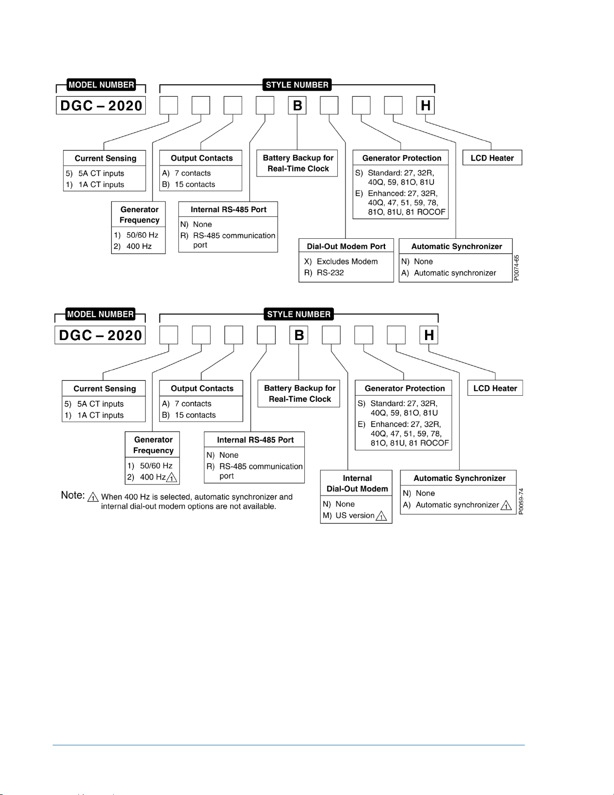
model number, together with the style number, describes the options included in a specific controller.
Figure 1-1 i llustrates the DGC-2020 styl e number identification ch art for hardware ver sion 3. Figure 1-2
illustrates the DGC-2020 style number identification chart for hardware versions 1 and 2.
Figure 1-1. DGC-2020 Style Chart for Hardware Version 3
Figure 1-2. DGC-2020 Style Chart for Hardware Versions 1 and 2
For example, if a DGC-2020 (hardw are version 3) style num ber were 51BNBREAH, the con troller would
have the following characteristics and operating features.
5 5 Aac current sensing inputs
1 50/60 hertz nominal generator frequency
B Three fixed-function output contacts and 12 programmable output contacts
N No RS-485 communication port
B Battery backup for real-time clock during losses of control power
R External dial-out modem port
E Enhanc ed gen er ator pr otection (27 undervoltage, 32R reverse power, 40Q loss of excitation, 47
phase imbalance, 51 overcurrent, 59 overvoltage, 78 vector shift, 81O overfrequency, 81U
underfrequency, and 81 ROCOF)
A Auto-synchronizer
H LCD heater
1-4 DGC-2020 General Information 9400200990 Rev X
Page 29

Specifications
Operating Power
Nominal ............................................. 12 or 24 Vdc
Range ............................................... 6 to 32 Vdc
Terminals .......................................... 3 (+), 2 (–), 1 (chassis ground)
Power Consumption
Sleep Mode ....................................... 5W with all relays non-energized
Normal Operational Mode ................ 7.9W - Run mode, LCD heater off, 3 relays energized
Maximum Operational Mod e ............ 14.2W - Run mode, LCD heater on, 6 relays energized
Battery Ride Through
Withstands cranking ride-through down to 0 V for 50 ms, starting at 10 Vdc.
Current Sensing
Burden .............................................. 1 VA
Terminals .......................................... 68, 69 (A-phase)
71, 72 (B-phase)
74, 75 (C-phase)
1 Aac Current Sensing
Continuous Rating ............................ 0.02 to 1.0 Aac
1 Second Rating ............................... 2 Aac
5 Aac Current Sensing
Continuous Rating ............................ 0.1 to 5.0 Aac
1 Second Rating ............................... 10 Aac
Voltage Sensing
Generator Configuration ................... Line-to-line or line-to-neutral
Bus Configuration ............................. Line-to-line
Range ............................................... 12 to 576 V rms, line-to-line
Frequency ......................................... Style selectable, 50/60 Hz or 400 Hz
Frequency Range ............................. 10 to 72 Hz for 50/60 style and 10 to 480 Hz for 400 Hz style
Burden ............................................. 1 VA
1 Second Rating ............................... 720 V rms
Generator Sensing Terminals ........... 41 (A-phase)
39 (B-phase)
37 (C-phase)
35 (Neutral)
Bus Sensing Terminals
Hardware Version 3 .......................... 76, 45 (A-phase)∗
78, 43 (B-phase)∗
80 (C-phase)
Hardware Versions 1 and 2 .............. 45 (A-phase)
43 (B-phase)
∗ In version 3 hardware, terminal 45 is internally tied to 76 and terminal 43 is internally tied to 78. This
accommodates the use of connectors wired for legacy DGC-2020 versions.
Contact Sensing
Contact sensing inputs incl ude 1 emergency stop input and 16 programmable inputs. All inputs accept dry
contacts.
Time from a DGC-2020 input application to:
Shutdown the generator via an alarm = 490 ms max
Close a relay on board the DGC-2020 = 215 ms max
Close a relay on board the CEM-2020 = 400 ms max
9400200990 Rev X DGC-2020 General Information 1-5
Page 30

A contact i nput is true (on) if the input is connected t o battery ground with a
resistance of less than 240 ohms.
The maximum length of wire that can be accommodated depends on the
resistance of the w ire, and the resist ance of the conta cts of the device driving
the input at the far end of the wire.
The maximum wire length can be calculated as follows:
L
= (240 – R
max
)/(Resistance per Foot of Desired Wire)
device
Terminals
Emergency Stop ............................... 46, 47
Programmable
Input 1 ............................................... 30, 2
Input 2 ............................................... 29, 2
Input 3 ............................................... 28, 2
Input 4 ............................................... 27, 2
Input 5 ............................................... 26, 2
Input 6 ............................................... 25, 2
Input 7 ............................................... 24, 2
Input 8 ............................................... 23, 2
Input 9 ............................................... 22, 2
Input 10 ............................................. 21, 2
Input 11 ............................................. 20, 2
Input 12 ............................................. 19, 2
Input 13 ............................................. 18, 2
Input 14 ............................................. 17, 2
Input 15 ............................................. 16, 2
Input 16 ............................................. 15, 2
NOTES
Engine System Inputs
Stated accuracies are subject to the accuracy of the senders used. Values within these ranges are
deemed “good” and the DGC-2020 will use them for the appropriate calculation and protection. Values
outside these ranges are deemed “bad” and the DGC-2020 will begin timing towards a sender failure
condition.
Fuel Level Sensing
Resistance Range ............................ 0 to 250 Ω nominal
Terminals .......................................... 9, 11 (sender common)
Coolant Temperature Sensing
Resistance Range ............................ 10 to 2,750 Ω nominal
Terminals .......................................... 10, 11 (sender common)
Oil Pressure Sensing
Resistance Range ............................ 0 to 250 Ω nominal
Terminals .......................................... 8, 11 (sender common)
Engine Speed Sensing
Magnetic Pickup
Voltage Range .................................. 3 to 35 V peak (6 to 70 V peak-peak)
Frequency Range ............................. 32 to 10,000 Hz
Terminals .......................................... 31 (+), 32 (–)
Generator Voltage
Range ............................................. 12 to 576 V rms
Terminals .......................................... 41 (A-phase)
39 (B-phase)
37 (C-phase)
1-6 DGC-2020 General Information 9400200990 Rev X
Page 31

Output Contacts
PRESTART, START, and RUN Relays
Rating ............................................... 30 Adc at 28 Vdc - General purpose, 3 A pilot duty∗
Programmable Relays (12)
Rating ............................................... 2 Adc at 28 Vdc - General purpose, 1.2 A pilot duty∗
∗ The load mus t be in parallel with a diode rated at least 3 tim es the coil current and 3 times the coil
voltage.
Terminals†
Output 1 ............................................ 52, 51 (common)
Output 2 ............................................ 53, 51 (common)
Output 3 ............................................ 54, 51 (common)
Output 4 ............................................ 56, 55 (common)
Output 5 ............................................ 57, 55 (common)
Output 6 ............................................ 58, 55 (common)
Output 7 ............................................ 60, 59 (common)
Output 8 ............................................ 61, 59 (common)
Output 9 ............................................ 62, 59 (common)
Output 10 .......................................... 64, 63 (common)
Output 11 .......................................... 65, 63 (common)
Output 12 .......................................... 66, 63 (common)
† The number of programmable output contacts provided is determined by the output contacts
character of the DGC-2020 style number. Controllers with output contacts option A have 4 programmable outputs (Outputs 1, 2, 3, and 4). Controllers with output contacts option B have 12
programmable outputs.
The programmable relays share common terminals: terminal 51 is used for outputs 1, 2, and 3,
terminal 55 is us ed for out puts 4, 5, and 6, ter minal 59 is used for outputs 7, 8, and 9, 63 is used for
outputs 10, 11, and 12.
Metering
Generator and Bus Voltage (rms)
Metering Range ................................ 0 to 576 Vac (direct measurement)
577 to 9,999 Vac (through VT using VT ratio setting)
VT Ratio Range ................................ 1:1 to 125:1 in primary increments of 1
Accuracy* ......................................... ±1.0% of programmed rated voltage or ±2 Vac
Display Resolution ............................ 1 Vac
* Voltage metering indicates 0 V when generator voltage is below 2% of the full-scale rating.
Generator Current (rms)
Generator current is measured at the secondary windings of user-supplied 1 A or 5 A CTs.
Metering Range ................................ 0 to 5,000 Aac
CT Primary Range ............................ 1 to 5,000 Aac in primary increments of 1 Aac
Accuracy* ......................................... ±1.0% of programmed rated current or ±2 Aac
Display Resolution ............................ 1 Aac
* Current metering indicates 0 A when generator current is below 2% of the full-scale rating.
Generator and Bus Frequency
Generator frequency is sensed through the generator voltage input.
Metering Range ................................ 10 to 72 Hz (50/60 Hz)
10 to 480 (400 Hz)
Accuracy ........................................... ±0.25% or 0.05 Hz
Display Resolution ............................ 0.1 Hz
Apparent Power
Indicates total kVA and individual line kVA (4-wire, line-to-neutral or 3-wire, line-to-line).
9400200990 Rev X DGC-2020 General Information 1-7
Page 32

Measurement/Calcula tio n Meth ods
Total .................................................. kVA = (V
× IL ×√3) ÷ 1000
L-L
4-Wire, Line-to-Neutral ..................... kVA calculated with respect to neutral
3-Wire, Line-to-Line .......................... A-phase kVA = V
B-phase kVA = V
C-phase kVA = V
× IA ÷ 1000 ÷ √3
AB
× IB ÷ 1000 ÷ √3
BC
× IC ÷ 1000 ÷ √3
CA
Accuracy ........................................... ±3% or the full-scale indication or ±2 kVA ∗†
∗ kVA metering indicates 0 kVA when the generator kVA is below 2% of the full-scale rating.
† Applies when temperature is between −40°C to +70°C.
Power Factor
Metering Range ................................ 0.2 leading to 0.2 lagging
Calculation Method ........................... PF = cosine of the angle between phase AB voltage (Vab) and
phase A current (Ia) *
Accuracy ........................................... ±0.02 †
* In single-phase AC-connected machines, it is the cosine of the angle between phase CA voltage
(Vca) and phase C current (Ic).
† Applies when temperature is between –40°C to +70°C (–40°F to +158°F).
NOTE
For the DGC-2020 to correctly meter power factor, the generator must be
rotating clockwise (A-B-C).
Real Power
Indicates total kW and individual line kW (4-wire, line-to-neutral or 3-wire line-to-line)
Measurement/Calcula tio n Meth ods
Total .................................................. PF × Total kVA
4-Wire, Line-to-Neutral ..................... kW calculated with respect to neutral
3-Wire, Line-to-Line .......................... A-phase kW = V
B-phase kW = V
C-phase kW = V
× IA × PF ÷ 1000 ÷ √3
AB
× IB × PF ÷ 1000 ÷ √3
BC
× IC × PF ÷ 1000 ÷ √3
CA
Accuracy ........................................... ±3% of the full-scale indication or ±2 kW ∗†
∗ kW metering indicates 0 kW when the generator kW is below 2% of the full-scale rating.
† Applies when temperature is between –40°C to +70°C.
Oil Pressure
Metering Range ................................ 0 to 150 psi, 0 to 10.3 bar, or 0 to 1,034 kPa
Accuracy ........................................... ±3% of actual indication or ±2 psi, ±0.12 bar, or ±12 kPa ( subjec t to
accuracy of sender)
Display Resolution ............................ 1 psi, 0.1 bar, or 1 kPa
Coolant Temperature
Metering Range ................................ 32 to 410°F or 0 to 204°C
Accuracy ........................................... ±3% of actual indication or ±2° (subject to accuracy of sender)
Battery Voltage
Metering Range ................................ 6 to 32 Vdc
Accuracy ........................................... ±3% of actual indication or ±0.2 Vdc
Display Resolution ............................ 0.1 Vdc
1-8 DGC-2020 General Information 9400200990 Rev X
Page 33

Engine RPM
Metering Range ................................ 0 to 4,500 rpm
Accuracy* ......................................... ±2% of actual indication or ±2 rpm
Display Resolution ............................ 2 rpm
* When engine speed is below 2% of full-scale, reported rpm is 0.
Engine Run Time
Engine run time is retained in nonvolatile memory.
Metering Range ................................ 0 to 99,999 hours
Update Interval ................................. 6 min
Accuracy ........................................... ±1% of actual indication or ±12 min
Display Resolution ............................ 1 minute
Maintenance Timer
Maintenance timer indicates the time remaining until genset service is due. Value is retained in
nonvolatile memory.
Metering Range ................................ 0 to 5,000 hours
Update Interval ................................. 6 min
Accuracy ........................................... ±1% or actual indication or ±12 min
Display Resolution ............................ 1 minute
Fuel Level
Metering Range ................................ 0 to 100%
Accuracy ........................................... ±2% (subject to accuracy of sender)
Display Resolution ............................ 1.0%
Generator Protection Functions
Overvoltage (59) and Undervoltage (27)
Pickup Range ................................... 70 to 1,000 Vac
Pickup Increment .............................. 1 Vac
Inhibit Frequency Range .................. 20 to 400 Hz (27 function only)
Activation Delay Range .................... 0 to 30 s
Activation Delay Increment ............... 0.1 s
NOTE
The maximum voltage that can be s afely ap plied to t he DGC-2020 is 576 volts.
The pickup range is higher so that when the lo w-line over ride is used, and the
scale factor is 0.5 or less, effective protection levels of 500 volts can be
reached with a scale factor of 0.5.
Underfrequency (81U) and Overfrequency (81O)
Pickup Range ................................... 45 to 66 Hz (50/60 Hz nominal)
360 to 440 Hz (400 Hz nominal)
Pickup Increment .............................. 0.1 Hz (50/60 Hz nominal)
0.1 Hz (400 Hz nominal)
Activation Delay Range .................... 0 to 30 s
Activation Delay Increment ............... 0.1 s
Inhibit Voltage Range ....................... 70 to 576 Vac (81U function only)
Reverse Power (32)
Pickup Range ................................... –50 to 5% of Genset kW Rating
Pickup Increment .............................. 0.1%
Hysteresis Range ............................. 1 to 10% of Genset kW Rating
Hysteresis Increment ........................ 0.1%
Activation Delay Range .................... 0 to 30 s
Activation Delay Increment ............... 0.1 s
9400200990 Rev X DGC-2020 General Information 1-9
Page 34

Loss of Excitation (40Q)
Pickup Range ................................... –150 to 0% of Rated kvar*
Pickup Increment .............................. 0.1%
Hysteresis Range ............................. 1 to 10% of Rated kvar*
Hysteresis Increment ........................ 0.1%
Activation Delay Range .................... 0 to 30 s
Activation Delay Increment ............... 0.1 s
* Rated kvar is calculated on the System Settings, Rated Data screen in BESTCOMSPlus®.
Overcurrent (51) (Optional)
Pickup Range ................................... 0.18 to 1.18 Aac (1 A current sensing)
0.9 to 7.75 Aac (5 A current sensing)
Time Dial Range ............................... 0 to 7,200 s (fixed time curve)
0 to 9.9 (inverse curve time multiplier)
Time Dial Increment.......................... 0.1
Inverse Time Curves......................... See Appendix A, Time Overcurrent Characteristic Curves
Phase Imbalance (47) (Optional)
Pickup Range ................................... 5 to 100 Vac
Pickup Increment .............................. 1 Vac
Activation Delay Range .................... 0 to 30 s
Activation Delay Increment ............... 0.1 s
ROCOF (Rate of Change of Frequency) (81) (Optional)
Pickup Range ................................... 0.2 to 10 Hz/s
Pickup Increment .............................. 0.1 Hz/s
Activation Delay Range .................... 0 to 100 s
Activation Delay Increment ............... 0.01 s
Vector Shift (78) (Optional)
Pickup Range ................................... 2 to 90°
Pickup Increment .............................. 1°
Logic Timers
Hours Setting Range ........................ 0 to 250
Hours Setting Increment ................... 1
Minutes Setting Range ..................... 0 to 250
Minutes Setting Increment ................ 1
Seconds Setting Range .................... 0 to 1,800
Seconds Setting Increment .............. 0.1
Accuracy ........................................... ±15 ms
Communication Interface
USB
Specification Compatibility ................ USB 2.0
Data Transfer Speed ........................ 115200 baud
Connector Type ................................ Mini-B jack
External Dial-Out Modem (Optional)
Protocol ............................................. ASCII
Data Transmission ............................ Full Dup lex
Baud ................................................. 9600
Data Bits ........................................... 8
Parity ................................................. None
Stop Bits ........................................... 1
Connector Type ................................ DB-9 Connector (Male)
RS-485 (Optional)
Baud ................................................. 9600
Data Bits ........................................... 8
1-10 DGC-2020 General Information 9400200990 Rev X
Page 35

Parity ................................................. None
The J1939 drain (shield) should be grounded at one point only. If
CAUTION
2020 is to be
Stop Bits ........................................... 1
Terminals .......................................... 14 (A), 13 (B), and 12 (shield)
RDP-110
Minimum Wire Size ........................... 20 AWG
Maximum Wire Length ...................... 4,000 feet ( 1,2 19 met er s)
Terminals .......................................... 6 (RDP TXD–), 7 (RDP TXD+)
CAN
NOTES
1. If the DGC-2020 is providing one end of the J19 39 bus, a 120 Ω, ½ watt
terminating resistor shou ld be insta lled ac ross terminal s 48 (CANL) and 49
(CANH).
2. If the DGC-2020 is not part of the J1939 bus, the stub connecting the
DGC-2020 to the bus should not exceed 914 mm (3 ft) in length.
3. The maximum bus length, not including stubs, is 40 m (131 ft).
4.
grounded elsewhere, do not connec t the drai n to the D GC -2020.
Differential Bus Voltage .................... 1.5 to 3 Vdc
Maximum Voltage ............................. –32 to +32 Vdc with respect to negative battery terminal
Communication Rate ........................ 250 kb/s
Terminals .......................................... 48 (low), 49 (high), and 50 (shield)
Real-Time Clock
Clock has leap year and s electable daylight s aving time cor rection. Backup c apacitor and backup battery
sustain timekeeping during losses of DGC-2 020 operating power.
Resolution ......................................... 1 s
Accuracy ........................................... ±1.73 s/d at 25°C
Clock Holdup
Battery Holdup Time ......................... Approximately 10 yrs
Battery Type ..................................... Rayovac BR2032, lithium, coin-type, 3 Vdc, 195 mAh
Basler Electric P/N 38526
Replacement of the bac kup bat tery f or the real-time clock s hould b e p er forme d
only by qualified personnel.
Do not short-circuit t he batt ery, rever se battery polarity , or attem pt to rechar ge
the battery. Observe po larity markings on the battery socket while inserting a
new battery. The battery polarity mus t be correc t in order to provide back up for
the real-time clock.
It is recommended that the battery be removed if the DGCoperated in a salt-fog environment. Salt-fog is known to be conductive and
may short-circuit the batter y.
NOTE
Failure to replace the battery with Basler Electric P/N 38526 may void the
warranty.
9400200990 Rev X DGC-2020 General Information 1-11
Page 36

LCD Heater
The ambient temperat ure is monitored by a temperat ure sensor located near the LCD ins ide the DGC-
2020. The LCD heater turns on when the ambient temperature falls below 0°C (32°F). The heater turns off
when the ambient temp erature rises above 5 °C (41°F). This range of operation implements 5°C (9°F) of
hysteresis between heater turn on and turn off.
Type Tests
Vibration ............................................ EN60068-2-6
Dielectric Strength ............................ EN60664-1
Impulse ............................................. EN60664-1
Transients ......................................... EN61000-4-4
Static Discharge ................................ EN61000-4-2
Shock
Withstands 15 G in 3 perpendicular planes.
Vibration
Swept over the following ra nges for 12 sweeps in e ach of three mutually per pendicular planes with each
15-minute sweep consisting of the following:
5 to 29 to 5 Hz .................................. 1.5 G peak for 5 minutes
29 to 52 to 29 Hz .............................. 0.036 inches (0.914 mm) double amplitude for 2.5 minutes
52 to 500 to 52 Hz ............................ 5 G peak for 7.5 minutes
Radio Interference
Type tested using a 5 W, hand-held transceiver operatin g at random frequencies centered ar ound 144
and 440 MHz with the antenna located within 150 mm ( 6”) of the device in both vertic al and horizontal
planes.
HALT (Highly Accelerated Life Testing)
HALT is used by Basler Electric to prove that our products will provide the user with many years of
reliable service. HALT subjects the device to extreme s in temperature, shock , and vibration to simulate
years of operation, but in a muc h s hort er period span. HALT a llo ws Basler Electric to evaluate all possib le
design elements that will add to the life of this device. As an example of some of the extreme testing
conditions, the DGC-2020 was subjected to temperature tests (tested over a temperature range of
–100°C to +115°C),
over a temperature range of –80°C to +90°C). Combined temperature and vibration testing at these
extremes proves that the D GC-2020 is ex pected to provide lon g-term oper ation in a r ugged envir onment.
Note that the vibration a nd t emperatur e ex tremes listed in this p aragra ph are s pec ific to H ALT and do not
reflect recommended operation levels. These operational ratings are included in Section 1 of this manual.
vibration tests (of 5 to 50 G at +20°C) , and temperature/vibration tests (tested at 40 G
Ignition System
Tested in close proximity to an unshielded, unsuppressed Altronic DISN 800 Ignition System.
Environment
Operating Temperature .................... –40 to +70°C (–40 to +158°F)
Storage Temperature........................ –40 to +85°C (–40 to +185°F)
Humidity ............................................ IEC 60068-2-38
Salt Fog ............................................ ASTM B 17-73, EN 68-2-11
Ingress Protection ............................. IEC IP54 for front panel
UL Recognition
The DGC-2020 is recognized to applicable Canadian and US safety standards and requirements by UL.
Standards used for evaluation:
• UL6200
• CSA C22.2 No. 14
CAUTION
To follow UL guidelines, replacement of the backup battery for the real-time
clock should be performed only by qualified personnel.
1-12 DGC-2020 General Information 9400200990 Rev X
Page 37

Part Number 9400200223
“cURus” recognized per Standard 1604, Electrical Eq uipment for Use in Class I and II, Div ision 2, a nd
Class III Hazardous (Classified) Locations, Class I, Division 2, Zone 2, Groups A, B, C, D,
Temperature Code - T3C.
This equipment is s uitable for use in Class I, Divis ion 2, Groups A, B, C, D, or n on-hazardous loc ations
only.
Currently, only style DGC-2020-51BRBXEAH is available with Hazardous Location certification. If an
additional style option is needed with this certification, contact Basler Elec tr ic.
WARNING! - EXPLOSION HAZARD
Substitution of components may impair suitability for Class I, Division 2.
Do not disconnect eq uipment unless power has been s witched off or the area
is known to be non-hazardous.
Exposure to some ch emicals may degrade the sealing proper ties of materials
used in the sealed relay device.
CSA Certification
The DGC-2020 was tested and has met the certification requirements for electrical, plumbing and/or
mechanical products.
Standards used for evalu ati on:
• CSA C22.2 No. 0
• CSA C22.2 No. 14
NFPA Compliance
Complies with NFPA Standard 110, Standard for Emergency and Standby Power.
CE Compliance
This product has been evaluated and complies with the relevant essential requirements set forth by the
EU legislation.
EC Directives:
• LVD – 2006/95/EC
• Electromagnetic Compatibility (EMC) – 2004/108/EC
Harmonized Standards used for evaluation:
• EN 50178: Electronic Equipment for use in Power Insta llatio ns
• EN 61000-6-4: Electromag netic Compatibility (EMC), Generic Sta ndards, Emission Standard for
Industrial Environments
• EN 61000-6-2: Electromag netic Compatibility (EMC), Generic Standards, Immunity for Industria l
Environments
GOST-R Certification
The DGC-2020 has been evaluated and complies with the relevant essential requirements set forth to
meet the Russian certification system.
Physical
Weight ............................................... 4.40 lb (1.99 kg)
Dimensions ....................................... See Section 6, Installation.
9400200990 Rev X DGC-2020 General Information 1-13
Page 38

1-14 DGC-2020 General Information 9400200990 Rev X
Page 39

SECTION 2 • HUMAN-MACHINE INTERFACE
TABLE OF CONTENTS
SECTION 2 • HUMAN-M ACHINE INTERF ACE ....................................................................................... 2-1
Introduction ............................................................................................................................................ 2-1
Front Panel ............................................................................................................................................. 2-1
Display Operation................................................................................................................................... 2-2
Login and Permissions ....................................................................................................................... 2-2
Summary Screen and Configurable Metering .................................................................................... 2-3
Sleep Mode ........................................................................................................................................ 2-4
Changing a Setting ............................................................................................................................. 2-4
Front Panel Display Structu r e ............................................................................................................ 2-4
Generator Network Status Dis pl ay ................................................................................................... 2-26
Rear Panel ........................................................................................................................................... 2-27
Figures
Figure 2-1. Front Panel HMI ...................................................................................................................... 2-1
Figure 2-2. Metering Screen Branc hes ..................................................................................................... 2-4
Figure 2-3. Settings Screen Branches..................................................................................................... 2-11
Figure 2-4. One-Line Diagram Menu Options (Available when One-Line Diagram is enabled) ............. 2-25
Figure 2-5. Breaker Hardware One-Line Diagram .................................................................................. 2-26
Figure 2-6. Rear Panel for DGC-2020 Hardware Version 3 .................................................................... 2-28
Figure 2-7. Rear Panel for DGC-2020 Hardware Versions 1 and 2. ....................................................... 2-30
Tables
Table 2-1. Front Panel HMI Descriptions .................................................................................................. 2-2
Table 2-2. Descriptions for Figure 2-6. Rear Panel for DGC-2020 Hardware Version 3. ....................... 2-29
Table 2-3. Descriptions for Figure 2-7. Rear Panel for DGC-2020 Hardware Versions 1 and 2. ........... 2-31
9400200990 Rev X DGC-2020 Human-Machine Interface i
Page 40

ii DGC-2020 Human-Machine Interface 9400200990 Rev X
Page 41

SECTION 2 • HUMAN-MACHINE INTERFACE
Introduction
This section describes the components of the DGC-2020 human-machine interface (HMI). DGC-2020
HMI components are located on the front panel (controls and indicators) and the rear panel (terminals and
connectors).
Front Panel
Figure 2-1 illustrates the front panel HMI of the DGC-2020. Table 2-1 lists the call-outs of Figure 2-1 along
with a description of each HMI component.
Figure 2-1. Front Panel HMI
9400200990 Rev X DGC-2020 Human-Machine Interface 2-1
Page 42

Table 2-1. Front Panel HMI Descriptions
Locator
Description
A
Liquid Crystal Display. The backlit, 64 by 128 pixel LCD serves as the local information
maintained at −40°C.
B
Not in Auto Indicator. This red LED lights when the DGC-2020 is not oper at ing in Auto
mode.
C
Alarm Indicator. This red LED lights continuously during alarm conditions and flashes
during pre-alarm conditions.
D
Supplying Load Indicator. This green LED lights when the generator current is greater
than EPS threshold current.
E
Alarm Silence Pushbutton. Pressing this button opens the relay output programmed as
the horn output.
F
Lamp Test Pushbutton. Pressing this button tests the DGC-2020 indicators by exercising
all LCD pixels and lighting all LEDs.
G
Auto Pushbutton and Mode Indicator. Pressing the Auto button places the DGC -2 020 in
Auto mode. The green Auto mode LED lights when Auto mode is active.
H
Off Pushbutton and Mode Indicator. Pressing this button places the DGC-2020 in Off
resets the Breaker Management Pre-Alarms and al l MTU ECU Alar ms .
I
Run Pushbutton and Mode Indicator. Pressing this button places the DGC-2020 in Run
mode. The green Run mode LED lights when Run mode is active.
J
Reset Pushbutton. This button is pressed to cancel a settings editing session and disc ard
Maintenance or Maintenance Due Pre-Alarm.
K
Arrow Pushbuttons. These four buttons are used to navigate through the front panel
lower the value of the selected setting.
L
Edit Pushbutton. Pressing this button starts an editing session and enables changes to
pressed again to save the setting changes.
source for metering, alarms, pre-alarms, and protective functions. Display operation is
mode. The red Off mode LED lights when the DGC-2020 is in Off mode. This button also
any settings changes. When pressed momentarily, this button also resets the Breaker
Management Pre-Alarms and all MTU ECU Alarms. This button is also used to reset the
Maintenance Interval when pressed for 10 seconds while viewing Hours Until
display menus and modify settings.
The left- and right-arrow buttons are used to navigate through the menu levels. The right-
arrow button is pressed to move downward through the menu levels and the left-arrow
button is pressed to move upward.
Within a level, the up-arrow and down-arrow buttons are used to move among items
within the menu level. Pressing the down-arrow button moves to items lower in the list.
Pressing the up-arrow button moves to items higher in the list.
During a settings editing session, the up- and down-arrow buttons are used to raise and
DGC-2020 settings. At the conclusion of an editing session, the Edit pushbutton is
Display Operation
The front panel display is us ed to make settings changes and display metering valu es. Refer to call-outs
J, K, and L in Table 2-1 for information on changing settings through the front panel and navigating
through the Metering screens.
Login and Permissions
Login
To login, navigate to the SETTINGS, ENTER PASSWORD screen and press the Edit key. Use the
Up/Down arrow keys to scroll through the characters. Use the Left/Right arrow keys to enter more
characters. Once the pass word has been entered, pres s the Edit key to login. A LOGO UT selection now
2-2 DGC-2020 Human-Machine Interface 9400200990 Rev X
Page 43

appears in the list of SETTING S. To logout, navigate to SETTING S > LOGOUT and press the Edit key.
• VOLT∗
Hz
• OIL
BATT
• NONE (Removes a line from the scrolling list)
GEN IB
• RTD IN X (X = 1 to 8) (with AEM-2020)
DEF 1 %
The LOGOUT selection is removed from the SETTINGS list.
If a front-panel key is not pressed for more than 15 minutes, the user is automatically logged out.
Permissions
If communications access is active through the modem or USB, the front panel will display REMOTE
COMMS, FRONT PANEL IS RE AD ONLY and the summary sc reen. This informs the user that the front
panel can only be used for viewing metering data and settings information. Remote access must be
ended before modifying settings through the front panel.
Summary Screen and Configurable Metering
The summary screen can be set to standard or scrolling. When set to standard, only the follow ing are
displayed:
• AMP∗
• PH∗
•
∗ When s et to standard, individual phas e information can be automatically t oggled at a rate set by the
Phase Toggle Delay settin g. Navigate to the SETTIN GS > G ENERAL SETT INGS > FRONT PANEL HMI
screen and edit PH TOG DELAY. When the Phase Toggle Delay is set to zero, information for each
phase is obtained by pressing the Up or Down arro w keys on the front panel HMI . When it is set to a
number other than zero, th e display will toggle thr ough the phases automat ically at the rate specif ied by
the Phase Toggle Delay Setting.
† When a Selective Catalytic Reduction (SCR) with Diesel Exhaust Fluid (DEF) exhaust after-treatment
system is implemented, the Summary screen automatically alternates the display of FUEL level and DEF
level.
When the summary screen is set to scrolling, you can select/configure the metering values that are
displayed. Up to 20 v alues can be d isplayed and thes e values will sc roll at a delay tim e specified by the
user. To select a stan dard or scrolling summar y, navigate to the S ETTINGS > GENER AL SETTINGS >
FRONT PANEL HMI screen and edit the SUMMARY VIEW. The SCROLL DELAY setting is also found on
this screen.
To select the scrolling val u es , nav ig ate to t he S ETT IN G S > GENERAL S ETT IN GS > FRONT PANEL HMI
screen and edit the CO NFIGURABLE METERING. The following items may be selecte d by th e us er to be
placed in the scrolling summary:
• BLANK (Shows nothing on this line)
• OIL P
• TEMP
• BATT V
• RPM
• RPM SRC
• FUEL
• RUN HRS
• GEN VAB
• GEN VBC
• GEN VCA
• GEN VAN
• GEN VBN
• GEN VCN
• BUS Hz
• BUS V
• GEN Hz
• GEN PF
• kWH
• GEN IA
•
• FUEL/DEF†
• TEMP
•
• THRM CPL X (X = 1 to 2) (with AEM-2020)
• FUEL DELV P
• kvar A
• kvar B
• kvar C
• kvar TOTAL
• INJ RAIL PRS
• TOTAL FUEL USED
• FUEL TEMP
• ENG OIL TEMP
• ENG INTCLR TEMP
• COOLANT PRESS
• FUEL RATE
• BOOST PRESS
• INTAK MNFLD TMP
• CHRG AIR TMP
• ENGINE % LOAD
• BUS VAB
• BUS VBC
• BUS VCA
•
9400200990 Rev X DGC-2020 Human-Machine Interface 2-3
Page 44

• GEN IC
• kW A
ALG IN X (X = 1 to 8) (with AEM-2020)
• DEF 2 %
G
L
P0059-83
ENGINE
GENERATOR
POWER
BIAS CONTROL (Available when LSM-2020 is enabled.)
RUN STATISTICS
ALARMS-STATUS
DIAGNOSTICS
METERING
• kW B
• kW C
• kW TOT
• kVA A
• kVA B
• kVA C
• kVA TOT
• KW LD%
• ON LINE
• # UNITS
• SYS CAP
• SYS KW
• SY KVAR
• SYS TOTAL KW
• SYS GEN KW %
•
Sleep Mode
Sleep mode serves as a power sav ing featur e. If the DGC-2020 is in Off m ode or Auto mode n ot running
and a key is not press ed for more than 15 minutes, t he front panel LCD backlight an d LCD heater are
turned off. The DGC-2020 res umes normal display operation when any front panel button is pressed or
the genset is starte d remotely via the ATS input. T he DGC-2020 will not go to sleep while in an Alarm
state. If needed, Sleep mode can be permanently disabled via BESTCOMSPlus® or the front panel.
Changing a Setting
To change a setting, navigate to the setting you want to change and press the Edit key. If yo u are not
already logged in, you wi ll be as ked t o e nter y our password at this time. Us e the Up/Down arrows to raise
or lower the value. Press the Edit key again when finished.
Front Panel Display Structure
The front panel display begins with the SU MMARY SCREE N. Pressing the Right arrow key will open t he
MAIN MENU screen. The MAIN M ENU screen consists of MET ERING, SETTINGS, and, when enabled,
the ONE-LINE DIAGRAM, indicated by this symbol: The METERING screen branches are
shown in Figure 2-2. Details of the METERING screen branches follow Figure 2-2. The SETTINGS
screen branches are show n in Figure 2-3. Details of t he SETTINGS screen branches follow Figure 2-3.
The ONE-LINE DIAGRAM s c reen options are shown in Figure 2-4.
Figure 2-2. Metering Screen Branc hes
ENGINE
● OIL PRESSURE
● COOLANT TMP
● BATTERY VOLT
● RPM
● SPEED SRC
● FUEL LEVEL
● ENGINE LOAD
● COOLANT LEVL (Visible when CAN BUS is enabled.)
● TOTAL RUN TM
● HRS TO MAINT
● DEF TANK 1 LVL %
● DEF TANK 2 LVL %
2-4 DGC-2020 Human-Machine Interface 9400200990 Rev X
Page 45

GENERATOR
● GEN CONNECT
● GEN VAB
● GEN VBC
● GEN VCA
● GEN VAN
● GEN VBN
● GEN VCN
● GEN FREQ
● GEN AMPS A
● GEN AMPS B
● GEN AMPS C
● BUS CONNECT
● BUS VAB
● BUS VBC (Visible when three-phase bus connection is selected.)
● BUS VCA (Visible when three-phase bus connection is selected.)
● BUS FREQ
● SYNCHRONIZER
○ SLIP ANGLE
○ DELTA HERTZ
○ DELTA VOLTS
○ STATUS
● MAX VECT SHIFT (Optional)
● MAX ROCOF (Optional)
● ROCOF (Optional)
POWER
● kW A
● kW B
● kW C
● kW TOTAL
● kVA A
● kVA B
● kVA C
● kVA TOTAL
● kvar A
● kvar B
● kvar C
● kvar TOTAL
● PF
BIAS CONTROL (Visible when LS M-2020 is enabled.)
● var MODE
● PF MODE
● BL LV SRC
● BASELOAD LVL
● kvar SRC
● kvar SETPT
● PF SRC
● PF SETPT
RUN STATISTICS
● CUMULATIVE
○ CUMULATIVE
■ START
■ # STARTS
■ HRS TO MAINT
■ kW-HRS
○ TOTAL RUN TIME
■ HOURS
■ MINUTES
9400200990 Rev X DGC-2020 Human-Machine Interface 2-5
Page 46

○ LOADED RUN TIME
■ HOURS
■ MINUTES
○ UNLOADED RUN TIME
■ HOURS
■ MINUTES
● SESSION
○ SESSION
■ START
■ kW-HRS
○ TOTAL RUN TIME
■ HOURS
■ MINUTES
○ LOADED RUN TIME
■ HOURS
■ MINUTES
○ UNLOADED RUN TIME
■ HOURS
■ MINUTES
ALARMS-STATUS
● ACTIVE ALARMS
● ACTIVE PRE-ALARMS
● MTU FAULT CODES (Visible when ECU is configured for MTU MDEC, MTU ADEC, or MTU ECU7/ECU8.)
● MTU STATUS (Visible when ECU is configured for MTU MDEC, MTU ADEC, MTU ECU7/ECU8, or MTU Smart
Connect.)
○ NMT-ALIVE STATUS (Visible when ECU is configured for MTU MDEC or MTU ECU7/ECU8.)
■ SPS NODE
■ SW TYP
■ SW VAR
■ SW ED1
■ SW ED2
■ REV
■ SW MOD
○ TRIP FUEL (Visible when ECU is configured for MTU ECU7/ECU8.)
■ TRIP HRS
■ TRIP IDLE HRS
■ FUEL RATE
■ TRIP FL RATE
■ TOTAL RUN TM
■ DAILY FUEL
■ TOTAL FUEL
○ FUEL (Visible when ECU is configured for MTU ADEC.)
■ DAY TANK LVL
■ STORE TANK LVL
○ ENGINE STATUS (Visible when ECU is configured for MTU ADEC, MTU ECU7/ECU8, or MTU Smart
Connect.)
■ MTU FAULT CODES
■ ENG RUNNING
■ CYL CUTOUT
■ ENG OPTIMIZED (Visible when ECU is configured for MTU ADEC or MTU ECU7/ECU8.)
■ PREHT NT RCHD (Visible when ECU is configured for MTU ADEC or MTU ECU7/ECU8.)
■ SPEC TORQUE (Visible when ECU is configured for MTU ADEC or MTU ECU7/ECU8.)
■ SPD DMD FL MD (Visible when ECU is configured for MTU ADEC.)
■ CURR P DEGREE (Visible when ECU is configured for MTU ADEC.)
■ LOAD GEN ON (Visible when ECU is configured for MTU ADEC, MTU ECU7/ECU8, or MTU
Smart Connect.)
■ PRIME PUMP ON (Visible when ECU is configured for MTU ADEC.)
■ RUNUP SPD LO (Visible when ECU is configured for MTU ADEC.)
■ IDLE SPD LO (Visible when ECU is configured for MTU ADEC.)
■ CYL CUTOUT CD (Visible when ECU is configured for MTU ECU7/ECU8.)
■ RPM (Visible when ECU is configured for MTU ECU7/ECU8.)
■ DROOP % (Visible when ECU is configured for MTU ECU7/ECU8 or MTU Smart Connect.)
■ ENG COOL TEMP (Visible when ECU is configured for MTU ECU7/ECU8.)
■ CHRG AIR TMP (Visible when ECU is configured for MTU ECU7/ECU8.)
■ INTRCOOLR TEMP (Visible when ECU is configured for MTU ECU7/ECU8.)
2-6 DGC-2020 Human-Machine Interface 9400200990 Rev X
Page 47

■ ENG OIL TEMP (Visible when ECU is configured for MTU ECU7/ECU8.)
■ FUEL TEMP (Visible when ECU is configured for MTU ECU7/ECU8.)
■ ECU TEMP (Visible when ECU is configured for MTU ECU7/ECU8.)
■ OIL PRESSURE (Visible when ECU is configured for MTU ECU7/ECU8.)
■ CHG AIR P (Visible when ECU is configured for MTU ECU7/ECU8.)
■ FUEL DELV P (Visible when ECU is configured for MTU ECU7/ECU8.)
■ FL RAIL P (Visible when ECU is configured for MTU ECU7/ECU8.)
■ CAMSHAFT RPM (Visible when ECU is configured for MTU ECU7/ECU8.)
■ IDLE RPM (Visible when ECU is configured for MTU ECU7/ECU8.)
■ ECU SHUTDOWN (Visible when ECU is configured for MTU ECU7/ECU8.)
■ TOTAL RUN TM (Visible when ECU is configured for MTU ECU7/ECU8.)
■ ECU SUPP VOLTS (Visible when ECU is configured for MTU ECU7/ECU8.)
■ INJCT DBR % (Visible when ECU is configured for MTU ECU7/ECU8.)
■ RATED RPM (Visible when ECU is configured for MTU ECU7/ECU8.)
■ INJCT QTY (Visible when ECU is configured for MTU ECU7/ECU8.)
■ RATED KW (Visible when ECU is configured for MTU ECU7/ECU8.)
■ RESRV PWR % (Visible when ECU is configured for MTU ECU7/ECU8.)
■ START SEQ (Visible when ECU is configured for MTU ECU7/ECU8 or MTU Smart Connect.)
■ ECU OVRD FDBK (Visible when ECU is configured for MTU Smart Connect.)
■ COOLNT PRHT DONE (Visible when ECU is configured for MTU Smart Connect.)
■ REQ TORQUE (Visible when ECU is configured for MTU Smart Connect.)
■ EXT STOP (Visible when ECU is configured for MTU Smart Connect.)
■ OPERATING MODE (Visible when ECU is configured for MTU Smart Connect.)
○ SPEED (Visible when ECU is configured for MTU ADEC, MTU ECU7/ECU8, or MTU Smart Connect.)
■ SEL SPD DMD
■ EFF SET SPEED
■ CAN SPD DMD
■ ANLG SPD DMD
■ SPD DMD FL MD
■ RATED RPM (Visible when ECU is configured for MTU ECU7/ECU8.)
■ RPM (Visible when ECU is configured for MTU ECU7/ECU8.)
■ CAMSHAFT RPM (Visible when ECU is configured for MTU ECU7/ECU8.)
■ IDLE RPM (Visible when ECU is configured for MTU ECU7/ECU8.)
■ SPD DMD SRC (Visible when ECU is configured for MTU ECU7/ECU8.)
■ FREQ RPM DMD (Visible when ECU is configured for MTU ECU7/ECU8.)
○ SIGNL FEEDBK (Visible when ECU is configured for MTU ADEC, MTU ECU7/ECU8, or MTU Smart
Connect.)
■ ECU_OVRD_FDBK
■ EXT STOP
■ SPD UP IN
■ SPD DN IN
■ CAN MODE FDBK
■ CYL CUTOUT (Visible when ECU is configured for MTU ECU7/ECU8.)
○ DIAGNOSTICS (Visible when ECU is configured for MTU ECU7/ECU8.)
■ AL PWR AMP 1
■ AL PWR AMP 2
■ XSTR OUT AL
■ XSTR OUT STS
■ ECU SHUTDOWN
○ CAN Bus (Visible when ECU is configured for MTU ECU7/ECU8.)
■ CAN MODE FDBK
■ CAN NODES
■ LOST NODES
○ LIMITS (Visible when ECU is configured for MTU ECU7/ECU8.)
■ OIL PRESSURE
■ LO LIM OILP
■ LOLOLIM OILP
■ ENG COOL TEMP
■ CLNT LMT HI
■ CLNT LMT HIHI
■ CHRG AIR TMP
■ CHG AIR LMT HI
■ ECU SUPP VOLTS
■ L1L ECU VOLTS
■ L2L ECU VOLTS
■ U1L ECU VOLTS
■ U2l ECU VOLTS
9400200990 Rev X DGC-2020 Human-Machine Interface 2-7
Page 48

■ INTRCOOLR TMP
■ INTCLR LMT HI
● STATUS
○ AUTO XFER SWITCH (Visible when the Auto Transfer Switch programmable function is configured to
be driven by an input.)
○ EPS SUPP. LOAD
○ GEN BREAKER
○ MAINS BREAKER
○ BATTLE OVERRIDE (Visible when the Battle Override programmable function is configured to be
driven by an input.)
○ LOW LINE OVERRIDE (Visible when the Low Line Override programmable function is configured to be
driven by an input.)
○ LOW COOL LEVEL (Visible when the Low Coolant Level programmable function is configured to be
driven by an input.)
○ BATT CHRG FAIL (Visible when the Battery Charger Fail programmable function is configured to be
driven by an input.)
○ FUEL LEAK DETECT (Visible when the Fuel Leak Detect programmable function is configured to be
driven by an input.)
○ GRND DELTA O-RIDE (Visible when Generator Connection is configured for Delta and the Grounded
Delta Override programmable function is configured to be driven by an input.)
○ 1 PHASE O-RIDE (Visible when the 1-Phase Override programmable function is configured to be driven
by an input.)
○ 1 PHASE AC O-RIDE (Visible when the 1-Phase AC Override programmable function is configured to
be driven by an input.)
○ BUS DEAD
○ BUS STABLE
○ BUS FAILED
○ BUS FWD ROT
○ BUS REV ROT
○ GEN DEAD
○ GEN STABLE
○ GEN FAILED
○ GEN FWD ROT
○ GEN REV ROT
○ ENG RUNNING
○ CLDN TMR ACTVE
○ OFF MODE COOLDN
○ COOLDN REQ
○ COOL & STOP REQ
○ var MODE
○ PF MODE
○ EXT START DEL
○ START DEL BYPASS
○ ALT FRQ O-RIDE
○ RESET
○ ALARM SILENCE
○ LAMP TEST
○ IDLE REQUEST
○ LOAD TAKEOVER
○ MAINS FAIL TEST
○ SYNCHRONIZING
○ SYNC VOLT OK
○ SYNC SLIP FRQ OK
○ SYNC ANGLE OK
○ SYNC BRK CL OK
○ PARALLEL TO MAINS
○ LSM CONNECTED
○ CEM CONNECTED
○ AEM CONNECTED
● INPUTS
○ INPUT X (X = 1 to 16 (17 to 26 optional))
● OUTPUTS
○ START
○ RUN
○ PRESTART
○ OUTPUT X (X = 1 to 12 (13 to 36 optional))
2-8 DGC-2020 Human-Machine Interface 9400200990 Rev X
Page 49

● LOGIC CTL RELAYS
○ LCR X (X = 1 to 16)
● LSM INPUTS (Visible when LSM-2020 is enabled.)
○ SCALED
○ RAW
■ LSM IN
● ANALOG INPUTS (Visible when AEM-2020 is enabled.)
○ SCALED
■ ALG IN X (X = 1 to 8)
○ RAW
■ ALG IN X (X = 1 to 8)
● THERMAL INPUTS (Visible when AEM-2020 is enabled.)
○ SCALED
■ RTD IN X (X = 1 to 8)
■ THRM CPL X (X = 1 to 2)
○ RAW
■ RTD IN X (X = 1 to 8)
■ THRM CPL X (X = 1 to 2)
● ANALOG OUTPUTS (Visible when AEM-2020 is enabled.)
○ SCALED
■ ALG OUT X (X = 1 to 4)
○ RAW
■ ALG OUT X (X = 1 to 4)
● ANALOG STATUS (Visible when AEM-2020 is enabled.)
● CONF ELEMENTS
○ CONFIG ELEMENT X (X = 1 to 8)
● CONF PROT STATUS
● EVENT LOG
○ [EVENT NAME]
■ ACTIVE
■ OCCURRENCE COUNT
■ FIRST DATE
■ FIRST TIME
■ LAST DATE
■ LAST TIME
■ FIRST ENG HRS
■ LAST ENG HRS
■ DETAILS
□ OCCURRENCE (Use the Edit/Up/Down keys to change the occurrence.)
□ DATE
□ TIME
□ ENG HRS
■ CLEAR EVENT (Visible when logged in through the front panel.)
● J1939 DATA (Visible when CAN bus is enabled and ECU is configured for Standard, Volvo Penta, MTU ADEC,
GM/Doosan, Cummins, Scania, or John Deere.)
○ THROTTLE POSITN
○ LOAD @ CRNT RPM
○ ACTUAL ENG TORQ
○ ENGINE SPEED
○ INJ CNTRL PRESS
○ INJ RAIL PRS
○ ENGINE HOURS
○ TRIP FUEL
○ TOTAL FUEL USED
○ ENG COOLANT TEMP
○ FUEL TEMP
○ ENG OIL TEMP
○ ENG INTCLR TEMP
○ FUEL DELV P
○ ENG OIL LEVEL
○ ENG OIL PRESS
○ COOLANT PRESS
○ COOLANT LEVEL
○ FUEL RATE
○ BAROMETRIC PRESS
○ AMB AIR TEMP
○ AIR INLET TEMP
9400200990 Rev X DGC-2020 Human-Machine Interface 2-9
Page 50

○ BOOST PRESS
○ INTAK MNFLD TEMP
○ AIR FLTR DIF PRS
○ EXHAUST GAS TEMP
○ BATTERY VOLTAGE
○ ECU INPUT VOLTS
○ TRANS OIL PRESS
○ TRANS OIL TEMP
○ WINDG 1 TEMP
○ WINDG 2 TEMP
○ WINDG 3 TEMP
○ ECU TEMP
○ AUX PRESSURE1
○ AUX PRESSURE2
○ RATED KW
○ RATED RPM
○ EXHAUST TMP A
○ EXHAUST TMP B
○ CHRG AIR TMP
○ FUEL 1 LEAK
○ FUEL 2 LEAK
○ ALARM RST FDBK
○ ECU SHUTDOWN
○ DEF TANK 1 LVL %
○ DEF TANK 2 LVL %
● J1939 ENGINE CONFIG (Visible when ECU is configured for Standard, Volvo Penta, MTU ADEC, GM/Doosan,
or Cummins.)
○ SPD @ IDLE PNT 1
○ TRQ @ IDLE PNT 1
○ SPD @ PNT 2
○ TRQ @ PNT 2
○ SPD @ PNT 3
○ TRQ @ PNT 3
○ SPD @ PNT 4
○ TRQ @ PNT 4
○ SPD @ PNT 5
○ TRQ @ PNT 5
○ SPD @ PNT 6
○ ENDSPEED GOV KP
○ REF ENG TORQUE
○ O-RIDE SPD PNT 7
○ O-RIDE TIME LMT
○ SPEED LOWER LMT
○ SPEED UPPER LMT
○ TORQUE LOWER LMT
○ TORQUE UPPER LMT
● J1939 ACTIVE DTC (Visible when D TC supp or t is enab led a nd any ECU type is sel ect ed.)
○ CLEAR DTCs
● J1939 PREV DTC (Visible when DTC support is enabled and any ECU type is selected.)
○ CLEAR DTCs
● NETWORK STATUS (Visible when Multiple Generator is selected as System Type.)
○ SYSTEM MANAGER (Displays “0” when LSM-2020 is not connected.)
○ NUMBER OF UNITS (Displays “0” when LSM-2020 is not connected.)
○ ID (Visible when LSM-2020 is connected.)
○ NUM ON LINE (Displays “0” when LSM-2020 is not connecte d.)
○ ID X (X = 1 to 16) (The ID of each online unit is displayed)
○ SYS KW CAP
○ SYS GEN KW
○ SYS GEN KVAR
● SEQUENCING STATUS (Visible when Demand Start/Stop is enabled.)
○ NEXT TO START (Displays “0” when LSM-2020 is not connected.)
○ NEXT TO STOP (Displays “0” when LSM-2020 is not connected.)
○ START TMR 1
○ START TMR 2
○ STOP TIMER
○ WATT DEMAND
○ MODE
2-10 DGC-2020 Human-Machine Interface 9400200990 Rev X
Page 51

○ SEQUENCE ID (Displays “0” when LSM-2020 is not connected.)
P0059-82
GENERAL SETTINGS
COMMUNICATIONS
SYSTEM PARAMS
PROGRAMMABLE INPUTS
PROGRAMMABLE OUTPUTS
CONFIG PROTECTION
ALARM CONFIGURATION
GENERATOR PROTECTION
BREAKER MANAGEMENT
BIAS CONTROL
MULTIGEN MANAGEMENT (Available when LSM-2020 is enabled.)
LOGIC TIMERS
ENTER PASSWORD
SETTINGS
○ SYSTEM MANAGER (Displays “0” when LSM-2020 is not connec ted.)
○ START LVL 1
○ START LVL 2
○ STOP LVL
○ START TD 1
○ START TD 2
○ STOP TD
● MAINS FAIL TRANSFER (Visible when Mains Fail Transfer is enabled.)
○ MAINSFAIL XFER STATE
■ DISABLED ( The possible mains fail transfer states are as follows: Power From Mains,
Transfer Timer Active, Transferring to Gens, Power From Gens, Return Timer Active,
Transferring to Mains, Disabled (when DGC is in OFF or RUN modes, or in the alarm state))
○ TRANSFER DELAY (Visible when actively counting and relevant to mains fail transfer.)
○ RETURN DELAY (Visible when actively counting and relevant to mains fail transfer.)
○ MAX TRANSFER TIME (Visible when actively counting and relevant to mains fail transfer.)
○ MAX PARALLEL TIME (Visible when actively counting and relevant to mains fail transfer.)
○ OPEN TRANS DELAY (Visible when actively counting and relevant to mains fail transfer.)
DIAGNOSTICS
● MODBUS RD
● MODBUS WR
● FLASH WR
Figure 2-3. Settings Screen Branches
GENERAL SETTINGS
● FRONT PANEL HMI
● CONFIGURE DATE/TIME
9400200990 Rev X DGC-2020 Human-Machine Interface 2-11
○ SUMMARY VIEW
○ SCROLL DELAY
○ PH TOG DELAY
○ LCD CONTRAST
○ SLEEP MODE
○ LANGUAGE
○ CONFIGURABLE METERING
■ ITEM X (X = 1 to 20)
○ ONE-LINE DIAGRAM
○ YEAR
○ MONTH
○ DAY
○ HOURS
Page 52

○ MINUTES
○ SECONDS
○ UTC OFFSET
○ DST ENABLED
○ CLK NOT SET WRN
● VIEW DATE/TIME
● VERSION INFO
○ DGC-2020
■ FIRMWARE VERSION
■ BOOT CODE VERSION
■ SERIAL NUMBER
■ PART NUMBER
■ MODEL NUMBER
■ LANGUAGE VERSION
■ LANGUAGE PART NUM
■ STYLE CODE
○ LSM-2020 (Visible when LSM-2020 is enabled.)
■ VERSION INFO
■ TCP/IP SETTINGS
○ CEM-2020 (Visi ble when CEM-2020 is enabled.)
■ FIRMWARE VERSION
■ BOOT CODE VERSION
■ SERIAL NUMBER
■ PART NUMBER
■ MODEL NUMBER
■ BUILD DATE
○ AEM-2020 (Visible when AEM-2020 is enabled.)
■ FIRMWARE VERSION
■ BOOT CODE VERSION
■ SERIAL NUMBER
■ PART NUMBER
■ MODEL NUMBER
■ BUILD DATE
□ FIRMWARE VERSION
□ BOOT CODE VERSION
□ IP ADDRESS
□ SUBNET MASK
□ GATEWAY ADDRESS
□ DHCP ENABLE
● CAN Bus SETUP
○ CAN Bus SETUP
■ CAN Bus ENABLE
■ DTC ENABLE (Visible when CAN bus is enabled.)
■ SPN CONV METHOD (Visib le when CAN bus is enabled.)
■ CAN Bus ADDR (Visible when CAN bus is enabled.)
■ ECU OPT SLCT (Visible when CAN bus is enabled.)
■ ECU PULSING (Visible when CAN bus is enabled.)
■ ENG SHTDN TM (Visible when CAN bus is enabled.)
■ PLS CYCL TM (Visible when CAN bus is enabled.)
■ ECU SET TM (Visible when CAN bus is enabled. )
■ RESP TIMEOUT (Visible when CAN bus is enabled.)
○ ECU SETUP (Visible when CAN bus is enabled.)
■ ECU CONF
■ GEN DATA TRANSMIT (Visible when ECU is configured for Standard, Volvo Penta, MTU
■ ENGINE PARAM XMT
■ TRIP RESET (Visible when ECU is configured for Standard, Volvo Penta, MTU ADEC,
■ DPF REGENRATE SETUP (Visible when ECU is configured for Standard, Volvo Penta, MTU
■ SPEED SELECT (Visible when ECU is configured for Volvo Penta.)
■ ACCEL POSITION (Visible when ECU is configured for Volvo Penta.)
COMMUNICATIONS
ADEC, GM/Doosan, Cummins, or MTU Smart Connect.)
GM/Doosan, Cummins, or MTU Smart Connect.)
ADEC, GM/Doosan, Cummins, or MTU Smart Connect.)
□ DPF MANUAL REGEN
□ DPF REGEN DISABLE
2-12 DGC-2020 Human-Machine Interface 9400200990 Rev X
Page 53

■ MODULE TYPE (Visible when ECU is configured for MTU MDEC or MTU ECU7/ECU8.)
■ ALIVE MSG (Visible when ECU is configured for MTU MDEC or MTU ECU7/ECU8.)
■ SPEED SETUP (Visible when ECU is configured for (MTU ADEC, MTU MDEC 304, MTU
■ ECU SETUP (Visible when ECU is configured for MTU ADEC, MTU ECU7/ECU8, or MTU
● MODEM SETUP
○ DIALOUT X (X = 1 TO 4)
○ PAGER ID X (X = 1 TO 4)
○ RINGS FOR ANSWER
○ OFFLN DELAY
○ DIALOUT DLY
○ PGR BUFF LMT
○ PGR COM
● RS485 SETUP
○ COMM BAUD
○ COMM PARITY
○ MODBUS ADDR
○ LEGACY MODBUS
ECU7/ECU8, or MTU Smart Connect.)
□ J1939 RPM ENABLE (Visible when ECU is configured for Standard, Volvo Penta,
MTU ADEC, GM/Doosan, Cummins, or MTU Smart Connect.)
□ ENGINE RPM
□ RPM BAND WIDTH
□ IDLE RPM
□ SPEED UP (Visible when ECU is configured for MTU ADEC, MTU MDEC 304, MTU
ECU7/ECU8, or MTU Smart Connect.)
□ SPEED DN (Visible when ECU is configured for MTU ADEC, MTU MDEC 304, MTU
ECU7/ECU8, or MTU Smart Connect.)
□ TEST OVRSPEED (Visible when ECU is configured for MTU ADEC, MTU MDEC
304, MTU ECU7/ECU8, or MTU Smart Connect.)
□ SPD DMAND SRC (Visible when ECU is configured for MTU MDEC 304, MTU
ECU7/ECU8, or MTU Smart Connect.)
□ IDLE REQUEST (Visible when ECU is configured for MTU MDEC 304, MTU
ECU7/ECU8, or MTU Smart Connect.)
□ INCREASE IDLE (Visible when ECU is configured for MTU MDEC 304, or MTU
ECU7/ECU8.)
Smart Connect.)
□ TRIP RESET (Visible when ECU is configured for MTU ECU7/ECU8.)
□ INT OIL PRIME
□ GOV PRM SW (Visible when ECU is configured for MTU ADEC or MTU Smart
Connect.)
□ ENG STRT PRIME (Visible when ECU is configured for MTU ECU7/ECU8.)
□ FAN OVERRIDE (Visible when ECU is configured for MTU ECU7/ECU8.)
□ MODE SWITCH (Visible when ECU is configured for MTU ECU7/ECU8.)
□ GOV PARAM SET (Visible when ECU is configured for MTU ECU7/ECU8.)
□ CAN RATING SW 1 (Visible when ECU is configured for MTU ECU7/ECU8.)
□ CAN RATING SW 2 (Visible when ECU is configured for MTU ECU7/ECU8.)
□ DIS CYL CUT 1 (Visible when ECU is configured for MTU ECU7/ECU8.)
□ DIS CYL CUT 2 (Visible when ECU is configured for MTU ECU7/ECU8 or MTU Smart
Connect.)
□ OPERATING MODE (Visible when ECU is configured for MTU Smart Connect.)
SYSTEM PARAMS
● SYSTEM SETTINGS
○ GEN CONNECT
○ BUS CONNECT
○ RATED kW
○ RATED VOLTS
○ RATED FREQ
○ ALTRNATE FRQ
○ RATED RPM
○ RATED PF
○ ROTATION
○ SYSTEM TYPE
9400200990 Rev X DGC-2020 Human-Machine Interface 2-13
Page 54

○ EPS
■ EPS THRESHLD
■ LOW LINE SF (Visible when an input is selected for the Low Line Override programmable
function.)
○ FUEL LEVEL SETUP
■ FUEL LVL TYP
■ FUEL LVL SRC (Visible when AEM-2020 is enabled)
■ FL MAX ALG % (Visible when AEM-2020 is enabled)
■ FL MIN ALG % (Visible when AEM-2020 is enabled)
○ SYSTEM UNITS
○ PRESSURE UNITS (Visible when Metric is selected for System Units.)
○ BATTERY VOLT
○ FLYWHL TEETH
○ SPEED SOURCE
○ MAINT RESET
○ NFPA LEVEL
○ POWER UP DELAY
● REMOTE MODULE SETUP
○ LSM SETUP
■ ENABLE
■ CAN Bus ADDRESS (Visible when LSM-2020 is enabled.)
■ AUX IN SRC
■ VERSION INFO (Visible when LSM-2020 is enabled.)
□ FIRMWARE VERSION
□ BOOT CODE VERSION
■ TCP/IP SETTINGS (Visible when LSM-2020 is enabled.)
□ IP ADDRESS
□ SUBNET MASK
□ GATEWAY ADDRESS
□ DHCP ENABLE
■ LOAD SHARE DEBUG (Visible when LSM-2020 is enabled.)
□ FDBK VOLT
□ AUX VOLT
□ AUX CURR
□ SPEED BIAS
□ VOLT BIAS
□ WATT DEMAND
□ kW TOTAL
□ RATED kW
□ var DEMAND
□ kvar TOTAL
□ RATED kvar
□ LSM RT BIN
□ DGC RT BIN
○ CEM SETUP
■ ENABLE
■ OUTPUTS (Visible when CEM-2020 is enabled.)
■ CAN Bus ADDR (Visible when CEM-2020 is enabled.)
■ VERSION INFO (Visible when CEM-2020 is enabled.)
□ FIRMWARE VERSION
□ BOOT CODE VERSION
□ SERIAL NUMBER
□ PART NUMBER
□ MODEL NUMBER
□ BUILD DATE
■ CEM DEBUG MENU (Visible when CEM-2020 is enabled.)
□ DGC TO CEM BP
□ CEM TO DGC BP
○ AEM SETUP
■ ENABLE
■ CAN Bus ADDR (Visible when AEM-2020 is enabled.)
■ VERSION INFO (Visible when AEM-2020 is enabled.)
□ FIRMWARE VERSION
□ BOOT CODE VERSION
□ SERIAL NUMBER
□ PART NUMBER
2-14 DGC-2020 Human-Machine Interface 9400200990 Rev X
Page 55

□ MODEL NUMBER
□ BUILD DATE
■ AEM DEBUG MENU (Visible when AEM-2020 is enabled.)
□ DGC TO AEM BP
□ AEM TO DGC BP
□ ANALOG INPUTS
□ THERMAL INPUTS
□ ANALOG OUTPUTS
● CRANK SETTINGS
○ DISCNCT LMIT
○ PRECRNK DELY
○ PRESTRT CNTCT
○ STYLE
○ # CYCLES (Visible when Cycle is selected for Cranking Style.)
○ CONT TIME (Visible when Continuous is selected for Cranking Style.)
○ CYCLE TIME
○ COOLDWN TIME
○ OFF MODE COOLDN
○ PRESTART REST CONFIG
■ CONF
○ OIL PRS CRANK DISC
■ ENABLE
■ CRANK DISC PRS
● AUTOMATIC RESTART
○ ENABLE
○ ATTEMPTS
○ INTERVAL
● EXERCISE TIMER
○ MODE
○ RUN WITH LOAD
○ START HOUR
○ START MINUTE
○ RUN HOURS
○ RUN MINUTES
● SENSING TRANS
○ GEN PT PRI V
○ GEN PT SEC V
○ GEN CT PRI A
○ CT LOW LINE SF (Visible when an input is selected for the Low Line Override programmable function.)
○ BUS PT PRI V
○ BUS PT SEC V
● RELAY CONTROL
○ START
○ RUN
○ PRESTART
● AUTO CONFIG DETECT
○ ENABLE
○ LOW LINE THRESH
○ 1-PH THRESH
○ 1-PH GEN CONN
● ENGINE STATISTICS
○ START YEAR
♦ SCALED
◊ ALG IN X (X = 1 TO 8)
♦ RAW
◊ ALG IN X (X = 1 TO 8)
♦ SCALED
◊ RTD IN X (X = 1 TO 8
◊ THRM CPL X (X = 1 TO 2)
◊ AMBIENT
♦ RAW
◊ RTD IN X (X = 1 TO 8
◊ THRM CPL X (X = 1 TO 2)
♦ SCALED
◊ ALG OUT X (X = 1 TO 4)
♦ RAW
◊ ALG OUT X (X = 1 TO 4)
9400200990 Rev X DGC-2020 Human-Machine Interface 2-15
Page 56

○ START MONTH
○ START DAY
○ # STARTS
○ HRS TO MAINT
○ kW-HRS
○ TOTAL HRS
○ LOADED HRS
○ UNLOADED HRS
PROGRAMMABLE INPUTS
● CONFIGURABLE INPUTS
○ INPUT X (X = 1 to 26)
■ ALARM CONFIG
■ ACTIVATN DLY
■ RECOGNITION
■ NAME
● PROG FUNCTIONS
○ AUTO XFER SWITCH
■ INPUT
○ GRND DELTA O-RIDE
■ INPUT
■ RECOGNITION (Visible when an INPUT is selected.)
○ BATTLE OVERRIDE
■ INPUT
■ RECOGNITION (Visible when an INPUT is selected.)
○ LOW LINE OVERRIDE
■ INPUT
■ RECOGNITION (Visible when an INPUT is selected.)
○ 1 PHASE O-RIDE
■ INPUT
■ RECOGNITION (Visible when an INPUT is selected.)
■ 1 PH O-RIDE CFG (Visible when an INPUT is selected.)
○ 1 PHASE AC O-RIDE
■ INPUT
■ RECOGNITION (Visible when an INPUT is selected.)
○ BATT CHRG FAIL
■ INPUT
■ ALARM CONFIG (Visible when an INPUT is selected.)
■ ACTIVATN DLY (Visible when an INPUT is selected.)
○ LOW COOL LEVEL
■ INPUT
■ ALARM CONFIG (Visible when an INPUT is selected.)
■ ACTIVATN DLY (Visible when an INPUT is selected.)
○ FUEL LEAK DETECT
■ INPUT
■ ALARM CONFIG (Visible when an INPUT is selected.)
■ ACTIVATN DLY (Visible when an INPUT is selected.)
● LSM INPUTS (Visible when LSM-2020 is enabled.)
○ ALG IN 1
■ INPUT TYPE
■ MIN VOLTAGE
■ MAX VOLTAGE
■ MIN CURRENT
■ MAX CURRENT
● ANALOG INPUTS (Visible when AEM-2020 is enabled.)
○ ALG IN X (X = 1 to 8)
■ INPUT TYPE
■ MIN VOLTAGE
■ MAX VOLTAGE
■ MIN CURRENT
■ MAX CURRENT
■ PARAM MIN
■ PARAM MAX
■ OVER 1
□ THRESHOLD
□ ALARM CONFIG
2-16 DGC-2020 Human-Machine Interface 9400200990 Rev X
Page 57

■ OVER 2
□ THRESHOLD
□ ALARM CONFIG
■ UNDER 1
□ THRESHOLD
□ ALARM CONFIG
■ UNDER 2
□ THRESHOLD
□ ALARM CONFIG
■ ARMING DELAY
■ THR1 ACT DLY
■ THR2 ACT DLY
■ HYSTERESIS
■ OOR ALM CFG
■ NAME
● THERMAL INPUTS (Visible when AEM-2020 is enabled.)
○ RTD IN X (X = 1 to 8)
■ TYPE
■ OVER 1
□ THRESHOLD
□ ALARM CONFIG
■ OVER 2
□ THRESHOLD
□ ALARM CONFIG
■ UNDER 1
□ THRESHOLD
□ ALARM CONFIG
■ UNDER 2
□ THRESHOLD
□ ALARM CONFIG
■ ARMING DELAY
■ THR1 ACT DLY
■ THR2 ACT DLY
■ HYSTERESIS
■ OOR ALM CFG
■ NAME
○ THRM CPL X (X = 1 to 2)
■ OVER 1
□ THRESHOLD
□ ALARM CONFIG
■ OVER 2
□ THRESHOLD
□ ALARM CONFIG
■ UNDER 1
□ THRESHOLD
□ ALARM CONFIG
■ UNDER 2
□ THRESHOLD
□ ALARM CONFIG
■ ARMING DELAY
■ THR1 ACT DLY
■ THR2 ACT DLY
■ HYSTERESIS
■ OOR ALM CFG
■ NAME
PROGRAMMABLE OUTPUTS
● OUTPUTS
○ OUTPUT X (X = 1 to 12) (X = 1 to 36 when CEM-2020 is enabled.)
■ NAME
● CONFIG ELEMENTS
○ CONFIG ELEMENT X (X = 1 to 8)
■ ALARM CONFIG
■ ACTIVATN DLY
■ RECOGNITION
■ NAME
9400200990 Rev X DGC-2020 Human-Machine Interface 2-17
Page 58

● ANALOG OUTPUTS (Visible when AEM-2020 is enabled.)
○ ANALOG OUTPUT X (X = 1 to 4)
■ OUTPUT TYPE
■ MIN VOLTAGE
■ MAX VOLTAGE
■ MIN CURRENT
■ MAX CURRENT
■ PARAM MIN
■ PARAM MAX
■ OOR ALM CFG
■ OOR ACT DLY
■ PARAM
CONFIG PROTECTION
● SCALE FACTORS
○ ALT FREQ SF
○ VOLT LO LINE SF
○ AMPS LO LINE SF
● CONFIG PROT X (X = 1 to 9)
○ PARAM
○ OVER 1
■ THRESHOLD
■ ALARM CONFIG
○ OVER 2
■ THRESHOLD
■ ALARM CONFIG
○ UNDER 1
■ THRESHOLD
■ ALARM CONFIG
○ UNDER 2
■ THRESHOLD
■ ALARM CONFIG
○ ARMING DELAY
○ THR1 ACT DLY
○ THR2 ACT DLY
○ HYSTERESIS
○ NAME
● HORN CONFIGURATION
○ HORN
○ NOT IN AUTO HORN
● PRE-ALARMS
○ HIGH COOLANT TEMP
■ ENABLE
■ THRESHOLD
○ LOW COOLANT TEMP
■ ENABLE
■ THRESHOLD
○ LOW OIL PRESSURE
■ ENABLE
■ THRESHOLD
○ LOW FUEL LEVEL
■ ENABLE
■ THRESHOLD
○ ENGINE OVERLOAD
■ ENG kW OVRLD-X (X = 1 to 3)
□ ENABLE
□ LOW LINE SF (Visible when an input is selected for the Low Line Override
programmable function.)
□ 3 PHASE SETTINGS
ALARM CONFIGURATION
♦ THRESHOLD
♦ HYSTERESIS
2-18 DGC-2020 Human-Machine Interface 9400200990 Rev X
Page 59

○ MAINTENANCE INTERVAL
○ BATTERY OVERVOLTAGE
○ LOW BATTERY VOLTAGE
○ WEAK BATTERY VOLTAGE
○ HIGH FUEL LEVEL
○ ACTIVE DTC (Visible when DTC is enabled.)
○ ECU COMMS FAIL (Visible when CAN bus is enabled.)
○ COOLANT LEVEL (Visible when CAN bus is enabled.)
○ AVR OUTPUT LIMIT (Visible when LSM-2020 is enabled.)
○ GOV OUTPUT LIMIT (Visible when LSM-2020 is enabled.)
○ INTERGENSET COMM FAIL (Visible when LSM-2020 is enabled.)
○ LSM COMM FAIL (Visible when LSM-2020 is enabled.)
○ CEM COMM FAIL (Visible when CEM-2020 is enabled.)
○ AEM COMM FAIL (Visible when AEM-2020 is enabled.)
○ ID MISSING (Visible when LSM-2020 is enabled.)
○ ID REPEAT (Visible when LSM-2020 is enabled.)
○ CHECKSUM FAIL
○ SYNC FAIL PALM
○ BRK CLOSE FAIL PALM
○ BRK OPEN FAIL PALM
○ REVERSE ROTATION
• ALARMS
○ HIGH COOLANT TEMP
○ LOW OIL PRESSURE
□ 1 PHASE SETTINGS
♦ THRESHOLD
♦ HYSTERESIS
■ ENABLE
■ THRESHOLD
■ ENABLE
■ THRESHOLD
■ ENABLE
■ THRESHOLD
■ ACTIVATN DLY
■ ENABLE
■ THRESHOLD
■ ACTIVATN DLY
■ ENABLE
■ THRESHOLD
■ ACTIVATN DLY
■ ENABLE
■ ENABLE
■ ENABLE
■ THRESHOLD
■ ENABLE
■ ACTIVATN DLY
■ ENABLE
■ ACTIVATN DLY
■ ENABLE
■ ENABLE
■ ENABLE
■ ENABLE
■ ENABLE
■ ENABLE
■ ENABLE
■ ENABLE
■ ENABLE
■ MONITOR
■ ENABLE
■ MONITOR
■ ENABLE
■ ENABLE
■ THRESHOLD
■ ARMING DELAY
■ ENABLE
■ THRESHOLD
■ ARMING DELAY
9400200990 Rev X DGC-2020 Human-Machine Interface 2-19
Page 60

○ LOW FUEL LEVEL
■ ENABLE
■ THRESHOLD
■ ACTIVATN DLY
○ OVERSPEED
■ ENABLE
■ THRESHOLD
■ ACTIVATN DLY
○ COOLANT LEVEL (Visible when CAN bus is enabled.)
■ ENABLE
■ THRESHOLD
The HIGH COOLANT TEMP and LOW OIL PRESSURE alarms have an
ARMING DELAY setting that disables the alarm for the specified time after
engine startup.
● SENDER FAIL
○ COOL TEMP SENDR FAIL
■ CONFIG TYPE
■ ACTIVATN DLY
○ OIL PRESS SENDR FAIL
■ CONFIG TYPE
■ ACTIVATN DLY
○ FUEL LEVL SENDR FAIL
■ CONFIG TYPE
■ ACTIVATN DLY
○ VOLTAGE SENSE FAIL
■ CONFIG TYPE
■ ACTIVATN DLY
○ SPEED SENDR FAIL
■ TIME DELAY
NOTE
● 27 UNDERVOLTAGE
○ 27-1 / 27-2
■ LOW LINE SF (Visible when an input is selected for the Low Line Override programmable
function.)
■ 3 / 1 PHASE SETTINGS
□ PICKUP
□ HYSTERESIS
□ TIME DELAY
□ FREQ INHIBIT
□ ALARM CONFIG
● 59 OVERVOLTAGE
○ 59-1 / 59-2
■ LOW LINE SF (Visible when an input is selected for the Low Line Override programmable
function.)
■ 3 / 1 PHASE SETTINGS
□ PICKUP
□ HYSTERESIS
□ TIME DELAY
□ ALARM CONFIG
● 47 PHASE IMBALANCE (Optional)
○ PICKUP
○ HYSTERESIS
○ TIME DELAY
○ ALARM CONFIG
○ LOW LINE SF (Visible when an input is selected for the Low Line Override programmable function.)
● 81 O/U FREQUENCY
○ UNDERFREQUENCY
■ INHIBIT VOLTS
■ PICKUP
GENERATOR PROTECTION
2-20 DGC-2020 Human-Machine Interface 9400200990 Rev X
Page 61

■ HYSTERESIS
■ TIME DELAY
■ ALARM CONFIG
○ OVERFREQUENCY
■ PICKUP
■ HYSTERESIS
■ TIME DELAY
■ ALARM CONFIG
○ ALTRNT FRQ SCALE FCTR
■ ALT FREQ SF
● 51 OVERCURRENT (Optional)
○ 51-1 / 51-2 / 51-3
■ LOW LINE SF (Visible when an input is selected for the Low Line Override programmable
function.)
■ 3 / 1 PHASE SETTINGS
□ PICKUP
□ TIME DIAL
□ CURVE
□ ALARM CONFIG
□ RESET TYPE
■ PROG CURVE CONSTANTS
□ A
□ B
□ C
□ N
□ R
● 32 REVERSE POWER
○ 3 / 1 PHASE SETTINGS
■ PICKUP
■ HYSTERESIS
■ TIME DELAY
■ ALARM CONFIG
● 40 LOSS OF EXCITATION
○ 3 / 1 PHASE SETTINGS
■ PICKUP
■ HYSTERESIS
■ TIME DELAY
■ ALARM CONFIG
● LOSS OF MAINS PROTECT (Optional)
○ 78 VECTOR SHIFT
■ PICKUP
■ ALARM CONFIG
■ OPEN MAINS ON TRP
■ OPEN GEN ON TRP
○ 81 ROCOF
■ PICKUP
■ TIME DELAY
■ ALARM CONFIG
■ OPEN MAINS ON TRP
■ OPEN GEN ON TRP
BREAKER MANAGEMENT
● BREAKER HARDWARE
○ MAINS FAIL TRANSFER
■ ENABLE
■ RETURN DELAY
■ TRANSFER DELAY
■ MAX TRANSFER TIME
■ TRANSFER TYPE
■ IN PHASE MON EN
■ MAX PARALLEL TIME
○ CLOSE WAIT TIME
■ TIME
○ GEN BREAKER
■ CONTINUOUS
■ CLOSING TIME
9400200990 Rev X DGC-2020 Human-Machine Interface 2-21
Page 62

■ DEAD BUS CL ENBL
■ DEAD GEN CL ENBL
■ OPEN CMD
■ CLOSE CMD
○ MAINS BREAKER
■ CONFIGURED
■ CONTINUOUS (Visible when configured.)
■ CLOSING TIME ( Visible w hen configured.)
■ OPEN CMD (Visible when configured.)
■ CLOSE CMD (Visible when configured.)
○ BRK CLOSE FAIL PALM
○ BRK OPEN FAIL PALM
● BUS CONDITION DETECT
○ GEN DEAD
■ THRESHOLD
■ TIME DELAY
○ GEN STABLE
■ OV PICKUP
■ OV DROPOUT
■ UV PICKUP
■ UV DROPOUT
■ OF PICKUP
■ OF DROPOUT
■ UF PICKUP
■ UF DROPOUT
■ TIME DELAY
■ LOW LINE SF (Visible when an input is selected for the Low Line Override programmable
function.)
■ ALT FREQ SF
○ GEN FAILED
■ TIME DELAY
○ BUS DEAD
■ THRESHOLD
■ TIME DELAY
○ BUS STABLE
■ OV PICKUP
■ OV DROPOUT
■ UV PICKUP
■ UV DROPOUT
■ OF PICKUP
■ OF DROPOUT
■ UF PICKUP
■ UF DROPOUT
■ TIME DELAY
■ LOW LINE SF (Visible when an input is selected for the Low Line Override programmable
function.)
■ ALT FREQ SF
○ BUS FAILED
■ TIME DELAY
● SYNCHRONIZER (Optional)
○ TYPE
○ SLIP FREQ
○ MIN SLIP CTL LMT
○ MAX SLIP CTL LMT
○ VOLT WINDOW
○ CLOSING ANGLE
○ VG>VB
○ TIME DELAY
○ FAIL DELAY
○ VOLT GAIN
○ SPEED GAIN
○ SYNC FAIL PALM
2-22 DGC-2020 Human-Machine Interface 9400200990 Rev X
Page 63

● AVR BIAS CONTROL
○ OUTPUT (Visible when LSM-2020 is enabled.)
■ TYPE
○ CONTACT (Visible when LSM-2020 is disabled or when LSM-2020 is enabled and OUTPUT TYPE =
CONTACT.)
■ TYPE
■ CORRECTION PULSE (Visible when OUTPUT TYPE = CONTACT and CONTACT TYPE =
PROPORTIONAL.)
○ VOLT CONTROL (Visible when LSM-2020 is enabled.)
■ VOLT CTRL GAINS
■ VOLTAGE TRIM
○ VAR CTRL
■ DROOP
■ DROOP GAIN
■ var CTRL ENABLE (Visible when LSM-2020 is enabled.)
■ var CTRL MODE (Visible when LSM-2020 is enabled.)
■ KP (Visible when LSM-2020 is enabled.)
■ RAMP RATE (Visible when LSM-2020 is enabled.)
■ kvar SETPT (Visible when LSM-2020 is enabled.)
■ kvar SRC (Visible when LSM-2020 is enabled .)
■ kvar ALG MAX (Visible when LSM-2020 is enab led.)
■ kvar ALG MIN (Visible when LSM-2020 is enabled.)
■ PF SETPT (Visible when LSM-2020 is enabled.)
■ PF SRC (Visible when LSM-2020 is enabled.)
■ PF ALG MAX (Visible when LSM-2020 is enabled.)
■ PF ALG MIN (Visible when LSM-2020 is enabled.)
■ KI (Visible when LSM-2020 is enabled and OUTPUT TYPE = ANALOG.)
■ KD (Visible when LSM-2020 is enabled and OUTPUT TYPE = ANALOG.)
■ TD (Visible when LSM-2020 is enabled and OUTPUT TYPE = ANALOG.)
■ LOOP GAIN (Visible when LSM-2020 is enabled and OUTPUT TYPE = ANALOG.)
● GOV BIAS CONTROL
○ OUTPUT (Visible when LSM-2020 is enabled.)
■ TYPE
○ CONTACT (Visible when LSM-2020 is disabled or when LSM-2020 is enabled and OUTPUT TYPE =
CONTACT.)
■ TYPE
○ SPEED CONTROL
■ SPEED CTRL GAINS
■ SPEED TRIM
○ kW CTRL
■ LOAD CTRL ENABLE (Visible when LSM-2020 is enabled.)
■ LOAD SHARE (Visible when LSM-2020 is enabled.)
■ KP (Visible when LSM-2020 is enabled.)
BIAS CONTROL
□ WIDTH
□ INTERVAL
□ KP
□ KI (Visible when OUTPUT TYPE = ANALOG.)
□ KD (Visible when OUTPUT TYPE = ANALOG.)
□ TD (Visible when OUTPUT TYPE = ANALOG.)
□ LOOP GAIN (Visible when OUTPUT TYPE = ANALOG.)
□ ENABLE
□ DEADBAND
□ VOLT TRIM SETPT RATED VOLTS (Rev 3 hardware only.)
□ RMT VLT BIAS (Rev 3 hardware only.)
□ VOLT TRM BIAS (Rev 3 hardware only.)
□ KP
□ KI (Visible when LSM-2020 is enabled and OUTPUT TYPE = ANALOG.)
□ KD (Visible when LSM-2020 is enabled and OUTPUT TYPE = ANALOG.)
□ TD (Visible when LSM-2020 is enabled and OUTPUT TYPE = ANALOG.)
□ LOOP GAIN (Visible when LSM-2020 is enabled and OUTPUT TYPE = ANALOG.)
□ ENABLE
□ SETPOINT
□ DEADBAND
□ RMT SPD BIAS
□ SPEED BIAS
9400200990 Rev X DGC-2020 Human-Machine Interface 2-23
Page 64

■ KI (Visible when LSM-2020 is enabled and OUTPUT TYPE = ANALOG.)
■ KD (Visible when LSM-2020 is enabled and OUTPUT TYPE = ANALOG.)
■ TD (Visible when LSM-2020 is enabled and OUTPUT TYPE = ANALOG.)
■ LOOP GAIN (Visible when LSM-2020 is enabled and OUTPUT TYPE = ANALOG.)
■ DROOP
■ DROOP GAIN
■ RAMP RATE (Visible when LSM-2020 is enabled.)
■ BASELOAD LVL (Visible when LSM-2020 is enabled.)
■ BL LV SRC (Visible when LSM-2020 is enabled.)
■ PF SRC (Visible when LSM-2020 is enabled.)
■ BL ALG MAX (Visible when LSM-2020 is enabled.)
■ BL ALG MIN (Visible when LSM-2020 is enabled.)
■ BRKR OPEN PT (Visible when LSM-2020 is enabled.)
● CONTROL DEBUG (Visible when LSM-2020 is enabled.)
○ kW RAMP
○ kW RAMP DMD
○ WATT DEMAND
○ SPEED PID
○ kW PID
○ SPEED ERR
○ kW ERR
○ SPEED BIAS
○ PF SETPT
○ kvar RAMP
○ var RAMP DMD
○ var DEMAND
○ VOLT PID
○ kvar PID
○ VOLT ERR
○ kvar ERR
○ VOLT BIAS
MULTIGEN MANAGEMENT (Visible when LSM-2020 is enabled.)
● AVR ANALOG OUTPUT
○ OUTPUT TYPE
○ MIN OUTPUT
○ MAX OUTPUT
○ VOLT RESPONSE
● GOV ANALOG OUTPUT
○ OUTPUT TYPE
○ MIN OUTPUT
○ MAX OUTPUT
○ SPD RESPONSE
● LOAD SHARE LINE
○ MIN VOLTAGE
○ MAX VOLTAGE
● DEMAND START STOP
○ ENABLE
○ START TD 1
○ START TD 2
○ STOP TD
○ START LVL 1
○ START LVL 2
○ STOP LVL
● SEQUENCING
○ SEQUENCE ID
○ MODE
○ MAX GEN START
○ MAX GEN STOP
○ LAST UNIT SHUTDN
● NETWORK CONFIG
○ EXP SEQ ID X (X = 1 TO 16)
2-24 DGC-2020 Human-Machine Interface 9400200990 Rev X
Page 65

LOGIC TIMERS
0 VLL 0 VLN
0.0
Hz 0 A
0 kW 0 KVar
PF 1.00 LEAD
BUS 0 VLL 0.0 Hz
G
L
GN BRK OPN CMD OFF
GN BRK CLS CMD OFF
MN BRK OPN CMD OFF
MN BRK CLS CMD OFF
P0071-89
MAINSFAIL XFER STATE
DISABLED
● TIMER X (X = 1 to 10)
○ HOURS
○ MINUTES
○ SECONDS
ENTER PASSWORD
LOGOUT (Visible when logged in through the front panel.)
Breaker Hardware One-Line Diagram
A one-line diagram of the breaker hardware configuration can be displayed on the front panel. This
diagram changes in real time to reflect the current state of the configured breakers. The breaker hardw ar e
one-line diagram is disabled by default. To display the breaker hardware one-line diagram using front
panel controls, navigate to Settings > General Settings > Front Panel HMI > One-Line Diagram and
enable the setting. If usin g BEST COM SPlus, navigate t o Settings Explorer, G ener al Settings , Front Pa nel
HMI and select Enable on the One-Line Diagram setting.
Once enabled, the o ne-line diagram a ppears on bot h the front panel Summary and Main Menu screens .
The One-Line Diagram Menu screen provides metering for mains fail transfer, generator and bus
parameters as well as bre aker controls. To reach the One-Line Diagra m Menu screen, go to the Main
Menu and select the one-line diagram as you would a normal menu option and press the right arrow
pushbutton. The one-line diagram, m ains fail transfer state (if enabled), generator and bus parameters,
and breaker controls are displayed respectively from the top of the menu.
Further mains fail transfer state metering is av ailable by selecting the “MAINSF AIL XFER STATE” and
pressing the right ar row pushbutton. Mains fail trans fer state, transfer delay, return de lay, max transfer
time, max parallel time, and open transition delay are displayed.
To issue a breaker open or breaker close command, select the appropr iate menu opt ion, press Edit and
select ON.
The ONE-LINE DIAGRAM screen options are shown in Figure 2-4. Figure 2-5, below, illustrates and
describes the different configurations of the one-line diagram.
Figure 2-4. One-Line Diagram Menu Options (Available when One-Line Diagram is Enabled)
9400200990 Rev X DGC-2020 Human-Machine Interface 2-25
Page 66

Generator and mains breakers are configured and
Generator and mains breakers are configured. The
Generator and mains breakers are configured. The
Generator breaker is configured and open.
G
L
G
L
G
L
G L
G
L
P0071-88
both breakers are open.
generator breaker is closed and the mains breaker
is open.
generator breaker is open and the mains breaker is
closed.
No breakers are configured.
Figure 2-5. Breaker Hardware One-Line Diagram
Generator Network Status Display
The status of the gen er ator network is availabl e on th e front panel of eac h DGC -2020 when the gener at or
is part of a multi-machine network. T he System Type setting (fou nd under S ettings > System Parame ters
> Syste m Settings) c onfigures the m achine to be par t of a multi-machine network . When System Ty pe is
set to Multiple Generator, the machine is configured for participation in a multiple machine system.
Generator network status is found on the front panel under Metering > Alarms-Status > Network Status.
• System Manager - the sequencing ID of the m achine that controls all dead bus ar bitration and
generator sequencing. This ID is always assigned to the machine on the network that has the
lowest nonzero value of sequencing ID.
• Number of Units - the number of units on the generator network. The sequencing IDs of all
machines on the network are listed as ID1:, ID2:, etc.
All machines on the net work display the same value f or System M anager and Nu mber of Units . Each un it
to be used as part of generator sequenc ing or dead bus breaker arbitration must have a uniqu e nonzero
sequencing ID. The ID M issing and ID Repeat pre-alarms annunciate whe n a machine is not conf igured
for proper system operation.
The System Manager and Number of Units parameters display zero when the DGC-2020 is not
communicating with an LSM-2020. The Sys tem Man ager paramet er d isplay s −1 when a system ma nager
is not present on the network (all unit IDs are zero).
Mains Fail Transfer Status Display
Mains Fail Transfer Status can be viewed in three locations, however, Mains Fail Transfer must first be
enabled.
To enable Mains Fai l Trans fer, nav igat e to Se ttings > Breaker Mana gement > Breaker Hardw are > Mains
Fail Transfer using t he front panel c ontrols or Settings Explorer, Breaker Management, M ains Fail using
BESTCOMSPlus.
Mains Fail Transfer Status is displayed on the front panel in Metering > Alarms-Status > Mains Fail
Transfer and also on the Br eaker H ardw are On e-Line D iagram screen. It is dis pla yed in B ESTCO MS Plus
on the Metering Explorer, Mains Fail Transfer Status screen.
These screens display t he Mains Fail Transfer State and any timers relevant to the mains fail tr ansfer
process. These parameters are listed below.
Mains Fail Transfer State: The different mains fail transfer states are described below.
Power From Mains: Power is being supplied to the load from the mains bus.
Transfer Timer Active: Transfer Delay timer is actively counting.
Transferring to Gens: Load is being transferred to the generator bus.
Power From Gens: Power is being supplied to the load from the generator bus.
Return Timer Active: Return Delay timer is actively counting.
2-26 DGC-2020 Human-Machine Interface 9400200990 Rev X
Page 67

Transferring to Mains: Load is being transferred to the mains bus.
Note
Disabled: DGC-2020 is in the OFF or RUN operating mode or in the alarm state.
Transfer Delay: Displays the current timer value in seconds.
Return Delay: Displays the current timer value in seconds.
Max Transfer Time: Displays the current timer value in seconds.
Max Parallel Time: Displays the current timer value in seconds.
Open Transition Delay: Displays the current timer value in seconds.
The Mains Fail Transfer screen found at Metering > Alarms-Status >
Mains Fail Transfer o nly shows timers that are actively count ing and
are relevant to mains fail transfer. They are not otherwise visible.
Rear Panel
All DGC-2020 terminals and connectors are located on the rear panel. Rear panel terminals and
connectors, for hardwar e vers ion 3, are illustrated in Figure 2-6. Table 2-2 lists th e call-o uts of Figure 2-6
along with a description of each connector type. Rear panel terminals and connectors, for hardware
versions 1 and 2, are illustrated in Figure 2-7. Table 2-3 lists the call-outs of Figure 2-7 along with a
description of each con nector ty pe. The DGC-2 020 rea r panel is s hown in Figure 2-6 and Figure 2-7 with
the rear cover removed.
9400200990 Rev X DGC-2020 Human-Machine Interface 2-27
Page 68

DGC-2020
CHASSIS
BATT –
BATT +
RDPBATT +
RDPBATT –
RDPTXD –
RDPTXD +
OIL
FUEL
COOLANT
SENDER COM
485 SHIELD
485 B
485 A
INPUT 16
1
2
3
4
5
6
7
8
9
10
11
12
13
14
15
INPUT 15
INPUT
14
INPUT
13
INPUT 12
INPUT 11
INPUT 10
INPUT
9
INPUT 8
INPUT 7
INPUT
6
INPUT 5
INPUT
4
INPUT 3
INPUT 2
INPUT 1
16
17
18
19
20
21
22
23
24
25
26
27
28
29
30
MPU +
MPU –
Not Used
Not Used
GEN VN
Not Used
GEN VC
Not Used
GEN VB
Not Used
GEN VA
Not Used
BUS VB
Not Used
BUS VA
31
32
33
34
35
36
37
38
39
40
41
42
43
44
45
OUT 8
OUT 9
COM 10, 11, 12
OUT 10
OUT 11
OUT 12
Not Used
IA –
IA +
Not Used
IB –
IB +
Not Used
IC –
IC +
61
62
63
64
65
66
67
68
69
70
71
72
73
74
75
E STOP
E STOP
CAN L
CAN H
SHIELD
COM 1, 2, 3
OUT 1
OUT 2
OUT 3
COM 4, 5, 6
OUT 4
OUT 5
OUT 6
COM 7, 8, 9
OUT 7
46
47
48
49
50
51
52
53
54
55
56
57
58
59
60
P0067-67
B
B
A
STARTRUN
PRE
C
D
E
BUS VA
Not Used
BUS VB
Not Used
BUS VC
76
77
78
7980
B
2-28 DGC-2020 Human-Machine Interface 9400200990 Rev X
Figure 2-6. Rear Panel f or D GC -2020 Hardware Version 3
Page 69

Locator
Description
A
Connections to the DGC-2020 Start (starter), Run (fuel solenoid), and Pre (glow plug)
terminals.
B
The majority of external, DGC-2020 wiring is terminated at 15-position connectors with
compatibility with hardware versions 1 and 2 of the DGC-2020.
C
The DGC-2020 provides a battery backup for the real-time clock. See Section 8,
replace the battery with Basler Electric P/N 38526 may void the warranty.
D
The mini-B USB socket mates with a standard USB cable and is used with a PC running
BESTCOMSPlus® software for local communication with the DGC-2020.
E
DGC-2020 controllers equipped with the optional external modem port, connect to the
user-supplied modem using a standard R S-232 cable.
Table 2-2. Descriptions for Figure 2-6. Rear Panel for DGC-2020 Hardware Version 3
output contacts are made directly to each relay through quarter-inch, male, quick-connect
compression terminals. These connectors plug into headers on the DGC-2020. The
connectors and headers have a dovetailed edge that ensures proper connector
orientation. Each connector and header is uniquely keyed to ensure that a connector
mates only with the correct header. Connector screw terminals accept a maximum wire
size of 12 AWG.
Bus sensing terminal 76 (BUS VA) is internally tied to terminal 45 (BUS VA) and terminal
78 (BUS VB) is internally tied to terminal 43 (BUS VB). This maintains backward
Maintenance and Troubleshooting, for instructions on replacing the battery. Failure to
9400200990 Rev X DGC-2020 Human-Machine Interface 2-29
Page 70

Figure 2-7. Rear Panel for DGC-2020 Hardware Versions 1 and 2
2-30 DGC-2020 Human-Machine Interface 9400200990 Rev X
Page 71

Table 2-3. Descriptions for Figure 2-7. Rear Panel for DGC-2020 Hardw are Versions 1 and 2
Locator Description
A, D The majority of external, DGC-2020 wiring is terminated at 15-position connectors with
compression terminals. These connectors plug into headers on the DGC-2020. The
connectors and headers have a dovetailed edge that ensures proper connector
orientation. Each connector and header is uniquely keyed to ensure that a connector
mates only with the correct header. Connector screw terminals accept a maximum wire
size of 12 AWG (3.31 mm
2
).
B The mini-B USB socket mates with a standard USB cable and is used with a PC running
BESTCOMSPlus® software for local communication with the DGC-2020.
C DGC-2020 controllers equipped with an optional, internal, dial-out modem port, connect
to a telephone line through a USOC RJ-11 jack.
E Connections to the DGC-2020 Start (starter), Run (fuel solenoid), and Pre (glow plug)
output contacts are made directly to each relay through quarter-inch, male, quick-connect
terminals.
F The DGC-2020 provides a battery backup for the real-time clock. See Section 8,
Maintenance and Troubleshooting, for instructions on replacing the battery. Failure to
replace the battery with Basler Electric P/N 38526 may void the warranty.
9400200990 Rev X DGC-2020 Human-Machine Interface 2-31
Page 72

2-32 DGC-2020 Human-Machine Interface 9400200990 Rev X
Page 73

SECTION 3 • FUNCTIONAL DESCRIPTION
TABLE OF CONTENTS
SECTION 3 • FUNCTIONAL DESCRIPTION ........................................................................................... 3-1
Introduction ............................................................................................................................................ 3-1
DGC-2020 Function Blocks ................................................................................................................... 3-1
Power Supply ..................................................................................................................................... 3-1
Battery Voltage Sensing ................................................................................................................. 3-1
Microprocessor ................................................................................................................................... 3-1
Zero Crossing Detection ................................................................................................................. 3-2
Analog-to-Digital Converter ............................................................................................................ 3-2
Watchdog Timer ............................................................................................................................. 3-2
Generator Voltage Sensing Inputs ..................................................................................................... 3-2
Bus Voltage Sensing Inputs ............................................................................................................... 3-2
Current Sensing Inputs ....................................................................................................................... 3-2
Analog Engine Sender Inputs............................................................................................................. 3-2
Oil Pressure .................................................................................................................................... 3-2
Coolant Temperature ...................................................................................................................... 3-2
Fuel Level ....................................................................................................................................... 3-3
Speed Signal Inputs ........................................................................................................................... 3-3
Generator Voltage Sensing Input ................................................................................................... 3-3
Magnetic Pickup Input (MPU) ......................................................................................................... 3-3
Contact Inputs .................................................................................................................................... 3-3
Emergency Stop Input .................................................................................................................... 3-3
Programmable Inputs ..................................................................................................................... 3-3
Front Panel HMI ................................................................................................................................. 3-4
LCD ................................................................................................................................................. 3-4
LED Indicators ................................................................................................................................ 3-4
Pushbuttons .................................................................................................................................... 3-4
Remote Display Panel (Optional) ....................................................................................................... 3-4
Communication Ports ......................................................................................................................... 3-5
USB ................................................................................................................................................. 3-5
CAN ................................................................................................................................................ 3-5
Diagnostic Trouble Codes (DTCs) .................................................................................................. 3-8
MTU Fault Codes .......................................................................................................................... 3-20
RS-485 (Optional) ......................................................................................................................... 3-20
Modem (Optional) ......................................................................................................................... 3-20
Output Contacts ............................................................................................................................... 3-20
PRESTART ................................................................................................................................... 3-20
START .......................................................................................................................................... 3-20
RUN .............................................................................................................................................. 3-21
Programmable .............................................................................................................................. 3-21
Modes of Operation ............................................................................................................................. 3-21
OFF .................................................................................................................................................. 3-21
RUN .................................................................................................................................................. 3-21
AUTO ................................................................................................................................................ 3-21
ATS Contact Input ........................................................................................................................ 3-21
Generator Exerciser ...................................................................................................................... 3-21
Mains Fail Transfer Functionality .................................................................................................. 3-21
Run with Load Logic Element ....................................................................................................... 3-21
Engine Run Logic Element ........................................................................................................... 3-21
Demand Start/Stop Function ........................................................................................................ 3-22
Interoperability of the Run with Load Logic El eme nt and the Demand Start/Stop Function ........ 3-22
Breaker Management .......................................................................................................................... 3-22
Introduction ....................................................................................................................................... 3-22
Determining Breaker Statu s ............................................................................................................. 3-22
Processing Breaker Requests .......................................................................................................... 3-22
RUN Mode .................................................................................................................................... 3-22
9400200990 Rev X DGC-2020 Functional Description i
Page 74

OFF or AUTO Mode (Not Running) .............................................................................................. 3-22
AUTO Mode (Running) ................................................................................................................. 3-22
Breaker Operation ............................................................................................................................ 3-23
Determining if it is Acceptable to Close a Breaker ....................................................................... 3-23
Changing the Breaker State ......................................................................................................... 3-23
Synchronizer Operation .................................................................................................................... 3-23
Dead Bus Breaker Close Arbitrat ion .................................................................................................... 3-25
Event Recording ................................................................................................................................... 3-25
Figures
Figure 3-1. Function Block Diagram .......................................................................................................... 3-1
Tables
Table 3-1. ECU Parameters Obtained from CAN bus Interface ................................................................ 3-5
Table 3-2. Engine Configuration Parameters Obtained from CAN bus Interface ..................................... 3-7
Table 3-3. J1939 Data Transmitted from the DGC-2020 .......................................................................... 3-7
Table 3-4. Diagnostic Information Obtained Over the CAN bus Interface ................................................ 3-8
Table 3-5. DTCs Displayed by the DGC-2020 (FMI Strings) .................................................................... 3-9
Table 3-6. DTCs Displayed by the DGC-2020 .......................................................................................... 3-9
Table 3-7. Event List ................................................................................................................................ 3-26
ii DGC-2020 Functional Description 9400200990 Rev X
Page 75

SECTION 3 • FUNCTIONAL DESCRIPTION
Microprocessor
Power Supply
Battery Voltage Sensing
Sender Input Sensing
(To Internal Circuitry)
Generator Current Sensing
Bus Voltage Sensing
Generator Voltage Sensing
MPU Speed Sensing
Programmable Dry Contact Inputs (16)
USB Com Port
J1939 CAN Com Port
RS-485 Com Port (Optional)
External Modem Com Port (Optional)
Emergency Stop Contact Input
Front Panel HMI
and LCD
Remote Display
Panel Driver
(RDP-110)
Programmable
Output Contacts
(4 or 12)
Fuel Solenoid
Output Contacts
Engine Crank
Output Contacts
Pre-start Output
Contacts
P0067-68
Sensing
Com Ports
Sensing
HMI
Output
Contacts
Introduction
This section describes how the DGC-2020 functions. A detailed description of each function block is
provided in the paragraphs under the heading of DGC-2020 Function Blocks.
DGC-2020 operating and metering features are described in Section 4, BESTCOMSPlus® Software.
DGC-2020 Function Blocks
To ease understanding, DGC-2020 functions are illustrated in the block diagram of Figure 3-1. The
following paragraphs describe each function in detail.
Figure 3-1. Function Block Diagram
Power Supply
The internal, switc h-mode power supp ly uses t he appl ied batter y voltag e to gener ate opera ting power for
the internal circuitry of the DGC-2020. The power su pply accepts a nominal batt ery voltage of 12 or 24
Vdc and has an operat ing range of 6 to 32 Vdc. Batt ery voltage is applied to te rminals 2 (–) and 3 (+).
Operating power must be of the correct polarity. Although reverse polarity will not cause damage, the
DGC-2020 will not operate.
Battery Voltage Sensing
Voltage applied to the power supply is filtered and reduced to a suitable level for sensing by the
microprocessor.
Microprocessor
The microprocessor controls the overall functionality of the DGC-2020 and makes decisions based on
programming and system inputs.
9400200990 Rev X DGC-2020 Functional Description 3-1
Page 76

Circuits relating to the microprocessor inputs are described in the following paragraphs.
Zero Crossing Detection
The zero crossing of A-pha s e to B-phase or A-phase to C-phas e (us er -selectable) line voltag e is det ec ted
and used to calculate t he generator frequency. The zero crossing of A-phase to B-phase bus voltage is
used to calculate the bus frequency.
Analog-to-Digital Converter
Scaled and condition ed signals representing the sensing v oltage, sensing current, coolant t emperature,
fuel level, oil pressure, and battery voltage are digitized by the microprocessor’s analog-to-digital
converter. The digitized information is stored in random access memory (RAM) and used by the
microprocessor for all metering and protection functions.
Watchdog Timer
The watchdog timer monitors the firmware executed by the microprocessor. If the firmware ceases normal
operation, the watchdog t imer will reset the microprocessor. After reset, the microprocessor will resu me
normal operation if t he condition tha t caused the watc hdog reset is no longer present. If th e condition is
still present, the unit will reset repeatedly until it can resume normal operation.
Generator Voltage Sensing Inputs
Voltages applied to the generator voltage sensing inputs are scaled to levels suitable for use by the
internal circuitry. Generator voltage sensing configuration is menu-selectable.
The generator voltage sensing inputs accept a maximum voltage of 576 Vrms, line-to-line. Sensing
voltage is applied to terminals 41 (A-phase), 39 (B-phase), 37 (C-p has e) , and 35 ( neutra l) .
Bus Voltage Sensing Inputs
Voltage applied to the bus voltage sensing input is scaled to a level suitable for use by the internal
circuitry.
The bus voltage sensin g input acc epts a maximum v ol tage of 57 6 Vrms. F or har dwar e vers ion 3, s ensing
voltage is applied to term inals 76 (A-phase), 78 (B-phase), and 80 (C-phase). For hardw are versions 1
and 2, sensing voltage is applied to terminals 45 (A-phase) and 43 (B-phase).
In version 3 hardware, terminal 45 is internally tied to 76 and terminal 43 is internally tied to 78. This
accommodates the use of connectors wired for legacy DGC-2020 versions.
Current Sensing Inputs
Generator currents are sensed and scaled to values suitable for use by the internal circuitry.
DGC-2020 controllers with 1 ampere current sensing (style number 1xxxxxxxx) accept a maximum
current value of 1 Aac. DGC-2020 co ntrollers with 5 ampere current sens ing (style number 5xxxxxxxx)
accept a maximum current v alue of 5 Aac. Sensing cur rent is applied to termina ls 68 (IA–) and 69 (IA+),
71 (IB–) and 72 (IB+), and 74 (IC–) and 75 (IC+).
Analog Engine Sender Inputs
Programmable analog engine sender inputs g ive the DGC-2020 user the flexibil ity to select the engine
sender to be used in an application. Information about programming the sender inputs is provided in
Section 4, BESTCOMSPlus® Software.
Oil Pressure
A current is provided to the oil pressure sender. The develope d voltage is measur ed and scaled for use
by the inter nal c irc uit ry. An open cir cuit or sh ort circ uit acros s the o il press ure sender terminals w il l ca use
the DGC-2020 to indic ate a failed sender. Oil pressur e senders that are co mpatible with the DGC -2020
include Datcon model 02505-00, Isspro model R8919, and Stewart-Warner models 411K and 411M.
Other senders may also be used. BESTCOMSPlus® software allows for the programming of sender
characteristics. See Section 4, BESTCOMSPlus® Software, for more information.
Oil pressure sender co nnections are made at terminals 8 and 11 (sender common).
Coolant Temperature
A current is provided to the coolant temperatur e sender. The develop ed voltage is measured and scaled
for use by the intern al circuitry. An open circuit or short circuit across the coolant temperature sender
3-2 DGC-2020 Functional Description 9400200990 Rev X
Page 77

terminals will cause the DGC-2020 to indicate a failed sender. Coolant temperature senders that are
compatible with the DGC-2020 include Datcon model 02019-00, Faria model TS4042, Isspro model
R8959, and Stewart-War ne r mode l 33 4P. Ot her s end e rs may be us ed. BESTCOMSPlus® software allows
for the programming of sender characteristics. See Section 4, BESTCOMSPlus® Software, for more
information.
Coolant temperature sender connections are made at terminals 10 and 11 (sender common).
Fuel Level
A current is provide d to the fuel lev el sender. The developed volt age is measured an d scaled for use by
the internal circuitry. An open circuit or short circuit ac ross the fuel level sender termin als will cause the
DGC-2020 to indicate a failed sender. Fuel level sender s that are compat ible with the DGC -2020 include
Isspro model R8925. Other senders may be used. BESTCOMSPlus® software allows for the
programming of sender characteristics. See Section 4, BESTCOMSPlus® Software, for more information.
Fuel level sender connections are made at terminals 9 and 11 (sender common).
Speed Signal Inputs
The DGC-2020 uses signals from the generator voltage sensing inputs and magnetic pickup input to
detect machine speed.
Generator Voltage Sensing Input
The generator voltage sensed by the DGC-2020 is used to measure frequency and can be used to
measure machine speed.
Sensing voltage is applied to terminals 41 (A-phase), 39 (B-phase), 37 (C-phase), and 35 (Neutral).
Magnetic Pickup Input (MPU)
Voltage supplied by a magnetic pickup is scaled and conditioned for use by the internal circuitry as a
speed signal source. The MPU input accepts a sign al over the range of 3 to 35 volts peak and 32 to
10,000 hertz.
Magnetic pickup connections are provided at terminals 31 (+) and 32 (–).
Contact Inputs
The DGC-2020 has sevent een contact sensing inputs: an emergency stop input and 16 program mable
inputs. Addit ional contact inputs can be ac commodated with a CEM-2020 (Co ntact Expansion Module).
Contact Basler Electric for availability and ordering information.
Emergency Stop Input
This input accepts Form B, dr y contacts. An open circuit at th is continuously monitore d input initiates an
emergency stop. An emer gency stop removes operat ing power from the DGC-2020 Pre-Start, Run , and
Fuel output relays.
Emergency stop contact connections are made at terminals 46 and 47.
Programmable Inputs
Each programmable input (Input 1 through Input 16) can be independently configured to perform the
following functions. By default, each programmable input is disabled.
• Auto Transfer Switch
• Battery Charger Fail
• Battle Override
• Fuel Leak Detect
• Grounded Delta Override
• Low Coolant Level
• Low Line Override
• Single-Phase A-C Override
• Single-Phase Override
The programmable inputs accept dry contacts. A contact is connected between a programmable input
and the negative sid e of the battery. Through BESTCOMSPlus®, each programmable contact input can
be assigned a name ( 16 alphanumeric charact ers, maximum) and configured a s an alarm input, a prealarm input, or neither. The default names for the inputs are INPUT_x (where x = 1 to 16). When a
9400200990 Rev X DGC-2020 Functional Description 3-3
Page 78

programmable contact inp ut is closed, the fr ont pa nel displ ay shows the name of the clos ed inp ut if it was
programmed as an alarm or pre-alarm i nput. Alarm inputs are annunciated t hrough the Normal display
mode screens of the front panel. Pre-alarm inputs are annunciat ed through the pre-alarm metering screen
of the front panel. If ne ither is programmed, no indication is giv en. Programming an input as neither is
useful when a programmable input is used as an inp ut to progr amm ab le log ic.
Connections for the progra mmable inputs are provided at terminals 15 (Input 1 6) through 30 (Input 1).
The negative side of the battery voltage (terminal 2) serves as the return connection for the
programmable inputs.
Front Panel HMI
The front panel HMI provid es a c onvenie nt i nter fac e f o r viewing s ys tem p ar ame ters and for controlling the
DGC-2020/generator s et. Front p anel HMI c ompone nts inclu de an LCD (liqu id cry stal display), LED (l ight
emitting diodes) indicators, and pushbuttons.
LCD
The backlit LCD provides met ering, pre-alarm, and alarm infor mat ion. Detailed informat ion a bout the LCD
is provided in the Soft w are O perat ion sub-section.
LED Indicators
The LEDs indicate pre-alarm and alarm conditions along with DGC-2020 status and generator status.
Pushbuttons
The pushbuttons are used to scroll through and select parameters displayed on the LCD, change
setpoints, start and stop the generator, and reset alarms.
Remote Display Panel (Optional)
Applications that req uire re mote annunc iation ca n use Bas ler Electr ic’s Rem ote Displ ay Panel, RD P-110.
Using the RDP-110 with the D GC-2020 meets the requirements of NFP A Standard 110. The RDP-110
uses a dedicated, four-terminal interface with the DGC-2020. It communicates with the DGC-2020 via
terminals 6 (RDP T XD–) and 7 (RDP TXD+) and receives power from t erminals 4 (RDP BATT+) and 5
(RDP BATT-). Remote indication of many pre-alarm and alarm conditions is provided by the RDP-110.
The following pre-alarm conditions are indicated by LEDs on the RDP-110 front panel:
• Battery charger failure ∗†
• Battery overvoltage †
• High coolant temperature
• Low coolant temperature
• Low fuel level
• Low oil pressure
• Weak battery or low battery voltage
The following alarm conditions are indicated by LEDs and an audible alarm on the RDP-110 front panel:
• Low coolant level ∗
• High coolant temperature
• Low oil pressure
• Overcrank
• Overspeed
• Emergency stop
• Fuel leak/fuel sender failure ∗†
• Engine sender unit failure †
∗ Can be configured in the DGC-2020 as N one, Alarm, or Pre-Alarm. See Section 4, BESTCOMSPlus®
Software, Programm able Inputs, Pr ogramma ble Funct ions, for more information . The light on the RDP110 turns on when the input that is assigned to the programmable function is closed, whether the
function is configured as None, Alarm, or Pre-Alarm.
† For DGC-2020 units loaded with firmware version X.14.00 and higher this LED is fully programmable via
BESTlogic™Plus.
Additionally, the RDP-110 indicates when the DGC-2020 is not operating in Auto mode and when the
generator is supply ing load. When the DGC -2020 is in an alarm state n ot listed abov e, the Switch N ot In
3-4 DGC-2020 Functional Description 9400200990 Rev X
Page 79

Auto LED lights and the ho rn sounds. For more informati on about the RDP-110, request product bulle tin
Units
Units
SPN
Dependent
Aftertreatment 1 Diesel Particulate Filter Outlet
Temperature
C °F
500 ms
3246
Air Filter Differential Pressure
kPa
psi
500 ms
107
Air Inlet Temperature
kPa
F
1 s
172
Alarm Reset Feedback
Binary (0 or 1)
1 s
2815
Ambient Air Temperature
°C
°F
1 s
171
Auxiliary Pressure 1
kPa
psi
On Request
1387
Auxiliary Pressure 2
kPa
psi
On Request
1388
Barometric Pressure
kPa
psi
1 s
108
Battery Voltage
Vdc
Vdc
1 s
168
Boost Pressure
kPa
psi
500 ms
102
Charge Air Temperature
°C
°F
1 s
2629
Coolant Level
% % 500 ms
111
Coolant Pressure
kPa
psi
500 ms
109
DEF Inducement Level - Level of Inducement Not to
Run the Engine
% % 1 s
5246
DEF Severity Level - Severity of Tank Low Level
% % 1 s
5245
DEF Tank 1 Level
% % 1 s
1761
SNE.
RDP-110 communication connections are made at DGC-2020 terminals 6 (RDP TXD–) and 7
(RDP TXD+). RDP-110 operatin g power is s upplied a t DGC-2020 ter minals 4 (RDP BAT T+) and 5 (RDP
BATT–).
Communication Ports
DGC-2020 communication por ts include a USB jack, CAN terminals , optional RS-485 terminals, and an
optional modem jack.
USB
The rear-panel, mini-B USB socket enables local communication with a PC running BESTCOMSPlus®
software. The DGC-2020 is connected to a PC using a standard USB cable. BESTCOMSPlus® is a
Windows® based communication software package that is supplied with the DGC-2020. A detailed
description of BESTCOMSPlus® is provided in Section 4, BESTCOMSPlus® Software.
CAN
A Controller Area Network (CAN) is a standard int erface that enables c ommunication between multiple
controllers on a com mon n etwork us ing a stand ard mes sage prot ocol. DGC -202 0 contr ollers h ave a CAN
bus interface that supports the SAE J1939 protocol and the MTU protocol.
Applications using an engine-driven generator set c ontrolled by a DGC-2020 may also have an Engine
Control Unit (ECU). The CAN bus interf ace allows the ECU and DG C-2020 to communicate. The ECU
reports operating i nformation to the D GC -202 0 through the CAN bus interface. Op erating par ameter s and
diagnostic information, if supported by the ECU, are decoded and displayed for monitoring.
The primary use of the CAN bus interface is to o btain eng ine opera ting parame ters for monitor ing speed,
coolant temperature , oil pressur e, coolant level, a nd engine hour s without the n eed for direct c onnection
to individual senders. Table 3-1 lists the ECU parameters and Table 3-2 lists the engine configuration
parameters supported by the DGC-2020 CAN bus interface. Th ese parameters are transmitted via the
CAN bus inter face at prese t intervals. See th e column labele d Update Rate in Table 3-1 for transm ission
rates. This information can also be transmitted upon user request.
CAN bus interface connections are made at 48 (CAN L), 49 (CAN H), and 50 (SHIELD).
Table 3-1. ECU Parameters Obtained from CAN bus Interface
ECU Parameter
Actual Engine Percent Torque % % Engine Speed
Metric
°
English
°
Update Rate
∗
513
9400200990 Rev X DGC-2020 Functional Description 3-5
Page 80

ECU Parameter
Units
Units
SPN
DEF Tank 2 Level
% % 1 s
4367
ECU Temperature
°C
°F
1 s
1136
Engine Coolant Preheated State
Binary (0 or 1)
500 ms
3552
Engine Coolant Temperature
°C
°F
1 s
110
Engine Desired Operating Speed
rpm
rpm
250 ms
515
Engine Intake Manifold #1 Absolute Pressure
kPa
psi
500 ms
3563
Engine Intercooler Coolant Level
% % 500 ms
3668
Engine Intercooler Temperature
°C
°F
1 s
52
Engine Oil Level
% % 500 ms
98
Engine Oil Pressure
kPa
psi
500 ms
100
Engine Oil Temperature
°C
°F
1 s
175
Engine Speed
rpm
rpm
Engine Speed
Dependent
190
Exhaust Gas Temperature
°C
°F
500 ms
173
Exhaust Temperature A
°C
°F
500 ms
2433
Exhaust Temperature B
°C
°F
500 ms
2434
Fuel Delivery Pressure
kPa
psi
500 ms
94
Fuel Leak Filter 1
Binary (0 or 1)
1 s
1239
Fuel Leak Filter 2
Binary (0 or 1)
1 s
1240
Fuel Rate
liter/hr
gal/hr
100 ms
183
Fuel Temperature
°C
°F
1 s
174
High Exhaust System Temp (HEST) Lamp/Indicator
—
—
500 ms
3698
Injection Control Pressure
MPa
psi
500 ms
164
Injector Metering Rail Pressure
MPa
psi
500 ms
157
Intake Manifold Temperature
°C
°F
500 ms
105
Particulate Filter (DPF) Lamp/Indicator
—
—
500 ms
3697
Percent Load at Current rpm
% % 50 ms
92
Rated Power
watts
watts
On Request
166
Rated rpm
rpm
rpm
On Request
189
Regeneration Disabled (Inhibit) Lamp/Indicator
—
—
500 ms
3703
Shutdown from ECU
Binary (0 or 1)
1 s
1110
Switched Battery Voltage (at ECU)
Vdc
Vdc
1 s
158
Throttle (Accelerator Pedal) Position
% % 50 ms
91
Total Engine Hours
hours
hours
Requested 1.5 s
247
Total Fuel Used
liters
gallons
Requested 1.5 s
250
Transmission Oil Pressure
kPa
psi
1 s
127
Transmission Oil Temperature
°C
°F
1 s
177
Trip Average Fuel Rate
liters
gallons
500 ms
1029
Trip Fuel
liters
gallons
Requested 1.5 s
182
Winding 1 Temperature
°C
°F
1 s
1124
Winding 2 Temperature
°C
°F
1 s
1125
Winding 3 Temperature
°C
°F
1 s
1126
Metric
English
Update Rate
∗
∗ SPN is suspect parameter number.
3-6 DGC-2020 Functional Description 9400200990 Rev X
Page 81

Table 3-2. Engine Configuration Parameters Obtained from CAN bus Interface
SPN
Engine Speed at High Idle Point 6
rpm
rpm
5 s
532
Engine Speed at Idle Point 1
rpm
rpm
5 s
188
Engine Speed at Point 2
rpm
rpm
5 s
528
Engine Speed at Point 3
rpm
rpm
5 s
529
Engine Speed at Point 4
rpm
rpm
5 s
530
Engine Speed at Point 5
rpm
rpm
5 s
531
Gain (Kp) of End Speed Governor
%/rpm
%/rpm
5 s
545
Maximum Momentary Engine Override Speed Point 7
rpm
rpm
5 s
533
Maximum Momentary Engine Override Time Limit
seconds
seconds
5 s
534
Percent Torque at Idle Point 1
% % 5 s
539
Percent Torque at Point 2
% % 5 s
540
Percent Torque at Point 3
% % 5 s
541
Percent Torque at Point 4
% % 5 s
542
Percent Torque at Point 5
% % 5 s
543
Reference Engine Torque
N•m
ft-lb
5 s
544
Requested Speed Control Range Lower Limit
rpm
rpm
5 s
535
Requested Speed Control Range Upper Limit
rpm
rpm
5 s
536
Requested Torque Control Range Lower Limit
% % 5 s
537
Requested Torque Control Range Upper Limit
% % 5 s
538
CAUTION
SPN
Battle Override Switch
100 ms
1237
Speed Request
10 ms
518
ECU Parameter Metric Units English Units Update Rate
∗
∗ SPN is suspect parameter number.
When the CAN bus is enable d, the DGC-2020 will ignore the following se nder
inputs: oil pressure, coolant temperature, and magnetic pickup.
Under certain circumst ances, the following strings may be displayed on the front panel HMI and in the
Metering Explorer of BESTCOMSPlus®:
• NC (Not Connected) - String displayed for a J1939 parameter when the engine ECU is not
connected to the DGC-2020.
• SF (Sender Fail) - String d isplayed f or a J1939 param eter when t he engine ECU sends a special
code indicating a measurement failure for the parameter. For example, if oil sender is determined
to be bad by the ECU, it se nds a s pec ia l cod e in plac e of the J 1 939 o il pr es sur e d ata i ndicating a
sender fail condition.
• NS (Not Sent) - String d isplayed f or a J193 9 parame ter when the J19 39 para meter has not been
sent to the DGC-2020 by the engine ECU.
• NA (Not Applicable) - String displayed for a J1939 parameter when the engine ECU sends a
special code for the par am eter indicating that the par a meter is no t i mp lem ent ed or not applicable
in the ECU.
• UF (Unknown Failur e) - String dis played w hen the J1939 p arameter d ata receiv ed by t he ECU is
not within the valid J1939 data range for the parameter but is not one of the special codes above.
Table 3-3 lists the J1939 data transmitted from the DGC-2020.
Table 3-3. J1939 Data Transmitted from the DGC-2020
ECU Parameter Update Rate
9400200990 Rev X DGC-2020 Functional Description 3-7
∗
Page 82

ECU Parameter Update Rate
SPN
Note: Requests from the DGC-2020 to the Engine ECU for various parameters are made by issuing the request.
Address Claim Request
Once on power up, and any time a Global Request for
Address Claim (GRAC) PGN is received.
NA
Request
Trouble Code Request is received.
Previously Active Diagnostic Trouble Codes
Request
2 s
NA
Codes Request
Trouble Code Request is made.
Clear Previously Active Diagnostic Trouble
Codes Request
Whenever a request to reset Previously Active Diagnostic
Trouble Code Request is made.
NA
Engine Hours/Revolutions Request
2 s
NA
Fuel Consumption Request
2 s
NA
Speed and Power) Request
Auxiliary Analog Information
2 s
N/A
Data Transmitted to Marathon DVR2000E+ Voltage Regulator
Primary Voltage Setpoint
1 s
N/A
Alternate Voltage Setpoint
1 s
N/A
Voltage Adjustment Bandwidth
1 s
N/A
Field Current
1 s
N/A
Primary Underfrequency Knee-point
1 s
N/A
Alternate Underfrequency Knee-point
1 s
N/A
Underfrequency Slope
1 s
N/A
Transmission
Repetition Rate
Active diagnostic trouble code
1 s
Lamp status
1 s
Previously active diagnostic trouble code
On request
Request to clear active DTCs
On request
Request to clear previously active DTCs
On request
∗
Currently Active Diagnostic Trouble Codes
Clear Currently Active Diagnostic Trouble
Electronic Engine Controller #4 (Rated
∗ SPN is suspect parameter number.
Whenever a refresh of Currently Active Diagnostic
Whenever a request to reset Currently Active Diagnostic
2 s NA
NA
NA
Diagnostic Trouble Codes (DTCs)
The DGC-2020 obtains di agnostic engine information from a compatible engine contr ol unit (ECU). The
DGC-2020 will receive an unsolicited message of a currently active diagnostic trouble code (DTC).
Previously active DTCs are available upo n request. Active and prev iously active DTCs can be c leared on
request. Table 3-4 lists the diagnostic information that the DGC-20 20 obta ins over the CAN bus interface.
Table 3-4. Diagnostic Information Obtained Over the CAN bus Interface
Parameter
DTCs are reported in coded diagnostic infor mation that includ es the Suspect Pa rameter Number (SPN),
Failure Mode Identifier (FMI), and Occ urrence Count ( OC). All para meters have an SPN a nd are used to
display or identify the item s for which diagnost ics are being rep orted. The FMI d efines the type of fa ilure
detected in the subsy stem i dentified by an SPN. The r epor te d pr ob le m may n ot b e an e lect ric a l fa ilur e bu t
a subsystem condition n eeding to be repor ted to an oper ator or technici an. The OC cont ains the number
of times that a fault has gone from active to previously active.
For certain DTCs, if the DG C-2020 recog nizes a p air of SPN and FMI numbers , it display s a single str ing
as listed in Table 3-6. If the DGC-202 0 recognizes an SPN in Table 3-6, but the FMI does not matc h the
FMI in Table 3-6, then it displays the stri ng fr o m Table 3-6 corresponding to the table entry w here t he F MI
is # and a second string corresponding to the FMI number listed in Table 3-5. For example, if th e DGC2020 receives SPN 29 and F MI 13 , it disp lays ACC EL P ED AL 2 PO SITN and OU T O F C ALIBR AT ION. If
3-8 DGC-2020 Functional Description 9400200990 Rev X
Page 83

the DGC-2020 does not have descriptive information about an SPN and FMI that was received, the
FMI
String Displayed
Description
0
DATA HI MOST SEVERE
Data is higher than expected at the most severe level
1
DATA LO MOST SEVERE
Data is lower than expected at the most severe level
2
DATA ERRATIC OR BAD
Data is erratic, intermittent, or incorrect
3
VOLTS HI OR SHORTED
Measured voltage is higher than expected or shorted to a high source
4
VOLTS LO OR SHORTED
Measured voltage is lower than expected or shorted to a low source
5
CURRENT LO OR OPEN
Measured current is lower than expected or the circuit is open
6
CURRENT HI OR SHORTED
Measured current is higher than expected or shorted
7
MECHANICAL SYSTM ERR
Mechanical system error
is outside its predetermined lim its.
9
ABNORMAL UPDATE RATE
Update rate of parameter is abnormal.
10
DATA RT OF CHG ERR
Rate of change of data is abnormal.
11
FAILURE CAUSE UNKNOWN
String indicating failure cause is unknown.
has been detected.
13
OUT OF CALIBRATION
Device or parameter is out of calibration.
14
CONSULT ENG MFG DATA
User should consult engine manufacturer's data.
15
DATA HI LST SEVERE
Data is higher than expected at the least severe level.
16
DATA HI MODERATE SVR
Data is higher than expected at a moderately severe level.
17
DATA LO LST SEVERE
Data is lower than expected at the least severe level.
18
DATA LO MODERATE SVR
Data is lower than expected at a moderately severe level.
19
NETWORK DATA ERR
String Indicating Network Data contained an error indication.
20
DATA DRIFTED HI
Data has drifted to a value higher than the maximum valid value.
21
DATA DRIFTED LO
Data has drifted to a value lower than the minimum valid value.
22
FMI RESERVED BY SAE
This FMI is reserved by the Society of Automotive Engineers.
23
FMI RESERVED BY SAE
This FMI is reserved by the Society of Automotive Engineers.
24
FMI RESERVED BY SAE
This FMI is reserved by the Society of Automotive Engineers.
25
FMI RESERVED BY SAE
This FMI is reserved by the Society of Automotive Engineers.
26
FMI RESERVED BY SAE
This FMI is reserved by the Society of Automotive Engineers.
27
FMI RESERVED BY SAE
This FMI is reserved by the Society of Automotive Engineers.
28
FMI RESERVED BY SAE
This FMI is reserved by the Society of Automotive Engineers.
29
FMI RESERVED BY SAE
This FMI is reserved by the Society of Automotive Engineers.
30
FMI RESERVED BY SAE
This FMI is reserved by the Society of Automotive Engineers.
31
CONDTN EXST OR FMI NA
If the SPN refers to a parameter with status of ON or OFF, an FMI of 31
condition.
SPN
FMI
String Displayed
Description
27
#
EGR1 VALVE POSITN
Caption Indicating EGR1 Valve Position
28
3
Throttle Volt HI
Throttle Voltage High
28
4
Throttle Volt LO
Throttle Voltage Low
28
14
Throttle Volt OOR
Throttle Input Voltage Out of Range
29
#
ACCEL PEDAL 2 POSITN
Caption string for accelerator pedal 2 position
29
3
Throttle Volt HI
Throttle Voltage High
29
4
Throttle Volt LO
Throttle Voltage Low
29
14
Throttle Volt OOR
Throttle Input Voltage Out of Range
51
#
ENG THROTTLE POSITN
Caption Indicating Engine Throttle Position
52
15
INTERCOOLER TEMP HI
Engine Intercooler Temperature is above the HIGH threshold
69
#
2 SPEED AXLE SWITCH
Caption Indicating Two Speed Axle Switch
description will display as “NO TEXT AVAILABLE”.
Table 3-5. DTCs Displayed by the DGC-2020 (FMI Strings)
8 FREQ OR PWM ERROR Error in frequency, pulse width or period of any frequency or PWM signal
12 BAD INTELLIGNT DEVICE Engine ECU is reporting that an intelligent device or component failure
indicates ON. If the SPN refers to a parameter with a numeric value, an
FMI of 31 indicates that there is no FMI to describe the parameter’s
Table 3-6. DTCs Displayed by the DGC-2020
9400200990 Rev X DGC-2020 Functional Description 3-9
Page 84

SPN
FMI
String Displayed
Description
70
#
PARKING BRAKE SWITCH
Caption Indicating Parking Brake Switch
84
#
VEHICLE SPEED
Caption string for vehicle speed signal
91
#
ACCEL POSITION
Caption string for Accelerator Posit ion
91
3
Thr Pos Sns Volt HI
Throttle Position Sensor Input Voltage (High)
91
4
Thr Pos Sns Volt LO
Throttle Position Sensor Input Voltage (Low)
91
14
Thr Pos Sns Volt OOR
Throttle Voltage (Out of Range)
94
1
FUEL DELIV PRS LO LO
Engine Fuel Delivery Pressure is below the LOW LOW
threshold
94
3
Fuel Pmp Prs Volt HI
Fuel Pump Pressure Input Voltage (High)
94
4
Fuel Pmp Prs Volt LO
Fuel Pump Pressure Input Voltage (Low)
94
17
Fuel Pressure LO
Fuel Supply Pressure (Low Least Severe)
96
#
FUEL LEVEL
Caption string for Fuel Level
97
3
Water In Fl Volt HI
Water In Fuel Signal Voltage High
97
4
Water In Fl Volt LO
Water In Fuel Signal Voltage Low
97
16
Water in Fuel
Water In Fuel Detected
98
#
ENG OIL LEVEL
Caption used on front panel for Display of J1939 Parameter
99
#
OIL FILTER DIFF PRESS
Caption string for oil filter differential pressure parameter
100
1
ENG OIL PRESS LO LO
Engine Oil Pressure is below the LOW LOW threshold
100
3
Oil Prs Snsr Volt HI
Oil Pressure Sensor Input Voltage (High)
100
4
Oil Prs Snsr Volt LO
Oil Pressure Sensor Input Voltage (Low)
100
17
ENG OIL PRESS LO
Engine Oil Pressure is below the LOW threshold
100
18
Oil Prs Snsr Volt MLO
Oil Pressure Sensor Input Voltage (Moderately Low)
100
31
Oil Pressure INVLD
Oil Pressure (Invalid)
101
#
CRANKCASE PRESSURE
Caption string for crankcase pressur e
102
#
INTK MNFLD1 PRESSURE
Caption string for intake manifold 1 pressure
102
2
Manifld Air Prs INVD
Manifold Air Pressure Invalid
102
3
Mnfld AirP SnsVlt HI
Manifold Air Pressure Sensor Input Voltage High
102
4
Mnfld AirP SnsVlt LO
Manifold Air Pressure Sensor Input Voltage Low
103
0
Trbo Overspd Severe
Turbo Overspeed (Most Severe)
103
2
Trbo Speed MisMatch
Turbo Speed (Mismatch)
103
5
Trbo Spd Sns Curr LO
Turbo Speed Sensor Current (Low)
103
6
Trbo Spd Sns Curr HI
Turbo Speed Sensor Current (High)
103
8
Trbo Speed INVLD
Turbo Speed (Invalid)
103
31
Trbo Speed MISSING
Turbo Speed (Missing)
105
0
EGR Mixed Air Tmp HI
Exhaust Gas Recirculation Mixed Air High (Least Severe)
105
3
EGR Air Temp Vlt HI
Exhaust Gas Recirculation Mixed Air Temp Voltage (High)
105
4
EGR Air Temp Vlt LO
Exhaust Gas Recirculation Mixed Air Temp Voltage (Low)
105
15
EGR Mixed Air Tmp HI
Exhaust Gas Recirculation Mixed Air High (Least Severe)
105
16
EGR MxdAir Tmp MHI
Exhaust Gas Recirculation Mixed Air Temp (Moderately High)
106
#
INTAKE AIR PRESSR
Caption Indicating Intake Air Pressure
107
0
Air Filt Restricted
Air Filter Restriction (High)
108
2
Barometrc Prs INVLD
Barometric Pressure (Invalid)
108
31
Barometrc Prs ERR
Barometric Pressure (Error)
109
1
ENG COOLNT PRS LO LO
Engine Coolant Pressure is below the LOW LOW threshold
109
17
ENG COOLANT PRS LO
Engine Coolant Pressure is below the LOW threshold
110
0
ENG COOLNT TMP HI HI
Engine Coolant Temperature is above the HIGH HIGH
threshold
110
3
Cool Tmp Sns Volt HI
Coolant Temp Sensor Input Voltage (High)
110
4
Cool Tmp Sns Volt LO
Coolant Temp Sensor Input Voltage (Low)
110
15
ENG COOLANT TEMP HI
Engine Coolant Temperature is above the HIGH threshold
110
16
Cool Temp MHI
Coolant Temp Sensor Input (Moderately High)
110
17
Cool Temp LO
Coolant Temp Sensor Input (Low Least Severe)
111 # LOW COOL LEVEL Low Coolant Level string used in event log and/or Alarm and
Prealarm annunciation
3-10 DGC-2020 Functional Description 9400200990 Rev X
Page 85

SPN
FMI
String Displayed
Description
111
1
Coolnt Lvl LO
Coolant Level (Low)
111
17
ENG COOLANT LVL LO
Engine Coolant Level is below the LOW thresho ld
157
3
Fuel Rail Prs Vlt HI
Fuel Rail Pressure Input Voltage (High)
157
4
Fuel Rail Prs Vlt LO
Fuel Rail Pressure Input Voltage (Low)
157
10
Fuel Rail Prs LOSS
Fuel Rail Pressure Loss Detected
157
17
Fuel Rl Prs NOT DEV
Fuel Rail Pressure Not Developed
158
#
BATTERY VOLTAGE
Caption Indicating Battery Voltage
158
#
KEY SW BATT VOLTAGE
Caption string for key switch battery potent i al
158
0
KSW BATT VOLTS HI HI
Key Switch Battery Potential is above the HIGH HIGH threshold
158
1
KSW BATT VOLTS LO LO
Key Switch Battery Potential is below the LOW LOW threshold
158
15
KSW BATT VOLTS HI
Key Switch Battery Potential is above the HIGH threshold
158
17
KSW BATT VOLTS LO
Key Switch Battery Potential is below the LOW threshold
161
#
TR INPUT SHAFT SPD
Caption Indicating Transmission Input Shaft Speed
168
#
LOW BATT VOLT
Low Battery Voltage string used in event log and/or Alarm and
Pre-alarm annunciation
174
0
Fuel Temp EXT HI
Fuel Temp (Extremely High)
174
3
Fuel Tmp Sns Volt HI
Fuel Temp Sensor Input Voltage (High)
174
4
Fuel Tmp Sns Volt LO
Fuel Temp Sensor Input Voltage (Low)
174
16
Fuel Temp MHI
Fuel Temp (Moderately High)
175
#
ENG OIL TEMP
Caption used on front panel for Display of J1939 Parameter
188
17
SPEED AT IDLE LO
Metering string for ECU trouble code metering indicates Engine
Idle speed is below the LOW threshold
189
0
Engine Spd DERATE
Engine Speed Derate
190
#
ENGINE SPEED
Caption used on front panel for Display of J1939 Parameter
190
0
Engine OvrSpd EXTRM
Engine Overspeed (Extreme)
190
1
ENGINE SPEED LOW
Engine speed is below the LOW threshold
190
16
Engine OvrSpd MODRT
Engine Overspeed (Moderate)
190
17
SPEED AT IDLE LO
Engine Idle speed is below the LOW threshold
191
#
TR OUTPUT SHAFT SPD
Caption Indicating Transmission Output Shaft Speed
237
2
VIN Data MisMatch
VIN Data Mismatch with other controllers
354
#
RELATIVE HUMIDITY
Caption Indicating Relative Humidity
412
0
EGR Temp EXT HI
Exhaust Gas Recirculation Temp (Extremely High)
412
3
EGR Temp In Vlt HI
Exhaust Gas Recirculation Temp Input Voltage (High)
412
4
EGR Temp In Vlt LO
Exhaust Gas Recirculation Temp Input Voltage (Low)
412
16
EGR Temp MHI
Exhaust Gas Recirculation Temp (Moderately High)
442
#
AUX TEMP 2
Caption Indicating Aux Temperature 2
443
#
BATTERY VOLT 2
Caption Indicating Battery Voltage 2
444
#
AUX PRESSURE2
Caption Indicating Auxiliary Pressure 2
515
#
DESIRED SPEED
Caption string for parameter that indicates speed demand
desired from the engine.
520
#
RETARDER % TORQUE
Caption string for retarder % torque
523
#
TRANS CURRNT GEAR
Caption Indicating Transmission Current Gear
524
#
TRANS SELECTD GEAR
Caption Indicating Transmission Selected Gear
558
#
ACCEL PEDAL IDLE SW
Caption Indicating Accelerator Pedal Idle Switch
559
#
ACCEL PEDAL KICKDN SW
Caption Indicating Accelerator Pedal Kickdown Switch
563
#
ABS ACTIVE
Caption String for Antilock Brake System (ABS) active
573
#
TRQCNV LOCKUP ENGAGD
Caption Indicating Transmission Torque Converter Lockup
Engaged
574
#
TR SHIFT IN PROGRESS
Caption Indicating Transmission Shift in Process
596
#
CRUISE CNTL ENABLE SW
Caption Indicating Cruise Control Enable Switch
597
#
BRAKE SWITCH
Caption Indicating Brake Switch
598
#
CLUTCH SWITCH
Caption Indicating Clutch Switch
599
#
CRUISE CNTL SET SW
Caption Indicating Cruise Control Set Switch
600
#
CRUISE CNTL COAST SW
Caption Indicating Cruise Control Coast (Decelerate) Switch
9400200990 Rev X DGC-2020 Functional Description 3-11
Page 86

SPN
FMI
String Displayed
Description
601
#
CRUISE CNTL RESUME SW
Caption Indicating Cruise Control Resume Switch
602
#
CRUISE CNTL ACCEL SW
Caption Indicating Cruise Control Accelerate Switch
609
#
CONTROLLER #2
Caption Indicating Controller Number 2
611
#
SYS DIAGNST CODE 1
Caption Indicating System Diagnostic Code 1
611
3
Inj Short to PWR
Injector Wiring Shorted to Power
611
4
Inj Short to GND
Injector Wiring Shorted to Ground
620
#
5 VOLT SUPPLY
Caption Indicating 5 Volt Supply
623
#
RED STOP LAMP
Caption Indicating Red Stop Lamp
624
#
DIAGNOSTIC LAMP
Caption String for Diagnostic Lamp
624
#
COMBINED YELLOW
Caption Indicating a Yellow Alarm from the Engine ECU
625
#
PROP COMM NETWK 1
Caption Indicating Proprietary Communications Network 1
627
1
Inj Spply Vlt Problm
Injector Supply Voltage Probl em
627
13
ECU ERROR
ECU Error
627
16
ECU Power Volt HI
ECU Power High Voltage
627
18
ECU Power Volt LO
ECU Power Low Voltage
628
#
PROGRAM MEMORY
Caption Indicating Program Memory
629
#
CONTROLLER #1
Caption Indicating Controller 1
630
#
ECU INTERNAL ERROR
Caption string for ECU Internal Error
630
#
ECU INTERNAL ERROR
Caption string for ECU Internal Error
636
#
ENG POSITION SENSOR
Caption Indicating Engine Position Sensor
636
2
Pump Pos Sns Noisy
Pump Position Sensor Input Noise
636
5
Pump Pos Sns Curr LO
Pump Position Sensor Current (Low)
636
6
Pump Pos Sns Curr HI
Pump Position Sensor Current (High)
636
8
Pump Pos Sns In MSNG
Pump Position Sensor Input Missing
636
10
Pump Pos Sns In ERR
Pump Position Sensor Input Pattern Error
637
2
Crank Pos Sns Noisy
Crank Position Input Noise
637
5
Crank Pos Sns Curr LO
Crank Position Sensor Current (Low)
637
6
Crank Pos Sns Curr HI
Crank Position Sensor Current (High)
637
7
Crnk/Pmp Pos Tmg OOS
Crank/Pump Position Timing Moderately Out of Sync
637
8
Crank Pos Sns MSNG
Crank Position Missing
637
10
Crank Pos Sns In ERR
Crank Position Input Pattern Error
639
#
J1939 NETWORK 1
Caption String for J1939 Network number 1
641
4
Trbo Actuator ERR
Turbo Actuator Error
641
12
ECU/Trbo Comm ERR
ECU/Turbo Communication Error
641
13
TrboAct Lrnd Val ERR
Turbo Actuator Learned Value Error
641
16
Trbo Act Temp MHI
Turbo Actuator Temp (Moderately High)
645
#
J1939 NETWORK 1
Caption String for J1939 Network number 1
651
#
CYLINDER 1 INJECTOR
Caption String for Cylinder 1 Injector
651
2
Cyl 1 EUI PN INVLD
Cylinder #1 EUI Part Number (Invalid)
651
5
Cyl 1 EUI Ckt OPEN
Cylinder #1 EUI Circuit (Open)
651
6
Cyl 1 EUI Ckt SHORT
Cylinder #1 EUI Circuit (Shorted)
651
7
Cyl 1 EUI Ckt MECH FL
Cylinder #1 EUI Circuit (Mechanical Failure)
651
13
Cyl 1 EUI QR INVLD
Cylinder #1 EUI Circuit QR Code (Invalid)
652
#
CYLINDER 2 INJECTOR
Caption String for Cylinder 2 Injector
652
2
Cyl 2 EUI PN INVLD
Cylinde r #2 EUI Part Number (Invalid)
652
5
Cyl 2 EUI Ckt OPEN
Cylinder #2 EUI Circuit (Open)
652
6
Cyl 2 EUI Ckt SHORT
Cylinder #2 EUI Circuit (Shorted)
652
7
Cyl 2 EUI Ckt MECH FL
Cylinder #2 EUI Circuit (Mechanical Failure)
652
13
Cyl 2 EUI QR INVLD
Cylinder #2 EUI Circuit QR Code (Invalid)
653
#
CYLINDER 3 INJECTOR
Caption String for Cylinder 3 Injector
653
2
Cyl 3 EUI PN INVLD
Cylinder #3 EUI Part Number (Invalid)
653
5
Cyl 3 EUI Ckt OPEN
Cylinder #3 EUI Circuit (Open)
653
6
Cyl 3 EUI Ckt SHORT
Cylinder #3 EUI Circuit (Shorted)
3-12 DGC-2020 Functional Description 9400200990 Rev X
Page 87

SPN
FMI
String Displayed
Description
653
7
Cyl 3 EUI Ckt MECH FL
Cylinder #3 EUI Circuit (Mechanical Failure)
653
13
Cyl 3 EUI QR INVLD
Cylinder #3 EUI Circuit QR Code (Invalid)
654
#
CYLINDER 4 INJECTOR
Caption String for Cylinder 4 Injector
654
2
Cyl 4 EUI PN INVLD
Cylinder #4 EUI Part Number (Invalid)
654
5
Cyl 4 EUI Ckt OPEN
Cylinder #4 EUI Circuit (Open)
654
6
Cyl 4 EUI Ckt SHORT
Cylinder #4 EUI Circuit (Shorted)
654
7
Cyl 4 EUI Ckt MECH FL
Cylinder #4 EUI Circuit (Mechanical Failure)
654
13
Cyl 4 EUI QR INVLD
Cylinder #4 EUI Circuit QR Code (Invalid)
655
#
CYLINDER 5 INJECTOR
Caption String for Cylinder 5 Injector
655
2
Cyl 5 EUI PN INVLD
Cylinder #5 EUI Part Number (Invalid)
655
5
Cyl 5 EUI Ckt OPEN
Cylinder #5 EUI Circuit (Open)
655
6
Cyl 5 EUI Ckt SHORT
Cylinder #5 EUI Circuit (Shorted)
655
7
Cyl 5 EUI Ckt MECH FL
Cylinder #5 EUI Circuit (Mechanical Failure)
655
13
Cyl 5 EUI QR INVLD
Cylinder #5 EUI Circuit QR Code (Invalid)
656
#
CYLINDER 6 INJECTOR
Caption String for Cylinder 6 Injector
656
2
Cyl 6 EUI PN INVLD
Cylinder #6 EUI Part Number (Invalid)
656
5
Cyl 6 EUI Ckt OPEN
Cylinder #6 EUI Circuit (Open)
656
6
Cyl 6 EUI Ckt SHORT
Cylinder #6 EUI Circuit (Shorted)
656
7
Cyl 6 EUI Ckt MECH FL
Cylinder #6 EUI Circuit (Mechanical Failure)
656
13
Cyl 6 EUI QR INVLD
Cylinder #6 EUI Circuit QR Code (Invalid)
657
#
CYLINDER 7 INJECTOR
Caption String for Cylinder 7 Injector
658
#
CYLINDER 8 INJECTOR
Caption String for Cylinder 8 Injector
659
#
CYLINDER 9 INJECTOR
Caption String for Cylinder 9 Injector
660
#
CYLINDER 10 INJECTOR
Caption String for Cylinder 10 Injector
661
#
CYLINDER 11 INJECTOR
Caption String for Cylinder 11 Injector
662
#
CYLINDER 12 INJECTOR
Caption String for Cylinder 12 Injector
663
#
CYLINDER 13 INJECTOR
Caption String for Cylinder 13 Injector
664
#
CYLINDER 14 INJECTOR
Caption String for Cylinder 14 Injector
665
#
CYLINDER 15 INJECTOR
Caption String for Cylinder 15 Injector
666
#
CYLINDER 16 INJECTOR
Caption String for Cylinder 16 Injector
667
#
CYLINDER 17 INJECTOR
Caption String for Cylinder 17Injector
668
#
CYLINDER 18 INJECTOR
Caption String for Cylinder 18 Injector
669
#
CYLINDER 19 INJECTOR
Caption String for Cylinder 19 Injector
670
#
CYLINDER 20 INJECTOR
Caption String for Cylinder 20 Injector
671
#
CYLINDER 21 INJECTOR
Caption String for Cylinder 21 Injector
672
#
CYLINDER 22 INJECTOR
Caption String for Cylinder 22 Injector
673
#
CYLINDER 23 INJECTOR
Caption String for Cylinder 23 Injector
674
#
CYLINDER 24 INJECTOR
Caption String for Cylinder 24 Injector
675
#
ENG GLOW PLUG LAMP
Caption Indicating Glow Plug Lamp
676
#
ENG GLOW PLUG RELAY
Caption String for Engine Glow Plug Relay
677
#
ENGINE START RELAY
Caption String for Engine Start Relay
697
#
AUX PWM DRIVER 1
Caption Indicating Auxiliary PWM Driver 1
698
#
AUX PWM DRIVER 2
Caption Indicating Auxiliary PWM Driver 2
699
#
AUX PWM DRIVER 3
Caption Indicating Auxiliary PWM Driver 3
700
#
AUX PWM DRIVER 4
Caption Indicating Auxiliary PWM Driver 4
701
#
AUX I/O 1
Caption String for Auxiliary I/O 1
702
#
AUX I/O 2
Caption String for Auxiliary I/O 2
703
#
AUX I/O 3
Caption String for Auxiliary I/O 3
704
#
AUX I/O 4
Caption String for Auxiliary I/O 4
705
#
AUX I/O 5
Caption String for Auxiliary I/O 5
706
#
AUX I/O 6
Caption String for Auxiliary I/O 6
707
#
AUX I/O 7
Caption String for Auxiliary I/O 7
708
#
AUX I/O 8
Caption String for Auxiliary I/O 8
9400200990 Rev X DGC-2020 Functional Description 3-13
Page 88

SPN
FMI
String Displayed
Description
709
#
AUX I/O 9
Caption String for Auxiliary I/O 9
710
#
AUX I/O 10
Caption String for Auxiliary I/O 10
711
#
AUX I/O 11
Caption String for Auxiliary I/O 11
712
#
AUX I/O 12
Caption String for Auxiliary I/O 12
713
#
AUX I/O 13
Caption String for Auxiliary I/O 13
714
#
AUX I/O 14
Caption String for Auxiliary I/O 14
715
#
AUX I/O 15
Caption String for Auxiliary I/O 15
716
#
AUX I/O 16
Caption String for Auxiliary I/O 16
723
#
SPEED SENSOR #2
Caption Indicating Engine Speed Sensor #2
724
#
O2 SENSOR
Caption Indicating O2 Sensor
729
#
INTAKE HEATER #1
Caption Indicating Intake Air Heater #1
730
#
INTAKE HEATER #2
Caption Indicating Intake Air Heater #2
731
#
KNOCK SENSOR #1
Caption Indicating Knock Sensor 1
870
#
HEATER REGEN SYSTM
Caption Indicating Heater Regeneration System
898
#
ENGINE REQSTED SPEED
Caption String for Engine Requested Speed
898
2
REQ SPD DATA ERRATIC
Speed Demand Data is erratic
898
9
Spd/Trq Msg INVLD
Vehicle Speed/Torque Message Invalid
904
#
FRONT AXLE SPEED
Caption Indicating Front Axle Speed
920
#
AUDIBLE ALARM
Caption Indicating Audible Alarm
923
#
PWM OUTPUT
Caption String for Engine PWM Output
924
#
AUX OUT #1
Caption Indicating Auxiliary Output 1
925
#
AUX OUT #2
Caption Indicating Auxiliary Output 2
926
#
AUX OUT #3
Caption Indicating Auxiliary Output 3
970
2
Aux Eng SD SW INVLD
Auxiliary Engine Shutdown Switch (Invalid)
970
31
Aux Eng SD SW ACTV
Auxiliary Engine Shutdown Switch Active
971
31
Eng Derate SW ACTV
External Engine Derate Switch Active
973
#
ENG RETARDR SELECTN
Caption Indicating Engine Retarder Selection
974
#
REMOTE ACCEL PEDAL
Caption Indicating Remote Accelerator Pedal
975
#
FAN SPEED
Caption String for Engine Fan Speed
986
#
REQSTD FAN SPEED
Caption Indicating Requested Fan Speed
1004
#
TRIP VEH IDLE FL USED
Caption Indicating Trip Vehicle Idle Fuel Used
1005
#
TRIP CRUISE FL USED
Caption Indicating Trip Cruise Fuel Used
1015
#
TRIP AVG LOAD FACTOR
Caption Indicating Trip Average Load Factor
1072
#
ENG BRAKE OUTPUT 1
Caption String for Engine Brake Output 1
1072
#
ENG COMPR BRK OUTPUT1
Caption Indicating Eng ine (C o m pressi on) Br ake Ou tput 1
1073
#
ENG COMPR BRK OUTPUT2
Caption Indicating Engine (Compression) Brake Output 2
1074
#
ENG EXHAUST BRAKE OUT
Caption String for Engine Exhaust Brake Output
1075
5
Fuel TR Pump Curr LO
Fuel Transfer Pump Current (Low)
1075
6
Fuel TR Pump Curr HI
Fuel Transfer Pump Current (High)
1075
12
Fuel TR Pump ERR
Fuel Transfer Pump (Error)
1079
#
SENSOR SUPPLY VOLTS 1
Caption String for Sensor Supply Voltage 1
1080
#
SENSOR SUPPLY VOLTS 2
Caption String for Sensor Supply Voltage 2
1080
3
Snsr Supp 1 Volt LO
Sensor Supply 1 Voltage (Low)
1080
4
Snsr Supp 1 Volt HI
Sensor Supply 1 Voltage (High)
1081
#
ENG WAIT TO START LMP
Caption String for Engine Wait to Start Lamp
1109
#
EPS SHUTDN APPROACHG
Caption String for indication that Engine Protective System
Shutdown Is Approaching
1109
31
Eng Shutdown WARNING
Engine Shutdown Warning
1110
31
Eng Prot Shutdown
Engine Protection Shutdown
1127
#
TURBOCHG1 BOOST PRS
Caption Indicating Turbo Charger 1 Boost Pressure
1128
#
TURBOCHG2 BOOST PRS
Caption Indicating Turbo Charger 2 Boost Pressure
1129
#
TURBOCHG3 BOOST PRS
Caption Indicating Turbo Charger 3 Boost Pressure
1130
#
TURBOCHG4 BOOST PRS
Caption Indicating Turbo Charger 4 Boost Pressure
3-14 DGC-2020 Functional Description 9400200990 Rev X
Page 89

SPN
FMI
String Displayed
Description
1132
#
INTK MNFLD3 TEMP
Caption Indicating Intake Manifold 3 Temperature
1133
#
INTK MNFLD4 TEMP
Caption Indicating Intake Manifold 4 Temperature
1136
0
ECU Temp EXT HI
ECU Temperature (Extremely High)
1136
15
ENG ECU TEMP HI
ECU Temperature has exceeded the HIGH level
1136
16
ECU Temp MHI
ECU Temperature (Moderately High)
1172
3
Trbo Cmp Tmp Volt HI
Turbo Compressor Inlet Temp Input Voltage (High)
1172
4
Trbo Cmp Tmp Volt LO
Turbo Compressor Inlet Temp Input Voltage (Low)
1172
16
Trbo Cmp In Tmp MHI
Turbo Compressor Inlet Temp (M oderately High)
1180
0
Trbo Trbn Tmp EXT HI
Turbo Turbine Inlet Temp (Extremely High)
1180
16
Trbo Trbn In Tmp MHI
Turbo Turbine Inlet Temp (Moderately High)
1184
#
TURBOCHG1 OUTLET TEMP
Caption Indicating Turbo Charger 1 Outlet Temperature
1185
#
TURBOCHG2 OUTLET TEMP
Caption Indicating Turbo Charger 2 Outlet Temperature
1186
#
TURBOCHG3 OUTLET TEMP
Caption Indicating Turbo Charger 3 Outlet Temperature
1187
#
TURBOCHG4 OUTLET TEMP
Caption Indicating Turbo Charger 4 Outlet Temperature
1188
#
TRBO WST GT ACT1 POS
Caption Indicating Turbo Waste Gate Actuator 1 Position
1189
#
TRBO WST GT ACT2 POS
Caption Indicating Turbo Waste Gate Actuator 2 Position
1192
#
TRBO WSTGT ACT AIR PR
Caption Indicating Engine Turbocharger Waste gate Actuator
Control Air Pressure
1213
#
MALFUNC LAMP
Caption string for the malfunction indicator lamp status that is
broadcast by ECU as part of diagnostic trouble code
information
1227
#
TEST LIMIT MAX
Caption Indicating Test Limit Maximum
1231
#
J1939 NETWORK 2
Caption String for J1939 Network number 2
1235
#
J1939 NETWORK 3
Caption String for J1939 Network number 3
1237
#
ENG SHUTDN ORIDE SW
Caption String for Engine Shutdown Override Switch
1240
#
FUEL LEAKAGE2
Caption Indicating Fuel Leakage 2 Parameter
1268
#
IGNITION COIL 1
Caption Indicating Engine Ignition Coil 1
1269
#
IGNITION COIL 2
Caption Indicating Engine Ignition Coil 2
1270
#
IGNITION COIL 3
Caption Indicating Engine Ignition Coil 3
1271
#
IGNITION COIL 4
Caption Indicating Engine Ignition Coil 4
1272
#
IGNITION COIL 5
Caption Indicating Engine Ignition Coil 5
1273
#
IGNITION COIL 6
Caption Indicating Engine Ignition Coil 6
1274
#
IGNITION COIL 7
Caption Indicating Engine Ignition Coil 7
1275
#
IGNITION COIL 8
Caption Indicating Engine Ignition Coil 8
1276
#
IGNITION COIL 9
Caption Indicating Engine Ignition Coil 9
1277
#
IGNITION COIL 10
Caption Indicating Engine Ignition Coil 10
1278
#
IGNITION COIL 11
Caption Indicating Engine Ignition Coil 11
1279
#
IGNITION COIL 12
Caption Indicating Engine Ignition Coil 12
1280
#
IGNITION COIL 13
Caption Indicating Engine Ignition Coil 13
1281
#
IGNITION COIL 14
Caption Indicating Engine Ignition Coil 14
1282
#
IGNITION COIL 15
Caption Indicating Engine Ignition Coil 15
1283
#
IGNITION COIL 16
Caption Indicating Engine Ignition Coil 16
1284
#
IGNITION COIL 17
Caption Indicating Engine Ignition Coil 17
1285
#
IGNITION COIL 18
Caption Indicating Engine Ignition Coil 18
1286
#
IGNITION COIL 19
Caption Indicating Engine Ignition Coil 19
1287
#
IGNITION COIL 20
Caption Indicating Engine Ignition Coil 20
1288
#
IGNITION COIL 21
Caption Indicating Engine Ignition Coil 21
1289
#
IGNITION COIL 22
Caption Indicating Engine Ignition Coil 22
1290
#
IGNITION COIL 23
Caption Indicating Engine Ignition Coil 23
1291
#
IGNITION COIL 24
Caption Indicating Engine Ignition Coil 24
1321
#
STARTER LKOUT RLY DRV
Caption Indicating Engine Starter Solenoid Lockout Relay
Driver Circuit
1322
#
MULTI CYL MISFIRE
Caption String for Misfire detected on multiple engine cylinders
1323
#
MISFIRE CYLINDER 1
Caption String for Misfire detected on a single engine cylinder
9400200990 Rev X DGC-2020 Functional Description 3-15
Page 90

SPN
FMI
String Displayed
Description
1324
#
MISFIRE CYLINDER 2
Caption String for Misfire detected on a single engine cylinder
1325
#
MISFIRE CYLINDER 3
Caption String for Misfire detected on a single engine cylinder
1326
#
MISFIRE CYLINDER 4
Caption String for Misfire detected on a single engine cylinder
1327
#
MISFIRE CYLINDER 5
Caption String for Misfire detected on a single engine cylinder
1328
#
MISFIRE CYLINDER 6
Caption String for Misfire detected on a single engine cylinder
1329
#
MISFIRE CYLINDER 7
Caption String for Misfire detected on a single engine cylinder
1330
#
MISFIRE CYLINDER 8
Caption String for Misfire detected on a single engine cylinder
1331
#
MISFIRE CYLINDER 9
Caption String for Misfire detected on a single engine cylinder
1332
#
MISFIRE CYLINDER 10
Caption String for Misfire detected on a single engine cylinder
1333
#
MISFIRE CYLINDER 11
Caption String for Misfire detected on a single engine cylinder
1334
#
MISFIRE CYLINDER 12
Caption String for Misfire detected on a single engine cylinder
1335
#
MISFIRE CYLINDER 13
Caption String for Misfire detected on a single engine cylinder
1336
#
MISFIRE CYLINDER 14
Caption String for Misfire detected on a single engine cylinder
1337
#
MISFIRE CYLINDER 15
Caption String for Misfire detected on a single engine cylinder
1338
#
MISFIRE CYLINDER 16
Caption String for Misfire detected on a single engine cylinder
1339
#
MISFIRE CYLINDER 17
Caption String for Misfire detected on a single engine cylinder
1340
#
MISFIRE CYLINDER 18
Caption String for Misfire detected on a single engine cylinder
1341
#
MISFIRE CYLINDER 19
Caption String for Misfire detected on a single engine cylinder
1342
#
MISFIRE CYLINDER 20
Caption String for Misfire detected on a single engine cylinder
1343
#
MISFIRE CYLINDER 21
Caption String for Misfire detected on a single engine cylinder
1344
#
MISFIRE CYLINDER 22
Caption String for Misfire detected on a single engine cylinder
1345
#
MISFIRE CYLINDER 23
Caption String for Misfire detected on a single engine cylinder
1346
#
MISFIRE CYLINDER 24
Caption String for Misfire detected on a single engine cylinder
1347
#
FUEL PUMP ASSY #1
Caption Indicating Fuel Pump Pressurizing Assembly #1
1347
3
Pump Ctrl Vlv Curr HI
Pump Control Valve Current (High)
1347
5
Pmp Ctrl Vlv C MSMCH
Pump Control Valve Current (Mismatch)
1347
7
Fuel Rl Prs Ctrl ERR
Fuel Rail Pressure Control (Error)
1348
#
FUEL PUMP ASSY #2
Caption Indicating Fuel Pump Pressurizing Assembly #2
1350
#
TIME SINCE LST SERVC
Caption Indicating Time Since Last Service
1384
#
J1939 COMANDED SHUTDN
Caption Indicating J1939 Commanded Shutdown
1385
#
AUX TEMP 1
Caption Indicating Aux Temperature 1
1386
#
AUX TEMP 2
Caption Indicating Aux Temperature 2
1387
#
AUX PRESSURE1
Caption Indicating Auxiliary Pressure 1
1388
#
AUX PRESSURE2
Caption Indicating Auxiliary Pressure 2
1390
#
FUEL VALVE1 INLET PRS
Caption Indicating Fuel Valve 1 Inlet Pressure
1485
#
ECU MAIN RELAY
Caption Indicating ECM Main Relay
1569
#
Engine Torque Derate
Engine Torque Derate
1569
31
Fuel Derate
Fuel Derate
1623
#
TACOGRPH OUT SHFT SPD
Caption Indicating Tachograph Output Shaft Speed
1624
#
TACOGRPH VEHICLE SPD
Caption Indicating Tachograph Vehicle Speed
1633
#
CRUISE CNTL PAUSE SW
Caption Indicating Cruise Control Pause Switch
1634
#
CALIB VERIFICATN NMBR
Caption Indicating Calibration Verification Number
1636
#
INTK MNFD1 TMP HI RES
Caption Indicating Intake Manifold 1 Air Temperature (High
Resolution)
1638
#
HYDRAULIC TEMP
Caption String for Hydraulic Temperature
1639
1
Fan Speed Zero
Fan Speed Detected (Zero)
1639
16
Fan Speed HI
Fan Speed Detected (High)
1639
18
Fan Speed LO
Fan Speed Detected (Low)
1692
INTKMNFLD1 DESIRD PR
Caption Indicating Engine Intake Manifold Desired Absolute
Pressure
1695
#
EGO SNSR FUEL CORRCTN
Caption Indicating Exhaust Gas Oxygen Sensor Fueling
Correction
1716
#
RETRDR SEL NON ENGINE
Caption Indicating Retarder Selection non-engine
1761
#
DEF 1 TANK LEVEL
Diesel Exhaust Fluid 1 Tank Level
#
3-16 DGC-2020 Functional Description 9400200990 Rev X
Page 91

SPN
FMI
String Displayed
Description
1908
#
AUX VLV0 STATE CMD
Caption Indicating Aux Valve 0 State Command
2000
13
Security Violation
Security Violation
2005
9
TSC CAN Msg NT RCV
TSC CAN Message Not Received
2030
9
AC Clutch Msg NT RCV
A/C Clutch Status CAN Message Not Received
2071
9
Tr Oil Can Msg NT RCV
Trans. Oil, Tier Size, Vehicle Speed CAN Message Not
Received
2436
#
GEN AVG FREQUENCY
Caption Indicating Generator Average AC Frequency
2629 0 TRBO 1 OUT TMP HI HI Turbocharger 1 outlet pressure is above the HIGH HIGH
threshold
2629
15
TURBO 1 OUT TMP HI
Turbocharger 1 outlet pressure is above the HIGH threshold
2630
0
EGR FrAir Tmp EXT HI
Exhaust Gas Recirculation Fresh Air Temp (Extremely High)
2630
3
EGR FrAir Tmp Vlt HI
Exhaust Gas Recirculation Fresh Air Temp Input Voltage (High)
2630
4
EGR FrAir Tmp Vlt LO
Exhaust Gas Recirculation Fresh Air Temp Input Voltage (Low)
2630
15
EGR FrAir Tmp HI
Exhaust Gas Recirculation Fresh Air Temp (High Least Severe)
2630
16
EGR FrAir Tmp MHI
Exhaust Gas Recirculation Fresh Air Temp (Moderately High)
2634
#
POWER RELAY
Caption String for main Power Relay
2646
#
AUX OUT #4
Caption Indicating Auxiliary Output 4
2647
#
AUX OUT #5
Caption Indicating Auxiliary Output 5
2659
2
EGR Flo/Tmp MI SMATCH
Exhaust Gas Recirculation Flow/Temp Mismatch
2659
15
EGR Flo Rt High
Exhaust Gas Recirculation Flow Rate (High Least Severe)
2659
17
EGR Flo Rt LO
Exhaust Gas Recirculation Flow Rate (Low Least Severe)
2790
16
Trbo Cmp Out Tmp HI
Turbo Compressor Outlet Temp (Moderately High)
2791
#
EGR VALVE CONTROL
Caption String for EGR Valve Control
2791
2
EGR Vlv Pos Invld
Exhaust Gas Recirculation Valve Position Invalid
2791
3
EGRVlv Pos In Vlt HI
Exhaust Gas Recirculation Valve Position Input Voltage (High)
2791
4
EGRVlv Pos In Vlt LO
Exhaust Gas Recirculation Valve Position Input Voltage (Low)
2791
13
EGR Vlv Control ERR
Exhaust Gas Recirculation Valve Control Error
2791
31
EGR Valve Cal ERR
Exhaust Gas Recirculation Valve Calibration Error
2795
7
Trbo Act Pos MSMATCH
Turbo Actuator Position Mismatch
2797
#
INJECTOR GROUP 1
Caption Indicating Engine Injector Group 1
2798
#
INJECTOR GROUP 2
Caption Indicating Engine Injector Group 2
2899
#
START ENABL DEV 1 CFG
Caption Indicating Engine Start Enable Device 1 Configuration
3050
#
CATALYST SYSTM MONITR
Caption Indicating Catalyst 1 System Monitor
3056
#
EGO SENSOR MONITOR 1
Caption Indicating Exhaust Gas Oxygen Sensor 1 Monitor
3057
#
EGO SENSOR MONITOR 2
Caption Indicating Exhaust Gas Oxygen Sensor 2 Monitor
3217
#
AFTR TRT 1 INTK O2
Caption Indicating Aftertreatment 1 Intake O2
3218
#
AFT1 INTK SNSPWR IN RG
Caption Indicating Aftertreatment 1 Intake Gas Sensor Power In
Range
3219
AFT1 INTK SNSR AT TMP
Caption Indicating Aftertreatment 1 Intake Gas Sensor at
Temperature
3220
#
AFT1 INTK NOX STBL
Caption Indicating Aftertreatment 1 Intake NOx Reading Stable
3221
AFT1 INTK WR O2 STBL
Caption Indicating Aftertreatment 1 Intake Wide-Range Percent
O2 Reading Stable
3222
#
AFT1 INTK SNS HTR FMI
Caption Indicating Aftertreatment 1 Intake Gas Sensor Heater
Preliminary FMI
3224
#
AFT1 INTK NOXSNSR FMI
Caption Indicating Aftertreatment 1 Intake NOx Sensor
Preliminary FMI
3225
AFT1 INTK O2 SNSR FMI
Caption Indicating Aftertreatment 1 Intake O2 Sensor
Preliminary FMI
3232
#
AFT1 OUT SNS HTR FMI
Caption Indicating Aftertreatment 1 Outlet Gas Sensor Heater
Preliminary FMI
3234
#
AFT1 OUT NOX SNSR FMI
Caption Indicating Aftertreatment 1 Outlet NOx Sensor
Preliminary FMI
3250
DPF INTRMED GAS TEMP
Caption Indicating Aftertreatment 1 Diesel Particulate Filter
Intermediate Gas Temperature
3256
#
AFTR TRT 2 INTK O2
Caption Indicating Aftertreatment 2 Intake Percent O2
#
#
#
#
9400200990 Rev X DGC-2020 Functional Description 3-17
Page 92

SPN
FMI
String Displayed
Description
3257
#
AFT2 INTK SNSPWR IN RG
Caption Indicating Aftertreatment 2 Intake Gas Sensor Power In
Range
3260
#
AFT2 INTK WR O2 STBL
Caption Indicating Aftertreatment 2 Intake Wide-Range Percent
O2 Reading Stable
3261
#
AFT2 INTK SNS HTR FMI
Caption Indicating Aftertreatment 2 Intake Gas Sensor Heater
Preliminary FMI
3264
AFT2 INTK O2 SNSR FMI
Caption Indicating Aftertreatment 2 Intake O2 Sensor
Preliminary FMI
3271
#
AFT2 OUT SNS HTR FMI
Caption Indicating Aftertreatment 2 Outlet Gas Sensor Heater
Preliminary FMI
3361
#
AFT1 CTLYST DOSE UNIT
Caption Indicating Aftertreatment 1 SCR Catalyst Dosing Unit
3363
#
AFT1 SCR TANK HTR
Caption Indicating Aftertreatment 1 SCR Tank Heater
3464
#
THROTTLE ACT 1 CNTL
Caption Indicating Throttle Actuator 1 Control
3465
#
THROTTLE ACT 2 CNTL
Caption Indicating Throttle Actuator 2 Control
3485
#
AFT1 SUPPLY AIR PRESS
Caption Indicating Aftertreatment 1 Supply Air Pressure
3509
#
SENSOR SUPPLY VOLTS 1
Caption String for Sensor Supply Voltage 1
3510
#
SENSOR SUPPLY VOLTS 2
Caption String for Sensor Supply Voltage 2
3511
#
SNSR SUPPLY VOLT 3
Caption Indicating Sensor Supply Voltage 3
3512
#
SNSR SUPPLY VOLT 4
Caption Indicating Sensor Supply Voltage 4
3513
#
SNSR SUPPLY VOLT 5
Caption Indicating Sensor Supply Voltage 5
3514
#
SNSR SUPPLY VOLT 6
Caption Indicating Sensor Supply Voltage 6
3515
#
DEF TEMP
String for Diagnostic Trouble Code Indicating DEF Temperature
3516
#
DEF CONCENTRATION
Caption Indicating Aftertreatment 1 SCR Catalyst Reagent
Concentration
3520
#
DEF QUALITY
Caption Indicating Aftertreatment 1 SCR Catalyst Reagent
Properties Preliminary FMI
3597
#
ECU SUPPLY VOLTAGE 1
Caption Indicating ECU Power Supply Voltage 1
3598
#
ECU SUPPLY VOLTAGE 2
Caption Indicating ECU Power Supply Voltage 2
3599
#
ECU SUPPLY VOLTAGE 3
Caption Indicating ECU Power Supply Voltage 3
3601
#
FUEL VLV LK TEST CTL
Caption Indicating Engine Fuel Shutoff Valve Leak Test Control
3605
#
COOLANT PUMP CTL
Caption Indicating Coolant Pump Control
3609
#
DPF INTAKE PRESSR 1
Caption Indicating DPF Intake Pressure 1
3610
#
DPF OUTLET PRESSR 1
Caption Indicating DPF Outlet Pressure 1
3611
#
DPF INTAKE PRESSR 2
Caption Indicating DPF Intake Pressure 2
3612
#
DPF OUTLET PRESSR 2
Caption Indicating DPF Outlet Pressure 2
3673
#
THROTTLE POSITION 2
Caption Indicating Engine Trhottle 2 Position
Filter Soot Level High - Most Severe Level
3719
15
DPF SOOT LVL HI
String for Diagnostic Trouble Code Indicating Diesel Particulate
3719
16
DPF SOOT LVL MOD HI
String for Diagnostic Trouble Code Indicating Diesel Particulate
Filter Soot Level High - M od er at el y Severe Lev el
3822
EGR1 VLV 2 POSITION
Caption Indicating Engine Exhaust Gas Recirculation 1 Valve 2
Position
3826
#
DEF AVG CONSUMPTION
Caption Indicating DEF Average Consumption
3828
#
DEF CURRNT CONSUMPTN
Caption Indicating DEF Current Consumption
4096
#
NOx HI DEF EMPTY
NOx Limits Exceeded Due to Diesel Exhaust Fluid Empty
4213
#
ENG CRNK WITHOUT_FUEL
Caption Indicating Engine Crank Without Fuel
4332
#
DEF SYSTEM STATE
Caption Indicating DEF System State
4334
#
DEF ABSOLUTE PRESSR
Caption Indicating DEF Absolute Pressure
4335
#
DEF DOSING AIR ABS PR
Caption Indicating DEF Dosing Air Assist Absolute Pressure
4336
#
AFT1 DOSE AIR ASSTVLV
Caption Indicating Aftertreatment 1 SCR Dosing Air Assist
Valve
4354
AFT1 DEF LINE HTR
Caption Indicating Aftertreatment 1 SCR Catalyst Reagent Line
Heater 1
4364
#
SCR CNVRSN EFFICIENCY
Caption Indicating SCR Conversion Efficiency
4755
AFT1 CTLYST DIFF PRS
Caption Indicating Aftertreatment 1 Gas Oxidation Catalyst
Differential Pressure
#
3719 0 DPF SOOT LVL EXT HI String for Diagnostic Trouble Code Indicating Diesel Particulate
#
#
#
3-18 DGC-2020 Functional Description 9400200990 Rev X
Filter Soot Level High - Least Severe Level
Page 93

SPN
FMI
String Displayed
Description
4794
#
AFT1 CTLYST SYS MSSNG
Caption Indicating Aftertreatment 1 SCR Catalyst System
Missing
4809
#
AFT1 DEF WARM IN TMP
Caption Indicating Aftertreatment 1 Warm Up Diesel Oxidation
Catalyst Inlet Temperature
4810
#
AFT1 DEF WARM OUT TMP
Caption Indicating Aftertreatment 1 Warm Up Diesel Oxidation
Catalyst Outlet Temperature
5246
#
SCR INDUCMT SEVERITY
Selective Catalytic Reduction Inducement Severity Level
5264
#
EGR2 VALVE 1 CONTROL
Caption Indicating Engine Exhaust Gas Recirculation 2 Valve 1
Control
520837
1
STARTER SPEED LO LO
Starter Speed is below the LOW LOW threshold
520838
1
RUN UP SPEED LO LO
Run Up Speed is below the LOW LOW threshold
522192
12
MTU ENGINE BAD
Component failure of the MTU engine control ECU
523212
#
ENGPRT CAN MSG
Caption String for CAN bus Message
523216
#
PREHTENCMD CAN MSG
Caption String for CAN bus Message
523218
#
RxCCVS CAN MSG
Caption String for CAN bus Message
523222
#
TC01 CAN MSG
Caption String for CAN bus Message
523238
#
SWTOUT CAN MSG
Caption String for CAN bus Message
523239
#
DECV1 CAN MSG
Caption String for CAN bus Message
523240
#
FUNMODCTL CAN MSG
Caption String for CAN bus Message
523350
#
CYL BANK 1 INJECTORS
Caption String for Cylinder Bank 1 Injectors
523351
#
CYL BANK 1 INJECTORS
Caption String for Cylinder Bank 1 Injectors
523352
#
CYL BANK 2 INJECTORS
Caption String for Cylinder Bank 2 Injectors
523353
#
CYL BANK 2 INJECTORS
Caption String for Cylinder Bank 2 Injectors
523354
#
ECU ERROR
String for Diagnostic Trouble Code Indicating ECU Error
523355
#
ECU ERROR
String for Diagnostic Trouble Code Indicating ECU Error
523370
#
RAIL PRESSURE
Caption String for Rail Pressure
523420
#
ECU ERROR
String for Diagnostic Trouble Code Indicating ECU Error
523450
#
MULTI STATE SWITCH 1
Caption String for Multi State Switch 1
523451
#
MULTI STATE SWITCH 2
Caption String for Multi State Switch 2
523452
#
MULTI STATE SWITCH 3
Caption String for Multi S t ate S witch 3
523470
#
RAIL PRESSURE LMT VLV
Caption String for Rail Pressure Limit Valve
523490
#
ECU ERROR
String for Diagnostic Trouble Code Indicating ECU Error
523500
#
CAN MSG TIMEOUT
Caption String indicating Can Message Timeout has occurred
523550
#
ECU ERROR
String for Diagnostic Trouble Code Indicating ECU Error
523561
#
INJECTN PERIOD CYL 1
Caption String for Single Cylinder Injection Period
523562
#
INJECTN PERIOD CYL 2
Caption String for Single Cylinder Injection Period
523563
#
INJECTN PERIOD CYL 3
Caption String for Single Cylinder Injection Period
523564
#
INJECTN PERIOD CYL 4
Caption String for Single Cylinder Injection Period
523565
#
INJECTN PERIOD CYL 5
Caption String for Single Cylinder Injection Period
523566
#
INJECTN PERIOD CYL 6
Caption String for Single Cylinder Injection Period
523567
#
INJECTN PERIOD CYL 7
Caption String for Single Cylinder Injection Period
523568
#
INJECTN PERIOD CYL 8
Caption String for Single Cylinder Injection Period
523600
#
ECU ERROR
String for Diagnostic Trouble Code Indicating ECU Error
523601
#
ECU ERROR
String for Diagnostic Trouble Code Indicating ECU Error
523602
#
FAN SPEED
Caption String for Engine Fan Speed
523604
#
RXENGTMP CAN MSG
Caption String for CAN bus Message
523605
#
TSC1-AE MSG MISSING
Caption String for CAN bus Message
523606
#
TSC1-AR MSG MISSING
Caption String for CAN bus Message
523607
#
TSC1-DE MSG MISSING
Caption String for CAN bus Message
523608
#
TSC1-DR MSG MISSING
Caption String for CAN bus Message
523609
#
TSC1-PE MSG MISSING
Caption String for CAN bus Message
523610
#
TSC1-VE MSG MISSING
Caption String for CAN bus Message
523611
#
TSC1-VR MSG MISSING
Caption String for CAN bus Message
523612
#
ECU ERROR
String for Diagnostic Trouble Code Indicating ECU Error
9400200990 Rev X DGC-2020 Functional Description 3-19
Page 94

SPN
FMI
String Displayed
Description
523613
#
RAIL PRESSURE
Caption String for Rail Pressure
523615
#
METERING UNIT VALVE
Caption String for Metering Unit Valve
523617
#
ECU ERROR
String for Diagnostic Trouble Code Indicating ECU Error
MTU Fault Codes
A DGC-2020 connected to a genset equipped with an MTU engine ECU tracks and displays the active
fault codes issued by the MTU engine ECU. Active MTU fault codes can be viewed through
BESTCOMSPlus® by using the Metering Explorer to expand the MTU tree or through the front panel
display by navigating to METERING, ALARMS-STATUS, MTU FAULT CODES.
Each fault code is displ ayed w ith a fa ult desc ription a nd the f ault nu mber. I f the D GC -2020 d oes no t have
descriptive informati on about a fault number th at was received, the fault des cription will display as “NO
TEXT AVAILABLE”. Fault codes display ed by the DGC-2020 are described in Appendix D, MTU Fault
Codes.
RS-485 (Optional)
DGC-2020 controllers with the optional RS-485 communication port (style number xxxRxxxxx) can be
monitored and contro lled via a polled networ k using the Modbus™ protocol. The RS-485 port su pports a
user-selectable baud rate of 1200, 2400, 4800, or 9600. Odd, even, or no parity is supported. Fixed
communication settings include the number of data bits (8) and stop bits (1). Modbus register v alues for
the DGC-2020 are listed and def ined in Ap pendix B, Modbus™ Communication. RS-48 5 port connec tions
are made at DGC-2020 terminals 14 (485A), 13 (485B), and 12 (485 SHIELD).
Modem (Optional)
When DGC-2020 hardware vers ion 3 is equipped wit h the optional external modem port (style number
xxxxxExxx), it can be connected to an external, user-supplied dial-out modem. When DGC-2020
hardware versions 1 and 2 are equipped with the optional internal dial-out modem (style number
xxxxxMxxx), it can be connected to a stan dar d t ele pho ne l ine through its RJ-11 jac k . The modem enables
the DGC-2020 to dial up to four pager telephone numbers and annunciate conditions selected by the
user. These condit ions include any DGC-2020 alar m or pre-alarm, closure o f any program mable contact
input, and an active coo ldown timer. The modem accommodates p agers that use seven data bits with
even parity or modems using eight data bits with no parity.
Output Contacts
Output contact operation is controlled by the operating mode of the DGC-2020. The state of the
Emergency Stop contac t input also affects o utput contact operation. When the Emergency Sto p contact
input is open (emergenc y stop condition), the PRESTART, START, and RUN outputs open. When the
Emergency Stop input is closed, all output contacts operate normally.
DGC-2020 output contacts include PRESTART, START, RUN, and up to 12 standard programmable
outputs. Additional output contacts can be accommodated with a CEM-2020 (Contact Expansion Module).
PRESTART
This output closes to energize the engine glow plugs. The PRESTART output can be programmed to
close up to 30 seconds prior to engine cranking. The PRESTART output can also be programmed to
open upon engine startup or remain closed as long as the engine is operating.
During the resting state, the PRESTART can be set to Off, On, or Preheat Before Crank. If Preheat
Before Crank is selecte d, the PRESTART output will be c losed for a time equal to the Pr e-crank delay
time prior to re-en tering the crankin g state. If the Pre -crank delay setting is longer than t he rest interval,
the PRESTART output will be closed for the entire rest time.
PRESTART output connections are made through terminals located on the PRESTART relay.
START
This output closes when engine cranking is initiated by the DGC-2020 and opens when the magnetic
pickup (MPU) or gen erator frequency indicates that the engine has started. Prior to engine starting, t he
duration of cranking is determined by the cranking style (cycle or continuous) s elected. Cycle cranking
permits up to 7 crank cycles with crank cycle duratio n of 5 to 15 s econds. The continuo us crank time is
adjustable from 5 to 60 seconds.
3-20 DGC-2020 Functional Description 9400200990 Rev X
Page 95

START output connections are made through terminals located on the START relay.
RUN
This output closes when engi ne cranking is initiated by the DGC -2020. The RUN output remains closed
until an off command or emergency stop command is received.
RUN output connections are made through terminals located on the RUN relay.
Programmable
DGC-2020 controllers with a style number of xxAxxxxxx hav e four progr amm able output c ontac ts (OUT 1
through 4). Twelve pro grammable outputs (OUT 1 through 12) ar e provided on controllers with a style
number of xxBxxxxxx.
Modes of Operation
OFF
When in the OFF mode, the DGC-2020 will not start under any circumstance. It cannot be started
automatically. Programmable logic functions normally in this mode.
RUN
When in the RUN (manu al) mode, th e DGC-20 20 runs and cannot be shut off automatical ly. The br eaker
can be open or closed thro ugh programmab le logic inputs. Pr ogrammable l ogic functions nor mally in this
mode.
AUTO
When in the AUTO mode, the DGC-2020 may be started automa tically or “self-start” fr om an automatic
starting feature listed in t he followi ng paragrap hs. If the DG C-2020 is not i n AUTO mode, t he self-starting
modes will have no effect. The self-s tarting modes are i ndependent, with one exception, meanin g that if
any self-starting mode indi cates that the unit should run, it will run. It will n ot shut down unless all selfstarting modes indicate that the unit should not be running.
ATS Contact Input
The ATS programmable function has an input map ped to it from BESTCOMSPlus®. The unit will start and
run when this cont act is clos ed, and will s top when the contact is open. This mode is independent of the
other self-starting modes.
Generator Exerciser
The unit will start at th e de signat ed tim e and w ill run f or the s pecifi ed dur ation. The bre aker wi ll be cl osed
if “Run with Load” is checked in the generator exercis er settings. This mode is indepe ndent of the other
self-starting modes.
Mains Fail Transfer Functionality
If mains fail transfer is ena bled, the u nit will run w hen the utility is determi ned to be bad, an d will not st op
until the utility has been determined to be good and the load has been transitioned to the utility. This
mode is independent of the other self-starti ng mod es .
Run with Load Logic Element
When the run with load logi c eleme nt s tar t inp ut is ene r gized, th e uni t will s tar t, cl os e its break er, and t ake
on load at the programme d load rate. If the unit is the only one o n the load, it will provide the fu ll load.
When the run with load logi c element stop input is en ergiz ed, the unit w ill u nload at the pro gramm ed lo ad
rate, open its breaker, and stop. This mode works in c onjunction with demand start/stop, otherwise it is
completely independent of the other self-starting modes.
Engine Run Logic Element
When the engine run logic element s tart input is ener gized, the unit wi ll start. When t he engine run logic
element stop input is energ ized, the unit wi ll unload if loade d, open its bre aker if needed, c ool down, and
then stop.
9400200990 Rev X DGC-2020 Functional Description 3-21
Page 96

Demand Start/Stop Function
If the system demand is above the configured level setting for the specified time, and sequencing is
enabled, the unit will start , close its br eaker, and tak e on load at t he program med load rat e. Note the un it
will not start if sequenc i ng i s not e nab led . If t he uni t is the o nly one on the load, it wil l prov i de t he f ul l l oad .
If the load drops bel ow the stop level for t he specified time, t he unit will unload at the programmed load
rate, open its br eaker, and stop. This mode w orks in conjunction with the run with load logic element,
otherwise it is completely independent of the other self-starting mo des.
Interoperability of the Run with Load Logic Element and the Demand Start/Stop Function
These two functions can be used together; they are not independent of each other. Either one can start or
stop the system, but they can s hare functionality in that one can stop the s ystem even if the other one
started it. Thus, if a machine was started by pulsing the run with load start, it could be stopped by demand
start/stop. This ca n be use ful in a s cenario where i t may be desired t o start a number of gener ators all at
the same time b ut sequence some off if the load does not require them. R un with load start could be
pulsed on all the units causing them to start and close their breakers, then demand start/stop and
sequencing could cycle them on and off as the load requirements change.
In order for Run With Load and S equencing to operate r eliably, it is recommend ed that the inputs to the
Run with Load logic eleme nt be pulsed rather than held const ant. For example, if a unit was starte d by
sequencing, a pulse on the Run with Load Stop will shut down the unit. However, if th e Run with Load
Stop is held constant, sequencing could never start a unit because the sequencing starts would be
immediately negated by Run with Load Stops. Similarly, if a Run with Load Start is applied and held
constant, sequencing can not shut down the uni t. Any stops generat ed by sequencing would immediately
be negated by the Run with Load Start.
Breaker Management
Introduction
The DGC-2020 is capable of controlling the generator breaker and the mains breaker. Once it is
determined that a va lid breaker r equest is availab le, the DGC-2 020 will attempt t o operate the bre aker if
possible. The user can choos e to control only the generator breaker, the generat or and mains breakers,
or none. BESTCOMSPlus® is used to configure breaker management. Refer to Section 4,
BESTCOMSPlus® Software, Breaker Management, for setting information.
Determining Breaker Status
The status of the breakers is determined by using BESTlogicPlus Programmable Logic to setup the
GENBRK and MAINSBRK logic blocks. These logic blocks have outputs that can be configured to
energize an output contact and control a breaker as well as inputs for breaker control and status.
Processing Breaker Requests
Types of breaker operate requests include:
• Local Request - generated by internal functions and based on operating modes.
• Com Request - generated through a communication port using BESTCOMSPlus® or the front
panel HMI.
• Logic Request - generat ed f rom BESTlogicPlus.
The type of response given for a local request depends on the operating mode of the DGC-2020.
RUN Mode
When in RUN mode, the g enerator and mains break ers can be closed manu ally using contact inp uts or
the breaker buttons on the BESTCOMSPlus® Control screen.
OFF or A UTO Mode (Not Running)
If operating in the OF F mo de or AUTO and not r unnin g, t he ge nerat or bre aker c annot be c losed beca use
the generator will not be stable.
AUTO Mode (Running)
When in AUTO mode and running, the mains fail transfer feature will automatically control the mains
breaker an d the generator breaker or t he external AT S (automatic transfer switch) will start the generat or
3-22 DGC-2020 Functional Description 9400200990 Rev X
Page 97

and control the br eakers itself. In addition, the generator breaker can be aut omatically controlle d by the
demand start/stop function, the exercise timer function, or a RUNWLOAD (run with load) start from
BESTlogicPlus. The generator breaker can be manually controlled using contact inputs and outputs or the
breaker buttons on the BESTCOMSPlus® Control screen.
Breaker Operation
The DGC-2020 will attempt to close a breaker only after verifying that it can be closed. If the breaker
cannot be closed, the close request will be ignored. Only one breaker can be closed at a time.
Synchronization is required before closing the breaker to a live bus. Closure to a dead bus can be
performed after meeting dead bus threshold and timing requirements set by the user.
Determining if it is Acceptable to Close a Breaker
Before the generator breaker can be closed, it must be configured in BESTCOMSPlus®. If only the
generator breaker is c onfigured (mains breaker not c onfigured) the DGC-2020 looks at us er settings to
determine if the gener ator side of the breaker is stable and th e bus side is stable or dead. If both the
generator and the mains breakers are configured and open, the DGC-2020 will close the generator
breaker if the generator side of the breaker is stable. If both breakers are configured and the mains
breaker is closed, the DGC-2020 will close the generator breaker after verifying that both sides of the
generator breaker are stable and the DGC-2020 is synchronizing.
Before the mains break er can be closed, it must be configured in BESTCOMSPlus®. If both th e mains
and the generator breakers are configured and open, the DGC-2 020 will close the mains breaker if the
mains side of the breaker i s stable. If both breakers are configured and the ge nerator breaker is close d,
the DGC-2020 will close the mains breaker after verifying that both sides of the mains breaker are stable.
Changing the Breaker State
Synchronization is required when closing a breaker to a live bus. Bus conditions act as a supervisory
control over the synchronizing function. If synchronization is in process and either bus goes unstable,
synchronization is s uspended. To c lose the breaker on a dead bus , the DGC-2020 gen erates a breaker
close request. The closing function is then run without synchronization.
The GENBRK and MAINSBRK logic blocks contain both Open and Close logic outputs that can be
configured to energize an output contact, which would in turn operate the breaker. The Synchronizer
screen in BESTCOMSPlus® is used to set the output contact type to pulses or continuous.
If the breaker does not seem to operate properly, refer to Section 8, Maintenance and Troubleshooting.
Synchronizer Operation
The synchronizer acts to align the generator voltage and frequenc y with that of the bus inputs when the
DGC-2020 desires to clos e the generator to a live, stable b us. Several situations must exis t before the
synchronizer function will begin to execute:
• The DGC-2020 must include the synchronizer option
• The generator voltage must be stable
• The bus voltage must be stable
• The DGC-2020 must be in the process of initiating a breaker close
Breaker close sources are:
• The DGC-2020 itself when the automatic transfer (ATS) feature is enabled.
• The DGC-2020 itself when the Run with Load logic element receives a Start pulse in the
programmable logic.
• The DGC-2020 itself when started from a Demand Start as part of demand start/stop and
sequencing.
• The DGC-2020 itself when started from the Exercise Timer and the Run with Load box is checked
in the Generator Exerciser Settings.
• Manual Breaker Clos e In pu t C o ntac ts app lied to the Open and C los e i nputs on the left sid e o f t he
Generator Breaker logic element in the pr ogra mma bl e logic.
Any of the above close sources will work when the DGC-2020 is in AUTO mode. Only the Manual
Breaker Close Input Contacts can initiate a breaker closure when the DGC-2020 is in RUN mode.
In wye, delta, grounded de lta, or single-phase AB configur ations, the synchronizer aligns the voltage on
the GEN VA termi na l w ith t hat on the BUS VA termin a l, and the voltage on th e GEN VB terminal with that
9400200990 Rev X DGC-2020 Functional Description 3-23
Page 98

on the BUS VB terminal. In other wor ds, the DGC-2020 aligns th e generator phase AB L-L voltage with
the bus phase AB L-L voltage. In order for the synchr onizer to provide correc t phase alignment ac ross a
breaker, the phase AB L-L voltages on the ge nerator side of the breaker must be wired to the G EN VA
and GEN VB termin als on t he DGC -2020. The phas e AB L-L voltages on the bus side of the br eaker (the
bus to which the generat or will be connected when t he breaker is clos ed) must be wired to the BU S VA
and BUS VB termina ls on the DGC-2020. See Section 6, Installation, for a three-phas e wye connection
for typical applications diagram.
In single-phase AC configuration, the synchronizer aligns the voltage on the GEN VA terminal with that on
the BUS VA terminal, a nd the v oltage on the GE N VC terminal with tha t on the BUS V B terminal. In other
words, the DGC-2020 a ligns the generator ph ase CA L-L voltage with the bus phase CA L-L volta ge. In
order for the synchronizer to provide correct phase alignment across a breaker, the phase CA L-L
voltages on the generator side of the breaker must be wired to the GEN VA and GEN VC terminals on the
DGC-2020. The phase CA L-L voltage on the bus side of the br eaker ( the bus to which th e generator will
be connected when the br eaker is closed) must be wired to the BUS VA and BUS VB ter minals on the
DGC-2020. See Section 6, Installation, for a single-phase AC connection for typical applications diagram.
Generator speed can be influenced by either the speed trim function, which is active at all times if
enabled, and the synchron izer. Since the spee d trim function can caus e some activity on the speed bias
outputs, when performi ng s ynchr onizer trou blesh ootin g it is reco mme nded tha t the s peed trim f uncti on be
disabled.
One way to tell if the synchronizer is active is to observe the DGC-2020 front panel. When the
synchronizer is active the DGC-2020 displays a synchr onizer scope and angl e and voltage error va lues
on the front panel.
Another method is to check for gover nor an d AVR raise and lower output sign als. F irst, disab le the speed
trim function. If the governor or AVR bias control output type is contact, check for raise and/or lower
pulses coming from the DGC-2020 during synchronization. If the governor or AVR bias control output type
is analog, c heck t he gov er nor and/ or AVR b ias analog o utpu ts o n the load share modu le wit h a vo ltmeter
during synchronizati on. The voltag es or raise/lower pulses shoul d be changing when the sync hronizer is
active. If there are no raise/ lower pu lses, or if the ana log bias v oltages do not chan ge, t he sync hroniz er is
not active.
A readily available method of verifying synchronizer operation during initial set up and commissioning is to
connect a light bulb from p hase B of the mac hine b eing sy nchroniz ed to phase B of the bus. T hree b ulbs,
one on each phase ca n be emp loy ed if so desired. The bu lb(s ) should be off or v ery dim whe n i t is O K for
the breaker to close.
If it is not prac tical to use light bulbs, a vo ltmeter can be connected across the GEN VA and BUS VA
terminals. When the DGC-2020 reports that the slip ang le is near zero, the voltage read by the meter
should be near zero. For single-phase ac sys tems, connect the voltm eter across the GEN V A an d BUS
VA or GEN VC and BUS VB terminals.
If the DGC-2020 is indicating t hat the sl ip angl e is at or near zer o, but the s lip angl e measure d acr oss the
breaker is not near zero, it is likely that the signals measur ed by the DGC-2020 are not the sign als that
are present at the br eaker. In th is cas e, all wiring shou ld be chec ked to ver ify th at the v olta ge at t he G EN
VA terminal of the DGC-2020 matches the voltage present at t he Phase A connection on the generator
side of the breaker, that the voltage at the GEN VB terminal of the DGC-2020 matches the voltage
present at the Phas e B c onnection on the g enerator side of t he break er, and that the voltage at th e GEN
VC terminal of the DGC-2020 matches the Phase C connection on the generator side of the breaker.
Similar verification should be performed fr om the BU S VA and B US VB terminals on th e DG C-2020 to the
Phase A and Phase B connections on the bus side of the breaker.
It is also required t hat phase rotation is th e same on both s ides of the breaker f or synchronization to be
possible.
3-24 DGC-2020 Functional Description 9400200990 Rev X
Page 99

NOTES
When using the DGC-2020 sy nchronizer, it is recom mended that local DGC2020 relay outputs be used for breaker closing commands to minimize the
possibility of closures outside of desired breaker closing angles.
If remote (CEM-2020) outputs are to be used for breaker close commands, it is
recommended that the anticipatory synchronizer type be used, and the breaker
close wait time be adjusted to account for possible CEM-2020 output delays
(typically 50 ms) to achieve desired breaker closing angles.
If the synchronizer does not seem to operate properly, refer to Section 8, Maintenance and
Troubleshooting.
Dead Bus Breaker Close Arbitration
Dead bus breaker close arbitration ensures that only one machine (assigned by the system manager)
closes its breaker to a dead bus. The system manager controls generator sequencing. The system
manager is the unit w ith th e lo wes t n umb er ed nonzero sequencing ID . A fter a m ac hin e iss ues a dead bus
close request and the sy stem man ager gra nts it, the machine that rec eived th e gr ant closes its bre aker to
the dead bus. Now that the bus is no longer dead, all remaining units must synchronize to the live bus.
Individual units issue dead bus close requests to the system manager when they want to close their
generator breaker an d a dead bus is detecte d. An individual unit issues a dead bus close r equest when
all of the following are true:
1. The generator is stable
2. A dead bus is detected
3. A generator breaker close request is received
An individual unit w ith its S ystem Type p arameter set to Mu ltiple Gen erator wi ll not clos e its bre aker onto
the dead bus unl ess it r ece ives a dead bus cl ose gran t from t he sy stem manag er via Ether net. T he LS M2020 provides Ethernet communication between the DGC-2020 and the network. The System Type
parameter is found on t he System Settings screen in BESTCOMSPlus®. Aft er an individual unit issues a
dead bus close request an d r eceiv es a dead bus close grant from t he sy s tem ma nager , th e un it maintains
its dead bus close request unless one of the following occurs:
• The dead bus close grant is removed by the system manager
• The generator breaker encounters a breaker close fail
• A generator breaker open request is received
• The generator becomes unstable
An individual unit can cl ose to a dead bus at any time when the Sy stem Type paramet er is set to Single
Generator or an LSM-2020 is not providing Ethernet communication between the DGC-2020 and the
network.
The Unit ID of the system manager can be found on the front panel of each unit and in BESTCOMSPlus®.
Refer to Section 2, Human-Machine Interface, Display Operation, Generator Network Status Display.
All units in the s ystem reporting a dead bus must be visible to the system manager via Ethernet before
any dead bus close grant is issued. The system manager removes any dead bus close grant if any
machine reports the bus is not dead. A dead bus close grant is not removed by the system manager
unless the unit that r eceive d the gran t removes its req uest or anot her mac hine repor ts that th e bus is n ot
dead.
For consistent operation, all units should be set up with the same demand start/stop and sequencing
criteria. This ensures that system mang er functional ity is transferred ac cordingly as the lowest numbere d
nonzero sequence ID changes in the system.
Event Recording
An event log retains history of system events in nonvol atile mem ory. Fifty event re cords ar e retained and
each record contains a tim e stamp of the first and last event occur rence, and the number of occurrenc es
for each event. In addition , each record conta ins details of the time, date , and engine hours for the most
recent 30 occurrences of the event. The number of occurrences stops incrementing at 99. If an event
occurs which is of a type that differs from those in the 50 records in m emory, the record that has the
9400200990 Rev X DGC-2020 Functional Description 3-25
Page 100

oldest “last” event occur rence is removed from the log, and the new category takes its place. Sinc e 50
Event
Type
27-1 UNDVOLT TRP P
27-1 Undervoltage Trip
Pre-Alarm
27-2 UNDVOLT TRP A
27-2 Undervoltage Trip
Alarm
27-2 UNDVOLT TRP P
27-2 Undervoltage Trip
Pre-Alarm
32 RVS PWR TRP P
32 Reverse Power Trip
Pre-Alarm
40 EXC LOSS TRP A
40 Loss of Excitation Trip
Alarm
40 EXC LOSS TRP P
40 Loss of Excitation Trip
Pre-Alarm
47 PHS IMBAL TRP P
47 Phase Imbalance Trip
Pre-Alarm
51-1 OVRCURR TRP A
51-1 Overcurrent Trip
Alarm
51-1 OVRCURR TRP P
51-1 Overcurrent Trip
Pre-Alarm
51-2 OVRCURR TRP P
51-2 Overcurrent Trip
Pre-Alarm
51-3 OVRCURR TRP A
51-3 Overcurrent Trip
Alarm
51-3 OVRCURR TRP P
51-3 Overcurrent Trip
Pre-Alarm
59-1 OVRVOLT TRP P
59-1 Overvoltage Trip
Pre-Alarm
59-2 OVRVOLT TRP A
59-2 Overvoltage Trip
Alarm
59-2 OVRVOLT TRP P
59-2 Overvoltage Trip
Pre-Alarm
78 VECTOR SHIFT TRI P P
78 Vector Shift Trip
Pre-Alarm
81 ROC DF/DT TRIP A
81 Rate of Change of Frequency DF/DT Trip
Alarm
81 ROC DF/DT TRIP P
81 Rate of Change of Frequency DF/DT Trip
Pre-Alarm
81O OVRFREQ TRP P
81 Overfrequency Trip
Pre-Alarm
81U UNDFREQ TRP A
81 Underfrequency Trip
Alarm
81U UNDFREQ TRP P
81 Underfrequency Trip
Pre-Alarm
AEM OUTX OUT RNG (X = 1 to 4)
User Configurable Analog Output X Out of Range (X = 1 to 4)
Status
AEM OUTX OUT RNG A (X = 1 to 4)
User Configurable Analog Output X Out of Range (X = 1 to 4)
Alarm
AEM OUTX OUT RNG P (X = 1 to 4)
User Configurable Analog Output X Out of Range (X = 1 to 4)
Pre-Alarm
ALG IN X O1 (X = 1 to 8)
User Configurable Analog Input X Over 1 (X = 1 to 8)
Status
ALG IN X O1 A (X = 1 to 8)
User Configurable Analog Input X Over 1 (X = 1 to 8)
Alarm
ALG IN X O1 P (X = 1 to 8)
User Configurable Analog Input X Over 1 (X = 1 to 8)
Pre-Alarm
ALG IN X O2 A (X = 1 to 8)
User Configurable Analog Input X Over 1 (X = 1 to 8)
Alarm
ALG IN X O2 P (X = 1 to 8)
User Configurable Analog Input X Over 1 (X = 1 to 8)
Pre-Alarm
ALG IN X OOR (X = 1 to 8)
User Configurable Analog Input X Out of Range (X = 1 to 8)
Status
ALG IN X OOR P (X = 1 to 8)
User Configurable Analog Input X Out of Range (X = 1 to 8)
Pre-Alarm
event records with up t o 99 occurrences each are retained in mem ory, a history of nearly 5,000 specific
events are retained in the DGC-2020. Detailed occurrence infor mation is retaine d for the most rec ent 30
occurrences of each event record, an d there are 50 event recor ds; th us the t ime, date, and eng ine hours
details for up to 1,500 specific event occurrences are retained in the event log.
BESTCOMSPlus® can be used to view and download the ev ent log. The event log may also be viewed
through the front pane l HM I by navigat ing to Me tering, Al arms-Sta tus, Event Log. Use t he Up/Dow n keys
to highlight an event and pr ess the Right key to view the summary of that event record. The summary
contains the desc ription of the event, date, t ime, and engine hours of th e first occurrence of the ev ent,
along with date, time, and eng ine hours of the most recent occurrence of the ev ent. To view details of
specific event occ urrences, press the Down k ey until DETAILS is h ighlighted, and then, press the Right
key. The occurrenc e number can be cha nged by pressing the Edit key, Up/Down keys to select #, and
pressing the Edit key again to exit. Table 3-7 lists all possible event strings (as shown in the event log).
Table 3-7. Event List
Event String Event Description
27-1 UNDVOLT TRP A 27-1 Undervoltage Trip Alarm
32 RVS PWR TRP A 32 Reverse Power Trip Alarm
47 PHS IMBAL TRP A 47 Phase Imbalance Trip Alarm
51-2 OVRCURR TRP A 51-2 Overcurrent Trip Alarm
59-1 OVRVOLT TRP A 59-1 Overvoltage Trip Alarm
78 VECTOR SHIFT TRI P A 78 Vector Shift Trip Alarm
81O OVRFREQ TRP A 81 Overfrequency Trip Alarm
AEM COMM FAIL P AEM-2020 Communications Failure Pre-Alarm
AL ECU FAULTY P ECU Faulty Pre-Alarm
ALG IN X O2 (X = 1 to 8) User Conf i gurabl e Analog Input X Over 1 (X = 1 to 8) Status
ALG IN X OOR A (X = 1 to 8) User Configurable Analog Input X Out of Range (X = 1 to 8) Alarm
3-26 DGC-2020 Functional Description 9400200990 Rev X
 Loading...