

Page 1
INSTRUCTION MANUA L
FOR
DECS-400
Digital Excitation Control System
Publication: 9369700990
Revision: R Jan-15
Page 2

Page 3

9369700990 Rev R i
Caution
Note
Preface
This instruction manual provides information about the installation and operatio n of the DECS-400 Digital
Excitation Control System. To accomplish this, the following inform ati on is provid ed:
• General Information
• Controls and Indicators
• Functional Description
• BESTCOMS Software
• Installation
• Commissioning
• Maintenance and Troubleshooting
• Specifications
• Modbus™ Protocol
Conventions Used in this Ma nua l
Important safety and procedural information is emphasized and presented in this manual through
warning, caution, and note boxes. Each type is illustrated and defined as follows.
Warning!
Warning boxes call attention to conditions or actions that may cause
personal injury or death.
Caution boxes call attention to operating conditions that may lead to
equipment or property damage.
Note boxes emphasize important information pertaining to installation
or operation.
DECS-400 Preface
Page 4
ii 9369700990 Rev R
Basler Electric does not assume any responsibility to compliance or noncompliance with national code, local code,
(software licensed in a way that ensures freedom to run,
copy, distribute, study, change, and improve the software)and you are granted a license to that software under the
of sale of the product, allow you to freely copy, modify, and redistribute that software and no other statement or
documentation from us, including our End User License Agreement, places any additional restrictions on what you
corresponding source code for the version of the programs distributed to you will be sent upon request (contact
ormation is provided above). A fee of no more than our cost of physically performing the source code distribution
The source code is distributed in the hope that it will be useful, but WITHOUT ANY REPRESENTATION or
Review the software website for the latest version of the software documentation.
For terms of service relating to this product and software, see the Commercial Terms of Products and Services
document available at www.basler.com/terms.
12570 State Route 143
Highland IL 62249-1074 USA
www.basler.com
info@basler.com
Tel: +1 618.654.2341
Fax: +1 618.654.2351
© 2015 by Basler Electric
All rights reserved
First printing: January 2005
Warning!
READ THIS MANUAL. Read this manual before installing, operating, or maintaining the DECS-400.
Note all warnings, cautions, and notes in this manual as well as on the product. Keep this manual with
the product for reference. Only qualified personnel should install, operate, or service this system.
Failure to follow warning and cautionary labels may result in personal injury or property damage.
Exercise caution at all times.
or any other applicable code. This manual serves as reference material that must be well understood prior to
installation, operation, or maintenance.
This product contains, in part, open source software
terms of either the GNU General Public License or GNU Lesser General Public License. The licenses , at the time
may do with that software.
For at least three (3) years from the date of distribution of this product, a machine-readable copy of the complete
inf
is charged.
WARRANTY or even the implied warranty of MERCHANTABILITY or FITNESS FOR A PARTICULAR PURPOSE.
Refer to the source code distribution for additional restrictions regarding warranty and copyrights.
For a complete copy of GNU GENERAL PUBLIC LICENSE Version 2, June 1991 or GNU LESSER GENERAL
PUBLIC LICENSE Version 2.1, February 1999 refer to www.gnu.org or contact Basler Electric. You, as a Basler
Electric Company customer, agree to abide by the terms and conditions of GNU GENERAL PUBLIC LICENSE
Version 2, June 1991 or GNU LESSER GENERAL PUBLIC LICENSE Version 2.1, February 1999, and as such
hold Basler Electric Company harmless related to any open source software incorporated in this product. Basler
Electric Company disclaims any and all liability associated with the open source software and the user agrees to
defend and indemnify Basler Electric Company, its directors, officers, and employees from and against any and all
losses, claims, attorneys' fees, and expenses arising from the use, sharing, or redistribution of the software.
Preface DECS-400
Page 5

9369700990 Rev R iii
This publication contains confidential information of Basler Electric Company, an Illinois corporation. It is loaned for
and options are subject to modification without notice. Over time, improvements and revisions may be made to this
manual.
The English-language version of this manual serves as the only approved manual version.
confidential use, subject to return on request, and with the mutual understanding that it will not be used in any
manner detrimental to the interests of Basler Electric Company and used strictly for the purpose intended.
It is not the intention of this manual to cover all details and variations in equipment, nor does this manual provide
data for every possible contingency regarding installation or operation. The availability and design of all features
publication. Before performing any of the following procedures, contact Basler Electric for the latest revision of this
DECS-400 Preface
Page 6

iv 9369700990 Rev R
Preface DECS-400
Page 7

9369700990 Rev R v
Contents
General Information .................................................................................................................................... 1
Features .................................................................................................................................................... 1
Generator Voltage Regulation ............................................................................................................... 2
Control Output ........................................................................................................................................ 2
Stability .................................................................................................................................................. 2
Power System Stabilizer (Style 1XXX) .................................................................................................. 3
Underfrequency Limiter or Volts per Hertz Limiter ................................................................................ 3
Soft-Start Voltage Buildup ..................................................................................................................... 3
Reactive Droop and Line Drop Compensation ...................................................................................... 3
Setpoint Control ..................................................................................................................................... 3
Dual Pre-Position Inputs ........................................................................................................................ 3
Manual Operating Modes ...................................................................................................................... 3
Var/Power Factor Operating Mode ........................................................................................................ 4
Overexcitation Limiters .......................................................................................................................... 4
Minimum Excitation Limiter .................................................................................................................... 4
Stator Current Limiter ............................................................................................................................ 4
Reactive Power Limiter .......................................................................................................................... 5
Autotracking Between DECS-400 Operating Modes ............................................................................. 5
Autotracking Between DECS-400 Units ................................................................................................ 5
Protective Functions .............................................................................................................................. 5
Programmable Logic .............................................................................................................................. 5
Metering ................................................................................................................................................. 6
Sequence of Events Recording ............................................................................................................. 6
Oscillography ......................................................................................................................................... 6
Real-Time Monitoring............................................................................................................................. 6
Internal Testing Provisions .................................................................................................................... 6
Communication ...................................................................................................................................... 6
Password Protection .............................................................................................................................. 7
Upgrading from DECS-300 to DECS-400 ................................................................................................. 7
Model and Style Number ........................................................................................................................... 7
Style Number ......................................................................................................................................... 7
Human-Machine Interface .......................................................................................................................... 9
Controls and Indicators.............................................................................................................................. 9
Menu System ........................................................................................................................................... 10
Menu Navigation .................................................................................................................................. 10
Menu Structure .................................................................................................................................... 10
Editing Settings ........................................................................................................................................ 20
Screens with Special Editing Modes.................................................................................................... 20
Password Protection ................................................................................................................................ 21
Metering Screen ...................................................................................................................................... 22
Metering Values ................................................................................................................................... 22
Setpoint ................................................................................................................................................ 23
Percent of Range ................................................................................................................................. 23
Alarms Message .................................................................................................................................. 24
Operating Mode ................................................................................................................................... 25
Functional Description ............................................................................................................................. 27
DECS-400 Function Blocks ..................................................................................................................... 27
Analog Input Circuits ............................................................................................................................ 27
Front Panel Keyboard .......................................................................................................................... 29
Contact Input Circuits .......................................................................................................................... 29
Digital Signal Processor ....................................................................................................................... 30
Microprocessor .................................................................................................................................... 30
IRIG Port .............................................................................................................................................. 30
Memory Circuits ................................................................................................................................... 31
DECS-400 Contents
Page 8

vi 9369700990 Rev R
Digital to Analog Converter .................................................................................................................. 31
Control Output Circuits ........................................................................................................................ 31
Meter Driver Circuits ............................................................................................................................ 31
Relay Output Contacts ......................................................................................................................... 31
Front Panel LEDs................................................................................................................................. 32
Front Panel LCD .................................................................................................................................. 32
RS-232 Communication Port ............................................................................................................... 32
RS-485 Communication Ports ............................................................................................................. 32
Ethernet Port ........................................................................................................................................ 33
Modem ................................................................................................................................................. 33
Power Supply ....................................................................................................................................... 33
Startup Functions .................................................................................................................................... 33
Soft Start Function ............................................................................................................................... 33
Field Flash/Buildup .............................................................................................................................. 33
Failure to Build Up ............................................................................................................................... 34
Voltage Matching ................................................................................................................................. 34
Control Modes ......................................................................................................................................... 34
AVR ...................................................................................................................................................... 35
Manual ................................................................................................................................................. 35
Var ....................................................................................................................................................... 35
PF ........................................................................................................................................................ 36
Control Mode Pre-Pos it ion Setp oints ................................................................................................... 36
Transient Boost .................................................................................................................................... 37
Protection Functions ................................................................................................................................ 37
Field Overcurrent ................................................................................................................................. 37
Field Overvoltage ................................................................................................................................. 38
Generator Undervoltage ...................................................................................................................... 38
Generator Overvoltage ........................................................................................................................ 38
Loss of Sensing Voltage ...................................................................................................................... 38
Loss of Field Isolation Transducer ....................................................................................................... 39
Generator Frequency Less Than 10 Hertz .......................................................................................... 39
Power Supply Low ............................................................................................................................... 39
Loss of Field (40Q) .............................................................................................................................. 39
Field Overtemperature ......................................................................................................................... 40
Volts per Hertz (24) .............................................................................................................................. 40
Exciter Diode Monitor (EDM) ............................................................................................................... 42
Voltage / Current Unbalance Detection ............................................................................................... 43
Limiter Functions ..................................................................................................................................... 43
Stator Current Limiter .......................................................................................................................... 44
Overexcitation Limiter .......................................................................................................................... 44
Underexcitation Limiter ........................................................................................................................ 46
Underfrequency Limiter ....................................................................................................................... 47
Volts per Hertz Limiter ......................................................................................................................... 48
Var Limiter ............................................................................................................................................ 49
Limiter Scaling ..................................................................................................................................... 49
Operation with Paralleled Generators ..................................................................................................... 49
Droop Compensation ........................................................................................................................... 49
Reactive Differential ............................................................................................................................. 49
Line Drop Compensation ..................................................................................................................... 49
Autotracking ............................................................................................................................................. 50
Between DECS-400 Operating Modes ................................................................................................ 50
Between DECS-400 Units ................................................................................................................... 50
Data Recording and Reporting ................................................................................................................ 50
Sequence of Events ............................................................................................................................. 50
Data Logging ........................................................................................................................................ 51
Trending ............................................................................................................................................... 52
Power System Stabilizer.......................................................................................................................... 52
PSS Theory of Operation ..................................................................................................................... 53
Contents DECS-400
Page 9

9369700990 Rev R vii
Rate of Frequency Change Blocking ................................................................................................... 58
Field Isolation Module.............................................................................................................................. 58
BESTCOMS™ Software ............................................................................................................................. 59
Installation ............................................................................................................................................... 59
Installing BESTCOMS ......................................................................................................................... 59
Starting BESTCOMS ............................................................................................................................... 59
The BESTCOMS Interface .................................................................................................................. 59
Communication ........................................................................................................................................ 61
RS-232 Port Communication ............................................................................................................... 61
Ethernet Port Communication .............................................................................................................. 61
Modem Communication ....................................................................................................................... 63
Settings, Metering Values, and Data R ecor ds ........................................................................................ 63
System Configuration .......................................................................................................................... 63
Settings ................................................................................................................................................ 71
Gain Settings ....................................................................................................................................... 77
Limiters ................................................................................................................................................ 81
Protection ............................................................................................................................................. 88
PSS ...................................................................................................................................................... 93
Metering ............................................................................................................................................... 98
Data Log ............................................................................................................................................ 102
Analysis .............................................................................................................................................. 111
Logic .................................................................................................................................................. 120
DECS-300 Settings File Converter ........................................................................................................ 120
Installation ............................................................................................................................................... 121
Mounting ................................................................................................................................................ 121
DECS-400 .......................................................................................................................................... 121
Field Isolation Module ........................................................................................................................ 121
Isolation Power Transformer .............................................................................................................. 121
Connections ........................................................................................................................................... 125
DECS-400 Terminations .................................................................................................................... 125
Field Isolation Module Terminations .................................................................................................. 127
DECS-400 Terminal Functions and Assignments ............................................................................. 127
Field Isolation Module Terminal Functions and Assignments ........................................................... 131
Cross-Current Compensation ............................................................................................................ 132
Typical Interconnections .................................................................................................................... 133
Communication Connections ............................................................................................................. 136
Commissioning ....................................................................................................................................... 139
Preparation ............................................................................................................................................ 139
Record System Parameters ............................................................................................................... 139
Testing and Evaluation .......................................................................................................................... 139
Off-Line Tests—Turbine Not Spin ning ............................................................................................... 139
Off-Line Tests—Turb ine Spinn ing ..................................................................................................... 142
Excitation Performance Evaluation .................................................................................................... 145
Recommended PSS Testing ............................................................................................................. 147
Maintenance ............................................................................................................................................ 149
Storage .................................................................................................................................................. 149
Warranty and Repair Service ................................................................................................................ 149
Troubleshooting ..................................................................................................................................... 149
DECS-400 Appears Inoperative ........................................................................................................ 149
Display Blank or Frozen ..................................................................................................................... 149
Generator Voltage Does Not Build .................................................................................................... 149
Generator Voltage Builds but DEC S-400 Fails To Flash................................................................... 150
Field Voltage or Current Reading on LCD Does Not Change ........................................................... 150
Low Generator Voltage (In AVR Mode) ............................................................................................. 150
High Generator Voltage (In AVR Mode) ............................................................................................ 151
Generator Voltage Unstable (Hunting) .............................................................................................. 151
DECS-400 Contents
Page 10

viii 9369700990 Rev R
Poor Voltage Regulation .................................................................................................................... 151
No Buildup in FCR Mode ................................................................................................................... 151
No Control Signal at Firing Circuit Input ............................................................................................ 151
Limiters Do Not Limit at the Desired Level ........................................................................................ 151
Poor Reactive Control ........................................................................................................................ 151
Protection or Limit Annunciation ........................................................................................................ 151
Metering Readings Incorrect .............................................................................................................. 151
No Communication ............................................................................................................................ 151
Real-Time Clock Information Lost After Loss of Control Power ........................................................ 151
DECS-400 Reboots Frequently ......................................................................................................... 152
Backup Battery Replacement ................................................................................................................ 152
Upgrading DECS-400 Firmware ............................................................................................................ 152
Firmware Installation Procedure ........................................................................................................ 153
Specifications .......................................................................................................................................... 157
Operating Power .................................................................................................................................... 157
AC Input (Style XCXX Only) .............................................................................................................. 157
DC Input (Style XCXX, XLXX) ........................................................................................................... 157
Generator Voltage Sensing ................................................................................................................... 157
50 Hertz Sensing ............................................................................................................................... 157
60 Hertz Sensing ............................................................................................................................... 157
Bus Voltage Sensing ............................................................................................................................. 157
50 Hertz Sensing ............................................................................................................................... 157
60 Hertz Sensing ............................................................................................................................... 157
Generator Current Sensing ................................................................................................................... 158
Terminals ........................................................................................................................................... 158
Field Voltage and Current ..................................................................................................................... 158
Field Isolation Module............................................................................................................................ 158
Electrical Specification s ..................................................................................................................... 158
Physical Specifications ...................................................................................................................... 158
Contact Inputs ....................................................................................................................................... 158
Fixed Function Inputs ........................................................................................................................ 158
Programmable Inputs ........................................................................................................................ 159
Terminals ........................................................................................................................................... 159
Accessory Input (Remote Setpoint Control) .......................................................................................... 159
Voltage Input ...................................................................................................................................... 159
Current Input ...................................................................................................................................... 159
Control Outputs ..................................................................................................................................... 159
Voltage Control Output ...................................................................................................................... 159
Current Control Output ...................................................................................................................... 160
Metering Outputs ................................................................................................................................... 160
Contact Outputs ..................................................................................................................................... 160
Dedicated Outputs ............................................................................................................................. 160
Programmable Outputs ...................................................................................................................... 160
Contact Ratings ................................................................................................................................. 160
Terminal Assignments ....................................................................................................................... 160
Communication Ports ............................................................................................................................ 160
Com 0 ................................................................................................................................................ 160
Com 1 ................................................................................................................................................ 161
Com 2 ................................................................................................................................................ 161
Com 3 ................................................................................................................................................ 161
J1 ....................................................................................................................................................... 161
IRIG ....................................................................................................................................................... 161
Regulation Accuracy .............................................................................................................................. 161
AVR Mode .......................................................................................................................................... 161
FCR and FVR Mode .......................................................................................................................... 162
Var Control Mode ............................................................................................................................... 162
Power Factor Control Mode ............................................................................................................... 162
Metering Accuracy ................................................................................................................................. 162
Contents DECS-400
Page 11

9369700990 Rev R ix
Power System Stabilizer (PSS) ............................................................................................................. 162
Traverse Rates ...................................................................................................................................... 162
Setpoint .............................................................................................................................................. 162
Pre-Position Setpoint ......................................................................................................................... 162
Setpoint Tracking ................................................................................................................................... 162
Delay .................................................................................................................................................. 162
Traverse Rate .................................................................................................................................... 163
Soft Start ................................................................................................................................................ 163
Soft Start Bias Level .......................................................................................................................... 163
Soft Start Time Delay ......................................................................................................................... 163
Sequence of Events Recording ............................................................................................................. 163
Data Logging (Oscillography) ................................................................................................................ 163
Trending ................................................................................................................................................ 163
Limiters .................................................................................................................................................. 163
Underfrequency Compensation ......................................................................................................... 163
Volts per Hertz ................................................................................................................................... 163
Summing Point Overexcitat ion Li mit er ............................................................................................... 164
Takeover Overexcitation Limiter ........................................................................................................ 164
Underexcitation .................................................................................................................................. 164
Stator Current .................................................................................................................................... 165
Reactive Power .................................................................................................................................. 165
Protection Functions .............................................................................................................................. 165
Field Overvoltage ............................................................................................................................... 165
Field Overcurrent ............................................................................................................................... 165
Generator Undervoltage .................................................................................................................... 165
Generator Overvoltage ...................................................................................................................... 165
Loss of Sensing Voltage .................................................................................................................... 165
Generator Underfrequenc y ................................................................................................................ 165
Loss of Field (40Q) ............................................................................................................................ 165
Field Overtemperature ....................................................................................................................... 165
Volts per Hertz (24) ............................................................................................................................ 166
Exciter Diode Failure.......................................................................................................................... 166
Type Tests ............................................................................................................................................. 166
Agency Certifications ............................................................................................................................. 166
UL ...................................................................................................................................................... 166
CE ...................................................................................................................................................... 166
GOST-R ............................................................................................................................................. 166
NIIPT .................................................................................................................................................. 166
Real-Time Clock Battery........................................................................................................................ 166
Environment .......................................................................................................................................... 167
Physical ................................................................................................................................................. 167
Programmable Logic .............................................................................................................................. 169
Logic Timer Configuration .................................................................................................................. 169
Logic Schemes ...................................................................................................................................... 170
Default Logic Scheme ........................................................................................................................ 170
Predefined Logic Schemes ................................................................................................................ 170
Logic Scheme Modification ................................................................................................................... 184
Open “Single DECS-400 Without PSS” Logic Scheme for Editing .................................................... 185
Delete Unneeded Logic Associations ................................................................................................ 187
Create New Logic Associations ......................................................................................................... 189
Verify and Finalize Modified Logic Scheme ....................................................................................... 192
Logic for Compound Machine Paralleling.............................................................................................. 192
Logic Definitions .................................................................................................................................... 195
Logic Inputs ........................................................................................................................................ 195
Outputs .............................................................................................................................................. 198
Modbus™ Communication ...................................................................................................................... 203
DECS-400 Modbus™ Protocol ............................................................................................................... 203
DECS-400 Contents
Page 12

x 9369700990 Rev R
Message Structure ................................................................................................................................ 203
Device Address Field ......................................................................................................................... 203
Function Code Field ........................................................................................................................... 204
Data Block Field ................................................................................................................................. 204
Error Check Field ............................................................................................................................... 204
Modbus Modes of Operation ................................................................................................................. 204
Serial Transmission Details ................................................................................................................... 204
Message Framing and Timing Considerations .................................................................................. 205
Error Handling and Exception Responses ......................................................................................... 205
Communication Hardware Requirements ............................................................................................. 206
RTU Communication Requirements .................................................................................................. 206
TCP Communication Requirements .................................................................................................. 206
Modbus™/TCP ....................................................................................................................................... 206
Detailed Message Query and Response............................................................................................... 206
Read Holding Registers ..................................................................................................................... 206
Preset Multiple Registers ................................................................................................................... 207
Preset Single Register (Write Single Holding Register) .................................................................... 208
Response ........................................................................................................................................... 208
Loop Back Diagnostic Test (FC=8) with Diagnostic Sub Function, Return Query Data ................... 209
Loop Back Diagnostic Test with Diagnostic Sub-Function, Restart Communications Option ........... 209
Loop Back Diagnostic Test with Diagnostic Sub-Function, Force Slave to Listen-Only Mode ......... 209
Data Formats ......................................................................................................................................... 209
Generic Types UI8 and I8 .................................................................................................................. 210
Generic Types UI16 and I16 .............................................................................................................. 210
Generic Types UI32 and I3 2 .............................................................................................................. 210
Floating Point (R23_32) Data Format ................................................................................................ 211
CRC Error Check ................................................................................................................................... 211
DECS-400 Modbus™ Register Space ................................................................................................... 212
DECS-400 Register Tables ................................................................................................................... 213
Holding Registers for Version Data ................................................................................................... 213
Holding Registers for Metering, Group 1 ........................................................................................... 214
Holding Registers for System Configuration ...................................................................................... 216
Holding Registers for Operating Mode Parameters ........................................................................... 217
Holding Registers for Setpoint Parameters ....................................................................................... 218
Holding Registers for Startup Parameters ......................................................................................... 220
Holding Registers for Limiter Parameters .......................................................................................... 221
Holding Registers for Gain Parameters ............................................................................................. 223
Holding Registers for Protection Function Parameters ..................................................................... 224
Holding Registers for Exciter Diode Monitor Parameters .................................................................. 225
Holding Registers for Relay Parameters ........................................................................................... 225
Holding Registers for General ASCII and Modbus Communication Parameters .............................. 226
Holding Registers for Metering Parameters, Group 2 ....................................................................... 227
Holding Registers for Power System Stabilizer Parameters ............................................................. 227
Revision History ...................................................................................................................................... 231
Contents DECS-400
Page 13

9369700990 Rev R 1
General Information
The DECS-400 Digital Excitation Control System is a microprocessor-based controller that offers
excitation control, logic control, and optional power system stabilization in an integrated package. The
DECS-400 controls field excitation by providing an analog signal used to control the firing (output) of an
external power bridge. The DECS-400 monitors generator or motor parameters and acts to control, limit,
and protect the machine from operating outside its capability.
The optional, onboard power system stabilizer is an IEEE-d efi ned P SS 2A, dua l-input, “integral of
accelerating power” stabilizer that provides supplementary damping for low-frequency, local mode and
power system oscillations.
Integral programmable logic provides excitation system control and annunciation based on DECS-400
contact inputs, operating mode status, excitation system parameters, and user-defined programming.
Setup and initial operation are facilitated by Basler Electric’s user-friendly BESTCOMS™ PC software that
incorporates a test mode, flexible oscillography, and a graphic display of PSS test results.
The DECS-400 is designed for use with Basler Electric’s Interface Firing Module (IFM) and SSE or SSE-N
power bridges. However, it will work equally well with any power bridge with a firing circuit that is
compatible with the control signal output of the DECS-400.
Features
DECS-400 features and capabilities are listed below. The paragraphs following the list describe major
DECS-400 features and functions in more deta il .
• Five excitation control modes:
o Automatic Voltage Regulation (AVR)
o Field Current Regulation (FCR)
o Field Voltage Regulation (FVR)
o Power Factor (PF)
o Var
• Two pre-position setpoints (with adjustable traverse rate) for each excitation control mode
• Two PID groups
• Programmable analog control output selectable for 4 to 20 mAdc, –10 to +10 Vdc, or 0 to
+10 Vdc
• Remote setpoint control input accepts analog voltage or current control signal
• Real-time metering
• Integrated power system stabilizer (PSS):
o Generator or motor control modes, accommodates phase rotation changes between
modes
o Speed and power sensing or speed-only sensing
o Two-wattmeter or three-wattmeter methods of power measurement
• Soft start and voltage buildup control
• Five limiting functions:
o Stator current
o Overexcitation
o Underexcitation
o Underfrequency compensation
o Reactive power
• Ten protection functions:
o Field overvoltage
o Field overcurrent
DECS-400 General Information
Page 14

2 9369700990 Rev R
o Generator undervoltage
o Generator overvoltage
o Loss of sensing voltage
o Generator frequency less than 10 hertz
o Loss of field (40Q)
o Field overtemperature
o Volts per hertz (24)
o Exciter diode failure
• IRIG time synchronization
• Sixteen contact inputs:
o Six fixed-function inputs: AVR, Manual, Lower, Rais e, Start, and Stop
o Ten user-programmable inputs
• Eight contact outputs:
o Two fixed-funct ion out puts : Watc h dog, On/O ff
o Six user-programmable outputs, configurable for maintained, latched, or momentary
operation
• Five communication ports:
o Front RS-232 port for interface with PC running BESTCOMS software
o Rear RS-485 port for dedicated communication with secondary, redundant DECS-400
o Rear RS-485 port using Modbus™ protocol for communication with remote terminal
o Rear RJ-11 jack connects to onboard modem that provides dial-in and dial-out capability
o Rear RJ-45 jack provides Ethernet network communication
• Data logging, sequence of events recording, and trending
Generator Voltage Regulation
By utilizing digital signal processing and precise regulation algorithms, the DECS-400 regulates the
generator rms voltage to within 0.2% of the setpoint from no-load to full-load.
Control Output
The DECS-400 supplies an isolated control output signal of 4 to 20 mAdc, 0 to 10 Vdc, or ±10 Vdc to the
firing or control circuits of external power stages. The dc current produced by the power stages provides
excitation to the field of the generator, motor, or exciter. The DECS-400 can control virtually any bridge
that is capable of accepting these signals and is suitable for use on synchronous generators or motors.
Stability
PID (proportional + integral + derivative) stability control is utilized by the DECS-400. Preprogrammed
stability (PID) settings are provided for both main field and exciter field applications. A suitable, standard
stability set is available for most machines and applications. An additional, customizable setting group
provides optimum generator transient performance. A PID selection/calculation program supplied with the
DECS-400 assists in selecting the correct PID settings. Additional stability adjustments are provided for
customizing the stability and transient performance of the minimum and maximum excitation limiters and
the var/power factor controllers.
PID Setting Groups
The DECS-400 provides for two sets of PID settings to optimize performance under two distinct operating
conditions, such as with a power system stabilizer (PSS) in or out of service. A fast controller provides
optimum transient performance with the PSS in service, while a slower controller can provide improv ed
damping of first swing oscillations with the PSS offline.
General Information DECS-400
Page 15

9369700990 Rev R 3
Power System Stabilizer (Style 1XXX)
An optional, integrated PSS duplicates the excellent performance of the Basler PSS-100 power system
stabilizer without the complications of an additional control device. The PSS provides damping for local
mode, inter-area, and inter-unit oscillations in the 0.1 to 5.0 hertz range. The PSS incorporated in the
DECS-400 is a dual-input, IEEE type PSS2A stabilizer that utilizes the “integral of accelerating power”
algorithm. The PSS can also be set up to respond only to frequency if required for unusual applications.
Inputs required for PSS operation include three phase voltages and two or three phase line currents.
Underfrequency Limiter or Volts per Hertz Limiter
An underfrequency limiter or a V/Hz ratio limiter can be selected to avoid overfluxing the generator or
other connected magnetic devices.
The underfrequency limiter slope can be set from 0 to 3 PU V/Hz in 0.1 hertz increments . The frequ enc y
roll-off knee-point can be set across a range of 15 to 90 hertz in 0.1 hertz increments.
The V/Hz ratio limiter regulates voltage based on a user-defined V/Hz slope that is adjustable between
zero and 3.0 PU. The V/Hz ratio limiter includes two lim iting lev els to permit operation above the primary
V/Hz range for a user-adjustable time limit to inhibit limiter response during transient frequency or voltage
excursions.
Soft-Start Voltage Buildup
A user-adjustable voltage soft-start feature controls the rate of generator voltage buildup and prevents
voltage overshoot during generator system startup. The soft-start feature is active in both AVR and
Manual operating modes.
Reactive Droop and Line Drop Compensation
The DECS-400 has provisions for paralleling two or more generators by using reactive droop. Reactive
differential compensation can be used with the addition of an external current transformer (CT) with a
nominal secondary rating of 1 Aac or 5 Aac. The current input burden is less than 1 VA, so existing
metering CTs can be used. A Line Drop Compensation setting allows the DECS-400 to compensate for
line drop between parallel generators.
Setpoint Control
External adjustment of the active DECS-400 setpoint is possible through:
• Raise and lower contact inputs
• An auxiliary analog control input of 4 to 20 mAdc or ±10 Vdc
• A PC operating BESTCOMS software (provided with the DECS-400) and connected to the RS-
232 communication port
• A controller using Modbus™ protocol and connected to the RS-485 port
The traverse rates of all operating modes are independently adjustable, so the operator can customize
the rate of adjustment and “feel” to meet his or her needs.
Dual Pre-Position Inputs
Two user-adjustable sets of predetermined operating points are provided for each mode of operation. At
startup, and with the appropriate contact inputs applied to the DECS-400, the operating mode is driven to
one of two preset operating or regulation levels (depending on the configuration of the system). An
adjustable traverse rate setting can be used to control the rate at which the setpoint is driven toward the
pre-position operating point. This feature allows the DECS-400 to be configured for multiple system and
application needs.
Manual Operating Modes
The DECS-400 has two manual modes of operation: Field Current Regulation (FCR) and Field Voltage
Regulation (FVR).
DECS-400 General Information
Page 16

4 9369700990 Rev R
Field Current Regulation Mode
When operating in FCR mode, the DECS-400 regulates the dc output current of the power bridge.
Because regulation of the field current is not dependent upon a generator voltage sensing input to the
DECS-400, FCR mode can provide backup excitation control when a loss of sensing is detected. In FCR
mode, as the generator load varies, the operator must manually vary the field current to maintain nominal
generator voltage.
Field Voltage Regulation Mode
When operating in FVR mode, the DECS-400 regulates the dc output voltage of the power bridge. FVR
enables the user to perform generator modeling and validation testing in accordance with WECC testing
requirements for bus-fed (shunt type) excitation systems. FVR mode can also be used to smooth the
transfer from the active exciter to a backup exciter.
Var/Power Factor Operating Mode
Var and Power Factor control modes are available when the generator is operating in parallel with the
utility power grid. In Var control mode, the DECS-400 regulates the generator’s var output at a useradjustable setting. In Power Factor control mode, the DECS-400 regulates the generator’s var output to
maintain a specific power factor as the kW load varies on the generator.
Overexcitation Limiters
Overexcitation limiters monitor the field current output of the voltage regulator or static exciter and act to
limit the field current to prevent field overheating. The Overexcitation Limiter (OEL) function includes a
cool-down feature to avoid damage to the rotor caused by repeated high forcing. The OEL is active in all
modes except FCR mode. In FCR mode, limiter action is optional. The DECS-400 provides a choice of
two types of overexcitation limiters: Summing Po int and Tak eover . Th e outpu t of the Sum min g Point
limiter is applied to the summing junction of the AVR control loop in addition to the AVR controller output.
The output of the Takeover limiter overrides the normal AVR output.
Summing Point OEL
Three OEL current levels are defined for on-line operation: high, medium, and low. The generator can
operate continuously at the low OEL current level and for programmed times at the medium and high OEL
current levels. Two OEL current levels are defined for off-line (main breaker open) operation: high and
low. The generator can operate continuously at the low OEL current level and for a programmed time at
the high OEL current level.
Takeover OEL
The Takeover OEL determines the field current level at which limiting occurs by using an inverse time
characteristic. Two current levels and a time dial setting are defined for the Takeover OEL. Separate
curves may be selected for on-line and off-line operation. If the system enters an overexcitation condition,
the field current is limited and made to follow the selected curve. Selection of on-line or off-line OEL levels
and curves is determined by an OEL option selection.
Minimum Excitatio n Limite r
The Minimum Excitation Limiter prevents the excitation, being supplied to the generator field, from
decreasing below safe operating levels. This prevents pole slip and possible machine damage. This
action also limits the amount of vars being absorbed by the machine, based on user-defined settings. An
internally-generated Underexcitation Limiting (UEL) curve based on a permissible var level at 0 kW can
be utilized. Alternately, a five point UEL curve can be created to match specific generator characteristics.
UEL action is optional in FCR mode.
Stator Current Limiter
The stator current limiter (SCL) senses the level of stator current and limits it to prevent stator
overheating. The SCL operates in all modes except FCR and when the DECS-400 is off-line (52 J/K and
General Information DECS-400
Page 17

9369700990 Rev R 5
52 L/M contact inputs are closed). In FCR mode, the DECS-400 provides indication that a stator
overcurrent condition exists, but limiter action is inhibited.
Two SCL current levels are provided: high and low. The generator can operate continuously at the low
SCL level, but only for a programmed time at the high SCL level.
Reactive Power Limiter
The var limiter accommodates applications where the prime mover (turbine) has been uprated but the
generator ratings are unchanged. In this case, the generator power factor is increased and the generator
is var limited. The var limiter is available for these applications to limit reactive power flow out of the
generator to a safe level.
Autotracking Between DECS-400 Operating Modes
The DECS-400 can provide autotracking (automatic following) of the controlling mode by the noncontrolling modes. This allows the operator to initiate a controlled, bumpless transfer of the DECS-400
between operating modes with minimal disturbance to the power system. This feature can be used in
conjunction with a set of protective relays to initiate a transfer to a backup mode of operation (such as
FCR mode) upon the detection of a system failure or fault (such as loss of sensing).
Autotracking Between DECS-400 Units
The DECS-400 is also designed to automatically track a second DECS-400 unit using dedicated
communication ports on the two units. A backup DECS-400 controller can be placed in service and
programmed to track the control output of the primary DECS-400. In the unlikely event of a failure of the
first DECS-400, protective relays can initiate a transfer of control from the first to the second DECS-400
with minimal system disturbance.
Protective Functions
Protective functions built into the DECS-400 may be used as a backup to the primary protection relays
and can be assigned to as many as six programmable output contacts via BESTCOMS software. The
protective functions offer fully adjustable tripping levels and time delays. DECS-400 protective functions
are listed below. Functions marked with an asterisk (∗) have dual setting groups.
• Field overcurrent ∗
• Field overtemperature ∗
• Field overvoltage ∗
• Generator overvoltage ∗
• Generator undervoltage ∗
• Loss of field ∗
• Loss of Field Isolation Module
• Loss of sensing voltage
• Microprocessor watchdog
• Open exciter diode (brushless application)
• Shorted exciter diode (brushless application)
• Volts per hertz protection
Programmable Logic
The DECS-400 utilizes programmable logic functionality in the form of multiplexors, AND gates, OR
gates, NOT gates, and timer gates. Inputs to the logic are in the form of discrete information including
switching inputs, system status data, protection status data, limiter status data, alarm status data, and
PSS status data. The outputs of the programmable logic module can be used to control the relay outputs
as well as various other functions inside the DECS-400 such as control functions (start/stop, mode select,
etc.), protection functions (Field Overvoltage Enable, Field Overcurrent Enable, etc.), limiter functions
(OEL enable, UEL enable, etc.), and PSS functions. BESTCOMS provides a tool for customizing the
system control logic for specific applications.
DECS-400 General Information
Page 18

6 9369700990 Rev R
Metering
Two programmable, 4 to 20 mAdc, analog meter drivers are provided. The meter side is isolated from
DECS-400 circuitry. Either driver can be programmed to meter a broad range of generator and system
parameters.
Sequence of Events Recording
An integrated sequence of events recorder (SER) can be used to reconstruct the exact time of an event
or disturbance. The DECS-400 monitors its contact inputs and outputs for changes of state, system
operating changes, and alarm conditions. If any of these events occurs, the DECS-400 logs that event
with a date and time stamp. The resulting event record allows the user to analyze a chain of events with
accurate information regarding the sequence in which they occurred. Up to 127 events can be stored in
DECS-400 volatile memory and those events are retrievable through BESTCOMS software.
Oscillography
The data recording feature can record up to six oscillographic records and store them in volatile memory.
Up to six variables can be selected for monitoring. These variables include generator voltage, generator
current (single-phase), frequency, kW, power factor, field voltage, and field current. Oscillographic records
can be triggered through BESTCOMS or by a logic trigger or level trigger.
During commissioning, BESTCOMS can be used to trigger and save a record of a voltage step response.
At the completion of commissioning, a logic trigger or level trigger can be used to activate the data
recorder to capture the occurrence for review at a later time. DECS-400 alarms can also be used to start
the data recorder. When an alarm condition occurs, an oscillographic record can be stored. A level trigger
will initiate a record to be saved when a variable (such as field current) exceeds a predetermined setting.
Oscillographic records are recorded in accordance with the IEEE Standard Common Format for Transient
Data Exchange (COMTRADE) or log file format. Basler Electric provides BESTwave™, a COMTRADE
viewer that enables viewing of oscillography records saved by the DECS-400.
Real-Time Monitoring
Real-time monitoring is possible for any of the parameters available for oscillography. The HMI real-time
monitoring screen will display up to two parameters simultaneously. This data can be stored in a file for
later reference.
Internal Testing Provisions
Using BESTCOMS, the user can configure and run both frequency and step response tests to facilitate
commissioning or demonstrate system performance. The frequency response test has a frequency range
of 0.1 to 10 hertz, and gain/phase informat ion is gener ated in the form of a Bode plot . The DEC S -400
also allows injection of test signals at various points in the PSS/voltage regulation loop for a high level of
testing flexibility.
Communication
The DECS-400 is supplied with BESTC OM S sof twar e whic h makes DECS -400 programming and
customization fast and easy. BESTCOMS includes a PID selection utility that provides a user-friendly
format for selecting stability settings. BESTCOMS has monitoring screens for viewing all settings,
metering screens for viewing all machine parameters, and control screens for remote control of the
excitation system. A file converter within BESTCOMS enables conversion of DECS-300 settings files for
use with the DECS-400.
An RS-485 port on the rear panel supports Modbus™ (floating point) communication protocol. Modbus™ is
an open protocol, with all registers and operating instructions available in this instruction manual. This
makes it simple for the user to develop custom communication software.
An Ethernet port on the rear panel enables communication with the DECS-400 over a TCP/IP network.
Ethernet support in the DECS-400 enables remote access to DECS-400 settings and data through
Modbus TCP or BESTCOMS. DECS-400 time synchronization with a network time server is also
possible.
General Information DECS-400
Page 19
9369700990 Rev R 7
An internal modem is also provided to remotely access DECS-400 settings and alarms.
Password Protection
All DECS-400 parameters can be viewed at the front pane l display, throu gh BE ST C OMS, or through
Modbus™ without the need of a password. If the user wishes to change a setting, the proper password
must be entered to allow access to the parameter. Two levels of password protection exist. One level
provides global access to all parameters. The other level provides limited access to parameters normally
associated with operator control.
Upgrading from DECS-300 to DECS-400
The upgrading process was designed to be easy, but some additional wiring may be necessary. An
escutcheon plate for easy installation is recommended (see the Installation chapter). To make the
upgrade process easier, BESTCOMS software for the DECS-400 provides a tool to convert a DECS-300
settings file to a DECS-400 settings file (see the BESTCOMS Software chapter).
Model and Style Number
DECS-400 electrical characteristics and operational features are defined by a combination of letters and
numbers that make up the style number. The model number, together with the style number, describe the
options included in a specific device and appear on a label affixed to the rear panel.
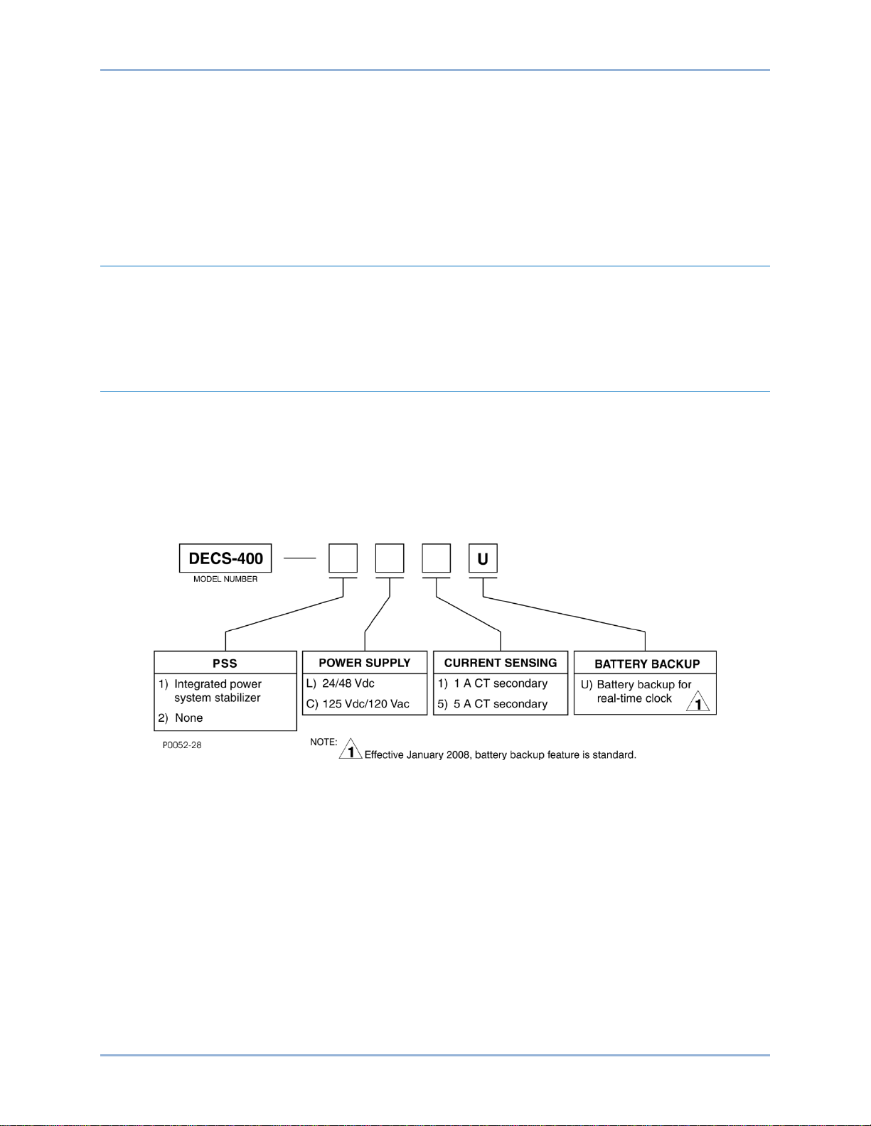
Style Number
The style number identification chart in Figure 1 defines the electrical characteristics and operational
features available in the DECS-400.
Figure 1. DECS-400 Style Chart
DECS-400 General Information
Page 20

8 9369700990 Rev R
General Information DECS-400
Page 21
9369700990 Rev R 9
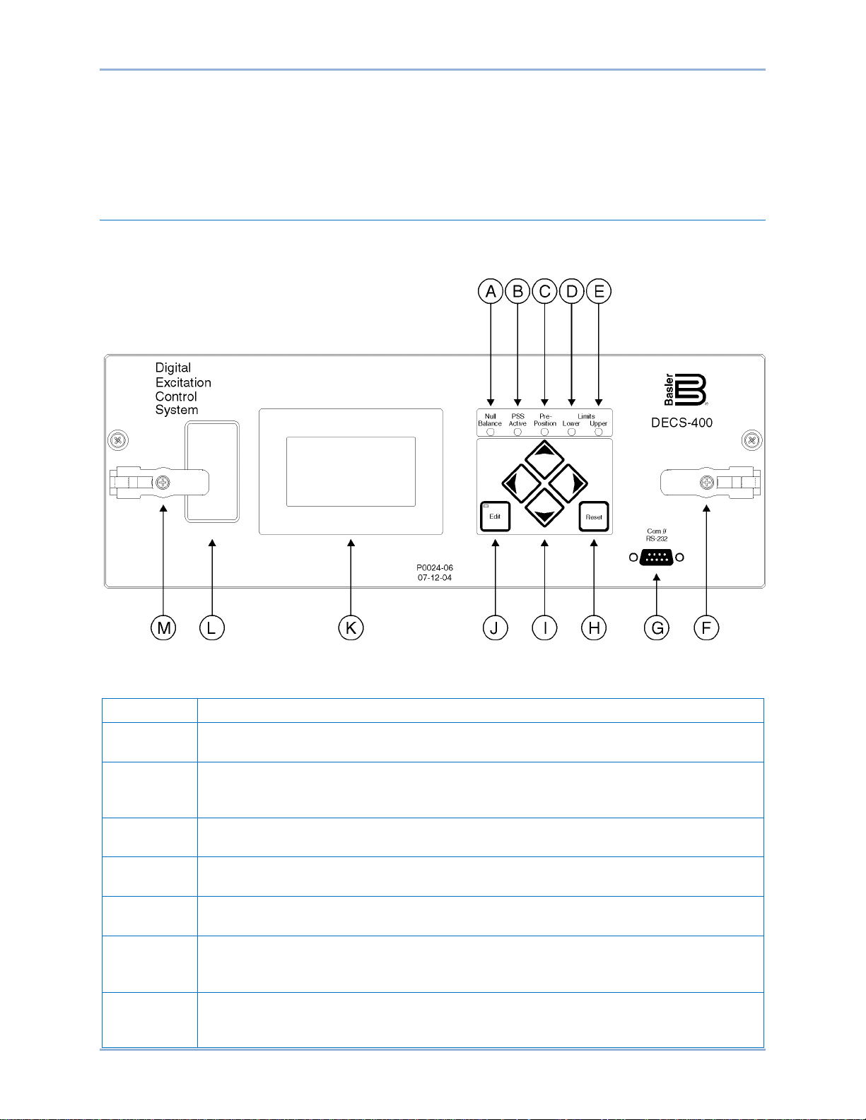
Locator
Description
A
Null Balance Indicator. This LED lights when the setpoint of the inactive operating
modes (AVR, FCR, Var, or Power Factor) match the setpoint of the active mode.
B
PSS Active Indicator. This LED lights when the integrated power system stabilizer is
disturbance.
C
Pre-Position Indicator. This LED lights when the setpoi nt of the active oper at in g mode is
at either of the two pre-position setting levels.
D
Lower Limit Indicator. This LED lights when the setpoi nt of the activ e operat in g mode is
decreased to the lower setpoint limit.
E
Upper Limit Indicator. This LED lights when the set po i nt of the activ e operat in g mode is
increased to the upper setpoint limit.
F
Latch. Two lever-style latches (locators F and M) secure the DECS-400 draw-out
draw-out assembly in place.
G
Communication Port. This R S-23 2 port has a female D B-9 connector for local
400).
Human-Machine Interface
This chapter describes the DECS-400 human-machine interface (HMI) and illustrates navigation of the
menu tree accessed through the front panel and LCD.
Controls and Indicators
DECS-400 controls and indicators are illustrated in Figure 2 and described in Table 1. The locators and
descriptions of Table 1 correspond to the locators shown in Figure 2.
Figure 2. Controls and Indicators
Table 1. Control and Indicator Descriptions
enabled and can generate a stabilizing signal in response to a power system
assembly in its case. A captive Phillips screw in each latch can be tightened to lock the
communication with a PC operating BESTCOMS software (supplied with the DECS-
DECS-400 Human-Machine Interfac e
Page 22

10 9369700990 Rev R
Locator
Description
H
Reset Pushbutton. This button is pressed to reset DECS-400 alarms or cancel a
settings editing session.
I
Scrolling Pushbuttons. These four buttons are used to scroll up, down, left, and right
the up and down scrolling pushbuttons change the value of the variable.
J
Edit Pushbutton. Pressing this button starts an editing session and enables changes to
pushbutton is pressed to save the setting changes and the LED turns off.
K
Display. The display consists of a 128 by 64 pixel, liquid crystal display (LCD) with LED
settings.
L
Identification Label. The identification label contains information such as the model,
style, and serial numbers and operating power and sensing current ratings.
M
Latch. Two lever-style latches (locators F and M) secure the DECS-400 draw-out
draw-out assembly in place.
through the menu tree displayed on the front panel display (locator K). During an editing
session, the left and right scrolling pushbuttons select the variable to be changed and
DECS-400 settings. When the Edit pushbutton is pressed to open an editing session,
an LED on the button lights. At the conclusion of the editing session, the Edit
backlighting. It serves as a local source of information provided by the DECS-400 and is
used when programming settings through the front panel. The LCD displays operations,
setpoints, loop gains, metering, protection functions, system parameters, and general
assembly in its case. A captive Phillips screw in each latch can be tightened to lock the
Menu System
The front panel menu system consists of a network of screens that enable the user to edit DECS-400
settings and view system parameters.
Menu Navigation
Movement through the front panel menu system is achieved by pressing the four, front-panel scrolling
pushbuttons (locator I in Figure 2).
Navigation aids assist the user in moving from screen to screen and are provided at the top and bottom
lines of each screen.
The top line of each screen contains the menu path which is similar to the path of a file on a PC. When
the menu path exceeds the width of the LCD, the first part of the menu path is replaced with two periods
(..) so that the last part of the path remains visible.
The bottom line indicates which menu screens can be accessed from the current screen by using the left,
lower, or right scrolling pushbuttons. The screens accessed by the left, lower, and right scrolling
pushbuttons are indicated by a <, v, and > symbol followed by an abbreviated menu name.
The front panel Reset pushbutton (locator H in Figure 2) provides a shortcut to the metering screen when
a settings editing session is not in progress.
Menu Structure
The front panel menu system has nine branches:
1. Operating. Start/stop, mode, and pre-position setpoint status.
2. Setpoints. Mode setting values such as AVR, FCR, droop, var, and power factor.
3. Loop Gains. PID settings.
4. Metering. Real-time metering of user-selected parameters and alarm messages.
5. Protection. Protective Function setting parameters.
Human-Machine Interface DECS-400
Page 23

9369700990 Rev R 11
6. Limiters. System limiters such as overexcitation and underexcitation.
7. PSS. The power system stabilizer menu consists of four sub-menus which include Control,
Parameters, Limiters, and Configuration.
8. System Parameters. The system parameters menu consists of nine sub-menus which include
Generator Data, Field Data, Transformers, Configuration, Output Contacts, Traverse Rates, Preposition Modes, Startup, and Tracking.
9. General Settings. The general settings menu consists of three sub-menus which include
Communications, LCD Contrast, and Real-Time Clock.
From the DECS-400 title screen, the Operating menu branch is accessed first by pressing the Down
pushbutton. Then, the remaining branches are accessed by pressing the left or right scrolling pushbuttons.
A detailed list of the menu system screens is provided below. The menu paths appear on the left and the
settings appear on the right.
\D400\OPER OPERATING
\OPERATE_1 START/STOP
AVR/MANUAL
PF OR VAR
FCR OR FVR
PREPOSN 1
PREPOSN 2
\OPERATE_2 VOLT MATCH
INT TRACK
EXT TRACK
CROSS CURNT
LINE DROP
DROOP
\OPERATE_3 INNER LP
\D400\SETPT SETPOINTS
\MODE_SET1 AVR MODE
FCR MODE
DROOP
VAR MODE
PF MODE
FVR MODE
\MODE1\RANGE_1 FINE V BD
AVR MIN
AVR MAX
FCR MIN
FCR MAX
KW LVL TRNS
\MODE1\RANGE_2 MIN VAR OUT
MAX VARA OUT
MAX LAG PF
MAX LEAD PF
FVR MIN
FVR MAX
\MODE1\RANGE_3 V MATCH BD
V MATCH REF
\MODE_SET2 LINE DROP
\PREP_SET1 AVR MODE
FCR MODE
VAR MODE
DECS-400 Human-Machine Interfac e
Page 24

12 9369700990 Rev R
PF MODE
FVR MODE
\PREP_SET2 AVR MODE
FCR MODE
VAR MODE
PF MODE
FVR MODE
\D400\GAIN LOOP GAINS
\P_AVR_GAINS PRI STB RG
AVR Kp
AVR Ki
AVR Kd
AVR Td
AVR Kg
\AVRG1\S_AVR_GAINS SEC STB RG
AVR Kp
AVR Ki
AVR Kd
AVR Td
AVR Kg
\P_FCR_GAINS FCR Kp
FCR Ki
FCR Kd
FCR Td
FCR Kg
\P_FVR_GAINS FVR Kp
FVR Ki
FVR Kd
FVR Td
FVR Kg
\LIM_GAINS OEL Ki
OEL Kg
UEL Ki
UEL Kg
SCL Ki
SCL Kg
\LIMGN\\LIM_GAINS2 VARL Ki
VARL Kg
\CTL_GAINS PF Ki
PF Kg
VAR Ki
VAR Kg
V MATCH Kg
\IN_LP_GAINS INNER LP Ki
INNER LP Kg
\D400_METERING METERING
See Metering Screen, Mete r ing Va lues for a list of the parameters available for display.
\D400_PROT PROTECTION
\V/HZ_PROT1 V/HZ ENABLE
V/HZ PCKUP
TIME DIAL
RESET DIAL
DLAY1 PKUP
DLAY1 TIME
Human-Machine Interface DECS-400
Page 25

9369700990 Rev R 13
\V/HZ_PROT2 DLAY2 PKUP
DLAY2 TIME
CURVE EXP
\PROT_ENAB1 FIELD OV
FIELD OC
STATOR OV
STATOR UV
NO SENSING
NO SNS->MAN
\ENAB1\S_PROT_ENE FIELD OV
FIELD OC
STATOR OV
STATOR UV
FIELD OT
LOSS FIELD
\PROT_ENAB2 FIELD OT
LOSS FIELD
FIT FAILED
POWER LOW
EX DIOD OD
EX DIOD SD
\P_PROT_LVL1 FIELD OV
FIELD OC
STATOR OV
STATOR UV
FIELD OT
LOS BAL V
\P_PROT_LVL1 FIELD OV
FIELD OC
STATOR OV
STATOR UV
FIELD OT
LOSS FIELD
\P_PROT_LVL2 LOS IMBAL V
LOSS FIELD
EDM OD RPL
EDM SD RPL
EDM INH LVL
\P_PROT_TMR1 FIELD OV
FIELD OC TD
STATOR OV
STATOR UV
NO SENSING
FIELD OT
\P_TM1\S_PROT_TMR1 FIELD OV
FIELD OC TD
STATOR OV
STATOR UV
FIELD OT
LOSS FIELD
\P_PROT_TMR2 LOSS FIELD
FIT FAILED
EX DIOD OD
EX DIOD SD
DECS-400 Human-Machine Interfac e
Page 26

14 9369700990 Rev R
\D400\LIMIT LIMITERS
\OPTION_1 OEL STYLE
OEL OPTION
UEL STYLE
OEL GROUP
UEL GROUP
SCL GROUP
\OPTION_2 UF OR V/HZ
OEL ENABLE
UEL ENABLE
SCL ENABLE
UEL FLTR TC
UEL VOL EXP
\P_ONLINE INST LIMIT
INST TIME
MED LIMIT
MED TIME
CONT LIMIT
\P_ONL\S_ONLINE INST LIMIT
INST TIME
MED LIMIT
MED TIME
CONT LIMIT
\P_OFFLINE OEL HI LIM
HI LIM TIME
OEL LO LIM
\P_OFL\S_OFFLINE OEL HI LIM
HI LIM TIME
OEL LO LIM
\P_OFFTAKOVR OEL MAX CUR
OEL MIN CUR
OEL TD
\P_OFT\S_OFFTAKOVR OEL MAX CUR
OEL MIN CUR
OEL TD
\P_ONTAKOVR OEL MAX CUR
OEL MIN CUR
OEL TD
\P_ONT\S_ONTAKOVR OEL MAX CUR
OEL MIN CUR
OEL TD
\P_UEL_CRV_X PNT 1 WATTS
PNT 2 WATTS
PNT 3 WATTS
PNT 4 WATTS
PNT 5 WATTS
\P_UEX\S_UEL_CRV_X PNT 1 WATTS
PNT 2 WATTS
PNT 3 WATTS
PNT 4 WATTS
PNT 5 WATTS
\P_UEL_CRV_Y PNT 1 VARS
PNT 2 VARS
PNT 3 VARS
PNT 4 VARS
PNT 5 VARS
Human-Machine Interface DECS-400
Page 27

9369700990 Rev R 15
\S_UEL_CRV_Y PNT 1 VARS
PNT 2 VARS
PNT 3 VARS
PNT 4 VARS
PNT 5 VARS
\P_SCLIM SCL HI LIM
HI LIM TIME
SCL LO LIM
INIT DELAY
\P_SCL\S_SCLIM SCL HI LIM
HI LIM TIME
SCL LO LIM
INIT DELAY
\VARLM VARL ENABLE
PRI SETPOINT
PRI INITDLY
SEC SETPNT
SEC INITDLY
VARL GROUP
\UF_V/HZ CORNER FREQ
UF SLOPE
V/HZ HI
V/HZ LO
V/HZ TIME
\D400\PSS POWER SYSTEM STABILIZER
\CONTROL PSS CONTROL
\P_BASIC_CTL SETTING GRP
TM PWRN TLD
TM PWR HYST
\P_CTL\S_BASIC_CTL SECONDARY
TM PWRN TLD
TM PWR HYST
\P_SOFT_SW1 SSW 0
SSW 1
SSW 2
SSW 3
SSW 4
SSW 5
\P_SS1\S_SOFT_SW2 SSW 0
SSW 1
SSW 2
SSW 3
SSW 4
SSW 5
\P_SOFT_SW2 SSW 6
SSW 7
SSW 8
SSW 9
SSW 10
\P_SS2\S_SOFT_SW2 SSW 6
SSW 7
SSW 8
SSW 9
SSW 10
DECS-400 Human-Machine Interfac e
Page 28

16 9369700990 Rev R
\D400\PSS\PARAMETER PSS PARAMETER S
\P_FILTER1 QUADTURE XQ
SCALER KPE
LP FLTR T11
LP FLTR T12
LP FLTR T13
RT FLTR TR
\P_FTR\S_FILTER
SCALER KPE
LP FLTR T11
LP FLTR T12
LP FLTR T13
RT FLTR TR
\P_FILTER2 HP FLTR H
HP FLTR TW1
HP FLTR TW2
HP FLTR TW3
HP FLTR TW4
\P_FTR\S_FILTER2 HP FLTR H
HP FLTR TW1
HP FLTR TW2
HP FLTR TW3
HP FLTR TW4
\P_FILTER3 NUM EXP N
NUM EXP M
\P_FTR\S_FILTER3 SECONDARY FILTER 3
NUM EXP N
NUM EXP M
\P_TRSN_FLTR FILTER 1 ZN
FILTER 1 ZD
FILTER 1 WN
FILTER 2 ZN
FILTER 2 ZD
FILTER 2 WN
\P_TSN\S_TRSN_FLTR FILTER 1 ZN
FILTER 1 ZD
FILTER 1 WN
FILTER 2 ZN
FILTER 2 ZD
FILTER 2 WN
\P_PHSE_COMP1 PHASE 1 TLD
PHASE 1 TLG
PHASE 2 TLD
PHASE 2 TLG
\S_PHSE_COMP1 PHASE 1 TLD
PHASE 1 TLG
PHASE 2 TLD
PHASE 2 TLG
\P_PHSE_COMP2 PHASE 3 TLD
PHASE 3 TLG
PHASE 4 TLD
PHASE 4 TLG
\S_PHSE_COMP2 PHASE 3 TLD
PHASE 3 TLG
PHASE 4 TLD
PHASE 4 TLG
QUADTURE XQ
Human-Machine Interface DECS-400
Page 29

9369700990 Rev R 17
\D400\PSS\LIMTERS PSS LIMITERS
\P_OUTPUT_LMT UPPER LIMIT
LOWER LIMIT
GAIN
\S_OUTPUT_LMT UPPER LIMIT
LOWER LIMIT
GAIN
\P_VOLT_LIMIT TIME CONST
SETPOINT
\P_VLT\S_VOLT_LMT TIME CONST
SETPOINT
\P_LOGIC_LMT FLTR NRM TM
FLTR LMT TM
OUT UPR LMT
OUT LWR LMT
OUT TM DLY
\P_LOG\S_LOGIC_LMT FLTR NRM TM
FLTR LMT TM
OUT UPR LMT
OUT LWR LMT
OUT TM DLY
\D400\PSS\CONFIG PSS CONFIGURATION
\CNFG SET GP SETTING GROUP CONFIGURATION
PWR TLD ENA
SG PWR TLD
ST PWR HYST
\PSS_ROC ROC ENABLE
ROC THRESH
ROC TM DLY
ROC BLKTIM
ROC LPF TC
ROC WF TC
\D400\SYSTEM SYSTEM PARAMETERS
\GENERATOR GENERATOR DATA
\GEN\GEN_DATA RATED VOLT
FREQUENCY
RATED KVA
\FIELD_DATA FIELD DATA
\FIELD_DATA1 FIELD VOLT
FIELD CURR
SHUNT RATING
ISOL BOX IN
FIELD RES
AMB TEMP
\FIELD_DATA_2 BRUSH DROP
POLE RATIO
\TRNSFRMRS TRANSFORMERS
\XFMRS\XFMR_DATA GEN PT PRI
GEN PT SEC
BUS PT PRI
BUS PT SEC
GEN CT PRI
GEN CT SEC
DECS-400 Human-Machine Interfac e
Page 30

18 9369700990 Rev R
\CONFIGURE CONFIGURATION
\CONFG\CNFG_DATA_1 FIELD TYPE
VLTAGE SNSE
MOTOR MODE
CURRNT SNSE
CT SELECT
\CNFG\CNFG_DATA_2 CTRL SIGNAL
AUX IN TYPE
AUX IN FCTN
CRSS I GAIN
TEMP MODE
\AUX_GAINS AVR MODE
FCR MODE
VAR MODE
PF MODE
FVR MODE
INNER/OUTER
\CONTACTS OUTPUT CONTACTS
\CNTCT\RELAY_1 OUTPT SENSE
OUTPUT TYPE
MOMENT TIME
\CNTCT\RELAY_2 OUTPT SENSE
OUTPUT TYPE
MOMENT TIME
\CNTCT\RELAY_3 OUTPT SENSE
OUTPUT TYPE
MOMENT TIME
\CNTCT\RELAY_4 OUTPT SENSE
OUTPT TYPE
MOMENT TIME
\CNTCT\RELAY_5 OUTPT SENSE
OUTPT TYPE
MOMENT TIME
\CNTCT\RELAY_6 OUTPT SENSE
OUTPT TYPE
MOMENT TIME
\TRVRS_HEAD TRAVERSE RATES
\TRVRS\TRVRS_RATE AVR MODE
FCR MODE
VAR MODE
PF MODE
FVR MODE
\PMODE_HEAD PRE-POSITION MODES
\PMODE\PREP_MODE1 AVR MODE
FCR MODE
VAR MODE
PF MODE
FVR MODE
\PREP1_RATES1 AVR TRAVEL
AVR RATE
FCR TRAVEL
FCR RATE
VAR TRAVEL
VAR RATE
\PREP1_RATES2 PF TRAVEL
PF RATE
Human-Machine Interface DECS-400
Page 31

9369700990 Rev R 19
FVR TRAVEL
FVR RATE
\PMODE\PREP_MODE2 AVR MODE
FCR MODE
VAR MODE
PF MODE
FVR MODE
\PREP2_RATES1 AVR TRAVEL
AVR RATE
FCR TRAVEL
FCR RATE
VAR TRAVEL
VAR RATE
\PREP2_RATES2 PF TRAVEL
PF RATE
FVR TRAVEL
FVR RATE
\SU_HEAD STARTUP
\START\P_STRTUP SS LEVEL
SS TIME
FLASH TIME
FLASH LEVEL
\P_STP\S_STRTUP SS LEVEL
SS TIME
\TRACK_HEAD TRACKING
\TRACK_TRACK_DATA INT RATE
INT DELAY
EXT RATE
EXT DELAY
\D400\SETUP GENERAL SETTINGS
\COMMS COMMUNICATIONS
\COMMS\BAUD_RATE COM0 RS232
COM1 RS485
COM2 RS485
\COMMS\MODBUS COM2 ADDR
COM2 DELAY
PARITY
STOP BITS
MODBUS TCP
\COMMS\ETHERNET IP
MAC
ST IP
NETM
GATEW
DHCP
\COMMS\NTP NTP
TIME ZONE
UPDATE TIME
NTP STATUS
\COMMS\VERSION VERSION
APP
DSP
BOOT
COMA
DECS-400 Human-Machine Interfac e
Page 32

20 9369700990 Rev R
Note
COMB
FLM
\CONTRAST LCD CONTRAST
\CLOCK CLOCK
\RTC\CLK_FORMAT TIME FORMAT
DST FORMAT
DATE FORMAT
Editing Settings
DECS-400 settings can be edited through the front panel. An editing session is initiated by navigating to
the screen containing the setting to be changed and pressing the Edit pushbutton. Edit mode is indicated
by a lit LED on the Edit pushbutton. A prompt to enter a password will appear on the display. Additional
information about using passwords is provided in Password Protection.
When security access is obtained through entry of the appropriate password, the first editable field of the
current screen is underlined. The underlined setting can be changed by pressing the up or down scrolling
pushbuttons to increase or decrease the setting. To edit another setting on the current screen, the left or
right scrolling pushbuttons are pressed to move the underline to the other editable setting fields.
Most setting changes are used immediately by the DECS-400.
However, the changes are not saved in nonvolatile memory until the
Edit pushbutton is pressed to terminate the editing session.
After all desired editing on a screen is completed, the changes can be saved or discarded. Changes are
saved by pressing the Edit pushbutton, which ends the edit session and saves the changes in nonvolatile
memory. Changes are discarded by pressing the Reset button, which ends the edit session and restores
the settings active prior to editing by reading them from nonvolatile memory. In both cases, the Edit pushbutton LED turns off to indicate that the editing session is terminated.
Security (password) access is not immediately lost when a settings editing session is terminated. Security
access ends after 10 minutes of no pushbutton activity. To modify settings on another screen with the
same access level, the user merely navigates to that screen and presses the Edit pushbutton to start a
new edit session.
This security access timeout differs from an edit session timeout. If 10 minutes of inactivity elapses during
an edit session, any changes that were made will be saved in nonvolatile memory and will be used by the
DECS-400. At this time, both edit access and security access are terminated.
Screens with Special Editing Modes
Several screens operate differently while in the edit mode. Examples of these screens are
\D400\OPER\OPERATE_1, ..\COMMS\BAUD_RATE, and ..\COMMS\MODBUS. Changes made to
settings on these screens are not used by the DECS-400 (nor saved in nonvolatile memory) until the Edit
pushbutton is pressed again.
Other examples of screens with different behavior in edit mode include the loop gains screens, which are
used to establish PID values (\D400\GAIN\PRI_GAINS and \D400\GAIN\SEC_GAINS). The first four
parameters on these screens represent tables (one table for primary gains and one table for secondary
gains) containing 20 sets of predefined PID (proportional + integral + derivative) values and one set of
user-definable values. The first parameters, PRI STB RG and SEC STB RG, represent the stability setting
number and are the index for the tables. Stability setting numbers 1 through 20 select predefined values
from the table and a setting of 21 enables the selection of user-defined values. The second, third, and
fourth parameters, AVR/FCR Kp, AVR/FCR Ki, and AVR/FCR Kd, are the actual entries in the table.
As long as the stability setting number is set at 21, then the Kp, Ki, and Kd parameters may be
individually edited. Changed values are not used by the DECS-400 until they are saved by pressing the
Human-Machine Interface DECS-400
Page 33

9369700990 Rev R 21
Screen
Setting
\D400\OPER\OPERATE_1
Start/Stop control
AVR/FCR mode
Power Factor/Var mode
Pre-position 1 enable
Pre-position 2 enable
\D400\OPER\OPERATE_2
Voltage matching enable
Internal tracking enable
External tracking enable
Cross-current compensation enable
Line drop compensation enable
Droop enable
\D400\SETPT\MODE_SET
AVR mode setpoint
FCR mode setpoint
Droop setpoint
Var mode setpoint
Power Factor mode setpoint
Line drop setpoint
\D400\SETPT\PREP_SET1
Fine voltage band setting – pre-position 1
Minimum AVR mode setpoint – pre-position 1
Maximum AVR mode setpoint – pre-position 1
Minimum FCR mode setpoint – pre-position 1
Maximum FCR mode setpoint – pre-positi on 1
\D400\SETPT\PREP_SET2
AVR mode setpoint – pre-position 2
FCR mode setpoint – pre-position 2
Var mode setpoint – pre-position 2
Power Factor setpoint – pre-position 2
Edit pushbutton. Kp, Ki, and Kd may not be edited when the stability setting number is set at 1 through
20.
If the DECS-400 is operating with user-defined PID values and the stability setting number is changed to
a value of 1 to 20, the user-defined Kp, Ki, and Kd values are lost. The next time that user-defined values
for a stability setting of 21 are required, they must be manually entered and saved.
Password Protection
All DECS-400 settings that can be edited at the front panel are password protected. A password is
required at the start of any settings editing session. Password access expires 10 minutes after the last
entry is received at the front panel.
There are two levels of password access: global and setpoint. Global password access permits changes
to all settings that can be edited through the front panel. Setpoint password access permits changes to a
limited selection of settings. Settings that can be changed with setpoint password access are listed in
Table 2. All editable settings on a single menu screen have the same password access level.
Table 2. Settings Protected by Setpoint Password
DECS-400 Human-Machine Interfac e
Page 34

22 9369700990 Rev R
Caution
Metering Label
Description
Bus Hz
Bus frequency
Bus V
Bus voltage
EDM OD
Exciter diode monitor open diode percent ripple
EDM SD
Exciter diode monitor shorted diode percent ripple
F Temp
Field temperature
Field V
Field voltage
Fld I
Field current
Gen Hz
Generator frequency
\D400\METER\ADJUST
Watts VAr Ic
0.000 0.000 0.000
ALARMS (PRESS < OR >)
SETPT
% RNG
UNIT IS OFF
120 / 75.0%
Metering Values (3)
Setpoint / % of Range
Alarm s Message
Operating M ode
P0025-04
08-16-04
DECS-400 units are delivered with the same global and setpoint access password: DECS4. When the
global and setpoint passwords are identical, the DECS-400 grants global access when the correct
password is entered. In order to permit setpoint-only access, the setpoint access password must differ
from the global access password. If the user attempts to start an edit session on a screen requiring global
access while only setpoint access is granted, the setpoint access is revoked and the user is prompted to
enter a global access password.
Passwords may be changed using BESTCOMS software (provided with the DECS-400) and a password
can contain from one to six alphanumeric characters. To provide security against unauthorized setting
changes, the passwords should be changed after commissioning. Once changed, the passwords should
be stored in a secure location. If the user-defined passwords are lost or forgotten, the default password
(DECS4) can be restored by simultaneously pressing the Edit and Reset pushbuttons during DECS-400
power-up.
Pressing the Edit and Reset pushbuttons during DECS-400 power-up
replaces all user-programmed settings with the default settings.
Restoring the default password also replaces all user-programmed settings with the default values.
Before performing this procedure, BESTCOMS software should be used to save a DECS-400 settings
file. After the default settings are loaded while restoring the default password, the settings file can be
uploaded to the DECS-400 and new passwords can be assigned.
Metering Screen
Metering screen information is displayed in five fields: metering values, alarms message, setpoint value,
setpoint—percent of range, and operating mode. The metering screen fields are illustrated in Figure 3.
Figure 3. Metering Screen Information
Metering Values
Metering values for three user-selectable parameters are displayed. Table 3 lists the metering parameters
available for display on the DECS-400 metering screen.
Table 3. Selectable Metering Parameters
Human-Machine Interface DECS-400
Page 35

9369700990 Rev R 23
Metering Label
Description
Hz/sec
Rate of frequency change
I Avg
Average of three generator line currents
Ia
A-phase generator line current
Ib
B-phase generator line current
Ic
C-phase generator line current
NSeq I
Negative sequence current
NSeq V
Negative sequence voltage
PF
Power factor
PSeq I
Positive sequence current
PSeq V
Positive sequence voltage
V a-b
A-phase to B-phase generator rms voltage
V Aux
Accessory input voltage
V Avg
Average of three generator line-to-line voltages
V b-c
B-phase to C-phase generator rms voltage
V c-a
C-phase to A-phase generator rms voltage
VA
Generator load VA
VAr
Reactive power
Watts
Generator load watts
Operating Mode
Mode Message
Setpoint Field Quantity
Off
UNIT IS OFF
Setpoint from last mode
Voltage Matching
VOLTAGE MATCHING
AVR setpoint
FCR (Manual)
FCR (MANUAL)
FCR setpoint
AVR (Auto)
AVR (AUTO)
AVR setpoint
Droop
DROOP
AVR setpoint
Var Control
VAR CONTROL
Var setpoint
Power Factor Control
POWER FACTOR CONTROL
PF setpoint
The DECS-400 uses auto-ranging to display up to four digits of resolution plus a decimal point. If needed,
a multiplier such as k for kilo (1,000) or M for mega (1,000,000) is used. Negative values with magnitudes
greater than 999.9 are displayed with three digits of resolution.
Setpoint
The setpoint field displays the setpoint for the active mode of operation. Table 4 lists the relationship
between the mode of operation and the setpoint field quantity.
Table 4. Setpoint Field Operating Mode Cross-Reference
Percent of Range
This field displays the setpoint expressed as a percentage of the available adjustment range. The
relationship between this field and the setpoint field is linear. For example, a setpoint adjusted to the
minimum value would be displayed as 0.0%, a setpoint adjusted to the middle of the adjustment range
would be displayed as 50.0%, and a setpoint adjusted to the maximum value would be displayed as
100.0%.
DECS-400 Human-Machine Interfac e
Page 36

24 9369700990 Rev R
Annunciation Message
Duration of Message
CLOCK RESET
Maintained until reset
CURRENT UNBALANCE
Automatically reset
EXCESSIVE V/HZ
Maintained until reset
EXCITER DIODE OPEN
Maintained until reset
EXCITER DIODE SHO RT
Maintained until reset
FAILED TO BUILD UP
Maintained until reset
FIELD OVER TEMP
Maintained until reset
FIELD OVERCURRENT
Maintained until reset
FIELD OVERVOLTAGE
Maintained until reset
GEN. OVERVOLTAGE
Maintained until reset
GEN. UNDERVOLTAGE
Maintained until reset
LOSS ISOLATION MODULE
Automatically reset
LOSS OF FIELD
Maintained until reset
LOSS OF IRIG
Automatically reset
LOST VOLTAGE SENSING
Maintained until reset
OVEREXCITATIO N L IM I T
Clears 2 s after end of event
POWER BELOW THRESHOLD
Automatically reset
POWER SUPPLY LOW
Automatically reset
PSS BLOCK
Automatically reset
SPEED FAILURE
Automatically reset
STATOR CURRENT LIMIT
Clears 2 s after end of event
SYSTEM BELOW 10 HZ
Clears 2 s after end of event
UNDEREXCITATION LIMIT
Clears 2 s after end of event
UNDERFREQUENCY
Clears 2 s after end of event
VAR LIMIT
Automatically reset
VOLTAGE LIMIT
Automatically reset
VOLTAGE UNBALANCE
Automatically reset
Alarms Message
The alarms message line remains blank during normal operating conditions. If an enunciable condition
occurs, “ALARMS (PRESS < OR >)” is displayed. Information about the condition is obtained by viewing
the alarm message screen.
Alarm Message Screen
Pressing either the left or right scrolling pushbuttons, while viewing the metering screen, displays the
alarm message screen. This screen displays up to six messages identifying the conditions that led to the
most recent annunciations.
lists the annunciations that may appear on the alarm message screen. When more than one message is
listed, the newest messages are added to the bottom of the list. Once the list contains six messages, any
further annunciations will cause the oldest message to be deleted from the top of the list.
Table 5. Alarm Messages
The list of alarm messages can be cleared by pressing the Reset pushbutton. Pressing the Reset
pushbutton also sends the display back to the metering screen and clears the metering screen alarms
Human-Machine Interface DECS-400
Page 37

9369700990 Rev R 25
message. If a condition that led to an annunciation is still present when the alarm message screen is
cleared, then a new annunciation message will be generated. The list of annunciations on the alarm
message screen is retained if the user exits the screen by using the left, right, or up scrolling pushbuttons.
However, the metering screen will not indicate when a new annunciation occurs because the alarms
message will always be present.
Operating Mode
This line of the metering screen indicates the DECS-400’s current mode of operation. Table 4 lists the
message displayed for each DECS-400 operating mode.
DECS-400 Human-Machine Interfac e
Page 38

26 9369700990 Rev R
Human-Machine Interface DECS-400
Page 39

9369700990 Rev R 27
Functional Description
This chapter describes how the DECS-400 functions and explains its operating features. To ease understanding, DECS-400 functions are illustrated in the block diagram of Figure 4. A detailed description of
each function block is provided in the paragraphs under the heading of DECS-400 Function Blocks .
Figure 4. DECS-400 Function Blocks
DECS-400 Function Blocks
The following paragraphs describe each of the function blocks illustrated in Figure 4. The function of each
block is explained along with the operation of all function block inputs and outputs.
Analog Input Circuits
The DECS-400’s analog sensing inputs are described in the following paragraphs.
DECS-400 Functional Description
Page 40

28 9369700990 Rev R
Generator Voltage
Generator sensing voltage is supplied to DECS-400 terminals A9 (E1), A10 (E2), and A11 (E3) through
external, user-supplied, isolation transformers with a nominal output rating of 120 Vac or 240 Vac. The
DECS-400 automatically selects the proper generator voltage sensing range based on the generator
voltage sensing transformer’s secondary voltage value entered in the DECS-400.
DECS-400 generator voltage sensing inputs consist of an A-phase to B-phase (V
phase to C-phase voltage input (V
The V
CA voltage sensing input is used by the DECS-400 to calculate generator frequency. Sensed
BC), and a C-phase to A-phase voltage input (VCA).
AB) voltage input, a B-
voltage is filtered (through a zero-crossing detector) to eliminate multiple zero crossings during one
fundamental period.
Bus Voltage
Bus sensing voltage is supplied to DECS-400 terminals A13 (BUS1) and A14 (BUS3) through external,
user-supplied isolation transformers with a nominal output rating of 120 Vac or 240 Vac. The DECS-400
automatically selects the proper bus voltage sensing range based on the bus voltage sensing
transformer’s secondary voltage value entered in the DECS-400.
The sensed bus voltage is filtered (through a zero-crossing detector) to eliminate multiple zero crossings
during one fundamental period. This input is compared with the generator sensing voltage for the purpose
of voltage matching.
Line Current
The line current sensing inputs consist of an A-phase current input (IA), a B-phase current input (IB), and
a C-phase current input (I
C).
Generator sensing current is supplied to DECS-400 terminals A1 and A2 (CTA), A3 and A4 (CTB), and
A5 and A6 (CTC) through external, user-supplied current transformers (CTs) with a secondary rating of 1
Aac (DECS-400 style XX1X) or 5 Aac (DECS-400 style XX5X).
When only one phase of generator current is sensed, the I
B input (terminals A3 and A4) must be used.
A minimum of two generator current phases must be sensed for PSS applications.
Cross-Current Compensation
This input (CCC) is used when generators are operating in cross-current compensation (reactive
differential) mode.
B-phase generator sensing current is supplied to DECS-400 terminals A7 and A8 through an external,
user-supplied CT with a secondary rating of 1 Aac (DECS-400 style XX1X) or 5 Aac (DECS-400 style
XX5X).
Accessory Input
The accessory input can be configured to receive an external excitation setpoint control signal, the control
signal from an external PSS, or for limiter scaling. (For more information about limiter scaling, see Limiter
Functions, Limiter Scaling later in this chapter.) The accessory input accepts either a –10 Vdc to +10 Vdc
signal at DECS-400 terminals A16 (+) and A17 (–) or a 4 mAdc to 20 mAdc control signal at A19 (+) and
A20 (–).
When a current input type is selected, the input current is converted by the DECS-400 to a voltage signal
in the range of –5 to +5 Vdc. The following equation is used by the DECS-400 when converting the
applied current into a voltage.
= 0.625 (I – 12) where: Vaux = the calculated voltage signal
V
aux
I = current applied to the accessory input (in milliamperes)
For setpoint control, V
is multiplied by the appropriate accessory gain setting: AVR mode gain, FCR
aux
mode gain, Var mode gain, or Power Factor mode gain. The accessory input can be active in all four
operating modes.
Functional Description DECS-400
Page 41

9369700990 Rev R 29
In AVR mode, the accessory input signal is multiplied by the AVR mode gain setting, which defines the
setpoint change as a percentage of the rated generator voltage.
In FCR mode the accessory input signal is multiplied by the FCR mode gain setting, which defines the
setpoint change as a percentage of the rated field current.
In Var mode, the accessory input signal is multiplied by the Var mode gain setting, which defines the
setpoint change as a percentage of the rated apparent power for the generator.
In Power Factor mode, the accessory input signal is multiplied by the Power Factor mode gain setting and
then divided by 100 to define the power factor setpoint change.
Field Voltage and Current
The DECS-400 receives field voltage and current signals from the field isolation module supplied with the
DECS-400. Field voltage and current signals are transmitted from the field isolation module through a
dedicated cable terminated at DECS-400 connector J1.
For field voltage sensing, the field isolation module accepts a range of nominal voltages of 63 Vdc, 125
Vdc, 250 Vdc, 375 Vdc, or 625 Vdc. The applied field voltage may be ±300% of the nominal value. The
field isolatio n module supplies the DECS-400 with a field voltage signal over the range of 0.9 to 9.1 Vdc,
where 5.0 Vdc equals zero field voltage.
For field current sensing, the field isolation module accepts nominal current shunt output voltages of 0 to
50 mVdc or 0 to 100 mVdc. The applied shunt voltage may be up to 300% of either range. The field
isolation module supplies the DECS-400 with a field current signal over the range of 2.0 to 9.5 Vdc, where
2.0 Vdc equals zero field current.
Front Panel Keyboard
The front panel keyboard consists of six pushbuttons.
Four of the pushbuttons are designated for scrolling up, down, left, and right through the menu tree
displayed on the front panel display. During an editing session, the left and right scrolling pushbuttons
select the variables to be changed and the up and down scrolling pushbuttons change the value of the
variable.
The Reset pushbutton is pressed to reset DECS-400 alarms or cancel a settings editing session.
The Edit pushbutton is pressed to begin an editing session and enables changes to DECS-400 settings.
When the Edit button is pressed to open an editing session, an LED on the button lights. At the
conclusion of the editing session, the Edit pushbutton is pressed to save the editing changes.
Contact Input Circuits
Sixteen contact inputs are provided for initiating DECS-400 actions. Six of the contact inputs are fixedfunction inputs: AVR, Manual, Lower, Raise, Start, and Stop. The remaining ten contact inputs are
programmable inputs.
Each contact input has an isolated, interrogation voltage of 12 Vdc and accepts dry relay/switch contacts
or an open-collector output from a PLC.
DECS-400 contact inputs are described in the following paragraphs.
AVR
This input accepts a momentary contact closure that places the DECS-400 in AVR (automatic voltage
regulation) mode. If the DECS-400 receives AVR and FCR contact inputs simultaneously, the FCR input
has priority. AVR contact input connections are made at terminals B4 (AVR) and B5 (COM).
Manual
This input accepts a momentary contact closure that places the DECS-400 in Manual mode. If the DECS400 receives AVR and Manual contact inputs simultaneously, the Manual input has priority. When
operating in Manual mode, the DECS-400 regulates (as configured in BESTCOMS™) either the level of
DECS-400 Functional Description
Page 42

30 9369700990 Rev R
field current (FCR) or the level of field voltage (FVR). Manual contact input connections are made at
terminals B6 (MAN) and B5 (COM).
Raise
This input increases the active, operating setpoint. The raise setpoint function is active as long as the
contact is closed. The raise increment is a function of the setpoint range of adjustment and the active
mode traverse rate. The increments are directly proportional to the adjustment range and inversely
proportional to the traverse rate. This input has no effect when the active pre-position mode is Maintain.
Raise contact input connections are made at terminals B7 (RAISE) and B8 (COM).
Lower
This input decreases the active, operating setpoint. The lower setpoint function is active as long as the
contact is closed. The lower increment is a function of the setpoint range of adjustment and the active
mode traverse rate. The increments are directly proportional to the adjustment range and inversely
proportional to the traverse rate. This input has no effect when the active pre-position mode is Maintain.
Lower contact input connections are made at terminals B9 (LOWER) and B8 (COM).
Start
This input accepts a momentary contact closure that enables the DECS-400. If the DECS-400 receives
Start and Stop contact inputs simultaneously, the Stop input has priority. Start contact input connections
are made at terminals B1 (START) and B2 (COM).
Stop
This input accepts a momentary contact closure that disables the DECS-400. If the DECS-400 receives
Stop and Start contact inputs simultaneously, the Stop input has priority. Stop contact input connections
are made at terminals B3 (STOP) and B2 (COM).
SW1 – SW10
These user-programmable inputs can be connected to monitor the status of excitation system contacts
and switches. Then, using BESTCOMS, these inputs can be used as part of a user-configured logic
scheme to control and annunciate a variety of system conditions and contingencies. Information about
using SW1 through SW10 is provided in the BESTCOMS Soft w ar e chapter.
Digital Signal Processor
The digital signal processor (DSP) supports measurement, control (output and converters), metering
functions, and filtering. It controls both the analog-to-digital converter (ADC) and the digital-to-analog
converter (DAC). All analog input signals from the ADC are filtered by finite impulse response (FIR) filters.
AC signals are also filtered by infinite impulse response (IIR) filters, and dc signals (field voltage and
current) are filtered by averaging filters. Output data to the DAC are used to generate the control output
signals.
Microprocessor
The microprocessor performs control, measurement, computation, self-test, and c ommu nicat ion funct ions
by using its embedded programming (firmware) and the nonvolatile settings stored in its memory.
IRIG Port
When a valid time code signal is detected at the IRIG port, it automatically synchronizes the DECS-400’s
internal clock with the time code signal. Because the IRIG time code signal does not contain year
information, it is necessary for the user to enter the date even when using an IRIG source. Year
information is stored in nonvolatile memory so that when operating power is restored after an outage and
the clock is re-synchronized, the current year is restored.
The IRIG input is fully isolated and accepts a demodulated (dc level-shifted) signal. For proper
recognition, the IRIG signal applied to the DECS-400 must have a logic high level of no less than 3.5 Vdc
and a logic low level that is no higher than 0.5 Vdc. The input signal voltage range is –10 Vdc to +10 Vdc.
Functional Description DECS-400
Page 43

9369700990 Rev R 31
Input resistance is nonlinear and approximately 4 kΩ at 3.5 Vdc and 3 kΩ at 20 Vdc. IRIG signal
connections are made at terminals D1 (IRIG+) and D2 (IRIG–).
Memory Circuits
The DECS-400 has three types of memory circuits: flash memory, random access memory (RAM), and
electrically-erasable, programmable, read-only memory (EEPROM). Flash memory is nonvolatile and
retains the operating software (firmware). RAM is volatile and serves as temporary storage for data.
EEPROM is nonvolatile and stores DECS-400 settings.
Digital to Analog Converter
Digital input data from the digital signal processor (DSP) is converted by the digital-to-analog converter
(DAC) into analog signals for controlling the excitation level. Output data from the DAC may be either a
voltage signal or current signal. Signal selection is made through BESTCOMS or the front panel HMI.
A second pair of DACs supply metering signals to the DECS-400 meter driver output terminals.
Control Output Circuits
Analog signals from the DAC are output to switches controlled by the DSP. There are three control signal
options. A control signal over the range of 0 to 10 Vdc, –10 to 10 Vdc, or 4 to 20 mAdc may be selected.
Control signal selection is made through BESTCOMS or the front panel HMI.
Meter Driver Circuits
Two analog signals from a second DAC are output from the microprocessor. A meter driver signal over
the range of 4 to 20 mAdc may be configured to represent one of the DECS-400 metered values. Each
driver circuit can be configured for a different metered value and configured to represent a specific range
of the metered value. The parameters available for metering are listed below:
• Auxiliary Voltage Input
• AVR PID Error Signal Input
• Bus Frequency
• Bus Voltage
• Comp. Freq. Deviation
• Control Output
• Cross Current Input
• Field Current
• Field Temperature
• Field Voltage
• Frequency Response
• Generator Apparent Power
• Generator Average Current
• Generator Average Voltage
• Generator Current Ia
• Generator Current Ib
• Generator Current Ic
• Generator Frequency
• Generator Power Factor
• Generator Reactive Power
• Generator Real Power
• Generator Voltage Vab
• Generator Voltage Vbc
• Generator Voltage Vca
• Negative Sequence Current
• Neg. Sequence Voltage
• Null Balance Level
• OEL Controller Output
• PF Mode Output
• Phase Angle Ia – Vca
• Phase Angle Iaux – Vca
• Phase Angle Ib – Vca
• Phase Angle Ic – Vca
• Phase Angle Vab
• Phase Angle Vbc
• PID Integrator State
• Position Indication
• Positive Sequence Current
• Positive Sequence Voltage
• PSS Electrical Pow er
• PSS Filtered Mech. Power
• PSS Final Output
• PSS Lead-Lag #1
• PSS Lead-Lag #2
• PSS Lead-Lag #3
• PSS Lead-Lag #4
• PSS Mechanical Power
• PSS Mech. Power LP #1
• PSS Mech. Power LP #2
• PSS Mech. Power LP #3
• PSS Mech. Power LP #4
• PSS Post-Limit Output
• PSS Power HP #1
• PSS Pre-Limit Output
• PSS Speed HP #1
• PSS Synthesized Speed
• PSS Terminal Voltage
• PSS Torsional Filter #1
• PSS Torsional Filter #2
• PSS Washed Out Power
• PSS Washed Out Speed
• Rate of Frequency Change
• SCL Controller Output
• Terminal Freq. Deviation
• Time Response
• UEL Controller Output
• Var Limiter Output
Relay Output Contacts
DECS-400 output contacts consist of a dedicated On/Off output, a dedicated Watchdog output, and six
programmable outputs.
DECS-400 Functional Description
Page 44

32 9369700990 Rev R
On/Off
The SPST On/Off output contacts close when the DECS-400 is enabled and open when the DECS-400 is
disabled. On/Off output connections are made at terminals C9 and C10.
Watchdog
The SPDT Watchdog output contacts change state during the following conditions:
• No operating power is applied to the DECS-400
• DECS-400 power-up (approximately 8 seconds)
• DECS-400 firmware ceases normal execution
Watchdog output connections are made at terminals C6 (NC), C7 (COM), and C8 (NO).
Programmable
The programmable output contacts (Relay #1, #2, #3, #4, #5, and #6) can be user-configured to
annunciate DECS-400 status, active alarms, active protection functions, and active limiter functions. Each
programmable output can be individually configured as normally-open (NO) or normally-closed (NC).
Each programmable output can also be configured as momentary, maintained as long as the triggering
condition is present, or latched until manually reset. The duration of a momentary contact’s annunciation
is programmable from 0.10 to 5 seconds in 50 millisecond increments. Relay #1 connections are made at
terminals C11 and C12, Relay #2 connections are made at terminals C13 and C14, Relay #3 connections
are made at terminals C15 and C16, Relay #4 connections are made at terminals C17 and C18, Relay #5
connections are made at terminals C19 and C20, and Relay #6 connections are made at terminals C21
and C22.
To make output identification easier, each programmable output may be assigned a user-selected name.
Front Panel LEDs
Six LEDs indicate setpoint status (Null Balance, Pre-Position, Lower Limit, and Upper Limit), power
system stabilizer status (PSS Active), and Edit mode status (Edit).
Front Panel LCD
The backlit liquid crystal display serves as a local source of information provided by the DECS-400 and is
used when programming settings through the front panel. The LCD displays operations, setpoints, loop
gains, metering, protection functions, system parameters, and general settings.
RS-232 Communication Port
This ASCII communication port, designated Com 0, consists of a female DB-9 connector intended for
local communication with a PC operating BESTCOMS software.
RS-485 Communication Ports
The DECS-400 has two rear-panel, RS-485 communication ports designated Com 1 and Com 2.
Com 1 is dedicated for ASCII communication with a secondary, redundant DECS-400. Com 1
connections are made at terminals D5 (A), D6 (B), and D7 (C).
Com 2 is intended for communication with a remote terminal using the Modbus protocol. Two versions of
the Modbus protocol are supported by the DECS-400. Depending upon the communication option
selected, either Modbus RTU can be enabled or Modbus TCP can be enabled. Simultaneous use of
Modbus RTU and Modbus TCP is not possible in the DECS-400. Com 2 connections are made at
terminals D10 (A), D11 (B), and D12 (C).
Refer to the General Information chapter for the available range of communication settings for Com 1 and
Com 2.
Functional Description DECS-400
Page 45

9369700990 Rev R 33
Ethernet Port
A rear-panel, RJ-45 connector, designated Com 3, enables communication with the DECS-400 over a
10BASE-T Ethernet network.
Modem
An internal telephone modem enables an off-site PC operating BESTCOMS software to dial into a DECS400 and view DECS-400 settings, metering values, and system status information. Modem access is
read-only; this prevents system control or the changing of DECS-400 settings. Information about initiating
modem communication is provided in the BESTCOMS Softw ar e chapter.
The FCC part 68 approved modem connects through a rear-panel, RJ-11 connector designated J1. The
modem communication baud rate is fixed at 9600.
Power Supply
DECS-400 units with a style number of XLXX, accept nominal operating power of 24 Vdc or 48 Vdc at
terminals C4 (BATT–) and C5 (BATT+). DECS-400 units with a style number of XCXX have two operating
power inputs. One input accepts 125 Vdc at terminals C4 (BATT–) and C5 (BATT+). A second input
accepts 120 Vac at terminals C2 (N) and C3 (L). Refer to the Specifications chapter for the acceptable
input voltage ranges.
The power supply provides 5 Vdc, ±12 Vdc, and 24 Vdc operating power for DECS-400 circuitry and ±12
Vdc operating power for the Field Isolation Module.
Startup Functions
DECS-400 startup functions include a soft start function, field flashing function, voltage matching, and a
buildup failure annunciation function.
Soft Start Function
During startup, the soft start function prevents voltage overshoot by controlling the rate at which the
generator terminal voltage builds toward the setpoint. Soft start is active in AVR (automatic) and FCR
(manual) control modes. During system startup, the voltage reference adjustment is based on two
parameters: level and time. The Soft Start Level is adjustable from 0 to 90%. Soft Start Time is adjustable
from 1 to 7,200 seconds. Figure 5 illustrates a plot of the voltage reference when the soft start level is
30%, the soft start time is 8 seconds, and the voltage setpoint is at 100%.
Field Flash/Buildup
During startup, the field flashing/buildup function applies and removes field flashing from an external field
flashing source. Field flashing/buildup is active in AVR (Auto) and FCR (Manual) control modes. During
system startup, the application of field flashing is based on two parameters: level and time. The field flash
dropout level is adjustable from 0 to 100% of the active mode setpoint and determines when field flashing
is removed. The maximum field flash time is adjustable from 1 to 50 seconds and defines the maximum
duration that field flashing is applied. In FCR control mode, the field flash dropout level is expressed as a
percentage of the field current setpoint and uses the field current level to determine when buildup has
occurred. In AVR control mode, the field flash dropout level is expressed as a percentage of the generator
voltage setpoint and uses the generator voltage level to determine when buildup has occurred.
DECS-400 Functional Description
Page 46

34 9369700990 Rev R
Figure 5. Soft Start Voltage Reference
Failure to Build Up
The failure to build up function monitors if the active control mode parameter—generator voltage in AVR
mode or field current in FCR mode—has reached the field flash dropout level prior to the maximum field
flash time expiring. If the active control mode parameter does not reach the field flash dropout level before
the maximum field flash time expires, a failure to build up is annunciated and the DECS-400 is disabled
(placed in Stop mode).
A failure to build up is annunciated at the front panel display, through BESTCOMS software, and the RS485 Modbus interface (Com 2). Any of the DECS-400‘s six programmable output relays can be configured
to annunciate a failure to build up.
Voltage Matching
Voltage matching is active in AVR (Automatic) control mode and automatically adjusts the AVR mode
setpoint to match the sensed bus voltage. Voltage matching is based on two parameters: band and
matching level.
The band is adjustable from 0 to 20% of the sensed bus voltage and defines the window in which the
generator voltage must be for voltage matching to occur.
The generator to bus PT matching level is adjustable from 90 to 120% and defines the percentage of the
sensed bus voltage to which the generator sensed voltage will be adjustable. The voltage matching
function utilizes the metered generator and bus voltage values to determine band and matched levels.
Control Modes
The DECS-400 provides four control modes: Automatic Voltage Regulation (AVR), Manual, Power Factor
(PF), and Reactive Power (Var).
Functional Description DECS-400
Page 47

9369700990 Rev R 35
AVR
AVR mode is selected by a momentary contact input applied to terminals B4 and B5. AVR mode may also
be selected through BESTCOMS. Wh en oper at in g in AVR mode, the DECS-400 adjusts the level of
excitation to maintain the desired generator terminal voltage level. The desired terminal voltage level is
entered (in primary generator voltage) through BESTCOMS or the front panel HMI as the AVR Setpoint
setting. The setting range of the AVR Setpoint depends on the generator ratings entered and the
minimum and maximum AVR settings. Once the AVR Setpoint is established, it can be fine tuned by
applying a contact input to terminals B7 and B8 (raise) or B8 and B9 (lower). Raise and lower inputs may
also be applied through BESTCOMS or Modbus. AVR Min and AVR Max settings control the range of
adjustment for the AVR setpoint. The AVR Min setting has a setting range of 70 to 100% of the rated
generator voltage and the AVR Max setting has a setting range of 100 to 110% of the rated generator
voltage. The length of time required to adjust the AVR setpoint from one limit to the other is controlled by
the AVR Traverse Rate setting. The AVR Traverse Rate is adjustable from 10 to 200 seconds.
Manual
Manual mode is selected by a momentary contact input applied to terminals B5 and B6. Manual mode
can also be selected through BESTCOMS. If enabled, Manual mode can be selected automatically when
a loss of sensing condition occurs. Manual mode can be configured through BESTCOMS to regulate
either the field current (FCR) or the field voltage (FVR).
FCR
When operating in FCR (field current regulation) mode, the DECS-400 adjusts the control output to
maintain the desired level of field current. The desired level of field current is entered through
BESTCOMS or the front panel HMI as the FCR Setpoint setting. The setting range of the FCR Setpoint
depends on the field type selected and other associated settings. Once the FCR setpoint is established, it
can be fine tuned by applying a contact input to terminals B7 and B8 (raise) or B8 and B9 (lower). Raise
and lower inputs may also be applied through BESTCOMS or Modbus. FCR Min and FCR Max settings
control the range of adjustment for the FCR setpoint. The FCR Min setting has a setting range of 0 to
100% of the rated field current and the FCR Max setting has a setting range of 0 to 120% of the rated
field current. The length of time required to adjust the FCR setpoint from one limit to the other is controlled
by the FCR Traverse Rate setting. The FCR Traverse Rate is adjustable from 10 to 200 seconds.
FVR
When operating in FVR (field voltage regulation) mode, the DECS-400 adjusts the control output to
maintain the desired level of field voltage. The desired level of field voltage is entered through
BESTCOMS or the front panel HMI as the FVR Setpoint setting. The setting range of the FVR Setpoint
depends on the field type selected and other associated settings. Once established, the FVR setpoint is
fine-tuned by applying a contact input to terminals B7 and B8 (raise) or B8 and B9 (lower). Raise and
lower inputs may also be applied through BESTCOMS or Modbus. FVR Min and FVR Max settings
control the range of adjustment for the FVR setpoint. The FVR Min and FVR Max settings have a setting
range of 0 to 150% of the rated field voltage. The length of time required to adjust the FVR setpoint from
one limit to the other is controlled by the FVR Traverse Rate setting. The FVR Traverse Rate is adjustable
from 10 to 200 seconds.
Var
Var mode is selected through BESTCOMS and enabled by a contact closure received at one of the
programmable contact inputs configured to enable Var/PF mode. When operating in Var mode, the
DECS-400 controls the reactive power (var) output of the generator. The desired var level, expressed in
kvar, is entered through BESTCOMS or the front panel HMI as the Var Setpoint setting. The setting range
of the Var Setpoint depends on the generator settings and the minimum and maximum var settings. Once
the var setpoint is establish ed, it can be fine-tuned by applying a contact input to terminals B7 and B8
(raise) or B8 and B9 (lower). Raise and lower inputs may also be applied through BESTCOMS or
Modbus. The Var Min and Var Max settings control the range of adjustment for the var setpoint. The Var
Min setting has a setting range of –100 to 0% of the generator rated kVA output and the Var Max setting
has a setting range of 0 to 100% of the generator kVA output. The length of time required to adjust the
DECS-400 Functional Description
Page 48

36 9369700990 Rev R
Note
var setpoint from one limit to the other is controlled by the Var Traverse Rate setting. The Var Traverse
Rate is adjustable from 10 to 200 seconds.
PF
Power Factor mode is selected through BESTCOMS and enabled by a contact closure received at one of
the programmable contact inputs configured to enable Var/PF mode. When operating in PF mode, the
DECS-400 controls the var output of the generator to maintain a specific power factor as the kW load
varies on the generator. The desired power factor is entered through BESTCOMS or the front panel HMI
as the PF Setpoint setting. The setting range of the PF Setpoint is determined by the PF (Leading) and
PF (Lagging) settings. Once the PF setpoint is established, it can be fine tuned by applying a contact
input to terminals B7 and B8 (raise) or B8 and B9 (lower). Raise and lower inputs may also be applied
through BESTCOMS or Modbus. The PF (Leading) and PF (Lagging) settings control the range of
adjustment for the power factor setpoint. The PF (Leading) setting has a setting range of –0.500 to –1.000
and the PF (Lagging) setting has a setting range of 1.000 to 0.500. The length of time required to adjust
the PF setpoint from one limit to the other is controlled by the PF Traverse Rate setting. The PF Traverse
Rate is adjustable from 10 to 200 seconds.
Control Mode Pre-Position Setpoints
Each control mode has two pre-position setpoints which enable configuration of the DECS-400 for
multiple system and application needs. Each pre-position setpoint can be assigned to a programmable
contact input. When that contact input is closed, the setpoint is driven to the corresponding pre-position
value. The Pre-Position 1 and Pre-Position 2 functions of each control mode have three settings:
Setpoint, Mode, and Traverse Rate.
The Setpoint range of each pre-position setpoint is identical to that of the corresponding control mode
setpoint.
The Mode setting determines whether or not the DECS-400 will respond to further setpoint change
commands once the operating setpoint is driven to the corresponding pre-position value. If the preposition mode is Release, subsequent inputs from the Raise or Lower controls are applied immediately.
Additionally, if the non-active pre-position mode is Release and internal tracking is enabled, the preposition value will respond to the tracking function. If the pre-position mode is Maintain, further setpoint
change commands are ignored while the appropriate contact input is closed. Additionally, if the non-active
pre-position mode is Maintain and internal tracking is enabled, the non-active mode will maintain the nonactive setpoint at the pre-position value and override the tracking function.
When a setpoint is traveling toward a pre-position setting, the rules for Release and Maintain modes still
apply. In Release mode or Maintain mode with the pre-position contact open, a Raise or Lower input will
stop setpoint travel and the setpoint can be controlled normally. In Maintain mode, with the pre-position
contact held closed, Raise and Lower inputs are ignored and travel to the pre-position setpoint is
unhindered.
In any pre-position mode, setpoint changes initiated through the HMI
or BESTCOMS will always apply. The pre-position modes affect
setpoint changes initiated only through the Raise and Lower inputs.
A Traverse Rate setting can be enabled to control the rate at which the control mode setpoint is driven
toward the selected pre-position level. This setting is expressed in seconds and controls the length of time
required for the setpoint to traverse the full setpoint range. Application of a pre-position input will typically
result in a traverse time that is a fraction of the traverse rate setting. A Traverse Rate delay of 1 to 720
seconds is possible. When disabled, there is no intentional traverse delay.
Functional Description DECS-400
Page 49

9369700990 Rev R 37
Note
Transient Boost
Effective with firmware version 1.09, transient boost voltage settings
are based on the voltage setpoint. In all previous firmware versions,
transient boost voltage settings were based on the rated voltage.
The transient excitation boosting function improves response to successive faults by providing increased
excitation support. When a simultaneous line current increase and line voltage decrease occurs, the
DECS-400 compensates by elevating the voltage setpoint above the nominal setpoint. When the line
voltage recovers, the voltage setpoint is restored to the nominal value.
Fault detection is controlled by a voltage threshold setting, a current threshold setting, and a duration
setting. The fault voltage threshold is expressed as a percentage of the AVR setpoint and has an
adjustment range of 0 to 100%. The fault current threshold is expressed as a percentage of the rated field
current and has an adjustment range of 0 to 400%. The duration setting determines how long a fault
condition is tolerated before the setpoint is adjusted. A setting within the range of 0 to 1,000 milliseconds
is possible.
Setpoint adjustment is controlled by a voltage setpoint boosting level, a clearing voltage threshold, and a
clearing voltage delay. The setpoint boosting level is expressed as a percentage above the AVR setpoint
and has an adjustment range of 0 to 100%. Transient boost is disabled once the line voltage recovers
above the clearing voltage threshold. The clearing voltage threshold is expressed as a percentage below
the AVR setpoint and has an adjustment range of 0 to 50%. The clearing voltage delay determines how
long the line voltage must exceed the clearing voltage threshold before setpoint adjustment is terminated.
A setting within the range of 0 to 1,000 milliseconds is possible.
Protection Functions
Twelve protection functions within the DECS-400 protect against the following conditions.
• Exciter diode failure
• Field overcurrent
• Field overtemperature
• Field overvoltage
• Generator frequency less than 10 hertz
• Generator overvoltage
• Generator undervoltage
• Loss of field (40Q)
• Loss of Field Isolation Transducer
• Loss of sensing voltage
• Volts per hertz (24)
An active protection function is annunciated at the front panel display, through the BESTCOMS interface,
and through the RS-485 Modbus interface (Com 2). Any of the DECS-400’s six programmable output
relays can be configured to annunciate an active protection function. DECS-400 protection functions are
described in the following paragrap hs .
Field Overcurrent
Field overcurrent is annunciated when the field current level increases above the Field Overcurrent
Pickup Level setting for a definite amount of time. The Dial setting acts as a linear multiplier for the time to
an annunciation. The Pickup Level setting and Dial setting are related by an inverse function. This means
that the higher the field current climbs above the pickup level, the shorter the time to annunciation will be.
The Pickup Level setting is adjustable from 0.1 to 9,999 Adc in 0.01 Adc increments. The Dial setting is
adjustable from 0.1 to 20.0 seconds in 0.1 second increments. Field overcurrent protection can be
enabled and disabled without altering the Pickup Level and Dial settings.
DECS-400 Functional Description
Page 50

38 9369700990 Rev R
MOP
Setting
Dial Time
(s)
Delay
Time
PU
×
−+−
×−
=
816
.191
864.
490165
.
17
908
.95
1
36.0−××
=
MOPMOP
SettingDial Time
(s)Delay Time Reset
Typical field overcurrent timing curves are illustrated in Figure 6. Notice that field current levels below
103% cause an annunciation in the same amount of time as field current at the 103% level. Also, field
current levels greater than 250% of the setpoint cause an annunciation in the same amount of time as
field current at the 250% level. The field current must fall below the dropout ratio (95%) for the function to
begin timing to reset.
Figure 6. Field Overcurrent Timing Curves
The following equations are used to calculate the field overcurrent pickup and reset time delays. In each
equation, MOP stands for multiple of pickup.
Field Overvoltage
Field overvoltage is annunciated when the field voltage increases above the Field Overvoltage Pickup
Level setting for the duration of the Field Overvoltage Delay setting. The Pickup Level setting is
adjustable from 1 to 2,000 Vdc in 1 Vdc increments. The Delay setting is adjustable from 0.2 to 30
seconds in 0.1 second increments. Field overvoltage protection can be enabled and disabled without
altering the Pickup Level and Delay settings.
Generator Undervoltage
Generator undervoltage is annu nc iat ed when the generator terminal voltage decreases below the
Generator Undervoltage Pickup Level setting for the duration of the Generator Undervoltage Delay
setting. The Pickup Level setting is adjustable from 0 to 75,000 Vac in 1 Vac increments. The Delay
setting is adjustable from 0.5 to 60 seconds in 0.1 second increments. Generator undervoltage protection
can be enabled and disabled without altering the Pickup Level and Delay settings.
Generator Overvoltage
Generator overvoltage is annunciated when the generator voltage terminal voltage increases above the
Generator Overvoltage Pickup Level setting for the duration of the Generator Overvoltage Delay setting.
The Pickup Level setting is adjustable from 0 to 575,000 Vac in 1 Vac increments. The Delay setting is
adjustable from 0.1 to 60 seconds in 0.1 second increments.
Loss of Sensing Voltage
Loss of sensing voltage is annunciated when the generator voltage decreases below the appropriate Loss
of Sensing Voltage Level setting for the duration of the Loss of Sensing Voltage Delay setting. The
Functional Description DECS-400
Page 51

9369700990 Rev R 39
DECS-400 can be configured to transfer to FCR mode when a loss of sensing voltage condition is
detected. Two Level settings are provided: Balanced Level and Unbalanced Level. When all three phases
of sensing voltage decrease below the Balanced Level setting, the Delay timer begins timing out.
Balanced Level settings are adjustable from 0 to 100% (of nominal generator voltage) in 0.1 percent
increments. When the difference between nominal generator voltage and any one of the three phases of
sensing voltage exceeds the Unbalanced Level setting, the Delay timer begins timing out. Unbalanced
Level settings are adjustable from 0 to 100% (from nominal generator voltage) in 0.1 percent increments.
The Delay timer setting is adjustable from 0 to 30 seconds in 0.1 second increments. Loss of sensing
voltage protection can be enabled and disabled without altering the Level and Delay settings.
Loss of Field Isolation Transducer
A loss of field isolation transducer condition is annunciated when the field voltage or field current signal
from the isolation module decreases below a predetermined level for the duration of the Loss of Field
Isolation Transducer Delay setting. The Delay setting is adjustable from 0 to 9.9 seconds in 0.1 second
increments.
Generator Frequency Less Than 10 Hertz
A below 10 Hz condition is annunciated when the generator frequency, measured across phases A and C
CA), decreases below 10 Hz. A below 10 Hz annunciation is automatically reset when the generator
(V
frequency increases above the 10 Hz threshold.
Power Supply Low
A low power supply condition is annunciated when the internal power supply levels decrease below a predetermined level. A low power supply annunciation is automatically reset when the internal power supply
voltage increases above the preset threshold.
Loss of Field (40Q)
A loss of field (excitation) condition is annunciated when the reactive power absorbed by the generator
exceeds the Loss of Field Pickup Level setting for the duration of the Loss of Field Delay setting. The
Loss of Field condition will continue timing until the reactive power absorbed by the generator decreases
below the dropout ratio (95%). The Pickup Level setting is adjustable from 0 to 3,000,000 kvar (leading) in
1 kvar increments. The Delay setting is adjustable from 0 to 9.9 seconds in 0.1 second increments. Figure
7 illustrates the generator capability curve versus the loss of field function’s response. Figure 8 illustrates
the motor/condenser capability curve versus the 40Q function’s response.
DECS-400 Functional Description
Page 52

40 9369700990 Rev R
Figure 7. Generator Capability Curve Versus 40Q
Response
Figure 8. Motor Capability Curve Versus 40Q
Response
Field Overtemperature
Field overtemperature is annunciated when the field temperature exceeds the Field Overtemperature
Pickup Level setting for the duration of the Field Overtemperature Delay setting. The Pickup Level setting
is adjustable from 0 to 572°C in 1°C increments. The Delay setting is adjustable from 0.1 to 60 seconds in
0.1 second increments. The DECS-400 calculates field temperature based on the generator main field
resistance, the field ambient temperature, and the voltage drop across the generator main field brushes.
Field overtemperature protection is intended for static exciter applications supplying a generator’s main
field or for rotary exciter applications where the field voltage and current is measured at the slip rings and
main field current shunt on the brush-type rotary exciter.
Volts per Hertz (24)
Volts per hertz protection is annunciated if the ratio of the per-unit voltage to the per-unit hertz
(volts/hertz) exceeds one of the Volts per Hertz Pickup Level settings for a definite amount of time. If the
Volts per Hertz Pickup level is exceeded, timing will continue until the Volts per Hertz ratio drops below
the dropout ratio (95%). Volts per hertz protection also guards against other potentially damaging system
conditions such as a change in system voltage and reduced frequency conditions that can exceed the
system’s excitation capability.
Several volts per hertz settings enable the DECS-400 to provide flexible generator and generator step-up
transformer overexcitation protection. An inverse square timing characteristic is provided through the 24
Volts/Hertz Pickup Setpoint setting and 24 Volts/Hertz Pickup Time Dial. These settings enable the
DECS-400 to approximate the heating characteristic of the generator and generator step-up transformer
during overexcitation. The Pick up Set po int has a per-unit setting range of 0.5 to 6.0 with increments of
0.01. A Pickup Time Dial setting of 0 to 9.9 may be entered in increments of 0.1. A linear reset
characteristic is provided through the 24 Volts/Hertz Reset Time Dial setting. A Reset Time Dial setting of
0 to 9.9 may be entered in increments of 0.1.
Two sets of fixed-time, overexcitation pickup settings are available through the 24 Volts/Hertz Definite
Time Pickup #1, #2 and Definite Time Pickup #1, #2 settings. Both pickup settings have a setting range of
0.5 to 6.0 with an increment of 0.01. Both time delay settings may be set over a range of 0.50 to 600
seconds in 0.05 second increments.
The following equations represent the trip time and reset time for a constant V/Hz level. Volts per hertz
characteristic curves are illustrated in Figure 9 and Figure 10.
Functional Description DECS-400
Page 53

9369700990 Rev R 41
n
NOMINAL
MEASURED
T
T
HzV
HzV
D
T
−
=
1
/
/
100××=
FST
E
DT
T
RR
Where:
T
T
D
D
E
T
= time to reset
R
= time dial trip
T
= time dial, reset
R
= elapsed time
T
= time to trip
n = curve exponent (0.5, 1, 2)
FST = full scale trip time (T
E
/FST = fraction of total travel toward trip that integration had progressed to. (After a trip, this
T
)
T
value will be equal to 1.)
Figure 9. V/Hz Characteristic—Time Shown on Vertical Axis
DECS-400 Functional Description
Page 54

42 9369700990 Rev R
Note
Figure 10. V/Hz Characteristic—Time Shown on Horizontal Axis
Exciter Diode Monitor (EDM)
The EDM function in the DECS-400 monitors for an open or shorted brushless, rotating exciter power
semiconductor and can annunciate the condition so that action can be taken to protect the system from
possible damage. An open diode will cause the level of excitation to be drastically increased to maintain
the desired operating level. A shorted diode causes high current to flow through the associated exciter
armature winding which can cause excessive heating.
Exciter diode failures are detected by monitoring the output of the exciter output diodes and measuring
the induced ripple in the exciter field current. The fundamental harmonic of the exciter field current is
estimated by using discrete Fourier transforms (DFTs). The harmonic, expressed as a percentage of the
field current, is then compared to the EDM Open Diode Pickup Level setting and EDM Shorted Diode
Pickup Level setting. If the percentage of field current exceeds either setting, then the appropriate time
delay (EDM Open Diode Delay or EDM Shorted Diode Delay) begins. If the percentage of field current
exceeds the open- or shorted-diode pickup setting at the conclusion of the appropriate time delay, a failed
exciter diode annunciation is issued. The EDM Open Diode and EDM Shorted Diode Pickup Level
settings have a setting range of 0 to 100% with 0.1% increments. The EDM Open Diode Delay setting has
a setting range of 10 to 60 seconds with 0.1 second increments. The EDM Shorted Diode Delay setting
has a setting range of 5 to 30 seconds with 0.1 second increments.
A Disable Level setting prevents nuisance failed diode indications due to low excitation current and the
generator frequency being out of range. The Disable Level setting disables both open and shorted-diode
protection and has a setting range of 0 to 100% with 0.1% increments.
The EDM function is automatically disabled if the field type configuration is Main Field.
The exciter diode monitor may not be able to detect:
• A shorted diode on a brushless exciter having individually-
fused diodes.
• An open diode on a brushless exciter having parallel diodes in
each leg of the diode bridge.
Functional Description DECS-400
Page 55

9369700990 Rev R 43
Exciter Diode Monitor Settings
It is especially difficult to detect open diode conditions when the number of generator and exciter poles is
unknown. For this reason, the ratio of the number of poles for the brushless exciter armature to the
generator rotor is entered to ensure proper operation for both open and shorted diode protection.
Setting the Pickup Level
To set the pickup level of the EDM OD value (open diode) ripple and EDM SD (shorted diode) ripple
parameters, the maximum ripple current on the field must be known. This can be accomplished by
running the generator unloaded and at rated speed. Vary the generator voltage from minimum to
maximum voltage while monitoring the EDM OC (open circuit) and EDM SC (short circuit) % ripple on the
DECS-400 HMI metering screen. Record the highest value for each. See the Human-Machine Interface
chapter for more details on displaying metering quantities.
With Number of Generator Poles Known
Multiply the highest EDM OC (open circuit) value, obtained under Setting the Pickup Level by 3. The
result is the Exciter Open Diode % Ripple Level (EDM OD % Ripple). The multiplier can be varied
between 2 and 5 to increase or decrease the trip margin. However, reducing the multiplier could result in
nuisance EDM OD indications. A time delay is also available and adjustable from 10 to 60 seconds.
Multiply the highest EDM SC (short circuit) value, obtained under Setting the Pickup Level by 50. The
result is the Exciter Shorted Diode % Ripple Level (EDM SD % Ripple). The multiplier can be varied
between 40 and 70 to increase or decrease the trip margin. However, reducing the multiplier could result
in nuisance EDM SD indications. A time delay is also available and adjustable from 5 to 30 seconds.
The DECS-400 has fixed EDM inhibit levels to prevent nuisance EDM indications while the generator
sensing voltage is less than 45 Hz, greater than 70 Hz, or when the field current is less than 1 Adc.
Although the user can adjust the field current inhibit level from 0 to 100%, the fixed EDM inhibit levels
take priority. Pole ratios must be in the range of 1 to 40 with 0 used if the ratio is unknown.
With Number of Generator Poles Unknown
The DECS-400 can detect shorted diode conditions when the number of generator poles is not known. To
provide this protection, disable EDM OD protection and set the pole ratio to zero. Enable EDM SD
protection. Multiply the maximum EDM SC (short circuit) % ripple value, obtained under Setting the
Pickup Level by 30. The multiplier can be varied between 20 and 40 to increase or decrease the trip
margin. Reducing the multiplier could result in nuisance EDM SD indication.
Test the EDM Settings
Start the generator from a dead stop condition and increase its speed and voltage to the rated value.
Load the machine to its rating and confirm no EDM alarm indications occur. All of the EDM setup
guidelines presented here assume the exciter diodes were not opened or shorted at the time of setup and
testing.
Voltage / Current Unbalance Detection
If the voltage or current unbalance increases above 40% for 18 half-cycles, (about 150 milliseconds at
60 Hz), the power system stabilizer (PSS) is disabled. Voltage and current balance is determined by the
ratio of negative-sequence quantities to positive-sequence quantities. When an unbalance condition
decreases below the 40% threshol d for 18 half-cycles, the stabilizer is enabled again. This feature is
active only when the positive-sequence voltage magnitude is above 10% of the Rated Voltage setting
(System Configuration screen, Rated Data tab). The PSS does not have to be enabled for this function to
operate.
Limiter Functions
DECS-400 limiter functions consist of a stator current limiter, an overexcitation limiter, and underexcitation
limiter, an underfrequency limiter, and a volts per hertz limiter.
DECS-400 Functional Description
Page 56

44 9369700990 Rev R
TIME IN SECONDS
High
Current
Time
Continuous
P0013-19
11-10-04
0-60 s
Low
Current
Level
0-66,000 Aac
High
Current
Level
0-66,000 Aac
STATOR CURRENT
Stator Current Limiter
The stator current limiter (SCL) monitors the level of stator current and limits it to prevent stator
overheating. The SCL operates in all modes except FCR. When operating in FCR mode, the DECS-400
announces a stator overcurrent condition but does not act to limit the stator current.
Stator current limiting is provided at two levels (Figure 11).
High-level stator current limiting is controlled by the High SCL Level and High SCL Time settings. When
the stator current increases above the High SCL Level setting, the DECS-400 acts to limit the level of
stator current. After the High SCL Time setting expires, the DECS-400 acts to limit the level of stator
current to the Low SCL Level setting value. The High SCL Level setting has a setting range of 0 to 66,000
Aac with 0.1 Aac increments. The High SCL Time setting has a setting range of 0 to 240 seconds with 0.1
second increments.
Figure 11. Stator Current Limiting
Low-level stator current limiting is controlled by the Low SCL Level setting, which serves as an
annunciation that the stator current is at an elevated level. The generator is permitted to operate
indefinitely at the low SCL level. The Low SCL Level setting range is identical to that of the High SCL
Level setting range.
The SCL will not respond until the SCL Initial Delay setting has expired.
Overexcitation Limiter
The overexcitation limiter (OEL) monitors the level of field current supplied by the static exciter and limits
the current to prevent field overheating. The OEL operates in all modes. Through user-configurable logic,
the OEL can be disabled only when the DECS-400 is operating in FCR mode. The DECS-400 will
announce an overexcitation condition but does not act to limit the excitation level.
There are two styles of overexcitation limiting available in the DECS-400: summing point and takeover.
Summing Point OEL
There are two sets of summing point OEL settings for off-line operation: a high-level setting and a lowlevel setting. Figure 12 illustrates the relationship of the high-level and low-level setting. The high-level,
off-line OEL threshold is determined by the Off-Line High Level and Off-Line High Time settings. When
the excitation level exceeds the High Level setting, the DECS-400 acts to limit the excitati on. After the
duration of the High Time setting expires, the DECS-400 acts to limit the excitation to the Low level
setting. The Off-Line High Level setting has a setting range of 0 to 11,999 Adc with 0.01 Adc increments.
The Off-Line High Time setting has a setting range of 0 to 10 seconds with 1 second increments. The lowlevel OEL threshold is determined by the Off-Line Low Level setting, which serves as an annunciation that
off-line excitation is at an elevated level. The generator is permitted to operate indefinitely at the Off-Line
Low Level setting. The Off-Line Low Level setting has a setting range of 0 to 11,999 Adc with 0.1 Adc
increments.
Functional Description DECS-400
Page 57

9369700990 Rev R 45
FIEL D CU RRENT
TIME IN SECONDS
High
Current
Time
CONTINUOUS
D2851-18.vsd
04-03-01
0-10sec
Low
Current
Level
0-15Adc
High
Current
Level
0-30Adc
FIELD CURRENT
TIME IN SECONDS
High
Current
Time
0-10sec
CONTINUOUS
D2851-17.vsd
04-03-01
Medium
Current
Time
0-120sec
Low
Current
Level
0.0 - 15 Adc
Medium
Current
Level
0.0 - 20 Adc
High
Current
Level
0.0 - 30Adc
Figure 12. Summing Point, Off-Line Overexcitation Limiting
There are three sets of summing point OEL settings for on-line operation: a high-level setting, a mediumlevel setting, and a low-level setting. Figure 13 illustrates the relationship of the high-, medium-, and low level settings. The high-level, on-line OEL threshold is determined by the On-Line High Level and On-Line
High Time settings. The On-Line High Level setting has a setting range of 0 to 11,999 Adc with 0.01 Adc
increments. The On-Line High Time setting has a setting range of 0 to 60 seconds with 1 second
increments. The medium-level, on-line threshold is determined by the On-Line Medium Level and On-Line
Medium Time settings. The On-Line Medium Level setting has a setting range of 0 to 11,999 Adc with
0.01 Adc increments. The On-Line Medium Time setting has a setting range of 0 to 120 seconds with 1
second increments. The low-level, on-line OEL threshold is determined by the On-Line Low Level setting,
which serves as an annunciation that on-line excitation is at an elevated level. The generator is permitted
to operate indefinitely at the On-Line Low Level setting. The On-Line Low Level setting has a setting
range of 0 to 11,999 Adc with 0.01 Adc increments.
Figure 13. Summing Point, On-Line Overexcitation Limiting
On-line OEL operation can be tailored for fault proximity by OEL Voltage Dependency (dv/dt Enable and
dv/dt Level) settings in BESTCOMS. If a fault is close to the generator, the OEL high-level setting is
disabled (based upon the rate of change) and switches to the medium-level, summing-point OEL setting.
If the fault is away from the machine, all three (high, medium, and low) settings are active.
Takeover OEL
There are two sets of takeover OEL settings for off-line and on-line operation: a low-level setting and a
high-level setting. The field current level at which limiting occurs is determined by an inverse time
characteristic similar to that shown in Figure 14. Separate curves may be selected for on-line and off-line
operation. If the system enters an overexcitation condition, the field current is limited and made to follow
the selected curve.
DECS-400 Functional Description
Page 58

46 9369700990 Rev R
Figure 14. Inverse Time Characteristic for Takeover-Style OEL
The inverse time characteristic is defined by the following equation:
Where:
t
= time to pickup in seconds
pickup
A = –95.908
B = –17.165
C = 490.864
D = –191.816
TD = time dial setting <0.1, 20>
MOP = multiple of pickup <1.03, 2.5>
Once the field current decreases below the dropout level (95% of pickup), the function is reset based on
the following curve equat io n:
Each mode of operation (off-line and on-line) has a Low Level setting, a High Level setting, and a Time
Dial setting. Each Low Level setting has a setting range of 0 to 11,999 Adc with 0.01 Adc increments.
Each High Level setting has a setting range of 0 to 9,999 Adc with 0.01 Adc increments. Each Time Dial
setting has a setting range of 0.1 to 20 seconds with 0.1 second increments.
The two current thresholds are defined by the Off-Line Low Level, Off-Line High Level, On-Line Low
Level, and On-Line High Level settings. Each Low level setting has a setting range of 0 to 11,999 Adc
with 0.01 Adc increments. Each High Level setting has a setting range of 0 to 9,999 Adc with 0.01 Adc
increments. The Time Dial settings have a setting range of 0.1 to 20 seconds with 0.1 second increments.
Underexcitation Limiter
The underexcitation limiter UEL senses the leading var level of the generator and limits any further
decrease in excitation to prevent loss of synchronization and limit end-iron heating. The (UEL) operates in
all modes. Through user-configurable logic, the UEL can be disabled only in FCR mode. In this
circumstance, underexc itat i on is only ann uncia ted—not limited.
An internally-generated UEL curve or user-defined UEL curve may be specified. If the customized curve
is selected and if a zero setting is entered for kW point 2 or kvar point 2, the UEL will use the internallygenerated UEL curve. The internally-generated curve is based on the desired reactive power limit level at
zero real power with respect to the generator voltage and current rating. The following equation illustrates
the internally-generated UEL curve:
Functional Description DECS-400
Page 59

9369700990 Rev R 47
45.0k
37.5k
30.0k
22.5k
15.0k
7.5k
0.0
Reactive Power Absorb (var) x 1000
45.0k37.5k30.0k22.5k15.0k7.5k0.0
Real Power Generate (W) x 1000
D2851-25
06-28-05
(0.49 x kWpu x kWpu − 1.0) x kvar_level
Where:
kw_pu = metered kW level in per-unit
kvar_level = user setting for kvar in per-unit
The user-defined curve can have a maximum of five points. This curve allows the user to match a specific
generator characteristic by specifying the coordinates of the intended leading reactive power (kvar) limit at
the appropriate real power (kW) level. A typical user-defined UEL curve is shown in Figure 15.
Figure 15. User-Defined UEL Curve
The levels entered for the user-defined curve are defined for operation at the rated generator voltage. The
user-defined UEL curve can be automatically adjusted based on generator operating voltage by using the
UEL voltage dependency real-power exponent. The UEL voltage dependency real-power exponent has a
setting range of 0 to 2 with an increment of 1. When a setting of 1 or 2 is entered, the user-d efi ned UEL
curve is automatically adjusted based on the ratio of the generator operating voltage divided by the
generator rated voltage raised to the power of the UEL voltage dependency real-power exponent.
Underfrequency Limiter
When the generator frequency decreases below the corner frequency for the underfrequency slope
(Figure 16), the DECS-400 adjusts the voltage setpoint so that the generator voltage follows the underfrequency slope. Settings for the corner frequency and slope enable the DECS-400 to precisely match the
operating characteristics of the prime mover and the loads being applied to the generator. A Corner
Frequency setting of 15 to 90 hertz may be entered in 0.1 hertz increments. A per-unit Slope setting of 0
to 3 may be entered in 0.01 increments.
When an underfrequency condition occurs, the DECS-400 issues an underfrequency annunciation
through the front panel HMI. An annunciation may also be assigned to one of the DECS-400
programmable relay outputs.
DECS-400 Functional Description
Page 60

48 9369700990 Rev R
Corner Frequency
GENERATOR VOLTS
GENERATOR FREQUENCY
P0004-34.vsd
12-03-01
0 %
100 %
Nominal
10 Hz
Volts/Hertz Ratio
GENERATOR VOLTS
GENERATOR FREQUENCY
P0004-33.vsd
12-03-01
0 %
110 %
Nominal
0 Hz
100 %
Figure 16. Typical Underfrequency Compensation Curve
Volts per Hertz Limiter
The volts per hertz limiter prevents the regulation setpoint from exceeding the volts per hertz ratio defined
by the DECS-400 underfrequency slope setting. Volts per hertz ratio limiting guards against reduced
frequency situations and changes in system voltage. A typical volts per hertz limiter curve is illustrated in
Figure 17.
Beside the underfrequency slope setting, volts per hertz limiter operation is determined by the V/Hz High
Limiter setting, the V/Hz Low Limiter setting, and the V/Hz Time Limiter setting. The V/Hz High Limiter
setting establishes the maximum threshold for the volts per hertz limiter and can be adjusted from 0 to 3
in increments of 0.01. The V/Hz Low Limiter setting establishes the minimum threshold for the volts per
Functional Description DECS-400
Figure 17. Typical 1.1 PU Volts/Hertz Limiter Curve
Page 61

9369700990 Rev R 49
hertz limiter and can be adjusted from 0 to 3 in increments of 0.01. The V/Hz Time Limiter setting
establishes the time delay for the volts per hertz limiter and can be adjusted from 0 to 10 seconds in 0.1
second increments.
Var Limiter
The var limiter monitors and limits the level of reactive power exported from the generator. Var limiting is
useful in an application where the turbine rating has been increased but the generator rating was not
increased. In this case, the generator is considered to be var-limited since the generator power factor
rating has increased. The var limiter functions as a summing-point limiter only.
Var limiting is configured with a setpoint and a time delay. The setpoint is expressed in kilovars and has a
range determined by the rated kVA of the generator (entered on the Rated Data tab of the BESTCOMS
System Configuration screen). When the level of exported vars exceeds the setpoint, the DECS-400 acts
to limit the var flow after the time delay expires. The time delay has a setting range of 0 to 10 seconds
with 0.1 second increments.
Limiter Scaling
When the accessory input signal is configured for limiter scaling, the stator current limiter (SCL) and
overexcitation limiter (OEL) low-level values can be automatically adjusted. Automatic adjustment of the
SCL and OEL is based on six parameters: signal and scale for three points. The signal value for each
point represents the accessory input voltage and is adjusted from –10 to +10 Vdc in 0.01 steps. The scale
value defines the limiter low level as a percentage of rated field current for the OEL and rated stator
current for the SCL. The range of scale values is 0 to 200% with 0.1% increments. For accessory input
voltages between two of the three defined points, the low-level limiter setting is linearly adjusted between
the two scale values.
Operation with Parall ele d G e ner a t ors
DECS-400 units can be used to control the excitation level of two or more generators operating in parallel
so that the generators share the reactive load. The DECS-400 accommodates either reactive droop
compensation or reactive differential schemes for reactive load sharing. Line drop compensation can be
used in either scheme.
Droop Compensation
When droop compensation is employed for a generator paralleled with the utility power grid, the bus
voltage droops (decreases) as the reactive, lagging power factor load is increased. The DECS-400 droop
compensation setting can be accessed through BESTCOMS or the front panel HMI. Droop compensation
is expressed as a percentage of the generator rated terminal voltage and has an adjustment range of –30
to +30%.
Reactive Differential
Reactive differential (cross-current compensation) is facilitated in the DECS-400 by a dedicated current
sensing input at terminals A7 and A8. The DECS-400 cross-current compensation setting can be
accessed through BESTCOMS or the front panel HMI. Cross-current compensation is expressed as a
percentage of the system CT rating and has an adjustment range of –30 to +30%.
Line Drop Compensation
Line drop compensation offsets line or transformer impedance drops and moves the regulation point
beyond the terminals of the generator. The DECS-400 line drop compensation setting can be accessed
through BESTCOMS or the front panel HMI. Line drop compensation is applied to both the real and
reactive portion of the generator line current. Line drop compensation is expressed as a percentage of the
generator terminal voltage and has an adjustment range of 0 to 30%.
DECS-400 Functional Description
Page 62

50 9369700990 Rev R
Autotracking
The DECS-400 provides automatic tracking (following) of the controlling mode setpoint by the noncontrolling setpoint. When a primary and secondary DECS-400 are used together, the secondary DECS400 tracks the setpoint of the primary DECS-400.
Between DECS-400 Operating Modes
Autotracking between control modes of a DECS-400 enables an operator to initiate controlled, “bumpless”
transfers between operating modes with minimal disturbance to the power system. Autotracking enables
a set of protective relays to initiate a transfer to a backup mode (such as FCR mode) when a system
failure or fault (such as a loss of sensing) is detected.
Between DECS-400 Units
A DECS-400 controller can be placed in service as a backup to a primary DECS-400 controller. The
backup DECS-400 tracks the control output of the primary DECS-400 using dedicated communication
port Com 1. In the unlikely event of a primary DECS-400 failure, excitation control is transferred to the
secondary DECS-400 with min im al syst em distur b ance.
Data Recording and Reporting
DECS-400 data recording and reporting functions include sequence of events recording (SER), data
logging, (oscillography), and trending.
Sequence of Events
A sequence of events recorder monitors the internal and external status of the DECS-400. Events are
scanned at 50 millisecond intervals with 127 events stored per record. All changes of state that occur
during each scan are time- and date-stamped. Sequence of events reports are available through
BESTCOMS. A sequence of events record can be triggered by a change in an alarm state, a relay output,
or contact input. All of the possible, user-selected state changes are listed below.
Alarm States
• Clock Reset
• Excessive Volts per Hertz
• Failed to Build Up
• Field Overcurrent
• Field Overtemperature
• Field Overvoltage
• Generator Overvoltage
• Generator Undervoltage
• Loss of Field
• Loss of Field Isolation Transducer
• Loss of IRIG
• Loss of Sensing Voltage
• Open Exciter Diode
• Overexcitation Limiting (OEL)
Relay Outputs
• Relay Output 1
• Relay Output 2
• Relay Output 3
• Relay Output 4
• Power Supply Low
• PSS Current Unbalanced
• PSS Power Below Threshold
• PSS Speed Failure
• PSS Voltage Limit
• PSS Voltage Unbalanced
• Setpoint Lower Limit
• Setpoint Upper Limit
• Shorted Exciter Diode
• Stator Current Limiting (SCL)
• System Below 10 Hz
• Underexcitation Limiting (UEL)
• Underfrequency (V/Hz) Limit
• Relay Output 5
• Relay Output 6
• Start/Stop
• Watchdog
Contact Inputs
• AVR (Auto) • FCR (Manual)
Functional Description DECS-400
Page 63

9369700990 Rev R 51
• Lower
• Raise
• Start
• Stop
• Switch Input 1
• Switch Input 2
• Switch Input 3
• Switch Input 4
• Switch Input 5
• Switch Input 6
• Switch Input 7
• Switch Input 8
• Switch Input 9
• Switch Input 10
Data Logging
The data logging function of the DECS-400 can record up to six oscillography records. DECS-400
oscillography records use the IEEE Standard Common Format for Transient Data Exchange
(COMTRADE). Each record is time- and dat e-stamped. After six records have been recorded, the DECS400 begins recording the next record over the oldest record. Because all oscillography records are stored
in volatile memory, all records are lost if DECS-400 operating power is interrupted.
Each oscillography record can consist of up to six user-selectable variables with up to 600 data points
recorded for each variable. The interval between records is adjustable from 4 milliseconds to 10 seconds.
Data points may be selected for pre-trigger operation in order to capture events prior to a fault. Up to 599
pre-trigger data points may be selected. Data points not designated for pre-trigger recording are assigned
to the post-trigger portion of the fault record. This feature, combined with the adjustable sample rate,
allows for flexible data sampling around the fault.
A maximum of six variables may be selected to trigger a sequence of events record. The available
variables are listed below.
• Auxiliary Voltage Input
• AVR PID Error Signal Input
• Bus Frequency
• Bus Voltage
• Compensated Frequency Deviation
• Control Output
• Cross Current Input
• Field Current
• Field Voltage
• Frequency Response
• Generator Average Current
• Generator Average Voltage
• Generator Frequency
• Generator Ia
• Generator Ib
• Generator Ic
• Generator kVA
• Generator kvar
• Generator kW
• Generator Power Factor
• Generator Vab
• Generator Vbc
• Generator Vca
• Negative Sequence Current
• Negative Sequence Voltag e
• Overexcitation Controller Output
• PF Mode Output
• Phase Angle Ia - Vca
• Phase Angle Iaux - Vca
• Phase Angle Ib - Vca
• Phase Angle Ic - Vca
• Phase Angle Vab
• Phase Angle Vbc
• PID Integrator State
• Positive Sequence Current
• Positive Sequence Voltage
• PSS Electrical Pow er
• PSS Filtered Mechanical Power
• PSS Final Output
• PSS Lead-Lag #1
• PSS Lead-Lag #2
• PSS Lead-Lag #3
• PSS Lead-Lag #4
• PSS Mechanical Power
• PSS Mechanical Power LP #1
• PSS Mechanical Power LP #2
• PSS Mechanical Power LP #3
• PSS Mechanical Power LP #4
• PSS Post-Limit Output
• PSS Power HP #1
• PSS Pre-Limit Output
• PSS Speed HP #1
• PSS Synthesized Speed
• PSS Terminal Voltage
• PSS Torsional Filter #1
• PSS Torsional Filter #2
• PSS Washed Out Power
• PSS Washed Out Speed
• Stator Current Limiter Output
• Terminal Frequency Deviation
• Time Response
• Underexcitation Controller Output
DECS-400 Functional Description
Page 64

52 9369700990 Rev R
Data recording may be triggered by logic triggers, level triggers, or manually through BESTCOMS.
Logic triggers allow data recording to occur as a result of an internal or external status change of the
DECS-400.
Level triggering allows data record triggering based on the value of one of the internal variables. The
value can be a minimum or maximum value and it can be specified to trigger a record when the monitored
variable crosses a minimum threshold from above, or a maximum threshold from below. A minimum and
maximum threshold may also be selected for the monitored variable, causing the monitored value to
trigger a record when it rises above its maximum or decreases below its minimum.
A standard backup battery maintains real-time clock operation in the event that control power is lost.
Refer to the Maintenance chapter for instructions on replacing the battery.
Trending
The trend log records the activity of parameters over an extended period of time. Up to six parameters
from the following list can be selected for monitoring over a period ranging from one hour to 30 days.
• Auxiliary Voltage Input
• AVR PID Error Signal Input
• Bus Frequency
• Bus Voltage
• Control Output
• Cross Current Input
• Field Current
• Field Voltage
• Frequency Response
• Generator Average Current
• Generator Average Voltage
• Generator Frequency
• Generator Ia
• Generator Ib
• Generator Ic
• Generator kVA
• Generator kvar
• Generator kW
• Generator Power Factor
• Generator Vab
• Generator Vbc
• Generator Vca
• Negative Sequence Current
• Negative Sequence Voltag e
• Overexcitation Controller Output
• PF Mode Output
• Phase Angle Ia - Vca
• Phase Angle Iaux - Vca
• Phase Angle Ib - Vca
• Phase Angle Ic - Vca
• Phase Angle Vab
The trend log has a sampling rate of 1,200 data points per record.
• Phase Angle Vbc
• PID Integrator State
• Positive Sequence Current
• Positive Sequence Voltage
• PSS Electrical Pow er
• PSS Filtered Mechanical Power
• PSS Final Output
• PSS Lead-Lag #1
• PSS Lead-Lag #2
• PSS Lead-Lag #3
• PSS Lead-Lag #4
• PSS Mechanical Power
• PSS Mechanical Power LP #1
• PSS Mechanical Power LP #2
• PSS Mechanical Power LP #3
• PSS Mechanical Power LP #4
• PSS Post-Limit Output
• PSS Power HP #1
• PSS Pre-Limit Output
• PSS Speed HP #1
• PSS Synthesized Speed
• PSS Terminal Voltage
• PSS Torsional Filter #1
• PSS Torsional Filter #2
• PSS Washed Out Power
• PSS Washed Out Speed
• Stator Current Limiter Output
• Terminal Frequency Deviation
• Time Response
• Underexcitation Controller Output
Power System Stabilizer
The optional, integrated PSS is an IEEE type PSS2A, dual input, “integral of accelerating power” stabilizer
that provides supplementary damping for low-frequency, local-mode oscillations and power system
oscillations.
Functional Description DECS-400
Page 65

Frequency
Washout Filter
2
Frequency
Washout Filter
1
SSW 0
Low-Pass
Filter
Enable
Disable
Σ
+
Mechanical
Power
Low-Pass
Filter
Ramp
Tracking Filter
Σ
+
Power
Washout
Filter 1
Power
Washout
Filter 2
SSW 1
Disable
Enable
Integrator
Power
Input
Scalar
+
SSW 2
Frequency
Derived
Speed
SSW 3
Derived
Freq./Speed
Power
SSW 4
Torsional
Filter 1
SSW 5
Torsional
Filter 2
Enable
Disable
Enable
Disable
Phase
Compensation
Stage 4
Phase
Compensation
Stage 3
Phase
Compensation
Stage 2
Phase
Compensation
Stage 1
SSW 6
Disable
Enable
SSW 7
Disable
Enable
Σ
_
Terminal
Voltage
Low-Pass
Filter
Ramp Limiter
–4%/s
+2%/s
+
V
PSS_SLMT
0
V
T_LMT
SSW 8
Disable
Enable
Gain Stage
Scale Factor
SSW 9
Disable
Enable
Logic Limiter
Washout Filter
Logic Limiter
Washout Filter
V
PSS_ULMT
V
PSS_LLMT
SSW 10
Enable
Disable
V
PSS_ULMT
V
PSS_LLMT
ω
DEV
V
PSS
PSS
Output
V
T
ω
COMP
P
E
P0053-36
_
lmt_hi
lmt_lo
Σ
+
+
Test signal input of
comp frequency
Σ
+
+
Test signal input of
electric power
Σ
+
+
Test signal input of
derived speed
Σ
+
+
Test signal input of
AVR summing
9369700990 Rev R 53
PSS features include user-selectable speed-only sensing, two- or three-wattmeter power measurement,
optional frequency based operation, generator and motor control modes, and rate of frequency change
blocking.
PSS Theory of Operation
The PSS uses an indirect method of power system stabilization that employs two signals: shaft speed and
electrical power. This method eliminates the undesirable components from the speed signal (such as
noise, lateral shaft run-out, or torsional oscillat ions ) while avoiding a reliance on the difficult-to-measure
mechanical power signal.
PSS function is illustrated by the function blocks and software switches shown in Figure 18.
DECS-400 Functional Description
Figure 18. PSS Function Blocks and Software Switches
Page 66

54 9369700990 Rev R
SSW 0
Enable
Disable
Washed Out
Speed
Compensated
Frequency
P0026-13
11-19-04
sT
w1
1+ sT
w1
sT
w2
1+ sT
w2
1
1+ sT
l1
SSW 1
Disable
Enable
Power
Washed Out
Power
P0026-14
11-19-04
sT
w3
1+ sT
w3
sT
w4
1+ sT
w4
T
l2
/ 2H
1+ sT
l2
Speed Signal
The speed signal is converted to a constant level that is proportional to the shaft speed (frequency).
Two high-pass (frequency washout) filter stages are applied to the resulting signal to remove the average
speed level and produce a speed deviation signal. This ensures that the stabilizer reacts only to changes
in speed and does not permanently alter the generator terminal voltage reference.
The frequency washout filter stages are controlled by time constant settings Tw1 and Tw2. Each time
constant setting has a setting range of 1 to 20 seconds with 0.01 second increments. Tw1 and Tw2 are
accessed on the Parameters tab of the BESTCOMS PSS screen.
Low-pass filtering of the speed deviation signal can be enabled or disabled through software switch
SSW 0. SSW 0 is accessed on the Control tab of the BESTCOMS PSS screen. The low-pass filter time
constant is adjusted by the TI1 setting which has a setting range of 0 to 0.2 seconds with 0.01 second
increments. TI1 is accessed on the Parameters tab of the BESTCOMS PSS screen.
Figure 19 shows the high-pass and low-pass filter transfer function blocks in frequency domain form. (The
letter s is used to represent the complex frequency or Laplace operator.)
Figure 19. Speed Signal
Generator Electrical Power Sig na l
Figure 20 illustrates the operations performed on the power input signal to produce the integral of
electrical power deviation signal.
The generator electrical power output is derived from the generator VT secondary voltages and generator
CT secondary currents applied to the DECS-400.
The power output is high-pass (washout) filtered to produce the required power deviation signal. if
additional washout filtering is desired, a second high-pass filter can be enabled by software switch
SSW 1. The first high-pass filter is controlled by time constant setting Tw3 and the second high-pass filter
is controlled by time constant setting Tw4. Each time constant has a setting range of 1 to 20 seconds with
0.01 second increments. Tw3 and Tw4 are accessed on the Parameters tab of the BESTCOMS PSS
screen. Software switch SSW 1 is accessed on the Control tab of the BESTCOMS PSS screen.
After high-pass filtering, the electrical power signal is integrated and scaled, combining the generator
inertia constant (2H) with the speed signal. Low-pass filtering within the integrator is controlled by time
constant TI2. TI2 has a setting range of 1 to 20 seconds with 0.01 second increments. The primary PSS
unit inertia, "H", has a setting range of 1 to 25 MW-s/MVA with 0.01 Mw-s/MVA increments. TI2 and "H"
are accessed on the Parameters tab of the BESTCOMS PSS screen.
Figure 20. Generator Electrical Power Signal
Derived Mechanical Power Signa l
The speed deviation signal and integral of electrical power deviation signal are combined to produce a
derived, integral of mechanical power signal.
An adjustable gain stage, Kpe, is provided and has a setting range of 0 to 2.00 with increments of 0.01.
Kpe is accessed on the Parameters tab of the BESTCOMS PSS screen.
Functional Description DECS-400
Page 67

9369700990 Rev R 55
P0026-19
12-09-04
Derived
Speed
Deviation
SSW 2
Washed
Out Speed
SSW 3
Stabilizing
Signal
Washed
Out Power
Stabilizing
Signal
2
2
2
2
2
2
nnd
nnn
wswzs
wswzs
++
++
2
2
2
2
2
2
nnd
nn
n
wswzs
wswzs
++
++
Phase
Compensation
P0026-20
12-09-04
Disable
SSW 5SSW 4
Enable
Disable
Enable
The derived integral of mechanical power signal is then passed through a mechanical-power, low-pass
filter and ramp tracking filter. The low-pass filter is controlled by time constant TI3 and provides
attenuation of torsional components appearing in the speed input path. TI3 has a setting range of 0.05 to
0.20 seconds with 0.01 second increments. The ramp tracking filter produces a zero, steady-state error to
ramp changes in the integral of electric power input signal. This limits the stabilizer output variation to very
low levels for the mechanical power rates of change that are normally encountered during operation of
utility-scale generators. The ramp tracking filter is controlled by time constant Tr. Tr has a setting range of
0.05 to 1 second with 0.01 second increments. The low-pass filter and ramp tracking filter time constants
are accessed on the Parameters tab of the BESTCOMS PSS screen.
Processing of the derived integral of mechanical power signal is illustrated in Figure 21.
Figure 21. Derived Mechanical Power Signal
Stabilizing Signal Selection
Figure 22 illustrates how software switches SSW 2 and SSW 3 are used to select the stabilizing signal.
Derived speed deviation is selected as the stabilizing signal when the SSW 2 setting is Derived Speed
and the SSW 3 setting is Derived Frequency/Speed. Washed out speed is selected as the stabilizing
signal when the SSW2 setting is Frequency and the SSW 3 setting is Derived Frequency/Speed. Washed
out power is selected as the stabilizing signal when the SSW 3 setting is Power. (When the SSW3 setting
is Power, the SSW 2 setting has no effect.) SSW 2 and SSW 3 are accessed on the Control tab of the
BESTCOMS PSS screen.
Figure 22. Stabilizing Signal Selection
Torsional Filters
Two torsional filters, shown in Figure 23, are available after the stabilizing signal and before the phase
compensation blocks. The torsional filters provide the desired gain reduction at a specified frequency. The
filters compensate the torsional frequency components present in the input signal.
Figure 23. Torsional Filters
Software switch SSW 4 enables and disables torsional filter 1 and SSW 5 enables and disables torsional
filter 2. SSW 4 and SSW5 are accessed on the Control tab of the BESTCOMS PSS screen.
DECS-400 Functional Description
Page 68

56 9369700990 Rev R
1 + s T
1
1 + s T
2
1 + s T
3
1 + s T
4
PSS O utput Before
Gain and Limits
Stabilizing
Signal
Include
Exclude
SSW 6
1 + s T
5
1 + s T
6
SSW 7
1 + s T
7
1 + s T
8
P0026-21
12-09-04
Include
Exclude
Torsional filters 1 and 2 are controlled by a zeta numerator (Zeta Num), zeta denominator (Zeta Den), and
a frequency response parameter (Wn). The zeta numerator and zeta denominator settings, Zeta Num 1,
Zeta Num 2, Zeta Den 1, and Zeta Den 2, have a setting range of 0 to 1 with 0.01 increments. The
frequency response settings, Wn 1 and Wn 2, have a setting range of 10 to 150 rad/s with 0.05 rad/s
increments. All torsional filter parameters are accessed on the Par a met ers tab of the BESTC OM S PS S
screen.
Phase Compensation
The derived speed signal is modified before it is applied to the voltage regulator input. Filtering of the
signal provides phase lead at the electromechanical frequencies of interest (0.1 to 5 Hz). The phase lead
requirement is site-specific and is required to compensate for phase lag introduced by the closed-loop
voltage regulator.
Four phase compensation stages are available. Each phase compensation stage has a phase lead time
constant and a phase lag time constant. Each time constant has a setting range of 0.001 to 6 seconds
with 0.001 second increments. The time constant settings are accessed on the Parameters tab of the
BESTCOMS PSS screen.
Normally, the first two lead-lag stages are adequate to match the phase compensation requirements of a
unit. If needed, the third and fourth stages may be added through the settings of software switches
SSW 6 and SSW 7. SSW 6 and SSW 7 are accessed on the Control tab of the BESTCOMS PSS screen.
Figure 24 illustrates the phase compensation stages and associated software switches.
Figure 24. Phase Compensation Stages
Washout Filter and Logic Limiter
The output of the phase compensation stages is connected, through a stabilizer gain stage, to the
washout filter and logic limiter.
Software switch SSW 9 enables and bypasses the washout filter and logic limiter. SSW 9 is accessed on
the Control tab of the BESTCOMS PSS screen.
The washout filter has two time constants: normal and limit (less than normal). The normal time constant
has a setting range of 5 to 30 seconds with 0.1 second increments. The limit time constant has a setting
range of 0 to 1 second with 0.01 second increments. Washout filter time constants are accessed on the
Output Limiter tab of the BESTCOMS PSS screen.
The logic limiter compares the signal from the washout filter with the logic limiter upper and lower limit
settings. If the counter reaches the set delay time, the time constant for the washout filter changes from
the normal time constant to the limit time constant. When the signal returns to within the specified limits,
the counter resets and the washout filter time constant changes back to the normal time constant. The
logic limiter upper limit has a per-unit setting range of 0.01 to 0.04 with 0.001 increments. The logic limiter
lower limit has a per-unit setting range of –0.04 to –0.01 with 0.001 increments. The logic limiter time
delay has a setting range of 0 to 2 seconds with 0.01 second increments. Logic limiter settings are
accessed on the Output Limiter tab of the BESTCOMS PSS screen.
Figure 25 illustrates the washout filter and logic limiter.
Functional Description DECS-400
Page 69

9369700990 Rev R 57
SSW 9
Logic Limiter
V
lmt_lo
V
lmt_hi
s T
w5
1 + s T
w5
V
PSS_ULMT
V
PSS_LLMT
V
PSS_ULMT
V
PSS_LLMT
Phase Lead
Block
V
ST
Terminal
Voltage Limiter
P0026-22
12-13-04
Disable
Enable
Σ
+
Generator
Terminal Voltage
-
Terminal Voltage
Set-Point
1
1 + s T
L4
SSW 8
PSS Output
Before Gains
and Limits
K
s
VPSS_ULMT
Ramp
Limiter
0
0
V
PSS_SLMT
P0026-23
12-14-04
Disable
SSW 10
PSS Output
Scale
Enable
On
Off
VPSS_LLMT
Figure 25. Washout Filter and Logic Limiter
Output Stage
Prior to connecting the stabilizer output signal to the voltage regulator input, adjustable gain and limiting
are applied. The stabilizer output is connected to the voltage regulator input when the software switch
SSW 10 setting is On. SSW 10 is accessed on the Control tab of the BESTCOMS PSS screen.
Processing of the stabilizer output signal is illustrated in Figure 26.
Terminal Voltage Limiter
Since the PSS operates by modulating the excitation, it may counteract the voltage regulator’s attempts to
maintain terminal voltage within a tolerance band. To avoid creating an overvoltage condition, the PSS
has a terminal voltage limiter (shown in Figure 26) that reduces the upper output limit to zero when the
generator voltage exceeds the terminal voltage setpoint. The limit setpoint is normally selected such that
the limiter will eliminate any contribution from the PSS before the timed overvoltage or volts per hertz
protection operates.
DECS-400 Functional Description
Figure 26. Output Stage
Page 70

58 9369700990 Rev R
The limiter reduces the stabilizer’s upper limit, V
is no longer present. The limiter does not reduce the AVR reference below its normal level; it will not
interfere with system voltage control during disturbance conditions. The terminal voltage limiter has a perunit setting range of 0 to 10 with 0.01 increments. The error signal (terminal voltage minus limit the limit
start point) is processed through a conventional low-pass filter to reduce the effect of measurement noise.
The low-pass filter is controlled by a time constant which is adjustable from 0.02 to 5 seconds in 0.01
second increments. All terminal voltage limiter settings are accessed on the Output Limiter tab of the
BESTCOMS PSS screen.
, at a fixed rate until zero is reached or overvoltage
PSS_ULMT
Rate of Frequency Change Blocking
The PSS rate-of-change function adjusts the PSS output to compensate for a generator rate-of-frequency
change that exceeds the user-defined threshold. This threshold has an adjustment range of 0 to 10 hertz
per second. When the generator frequency rate of change threshold setting is exceeded for the duration
of a user-defined time delay, the PSS output is driven to zero and then ramped up to its previous, nominal
value during the duration of a user-specified block timer. The delay time and block time are each
adjustable from 0 to 20 seconds. The rate of PSS output ramping is adjusted by low-pass filter time
constant and washout filter time constant settings. These two settings have an adjustment range of 0 to
20 seconds.
Field Isolation Module
A Field Isolation Module (Basler P/N 9372900100) is required for each DECS-400 unit. The Field Isolation
Module receives isolated operating power fr om the DECS-400 and supplies the DECS-400 with isolated,
field current and field voltage signals. A cable, supplied with the Field Isolation Module, connects the Field
Isolation Module (connector J1) to the DECS-400 (connector P1).
Field current sensing is supplied to the Field Isolation Module by a user-supplied current shunt with an
output rating of 50 mVdc or 100 mVdc. The field current sensing input is designed to accept up to 300%
of the nominal current range. The field current signal is converted to a voltage signal in the range of 2 to
9.5 Vdc and sent to the DECS-400 through connector J1.
Field voltage sensing is supplied to the Field Isolation Module directly from the field. The Field Isolation
Module accepts five ranges of field voltage: 63, 125, 250, 375, and 625 Vdc. The field voltage sensing
input is designed to accept up to 300% of the nominal voltage range. The field voltage signal is low-pass
filtered, converted to a voltage signal in the range of 0.9 to 9.1 Vdc, and sent to the DECS-400 through
connector J1.
Field Isolation Modules are identified by two part numbers: 9372900100 and 9372900101. Part number
9372900100 identifies the Field Isolation Module assembly. Part number 9372900101 identifies the Field
Isolation Module packaged for shipping and should be specified when requesting a replacement module.
Functional Description DECS-400
Page 71

9369700990 Rev R 59
Processor
Required RAM
Recommended RAM
Pentium-class 233 MHz
64 MB
128 MB or higher
BESTCOMS™ Software
BESTCOMS-DECS400 is a Windows® based application that provides a user-friendly environment for
programming and customizing the DECS-400. In addition to screens for configuring DECS-400 settings,
BESTCOMS has metering screens for viewing machine and system parameters and control screens for
remote control of the excitation system. An integrated PID calculator makes the selection of stability
settings fast and easy.
Installation
BESTCOMS software is built on the Microsoft® .NET Framework. The setup utility that installs
BESTCOMS on your PC also installs the .NET Framework. BESTCOMS operates with IBM-compatible
personal computers (PCs) using Windows®
(32/64-bit all editions), a nd Window s® 8. Microsoft® Internet Explorer 5.01 or later must be installed on
your PC before installing BESTCOMS. Hardware requirements for the .NET Framework and BESTCOMS
are listed in Table 6.
Table 6. Hardware Requirements for BESTCOMS and the .NET Framework
XP (32-bit), Windows® Vista (32-bit all edit ions) , Win dows ® 7
A Windows user must have Administrator rights in order to install and run B ESTCOMS. A Windows user
with limited rights may not be permitted to save files in certain folders.
Installing BESTCOMS
1. Insert the BESTCOMS CD-ROM into the PC CD-ROM drive.
2. When the DECS-400 Setup and Documentation CD menu appears, click the Install button for the
BESTCOMS application. The setup utility automatically installs BESTCOMS and the .NET
Framework on your PC. If the .NET Framework is already installed on your PC, the setup uti lity will
not overwrite it. However, y ou should verify (at www.micros oft.com) that you have the lates t version
of the .NET Framework.
Starting BESTCOMS
BESTCOMS is started by clicking the Windows Start button, pointing to Programs, the Basler Electric
folder, and then clicking the BESTCOMS-DECS400 icon. At startup, a screen wit h the pro gr am tit le and
version number is displayed briefly. Then, the Product Identification tab of the System Configuration
screen is displayed.
The BESTCOMS Interface
Figure 27 illustrates the components of a BESTCOMS screen. The following paragraphs describe the
function of each screen component.
Title Bar
The title bar displays the full name of the application (BESTCOMS-DECS400) and the full name of the
currently displayed screen (in brackets).
Menu Bar
The menu bar consists of six menus: File, View, Communications, Tools, Window, and Help. Clicking a
menu heading (or pressing the Alt key and the F, V, C, T, W, or H key) exposes the menu contents and
allows individual menu items to be selected. Shortcut keys for individual menu selections are also
displayed, where applicable. Dimmed or grayed out menu selections aren’t relevant to the current
situation and cannot be selected.
DECS-400 BESTCOMS™ Soft wa re
Page 72

60 9369700990 Rev R
Figure 27. BESTCOMS Screen Components
Open Settings From File. Clicking this button displays an “Open Settings File” window that enables the
user to navigate to and open a file containing DECS-400 settings. DECS-400 settings files have a .de4
file extension.
Save Settings to File. Clicking this button displays a “Save Settings File As” window that enables the
DECS-400 settings displayed in BESTCOMS to be saved in a file. DECS-400 settings files are saved with
a .de4 file extension.
Print Settings. Clicking this button displays a Print dialog box that enables the DECS-400 settings to be
printed by the desired printer.
Print Settings to File. Clicking this button displays a “Print Settings to File” window that enables the user
to save a list of DECS-400 settings in a readable text file.
Preview Settings. Clicking this button displays a print preview of DECS-400 settings. The print preview
window allows the list of DECS-400 settings to be viewed and printed.
Open File as Text. Clicking this button displays an “Open File as Text” window that enables the user to
navigate to, select, and view a DECS-400 settings file saved as a text file. (See Print Settings to File for
information about saving DECS-400 settings in a readable text file.)
Tabs
Screen settings are organized by tabs. Clicking a tab’s label displays the settings of that tab.
Settings
Settings are displayed in fields with labels. Like settings are grouped together and labeled with a heading.
Setting fields with a black background are read-only and cannot be altered. Setting fields with a white
background are user-adjustable (after entering the appropriate password). A setting is changed by placing
the cursor in the setting field and entering the new setting. If the setting entered is outside the setting
range, a warning icon appears beside the setting field. During this condition, no other setting can be
changed until the out-of-range setting is corrected.
BESTCOMS™ Soft wa re DECS-400
Page 73

9369700990 Rev R 61
Information Bar
When the cursor is placed in a setting field, the information bar displays the setting description, the setting
limits (minimum and maximum), and the setting increment (step). (This information is also displayed in a
dialog box if the setting field is double-clicked.)
Maximized Viewing Mode
All BESTCOMS screens are shown in the default, normal viewing mode. Selecting the maximized viewing
mode (click View, Maximized) increases the size of the BESTCOMS window to full-screen and enables
the user to select a cascaded view (click Window, Cascade All) or tiled view (click Window, Tile,
Horizontally or Vertically) of BESTCOMS screens. Maximized viewing mode also enables display of the
explorer bar (click View, Explorer Bar), system status, and alarm status windows (click View,
Alarms/Status). The explorer bar displays a navigation pane with a menu listing all available BESTCOMS
screens and tabs. Navigation to a specific screen or tab is accomplished by clicking the appropriate link in
the explorer bar. The system status and alarm status windows display the state of various DECS-400
operating modes and any active alarm conditions.
Communication
Communication between B ESTCOMS and the DECS-400 must be established before DECS-400 settings
can be viewed or changed. BESTCOMS screen settings are updated only after communication is opened.
Communication with BESTCOMS is possible through the DECS-400 RS-232 port (Com 0), Ether net por t
(Com 3), or internal telephone modem (J1).
IRIG time synchronization is interrupted during communication with BESTCOMS. The DECS-400
resumes IRIG synchronization shortly after BESTCOMS communication is terminated.
RS-232 Port Communication
Communication through Com 0 requires connection of a cable between the front-panel, RS-232
connector of the DECS-400 and the appropriate port of the PC.
Serial communication is established by selecting the PC communication port connected to the DECS-400
and entering the appropriate DEC S-400 password. Click Communications on the menu bar, hover the
mouse pointer over Connect, and then select RS-232-COM0 from the menu. Select the appropriate PC
communication port from the Communications Configuration window’s (Figure 28) drop-down menu and
click the Connect button. When the Password window (Figure 29) appears, enter the appropriate
password. (The DECS-400 is delivered with a password of decs4.) When the correct password is
received, BESTCOMS automatically adjusts its communication settings (baud, parity, etc.) to match those
of the DECS-400. BESTCOMS then reads and displays all DECS-400 settings.
Figure 28. PC RS-232 Port Selection
Figure 29. BESTCOMS Password Entry
Ethernet Port Communication
The rear-panel, RJ-45 jack (Com 3) of the DECS-400 enables it to communicate over a 10BASE-T
Ethernet network with a PC equipped with an Ethernet adaptor and operating BESTCOMS. Com 3 uses
the Transmission Control Protocol/Internet Protocol (TCP/IP) to encapsulate Modbus messages. A
maximum of four simultaneous Modbus TCP/IP connections are possible with the DECS-400.
DECS-400 BESTCOMS™ Soft wa re
Page 74

62 9369700990 Rev R
Connecting
BESTCOMS can connect to a networked DECS-400 by using one of two methods. If the static IP address
for the DECS-400 is known, it can be entered directly. Or, the Device Discovery feature of BESTCOMS
can be used to identify and connect to any DECS-400 networked through your PC’s Ethernet adaptors.
For either method, begin by clicking Communications on the menu bar, hovering the mouse pointer over
Connect, and then selecting Ethernet from the menu. This will display the Ethernet Connection window
shown in Figure 30. If the IP address of a networked DECS-400 is known, the four address fields can be
completed and the Connect button clicked. After the appropriate DECS-400 password is entered in the
Password window (Figure 4-3), communication is initiated. The BESTCOMS Device Discovery feature is
initiated by clicking the Ethernet button. The Device Discovery feature scans the connected networks,
identifies the found DECS-400 controllers, and lists each controller by its serial number, IP address, and
device ID (Figure 31). T he desir ed DEC S-400 is selected and the Connect button is clicked. After the
appropriate DECS-400 password is entered in the Password window (Figure 29), communication is
initiated.
Figure 30. Ethernet Connection Window
Figure 31. Device Discovery Results
After BESTCOMS reads all DECS-400 settings, “CONNECTED” is displayed on the right side of the
BESTCOMS tool bar.
Static IP Address Configuration
The Ethernet settings of a connected DECS-400 can be read and altered through the BESTCOMS
Configure Ethernet Port window. Access this window by clicking Communications on the menu bar and
then clicking Ethernet Configuration. To configure a static IP address, uncheck the Enable DHCP box
and set the IP Address, Subnet Mask, and Default Gateway settings to the desired values. Transmit the
desired settings to the DECS-400 by clicking the Send to Device button. Note that these DECS-400
settings will not become active until after the DECS-400 is rebooted (control power is cycled). Of course,
following a reboot, communication must be re-established since cycling control power terminates
communication between the DECS-400 and BESTCOMS.
Network Time Protocol
The Network Time Protocol (NTP) can be used to assure accurate timekeeping by DECS-400 controllers
connected to an Ethernet network. By synchronizing with a radio, atomic, or other clock located on the
internet/intranet, each DECS-400 maintains accurate timekeeping that is coordinated with the time
source.
NTP is enabled and configured in the NTP Settings window (Figure 32). This window is accessed by
clicking Communications on the menu bar and selecting NTP Settings. (Communication with a DECS400 must be established in order to make this menu selection.)
NTP coordination is enabled by checking the Enable NTP box.
The internet protocol address of the network time server is entered in the four, decimal-separated fields of
the NTP Address setting.
BESTCOMS™ Soft wa re DECS-400
Page 75

9369700990 Rev R 63
The Update Time setting determines how
frequently the DECS-400 accepts updates from
the network time server. A setting of 1 to 1,440
minutes is possible.
The Time Zone Offset setting provides the
necessary offset (in minutes) from the GMT
(Greenwich Mean Time) standard. For example,
CST (central standard time) is six hours behind
GMT and would require a setting of –360. The
Time Zone Offset range is –720 to 720.
Clicking the Send to Device button sends the
Network Time Protocol settings to the DECS-
400.
Figure 32. NTP Settings
Modem Communication
The DECS-400’s modem connects through the rear-panel, RJ-11 connector designated J1. The modem
has a fixed baud rate of 9600. Modem access is read-only which prevents system control or the changing
of DECS-400 settings. Password access is not required for modem communication.
Connecting
Clicking Communications, Connect, and Modem displays a Modem Dial-Up Request dialog box where
a telephone number can be entered and then dialed by clicking the Send button. If an extension number
is to be called, commas may be required for line delays.
Settings, Metering Values, and Data Records
The settings, metering values, and data records available in BESTCOMS are arranged into ten groups:
• System Configuration
• Setting Adjustment
• Gain Settings
• Limiters
• Protection
Each group is contained on a BESTCOMS screen. A screen’s settings, metering values, and data records
are further organized by labeled tabs within the screen. In the following paragraphs, settings, metering
values, and data records are arranged and defined according to the organization of the BESTCOMS
screens and tabs.
System Configuration
• PSS (Power System Stabilizer )
• Data Log
• Metering
• Analysis
• Logic
The System Configuration screen consists of six tabs labeled Product Identification, Rated Data, Options,
Auxiliary Input, Meter Drivers, System Data, Transient Boost. Click the Configure button on the tool bar
to view the System Configuration screen.
Product Identification
Product Identification tab fu nctions are show n in Figure 33 and described in the following paragraphs.
PC Version information. This read-only field indicates the version of BESTCOMS.
DECS-400 BESTCOMS™ Soft wa re
Page 76

64 9369700990 Rev R
Figure 33. System Configuration Screen, Product Identification Tab
Unit Information. When communication between BESTCOMS and the DECS-400 is established, this
read-only field displays the DECS-400 model number, style number, application code version and date,
digital signal processor (DSP) code version and date, boot code version and date, and serial number.
Unit Style Number. When communication between BESTCOMS and the DECS-400 is established, this
area of the product identification tab is read-only and displays the DECS-400 style number. When
communication between BESTCOMS and the DECS-400 is closed, the style number digits can be
adjusted to match the style number of a DECS-400. This feature is useful for adjusting DECS-400
settings in BESTCOMS and saving the settings in a file for uploading to a DECS-400 at a later time.
Clicking the More Info… link displays a style number chart to reference when making style number
selections.
Rated Data
Rated Data tab functions are shown in Figure 34 and described in the following paragraphs.
Generator Rated Data – Voltage. The rated terminal voltage for the generator is entered in this setting
field. A setting of 85 to 500,000 Vac may be entered in 1 Vac increments.
Generator Rated Data – Rating {kVA}. The apparent power rating of the generator, in kVA, is entered in
this setting field. A setting of 1.40 to 2,000,000 kVA may be entered in 0.01 kVA increments.
Generator Rated Data – PF (Power Factor). The rated generator power factor is entered in this setting
field. A setting of 0 to 1.000 may be entered in increments of 0.001.
Generator Rated Data – Current. This read-only field is calculated by dividing the real-power field by the
product of the rated generator voltage field, rated power factor field, and the square root of 3.
Generator Rated Data – Rating {W}. This read-only field is the calculated product of the rated generator
voltage field, rated generator current field, rated power factor field, and the square root of 3.
Field Rated Data – Voltage. The rated main field or exciter field voltage is entered in this setting field.
(The field type is selected on the Options tab of the System Configuration screen.) A setting of 1.0 to
1,000.0 Vdc may be entered in 0.1 Vdc increments.
BESTCOMS™ Soft wa re DECS-400
Page 77

9369700990 Rev R 65
Figure 34. System Configuration Screen, Rated Data Tab
Field Rated Data – Current. The rated main field or exciter field current is entered in this setting field. (The
field type is selected on the Options tab of the System Configuration screen.) A setting of 0.1 to 9,999
Adc may be entered in 0.1 Adc increments.
Field Rated Data – Resistance. The level of field resistance at the nominal ambient temperature is
entered in this setting field. A value of 0 to 99.999 ohms may be entered in 0.001 ohm increments. This
setting field is enabled only for main field applications.
Field Rated Data – Ambient Temperature. The ambient field temperature is entered in this setting field
and is used to calculate the generator main field temperature. A value of 0 to 572°C may be entered in
1°C increments. This setting field is enabled only for main field applications.
Field Rated Data – Brush Voltage Drop. The brush voltage drop, at the field ambient temperature, is
entered in this setting field. A value of 0 to 20.00 V may be entered in 0.01 V increments. This setting field
is enabled only for main field applications.
Options
Options tab functions are shown in Figure 35 and described in the following paragraphs.
Voltage Sensing. This setting selects the generator voltage sensing configuration used and the phase
rotation for three-phase sensing configurations. Three voltage sensing options may be selected from the
drop-down menu. AC 1-Phase selects single-phase voltage sensing, connected across generator phases
A and C. ABC 3-Phase selects three-phase voltage sensing and ABC phase rotation. ACB 3-Phase
selects three-phase voltage sensing and ACB phase rotation.
Field Type. This setting selects excitation control for either the generator main field or the exciter field.
The mode selected determines the corresponding rated data and PID parameters for either main field or
exciter field control. Either Main Field or Exciter Field may be selected from the drop-down menu.
Bridge Control Signal. This setting selects the control signal type and range supplied by the DECS-400.
The control signal type and range is selected from the drop-down menu. 0-> +10V selects a control signal
with a range of 0 to 10 Vdc. –10V-> +10V selects a control signal with a range of –10 Vdc to +10 Vdc.
4-> 20mA selects a control signal with a range of 4 to 20 mAdc.
DECS-400 BESTCOMS™ Soft wa re
Page 78

66 9369700990 Rev R
Figure 35. System Configuration Screen, Options Tab
Temperature Mode. This setting determines the scale that BESTCOMS and the DECS-400 front panel
HMI uses to display the field temperature and the overtemperature alarm level. The temperature mode is
selected from the drop-down menu. DEG. C selects the Celsius temperature scale and DEG. F selects
the Fahrenheit temperature scale.
Underfrequency Mode. This setting selects either underfrequency limiting (UF) or volts per hertz (V/Hz)
limiting. The underfrequency mode is selected from the drop down menu.
Generator Frequency (Hz). This setting selects the nominal system operating frequency as 50 hertz or 60
hertz. The generator frequency is selected from the drop-dow n me nu.
Current Sensing. This setting selects the number of phases used for sensing generator current. The
current sensing configuration is selected from the drop-down menu and may be set at one, two, or three
phases.
CT Selection. This setting is enabled only when the Current Sensing setting is “Two”. The drop-down
menu is used to select which two generator phases are used to supply current sensing to the DECS-400.
Phases A-B, B-C, or A-C may be selected.
Voltage Matching. This setting enables and disables matching of the generator voltage to the bus voltage.
For voltage matching to occur, the DECS-400 must be in AVR mode, var and power factor modes must
be disabled, and the system off line.
Tracking Enable. This setting enables and disables internal tracking and external tracking. Selecting
Internal Tracking enables the inactive control modes to track the setpoint of the active control mode.
When used as a secondary DECS-400 in a redundant DECS-400 system, selecting External Tracking
enables the DECS-400 to track the active setpoint of the primary DECS-400.
Inner Loop Field Regulator. This setting enables the inner control loop of the field regulator for
compensation of the exciter gains and time constants. When the inner control loop is enabled, the
regulator response is dependent upon the inner loop gains selected on the Other Gain tab of the Gain
Settings screen.
Auxiliary Input
Auxiliary Input tab functions are shown in Figure 36 and described in the following paragraphs.
BESTCOMS™ Soft wa re DECS-400
Page 79

9369700990 Rev R 67
Figure 36. System Configuration Screen, Auxiliary Input Tab
Input Type. This setting selects either voltage (–10 Vdc to +10 Vdc) or current (4 to 20 mAdc) as the
control signal for the DECS-400 auxiliary input. Input type settings are selected from the drop-down
menu.
Summing Type. This setting selects the summing mode for the auxiliary input. When Inner Loop is
selected, the operating mode is either AVR or FCR. When Outer Loop is selected, the operating mode is
either var or power factor. Summing types are selected from the drop-down men u.
Input Function. This drop-down menu configures the auxiliary input to control the excitation setpoint, the
power system stabilizer (PSS), or limiter scaling. The auxiliary input is disabled by selecting “No Control”.
Regardless of the selection made, the auxiliary input can always be used for functions such as metering
and data logging.
Auxiliary Gain Settings. The five auxiliary gain setting fields, AVR, FCR, FVR, var, and PF, select the gain
which affects the setpoint of the selected operating mode. The signal applied to the auxiliary input is
multiplied by the auxiliary gain setting. Each gain setting has a range of –99.00 to +99 .00 wit h an
increment of 0.01. A setting of zero disables the auxiliary input for that operating mode.
Droop Compensation. Enabling this setting allows the DECS-400 to provide droop compensation for
paralleled generators. Droop compensation is adjustable from –30% to +30% (in 0.1 percent increments)
of the generator rated terminal voltage.
Line Drop Compensation. Enabling this setting allows the DECS-400 to compensate for line drop between
paralleled generators. Line drop compensation is adjustable from 0 to 30.0% in 0.1 percent increments.
Cross Current Compensation. Enabling this setting allows the DECS-400 to provide reactive differential
gain for parallel generators. Cross current compensation is adjustable from –3 0.0 0 to +30.00 per c ent in
0.01 percent increments.
Meter Drivers
Meter Drivers tab functions are shown in Figure 37 and described in the following paragraphs.
Meter Driver 1 and Meter Driver 2. These settings enable and disable the meter driver outputs, select the
system parameters to be metered, and define the minimum and maximum values of the metered
parameters. The parameters to be metered are selected from the drop-down menus. The available
parameters are listed below:
DECS-400 BESTCOMS™ Soft wa re
Page 80

68 9369700990 Rev R
• Auxiliary Voltage Input
• AVR PID Error Signal Input
• Bus Frequency
• Bus Voltage
• Comp. Freq. Deviation
• Control Output
• Cross Current Input
• Field Current
• Field Temperature
• Field Voltage
• Frequency Response
• Generator Apparent Power
• Generator Average Current
• Generator Average Voltage
• Generator Current Ia
• Generator Current Ib
• Generator Current Ic
• Generator Frequency
• Generator Power Factor
• Generator Reactive Power
• Generator Real Power
• Generator Voltage Vab
• Generator Voltage Vbc
• Generator Voltage Vca
• Negative Sequence Current
• Neg. Sequence Voltage
• Null Balance Level
• OEL Controller Output
• PF Mode Output
• Phase Angle Ia – Vca
• Phase Angle Iaux – Vca
• Phase Angle Ib – Vca
• Phase Angle Ic – Vca
• Phase Angle Vab
• Phase Angle Vbc
• PID Integrator State
• Position Indication
• Positive Sequence Current
• Positive Sequence Voltage
• PSS Electrical Pow er
• PSS Filtered Mech. Power
• PSS Final Output
• PSS Lead-Lag #1
• PSS Lead-Lag #2
• PSS Lead-Lag #3
• PSS Lead-Lag #4
• PSS Mechanical Power
• PSS Mech. Power LP #1
• PSS Mech. Power LP #2
• PSS Mech. Power LP #3
• PSS Mech. Power LP #4
• PSS Post-Limit Output
• PSS Power HP #1
• PSS Pre-Limit Output
• PSS Speed HP #1
• PSS Synthesized Speed
• PSS Terminal Voltage
• PSS Torsional Filter #1
• PSS Torsional Filter #2
• PSS Washed Out Power
• PSS Washed Out Speed
• Rate of Frequency Change
• SCL Controller Output
• Terminal Freq. Deviation
• Time Response
• UEL Controller Output
• VARL Controller Output
Figure 37. System Configuration Screen, Meter Drivers Tab
The Minimum Value setting fields establish the lowest parameter value to be metered and correspond to
the 4 mAdc minimum output of the meter drivers. The Maximum Value setting field establishes the
highest parameter value to be metered and corresponds to the 20 mAdc maximum output of the meter
drivers.
System Data
System Data tab functions are shown in Figure 38 and described in the following paragraphs.
BESTCOMS™ Soft wa re DECS-400
Page 81

9369700990 Rev R 69
Figure 38. System Configuration Screen, System Data Tab
Generator PT – Primary Voltage. The primary voltage rating of the generator potential transformer is
entered in this setting field. A setting of 1 to 500,000 Vac may be entered in 1 Vac increments.
Generator PT – Secondary Voltag e. The secondary voltage rating of the generator potential transformer
is entered in this setting field. A setting of 1 to 240 Vac may be entered in 1 Vac increments.
Generator CT – Primary Current. The primary current rating of the generator CTs is entered in this setting
field. A setting of 1 to 60,000 Aac may b e enter ed in 1 Aac incr emen ts .
Generator CT – Secondary Current. The nominal, secondary current rating (either 1 or 5 Aac) of the
generator CTs is displayed in this read-only field. The third digit of the style number (XX1X or XX5X)
dictates the rating displayed.
Bus PT – Primary Voltage. The primary voltage rating of the bus potential transformer is entered in this
setting field. A setting of 1 to 500,000 Vac may be entered in 1 Vac increments.
Bus PT – Secondary Voltage. The secondary voltage rating of the bus potential transformer is entered in
this setting field. A setting of 1 to 240 Vac may be entered in 1 Vac increments.
Internal Tracking – Delay. When the DECS-400 switches from one control mode to another, this setting
determines the time delay between the mode change and the start of setpoint tracking. A setting of 0 to
8.0 seconds may be entered in 0.1 second increments.
Internal Tracking – Traverse Rate. When tracking the active setpoint, this setting determines the amount
of time required for the DECS-400 to traverse the full setting range of the active setpoint. A setting of 1 to
80.0 seconds may be entered in 0.1 second increments.
External Tracking – Delay. When a redundant DECS-400 system is implemented and setpoint control is
transferred to a second DECS-400, this setting determines the time delay between the DECS-400
transfer and the start of tracking the second DECS-400 setpoint. A setting of 0 to 8.0 seconds may be
entered in 0.1 second increments.
External Tracking – Traverse Rate. When tracking the setpoint of a second, active DECS-400, this setting
determines the amount of time required for the DECS-400 to traverse the full setting range of the active
DECS-400. A setting of 1.0 to 80.0 seconds may be entered in 0.1 second increments.
DECS-400 BESTCOMS™ Soft wa re
Page 82

70 9369700990 Rev R
Note
Effective with firmware version 1.09, transient boost voltage settings
transient boost voltage settings were based on the rated voltage.
Field Current Sensing – Shunt Rating. The maximum current rating of the field shunt is entered in this
setting field. (The field shunt maximum output must be 50 or 100 mVdc and is detected by the DECS-400
through the Field Isolation Module.) A shunt current rat ing of 1 to 9,999.0 Adc may be entered in 0.1 Adc
increments.
Field Voltage Isolation Transducer Input. The nominal field voltage is entered in this setting field. The
available setting selections match voltage inputs of the Field Isolation Transducer. A nominal voltage of
63, 125, 250, 375, or 625 Vdc may be selected.
Transient Boost
are based on the voltage setpoint. In all previous firmware versions,
This function improves response to successive faults by providing increased excitation support. When the
DECS-400 detects a simultaneous increase in line current (Fault Current Threshold setting) and a
decrease in line voltage (Fault Voltage Threshold setting) for a predetermined length of time (Minimum
Fault Duration setting), the DECS-400 responds by elevating the AVR setpoint (Voltage Setpoint Boosting
Level setting) above the nominal setpoint. If the line voltage recovers to the level defined by the Clearing
Voltage Threshold setting for the duration specified by the Clearing Voltage Delay setting, the AVR
setpoint is restored to the nominal value. All transient boost voltage settings are based on the DECS-400
voltage regulation setpoint.
Transient Boost tab functions are shown in Figure 39.
Figure 39. System Configuration Screen, Transient Boost
Discontinuous Transient Ex c itation Boos t ing . This setting enables the Discontinuous Transient Excitation
Boosting function.
Fault Voltage Threshold. The threshold for fault voltage is entered in this field. A setting of 0 to 100 may
be entered in 0.1% increments.
BESTCOMS™ Soft wa re DECS-400
Page 83

9369700990 Rev R 71
Fault Current Threshold. The threshold for fault current is entered in this field. A setting of 0 to 400 may
be entered in 0.1% increments.
Minimum Fault Duration. The minimum fault duration is entered in this field. A setting of 0 to 1,000 may be
entered in 1 ms increments.
Voltage Setpoint Boosting Level. The boosting level of the voltage setpoint is entered in this field. A
setting of 0 to 100 may be entered in 0.1% increments.
Clearing Voltage Threshold. The threshold for clearing voltage is entered in this field. A setting of 0 to
50% may be entered in 0.1% increments.
Clearing Voltage Delay. The duration of the clearing voltage is entered in this field. A setting of 0 to 1,000
milliseconds may be entered in 1 millisecond increments.
Settings
The Settings screen consists of three tabs labeled AVR/FCR/FVR, VAR/PF, and Startup. Click the
Settings button on the tool bar to view the Settings screen.
AVR/FCR/FVR
AVR/FCR/FVR tab functions are shown in Figure 40 and described in the following paragraphs.
Figure 40. Setting Adjustment Screen, AVR/FCR/FVR Tab
Automatic Voltage Regulator (AVR) – D EC S Se tp o int. This read-only field displays the DECS-400
setpoint as entered in the AVR Setpoint field.
Automatic Voltage Regulator (AVR) – Setpoint. The desired generator output terminal voltage is entered
in this setting field. The Setpoint setting range depends on the Generator Rated Data – Voltage setting
(System Configuration screen, Rated Data tab) and the AVR – Min and AVR – Max settings. Enter the
desired AVR setpoint value using the primary generator voltage level intended to be maintained at the
generator output.
Automatic Voltage Regulator (AVR) – Min (% of rated). The generator minimum voltage, expressed as a
percentage, is entered in this setting field. A setting of 70 to 120 percent may be entered in 0.1 percent
increments.
DECS-400 BESTCOMS™ Soft wa re
Page 84

72 9369700990 Rev R
Automatic Voltage Regulator (AVR) – Max (% of rated). The generator maximum voltage, expressed as a
percentage, is entered in this setting field. A setting of 70 to 120 percent may be entered in 0.1 percent
increments.
Automatic Voltage Regulator (AVR) – Traverse Rate. The AVR setpoint traverse rate is entered in this
setting field. This setting determines the time required to adjust the AVR setpoint from the minimum value
to the maximum value of the adjustment range. A setting of 10 to 200 seconds may be entered in 1
second increments.
AVR Pre-position 1 – Setpoint. The first pre-position (predefined) generator output terminal voltage
setpoint for AVR mode is entered in this setting field. The setting range is identical to that of the AVR
Setpoint. AVR Pre-p os it ion 1 – Mode. This setting determines whether or not the DECS-400 will respond
to further setpoint change commands once the operating setpoint is driven to the pre-position 1 value.
Two mode settings are available in the pull-down menu: Maintain and Release. If Maintain is selected,
further setpoint change commands are ignored. If Release is selected, subsequent setpoint change
commands are accepted to raise and lower the setpoint.
AVR Pre-position 1 – Traverse Rate/Enable. When enabled, this setting controls the amount of time
required to drive the operating setpoint to the AVR pre-position 1 setpoint. The rate setting establishes
the length of time for the setpoint to travel the full setting range.
AVR Pre-position 2 – Setpoint. The second pre-position (predefined) generator output terminal voltage
setpoint for AVR mode is entered in this setting field. The setting range is identical to that of the AVR
Setpoint.
AVR Pre-position 2 – Mode. This setting determines whether or not the DECS-400 will respond to further
AVR setpoint change commands once the operating setpoint is driven to the pre-position 2 value. Two
mode settings are available in the pull-down menu: Maintain and Release. If Maintain is selected, further
setpoint change commands are ignored. If Release is selected, subsequent setpoint change commands
are accepted to raise and lower the AVR setpoint.
AVR Pre-position 2 – Traverse Rate/Enable. When enabled, this setting controls the amount of time
required to drive the operating setpoint to the AVR pre-position 2 setpoint. The rate setting establishes
the length of time for the setpoint to travel the full setting range.
Field Current Regulator (FCR) – DECS Se t po int. This read-only field displays the DECS-400 FCR
setpoint as entered in the FCR Setpoint field.
Field Current Regulator (FCR) – Setpoint. When operating in FCR (Manual) mode, this setting establishes
the field dc current setpoint. The Setpoint setting range depends on the Field Type setting (Configure
screen, Options tab) and the associated ratings.
Field Current Regulator (FCR) – Min (% of rated). This setting, expressed as a percentage of rated field
current, establishes the minimum field current setpoint. A setting of 0 to 120 percent may be entered in
0.1 percent increments.
Field Current Regulator (FCR) – Max (% of rated). This setting, expressed as a percentage of rated field
current, establishes the maximum field current setpoint. A setting of 0 to 120 percent may be entered in
0.1 percent increments.
Field Current Regulator (FCR) – Traverse Rate. This setting determines the time required for the FCR
setpoint to be adjusted from the minimum value to the maximum value of the adjustment range. A setting
of 10 to 200 seconds may be entered in 1 second increments.
FCR Pre-position 1 – Setpoint. The first pre-position (predefined) field current setpoint for FCR mode is
entered in this setting field. The setting range is identical to the FCR setpoint.
FCR Pre-position 1 – Mode. This setting determines whether or not the DECS-400 will respond to further
setpoint change commands once the operating setpoint is driven to the pre-position 1 value. Two mode
settings are available in the pull-down menu: Maintain and Release. If Maintain is selected, further
setpoint change commands are ignored. If Release is selected, subsequent setpoint change commands
are accepted to raise and lower the FCR setpoint.
BESTCOMS™ Soft wa re DECS-400
Page 85

9369700990 Rev R 73
FCR Pre-position 1 – Traverse Rate/Enable. When enabled, this setting controls the amount of time
required to drive the operating setpoint to the FCR pre-position 1 setpoint. The rate setting establishes the
length of time for the setpoint to travel the full setting range.
FCR Pre-position 2 – Setpoint. The second pre-position (predefined) field current setpoint for FCR mode
is entered in this setting field. The setting range is identical to the FCR setpoint.
FCR Pre-position 2 – Mode. This setting determines whether or not the DECS-400 will respond to further
setpoint change commands once the operating setpoint is driven to the pre-position 2 value. The
available mode settings are identical to mode settings for pre-position 1.
FCR Pre-position 2 – Traverse Rate/Enable. When enabled, this setting controls the amount of time
required to drive the operating setpoint to the FCR pre-position 2 setpoint. The rate setting establishes the
length of time for the setpoint to travel the full setting range.
Field Voltage Regulator (FVR) – DECS Setpoint. This read-only field displays the DECS FVR setpoint as
entered in the FVR setpoint field.
Field Voltage Regulator (FVR) – Setpoint. When operating in FVR (Manual) mode, this setting establishes
the field dc voltage setpoint. The Setpoint range depends on the Field Type setting (Configure screen,
Options tab) and the associated ratings.
Field Voltage Regulator (FVR) – Min (% of rated). This setting, expressed as a percentage of rated field
voltage, establishes the minimum field voltage setpoint. A setting of 0 to 150 percent may be entered in
0.1 percent increments.
Field Voltage Regulator (FVR) – Max (% of rated). This setting, expressed as a percentage of rated field
voltage, establishes the maximum field voltage setpoint. A setting of 0 to 150 percent may be entered in
0.1 percent increments.
Field Voltage Regulator (FVR) – Traverse Rate. This setting determines the time required for the FVR
setpoint to be adjusted from the minimum value to the maximum value of the adjustment range. A setting
of 10 to 200 seconds may be entered in 1 second increments.
FVR Pre-position 1 – Setpoint. The first pre-position (predefined) field voltage setpoint for FVR mode is
entered in this setting field. The setting range is identical to the FVR setpoint.
FVR Pre-position 1 – Mode. This setting determines whether or not the DECS-400 will respond to further
setpoint change commands once the operating setpoint is driven to the pre-position 1 value. Two mode
settings are available in the pull-down menu: Maintain and Release. If Maintain is selected, further
setpoint change commands are ignored. If Release is selected, subsequent setpoint change commands
are accepted to raise and lower the FVR setpoint.
FVR Pre-position 1 – Traverse Rate/Enable. When enabled, this setting controls the amount of time
required to drive the operating setpoint to the FVR pre-position 1 setpoint.
FVR Pre-position 2 – Setpoint. The second pre-position (predefined) field voltage setpoint for FVR mode
is entered in this setting field. The setting range is identical to the FVR setpoint.
FVR Pre-position 2 – Mode. This setting determines whether or not the DECS-400 will respond to further
setpoint change commands once the operating setpoint is driven to the pre-position 2 value. Two mode
settings are available in the pull-down menu: Maintain and Release. If Maintain is selected, further
setpoint change commands are ignored. If Release is selected, subsequent setpoint change commands
are accepted to raise and lower the FVR setpoint.
FVR Pre-position 2 – Traverse Rate/Enable. When enabled, this setting controls the amount of time
required to drive the operating setpoint to the FVR pre-position 2 setpoint.
VAR/PF
VAR/PF tab functions are shown in Figure 41 and described in the following paragraphs.
Fine Voltage Adjustment Band. This setting, expressed as a percentage of the generator nominal voltage,
defines the upper and lower boundaries of voltage correction during var or power control. A setting of 0 to
30 percent may be ent er ed in 0.01 perc ent incr em ents .
DECS-400 BESTCOMS™ Soft wa re
Page 86

74 9369700990 Rev R
Figure 41. Setting Adjustment Screen, VAR/PF Tab
Reactive Power Control (VAR) – DECS Setpoint. This read-only field displays the DECS-400 setpoint as
entered in the var setpoint field.
Reactive Power Control (VAR) – Setpoint. This setting, expressed in kvar, establishes the reactive power
setpoint for var mode. The range of this setting depends on the generator settings and the Min and Max
settings for the Reactive Power Control setpoint.
Reactive Power Control (VAR) – Min (% of rated). This setting defines the generator minimum var
setpoint and is expressed as a percentage of the generator rated VA output. A setting of –100 to 0% may
be entered in 0.1 percent increments.
Reactive Power Control (VAR) – Max (% of rated). This setting defines the generator maximum var
setpoint and is expressed as a percentage of the generator rated VA output. A setting of 0 to +100% may
be entered in 0.1 percent increments.
Reactive Power Control (VAR) – Traverse Rate. This setting determines the time required for the var
setpoint to be adjusted from the minimum value to the maximum value of the adjustment range. A setting
of 10 to 200 seconds may be entered in 1 second increments.
VAR Pre-position 1 – Setpoint. The first pre-position (predefined) generator output terminal voltage
setpoint for var mode is entered in this setting field. The setting range is identical to that of the var
setpoint.
VAR Pre-position 1 – Mode. This setting determines whether or not the DECS-400 will respond to further
var setpoint change commands once the operating setpoint is driven to the pre-position 1 value. Two
mode settings are available in the pull-down menu: Maintain and Release. If Maintain is selected, further
setpoint change commands are ignored. If Release is selected, subsequent setpoint change commands
are accepted to raise and lower the var setpoint.
VAR Pre-position 1 – Traverse Rate/Enable. When enabled, this setting controls the amount of time
required to drive the operating setpoint to the reactive power pre-position 1 setpoint.
VAR Pre-position 2 – Setpoint. The second pre-position (predefined) generator output terminal voltage
setpoint for var mode is entered in this setting field. The setting range is identical to that of the var
setpoint.
BESTCOMS™ Soft wa re DECS-400
Page 87

9369700990 Rev R 75
VAR Pre-position 2 – Mode. This setting determines whether or not the DECS-400 will respond to further
var setpoint change commands once the operating setpoint is driven to the pre-position 2 value. Two
mode settings are available in the pull-down menu: Maintain and Release. If Maintain is selected, further
setpoint change commands are ignored. If Release is selected, subsequent setpoint change commands
are accepted to raise and lower the var setpoint.
VAR Pre-position 2 – Traverse Rate/Enable. When enabled, this setting controls the amount of time
required to drive the operating setpoint to the reactive power pre-position 2 setpoint.
Power Factor Control (PF) – DECS Setpoint. This read-only field displays the DECS power factor setpoint
as entered in the PF setpoint field.
Power Factor Control (PF) – Setpoint. This setting establishes the operating power factor for the
generator. The Setpoint setting range is determined by the PF (Leading) and PF (Lagging) settings.
Power Factor Control (PF) – PF (Leading). The minimum des ired le adi ng power fact or leve l is entered in
this setting field. A setting of –1.000 to –0.500 may be entered in 0.005 increments.
Power Factor Control (PF) – PF (Lagging). The minimum desired lagging power factor level is entered in
this setting field. A setting of 0.500 to 1.000 may be entered in 0.005 increments.
Power Factor Control (PF) – Traverse Rate. The power factor setpoint traverse rate is entered in this
setting field. This setting determines the time required to adjust the AVR setpoint from the minimum value
to the maximum value of the adjustment range. A setting of 10 to 200 seconds may be entered in 1
second increments.
PF Pre-position 1 – Setpoint. The first pre-position (predefined) power factor setpoint is entered in this
setting field. The setting range is identical to the power factor setpoint.
PF Pre-position 1 – Mode. This setting determines whether or not the DEC S-400 will respond to further
setpoint change commands once the power factor setpoint is driven to the pre-position 1 value. Two
mode settings are available in the pull-down menu: Maintain and Release. If Maintain is selected, further
setpoint change commands are ignored. If Release is selected, subsequent setpoint change commands
are accepted to raise and lower the power factor setpoint.
PF Pre-position 1 – Traverse Rate/Enable. When enabled, this setting controls the amount of time
required to drive the operating setpoint to the power factor pre-position 1 setpoint.
PF Pre-position 2 – Setpoint. The second pre-position (predefined) power factor setpoint is entered in this
setting field. The setting range is identical to the power factor setpoint.
PF Pre-position 2 – Mode. This setting determines whether or not the DEC S-400 will respond to further
setpoint change commands once the power factor setpoint is driven to the pre-position 2 value. Two
mode settings are available in the pull-down menu: Maintain and Release. If Maintain is selected, further
setpoint change commands are ignored. If Release is selected, subsequent setpoint change commands
are accepted to raise and lower the power factor setpoint.
PF Pre-position 2 – Traverse Rate/Enable. When enabled, this setting controls the amount of time
required to drive the operating setpoint to the power factor pre-position 2 setpoint.
PF Active Power Level – Level%. This setting establishes the level of generator output power (kW) where
the DECS-400 switches to/from Droop Compensation/Power Factor mode. If the level of power decreases
below the setting, the DECS-400 switches from Power Factor mode to Droop Compensation mode.
Conversely, as the level of power increases above the setting, the DECS-400 switches from Droop
Compensation mode to Power Factor mode. A setting of 0 to 30% may be entered in 0.1% increments.
Startup
Startup tab functions are shown in Figure 42 and described in the following paragraphs.
Soft Start – Soft Start Level (SS Level). This setting, expressed as a percentage of the nominal generator
terminal voltage, determines the starting point for generator voltage buildup during startup. A setting of 0
to 90 percent may be entered in 1 percent increments.
Soft Start – Soft Start Time (SS Time). This setting defines the amount of time allowed for the buildup of
generator voltage during startup. A setting of 1 to 7,200 seconds may be entered in 1 second increments.
DECS-400 BESTCOMS™ Soft wa re
Page 88

76 9369700990 Rev R
Figure 42. Setting Adjustment Screen, Startup Tab
The Primary and Secondary buttons select between the primary and secondary Soft Start settings. In the
default, non-PSS logic schemes provided with the DECS-400, a contact input is used to select either the
primary or secondary Soft Start settings.
Startup Control – Field Flash Dropout Level. During startup, this setting controls the level of generator
voltage where field flashing is withdrawn. The Field Flash Dropout Level setting is expressed as a
parentage of the nominal generator terminal voltage. A setting of 0 to 100 percent may be entered in 1
percent increments.
Startup Control – Maximum Field Flash Time. This setting dictates the maximum length of time that field
flashing may be applied during startup. A setting of 1 to 50 seconds may be entered in 1-second
increments.
Voltage Matching – Band. This setting configures the generator voltage matching band as a percentage
of the generator rated voltage. When the bus input voltage falls outside this band, no voltage matching
occurs. A setting of 0 to 20.00 percent may be entered in .01 percent increments.
Voltage Matching – Gen to Bus PT Match Level. This setting ensures accurate voltage matching by
compensating for the error between the generator and bus voltage sensing transformers. The Match
Level is expressed as the relationship of the generator voltage to the bus voltage (expressed as a
percentage). A setting of 90 to 120.0 percent may be entered in 0.1 percent increments.
Underfrequency Settings – Corner Frequency. The generator corner frequency for generator
underfrequency and volts per hertz protection is entered in this field. A setting of 15 to 90 hertz may be
entered in 0.1 hertz increments.
Underfrequency Settings – Slope. The generator frequency slope for generator underfrequency and volts
per hertz protection is entered in this field. A per-unit value of 0 to 3.00 may be entered in 0.01
increments.
Volts/Hz Limiter Settings – V/Hz High Limiter. This per unit setting establishes the maximum threshold for
the volts per hertz limiter. A setting of 0 to 3.00 may be entered in 0.01 increments.
Volts/Hz Limiter Settings – V/Hz Low Limiter. This per unit setting establishes the minimum threshold for
the volts per hertz limiter. A setting of 0 to 3.00 may be entered in 0.01 increments.
BESTCOMS™ Soft wa re DECS-400
Page 89

9369700990 Rev R 77
Note
Volts/Hz Limiter Settings –V/Hz Time Limiter. The time delay for the volts per hertz limiter is entered in
this setting field. A setting of 0 to 10.0 seconds may be entered in 0.1 second increments.
Gain Settings
The Gain Settings screen consists of four tabs labeled AVR Gain, FCR Gain, FVR Gain, and Other Gain.
Click the Gain button on the tool bar to view the Gain Settings screen.
Effective with firmware version 1.07, AVR and FCR modes have
individual gain settings. This change is reflected in BESTCOMS
version 1.04.00. If BESTCOMS detects a firmware version prior to
1.07, the AVR Gain and FCR Gain tabs will be combined into
AVR/FCR Gains.
AVR Gain
The AVR Gain tab has two setting groups: Primary and Secondary. The Primary and Secondary buttons
select between the primary and secondary AVR Gain settings and PID settings. In the default, non-PSS
logic schemes provided with the DECS-400, contact inputs are used to select between the primary and
secondary AVR Gain settings and PID settings.
AVR Gain tab functions are shown in Figure 43 and described in the following paragraphs.
Figure 43. Gain Settings Screen, AVR Gain Tab
AVR – Kp-Proportional Gain. This setting selects the proportional constant (Kp) stability parameter. The
DECS-400 provides an output value that is equivalent to Kp multiplied by the error between the voltage
setpoint and the actual generator output voltage. A setting of 0 to 1,000.0 may be entered in increments
of 0.1. This setting is enabled only when Custom is selected as the Primary Gain Option of the PID PreSettings.
DECS-400 BESTCOMS™ Soft wa re
Page 90

78 9369700990 Rev R
When tuning the proportional gain, consider the following guidelines. If the transient response has too
much overshoot, then Kp should be decreased. If the transient response is too slow, with little or no
overshoot, then Kp should be increased.
AVR – Ki-Integral Gain. This setting selects the integral constant (Ki) stability parameter. The DECS-400
provides an output value that is equivalent to Ki multiplied by the integral of the error between the voltage
setpoint and the actual generator output voltage. A setting of 0 to 1,000.0 may be entered in increments
of 0.1. This setting is enabled only when Custom is selected as the Prim ar y Gain O ptio n of the PID PreSettings.
If the time to reach steady-state is deemed too long, then Ki should be increased.
AVR – Kd-Derivative Gain. This setting selects the derivative constant (Kd) stability parameter. The
DECS-400 provides an output value that is equivalent to Kd multiplied by the derivative of the error
between the voltage setpoint and the actual generator output voltage. A setting of 0 to 1,000.0 may be
entered in increments of 0.1. This setting is enabled only when Custom is selected as the Primary Gain
Option of the PID Pre-Settings.
If the transient response has too much ringing, then Kd should be increased.
AVR – Td-AVR Derivative Time Constant. This setting is used to remove the noise effect on numerical
differentiation. A setting of 0 to 1.00 may be entered in increments of 0.01.
AVR – Kg-AVR Loop Gain. This setting adjusts the coarse loop-gain level of the PID algorithm for AVR
mode. A setting of 0 to 1,000.0 may be entered in increments of 0.1.
PID Pre-Settings – Primary Gain Option. This drop-down menu lists 20 predefined gain settings and an
option for selecting custom PID settings. The predefined gain settings listed depend on whether Main
Field or Exciter Field is selected as the Field Type (System Configuration screen, Options tab). Selecting
Custom in the drop-down menu enables the PID Calculator button.
PID Calculator Button. Clicking this button opens the PID Calculator shown in Figure 43. Note that a PID
Calculator exists for primary gain settings and secondary gain settings. The PID Calculator opened by the
PID Calculator button depends on whether the Primary or Secondary button is selected on the AVR Gain
tab.
PID Calculator
PID Calculator functions are shown in Figure 44 and described in the following paragraphs.
Figure 44. PID Calculator
Excitation Control Data – Generator Information. This setting field is used to enter and display a
descriptive name for the selected group of PID settings. The Generator Information field accepts up to 30
alphanumeric characters.
BESTCOMS™ Soft wa re DECS-400
Page 91

9369700990 Rev R 79
Caution
T’do – Gen. Time Constant (sec). The time constant of the generator is entered in this field. The
generator time constant and exciter time constant are used to calculate gain parameters Kp, Ki, and Kd. A
setting of 1.00 to 15.00 may be selected from the pull-down men u.
Te – Exciter Time Constant (sec). The time constant of the exciter is entered in this field. The exciter time
constant and generator time constant are used to calculate gain parameters Kp, Ki, and Kd. The exciter
time constant setting range varies according to the generator time constant value selected. A checkbox is
provided for setting the exciter time constant at the default value. The exciter time constant setting is
disabled when Main Field is selected as the Field Type (System Configuration screen, Options tab).
Gain Parameters – Kp-Proportional Gain. This read-only field displays the calculated value of Kp based
on the generator time constant (T’do) and exciter time constant (Te).
Gain Parameters – Ki-Integral Gain. This read-only field displays the calculated value of Ki based on the
generator time constant (T’do) and exciter time constant (Te).
Gain Parameters – Kd-Derivative Gain. This read-only field displays the calculated value of Kd based on
the generator time constant (T’do) and exciter time constant (Te).
Gain Parameters – Td-Derivative Time Constant. This AVR mode setting is used to remove the noise
effect on numerical differentiation. A setting of 0 to 1.00 may be entered in increments of 0.01.
Gain Parameters – Kg-Loop Gain. This setting adjusts the coarse loop-gain level of the PID algorithm for
the AVR setpoint. A setting of 0 to 1,000 may be entered in increments of 0.1.
Calculated or user-defined PID values are to be implemented only
after their suitability for the application has been verified by the user.
Incorrect PID numbers can result in poor system performance or
equipment damage.
FCR Gain and FVR Gain
FCR Gain tab functions are shown in Figure 45 and described in the following paragraphs. The FVR Gain
tab has the same settings and is not illustrated here. The following FCR Gain tab setting descriptions also
apply to the settings of the FVR Gain tab.
FCR – Kp-Proportional Gain. This setting selects the proportional constant (Kp) stability parameter. The
DECS-400 provides an output value that is equivalent to Kp multiplied by the error between the current
setpoint and the actual field current. A setting of 0 to 1,000.0 may be entered in increments of 0.1.
When tuning the proportional gain, consider the following guidelines. If the transient response has too
much overshoot, then Kp should be decreased. If the transient response is too slow, with little or no
overshoot, then Kp should be increased.
FCR – Ki-Integral Gain. This setting selects the integral constant (Ki) stability parameter. The DECS-400
provides an output value that is equivalent to Ki multiplied by the integral of the error between the current
setpoint and the actual field current. A setting of 0 to 1,000.0 may be entered in increments of 0.1.
If the time to reach steady-state is deemed too long, then Ki should be increased.
FCR – Kd-Derivative Gain. This setting selects the derivative constant (Kd) stability parameter. The
DECS-400 provides an output value that is equivalent to Kd multiplied by the derivative of the error
between the current setpoint and the actual field current. A setting of 0 to 1,000.0 may be entered in
increments of 0.1.
If the transient response has too much ringing, then Kd should be increased.
FCR – Td-Derivative Time Constant. This setting is used to remove the noise effect on numerical
differentiation. A setting of 0 to 1,000.00 may be entered in increments of 0.01.
FCR – Kg-Loop Gain. This setting adjusts the coarse loop-gain level of the PID algorithm for FCR mode.
A setting of 0 to 1,000.0 may be entered in increments of 0.1.
DECS-400 BESTCOMS™ Soft wa re
Page 92

80 9369700990 Rev R
Figure 45. Gain Settings Screen, FCR Gain Tab
Other Gain
Other Gain tab functions are shown in Figure 46 and described in the following paragraphs.
Figure 46. Gain Settings Screen, Other Gain Tab
BESTCOMS™ Soft wa re DECS-400
Page 93

9369700990 Rev R 81
VAR – Ki Integral Gain. This setting adjusts the integral gain, which determines the characteristic of the
DECS-400 dynamic response to a changed var setting. A setting of 0 to 1,000 may be entered in 0.01
increments.
VAR – Kg-Loop Gain. This setting adjusts the coarse loop-gain level of the PID algorithm for var control.
A setting of 0 to 1,000.0 may be entered in 0.1 increments .
PF – Ki-Integral Gain. This setting adjusts the integral gain, which determines the characteristic of the
DECS-400 dynamic response to a changed power factor setting. A setting of 0 to 1,000.0 may be entered
in 0.1 increments.
PF – Kg-Loop Gain. This setting adjusts the coarse loop-gain level of the PID algorithm for power factor
control. A setting of 0 to 1,000.0 may be entered in 0.1 increments.
OEL – Ki-Integral Gain. This setting adjusts the rate at which the DECS-400 responds during an
overexcitation condition. A setting of 0 to 1,000.0 may be entered in 0.1 increments.
OEL – Kg-Loop Gain. This setting adjusts the coarse loop-gain level of the PID algorithm for the
overexcitation limiter function. A setting of 0 to 1,000.0 may be entered in 0.1 increments.
UEL – Ki-Integral Gain. This setting adjusts the rate at which the DECS-400 responds during an
underexcitation conditio n. A sett ing of 0 to 1,000.0 ma y be entered in 0.1 increm e nts .
UEL – Kg-Loop Gain. This setting adjusts the coarse loop-gain level of the PID algorithm for the
underexcitation limiter function. A setting of 0 to 1,000.0 may be entered in 0.1 increments.
SCL – Ki-Integral Gain. This setting adjusts the rate at which the DECS-400 limits stator current. A setting
of 0 to 1,000.0 may be entered in 0.1 increments.
SCL – Kg-Loop Gain. This setting adjusts the coarse loop-gain level of the PID algorithm for the stator
current limiter function. A setting of 0 to 1,000.0 may be entered in 0.1 increments.
Voltage Matching – Kg-Loop Gain. This setting adjusts the coarse loop-gain level of the PID algorithm for
matching the generator voltage to the bus voltage. A setting of 0 to 1,000.0 may be entered in 0.1
increments.
Inner Loop Field Regulator – Ki-Inner Loop. This setting adjusts the rate at which the DECS-400 responds
to changes in the main field voltage. A setting of 0 to 1,000.0 may be entered in increments of 0.1.
Inner Loop Field Regulator – Kg Inner Loop. This setting adjusts the coarse loop-gain level of the PI
algorithm for the inner loop field regulator. A setting of 0 to 1,000.0 may be entered in increments of 0.1.
VARL – Ki Integral Gain. This setting adjusts the rate at which the DECS-400 limits reactive power. A
setting of 0 to 1,000.0 may be entered in 0.1 increments.
VARL – Kg Loop Gain. This setting adjusts the coarse loop gain level of the PID algorithm for the reactive
power limiter function. A setting of 0 to 1,000.0 may be entered in 0.1 increments.
Limiters
The Limiters screen consists of seven tabs labeled Configuration, Summing Point OEL, UEL, Takeover
OEL, SCL, VARL, and Scaling. Click the Limiters button on the tool bar to view the Limiters screen.
Configuration
Configuration tab settings are shown in Figure 47 and descr ibed in the follow in g par agrap hs .
Limiter Mode(s). Three types of limiters may be enabled: OEL (overexcitation limiter), UEL (under-
excitation limiter), and SCL (stator current limiter).
OEL Mode – OEL. This setting selects either the summing point or takeover style of overexcitation
limiting.
OEL Voltage Dependency – dv/dt Enable. Enabling this supervisory function affects the way the on-line
overexcitation limiter operates. If this feature is enabled and the rate of reduction of terminal voltage
exceeds the dv/dt Level setting, the High-, Medium-, and Low-Level On-Line OEL settings (Limiters
screen, Summing Point OEL tab) are enabled. Otherwise, only the Medium- and Low-Levels are enabled.
DECS-400 BESTCOMS™ Soft wa re
Page 94

82 9369700990 Rev R
Figure 47. Limiters Screen, Configuration Tab
OEL Voltage Dependency – dv/dt Level. This setting controls the level of voltage that triggers the OEL
Voltage Dependency function. If the Voltage Dependency function is enabled and the rate of reduction of
terminal voltage exceeds this setting, the High-Level, On-Line OEL setting is enabled. Otherwise, the
High-Level setting is disabled. This per-unit, per second setting has a range of –10.0 to 0. The setting
increment is 0.1.
UEL Mode – UEL. This setting selects either the summing point or takeover style of underexcitation
limiting.
UEL Voltage Dependency. These settings allow the adjustment of the generator voltage dependence on
the underexcitation limiter type UEL2 model from IEEE standard P421.5.
UEL Voltage Dependency – Real Power Exponent . This setting affects how the underexcitation limiter
responds to the level of generator voltage. This setting is used to apply an exponent of 0, 1, or 2 to the
generator voltage.
UEL Voltage Dependency – Real Power Filter Time Constant. This setting is used to apply the time
constant to the low-pass filter for the real power output. A setting of 0 to 20 seconds may be entered in
0.1 second increments.
Summing Point OEL
The Summing Point OEL tab has two setting groups: Primary and Secondary. The Primary and
Secondary buttons select between the primary and secondary Summing Point Overexcitation Limiter
settings. In the default logic schemes provided with the DECS-400, a contact input is used to select either
the primary or secondary Summing Point OEL settings.
Summing Point OEL tab functions are shown in Figure 48 and described in the following paragraphs.
Off-Line – High Level. This setting configures the high-level current setpoint for the summing point off-line
overexcitation limiter. A setting of 0 to 11,999 Adc may be entered in 0.01 Adc increments.
Off-Line – High Time. This setting establishes the time limit for high current limiting by the summing point
off-line overexcitation limiter. A setting of 0 to 240 seconds may be entered in 1 second increments.
Off-Line – Low Level. This setting configures the low-level current setpoint for the summing point off-line
overexcitation limiter. A setting of 0 to 11,999 Adc may be entered in 0.01 Adc increments.
BESTCOMS™ Soft wa re DECS-400
Page 95

9369700990 Rev R 83
Figure 48. Limiters Screen, Summing Point OEL Tab
On-Line – High Level. This setting configures the high-level current setpoint for the summing point on-line
overexcitation limiter. A setting of 0 to 11,999 Adc may be entered in 0.01 Adc increments.
On-Line – High Time. This setting establishes the time limit for high current limiting by the summing point
on-line overexcitation limiter. A setting of 0 to 240 seconds may be entered in 1 second increments.
On-Line – Medium Level. This setting configures the medium-level current setpoint for the summing point
on-line overexcitation limiter. A setting of 0 to 11,999 Adc may be entered in 0.01 Adc increments.
On-Line – Medium Time. This setting establishes the time limit for medium current limiting by the
summing point on-line overexcitation limiter. A setting of 0 to 240 seconds may be entered in 1 second
increments.
On-Line – Low Level . This setting configures the low-level current setpoint for the summing point on-line
overexcitation limiter. A setting of 0 to 11,999.00 Adc may be entered in 0.01 Adc increments.
UEL
The UEL tab has two setting groups: Primary and Secondary. The Primary and Secondary buttons select
between the primary and secondary Underexcitation Limiter settings. In the default logic schemes
provided with the DECS-400, a contact input is used to select either the primary or secondary UEL
settings.
UEL functions are shown in Figure 49 and described in the following paragraphs.
Curve Selection. This setting selects either a custom or internal underexcitation limiter curve and is
enabled in all DECS-400 operating modes except FCR. Selecting Custom enables the user to configure a
customized, one-to-five point UEL curve that matches a specific generator’s characteristics. Selecting
Internal creates a UEL curve based on the first point setting of the absorbed reactive power level.
Real Power (kW). These setting fields establish the real-power points of the underexcitation limiter
curves. Depending on whether a three-point or five-point curve is selected, either three or five setting
fields are enabled to accept point values. The Curve Selection setting must be “Custom” in order for these
setting fields to be enabled. The range for each setting field is based on the generator ratings entered on
the Rated Data tab of the System Configuration screen.
DECS-400 BESTCOMS™ Soft wa re
Page 96

84 9369700990 Rev R
Figure 49. Limiters Window, UEL Tab
Reactive Power (Leading kVAR). When the Curve Selection setting is “Custom”, these setting fields
establish the reactive power points of the underexcitation limiter curve. Depending on whether a threepoint or five-point curve is selected, either three or five setting fields are enabled to accept point values.
When the Curve Selection setting is “Internal”, only the first setting field is enabled and a UEL curve is
internally generated based on the value entered in the field. The range for each setting field is based on
the generator ratings entered on the Rated Data tab of the System Configuration screen.
Takeover OEL
The Takeover OEL tab has two setting groups: Primary and Secondary. The Primary and Secondary
buttons select between the primary and secondary Takeover Overexcitation Limiter settings. In the default
logic schemes provided with the DECS-400, a contact input is used to select either the primary or
secondary Takeover OEL settings.
Takeover OEL functions are shown in Figure 50 and described in the following paragraphs.
Off-Line – Low Level. This setting configures the low-level current setpoint for the takeover-style, off-line
overexcitation limiter. A setting of 0 to 12.00 Adc may be entered in 0.01 Adc increments.
Off-Line – High Level. This setting configures the high-level current setpoint for the takeover-sty le, off-line
overexcitation limiter. A setting of 0 to 11,999 Adc may be entered in 0.01 Adc increments.
Off-Line – Time Dial. This setting establishes the time delay for the takeover-style, off-line overexcitation
limiter. A setting of 0.1 to 20.0 seconds may be entered in 0.1 second increments.
On-Line – Low Level. This setting configures the low-level current setpoint for the takeover-style, on-line
overexcitation limiter. A setting of 0 to 12 Adc may be entered in 0.01 Adc increments.
On-Line – High Level. This setting configures the high-level current setpoint for the takeover-style, on-line
overexcitation limiter. A setting of 0 to 11,999 Adc may be entered in 0.01 Adc increments.
On-Line – Time Dial. This setting establishes the time delay for the takeover-style, on-line overexcitation
limiter. A setting of 0.1 to 20.0 seconds may be entered in 0.1 second increments.
BESTCOMS™ Soft wa re DECS-400
Page 97

9369700990 Rev R 85
Figure 50. Limiters Screen, Takeover OEL Tab
Offline and Online Curve Checkboxes. Checking these boxes displays a plot of the takeover-style, off-line
and on-line overexcitation limiter curves. Curve magnification is reset by the Reset Zoom button.
SCL
The SCL tab has two setting groups: Primary and Secondary. The Primary and Secondary buttons select
between the primary and secondary Stator Current Limiter settings. In the default logic diagrams provided
with the DECS-400, a contact input is used to select either the primary or secondary SCL settings.
SCL functions are shown in Figure 51 and described in the following paragraphs.
SCL - Initial Delay. The SCL does not respond until the Initial Delay has expired. A setting of 0 to 10 may
be entered in 0.1 second increments.
SCL – High SCL Level. This setting configures the high-level current setpoint for the stator current limiter.
A setting of 0 to 66,000.0 Aac may be entered in 0.1 Aac increments.
SCL – High SCL Time. This setting establishes the time limit for high-level current limiting by the stator
current limiter. A setting of 0 to 240.0 seconds may be entered in 0.1 second increments.
SCL – Low SCL Level. This setting configures the low-level current setpoint for the stator current limiter. A
setting of 0 to 66,000.0 Aac may be entered in 0.1 Aac increments.
DECS-400 BESTCOMS™ Soft wa re
Page 98

86 9369700990 Rev R
Figure 51. Limiters Screen, SCL Tab
VARL
The VARL tab has two setting groups: Primary and Secondary. The Primary and Secondary buttons
select between the primary and secondary reactive power limiter settings.
VARL tab settings are shown in Figure 52 and described in the following paragraphs.
Figure 52. Limiters Screen, VARL Tab
BESTCOMS™ Soft wa re DECS-400
Page 99

9369700990 Rev R 87
Setpoint. This setting configures the threshold where the level of exported reactive power is limited. The
Setpoint setting range is dependent upon the level of generator apparent power entered on the Rated
Data tab of the System Configuration screen. A setting is entered in kvar in 1 kvar increments.
Time Delay. This setting determines how quickly exported reactive power is limited once it exceeds the
Setpoint threshold. A setting of 0 to 10 seconds may be entered in 0.1 second increments.
Scaling
Scaling tab settings are shown in Figure 53 and described in the following paragraphs.
Figure 53. Limiters Screen, Scaling Tab
Limiter Scaling. The OEL Scale Enable setting can be enabled to adjust overexcitation limiting to
compensate for the level of field current. The SCL Scale Enable setting can be enabled to adjust stator
current limiting to compensate for the level of stator current.
Summing Point OEL Scaling. Scaling of summing-point overexcitation limiting is provided for three levels
(or points) of field current. Each level, or point, has a Signal setting to adjust the scaling level and a Scale
setting to establish the level of field current when the scaling occurs. Each of the three Signal settings has
a setting range of –10 to 10 Vdc with increments of 0.01 Vdc. Each of the three Scale settings is
expressed as a percentage of the rated field current and has a setting range of 0 to 200% with increments
of 0.1%. These settings are enabled only when Summing Point overexcitation limiting is enabled on the
Configuration tab of the Limiters screen.
Takeover OEL Scaling. Scaling of takeover-style overexcitation limiting is provided for three levels (or
points) of field current. Each level, or point, has a Signal setting to adjust the scaling level and a Scale
setting to establish the level of field current when the scaling occurs. Each of the three Signal settings has
a setting range of –10 to 10 Vdc with increments of 0.01 Vdc. Each of the three Scale settings is
expressed as a percentage of the rated field current and has a setting range of 0 to 200% with increments
of 0.1%. These settings are enabled only when Takeover overexcitation limiting is enabled on the
Configuration tab of the Limiters screen.
SCL Scaling. Scaling of stator current limiting is provided for three levels (or points) of stator current.
Each level, or point, has a Signal setting to adjust the scaling level and a Scale setting to establish the
level of stator current when the scaling occurs. Each of the three Signal settings has a setting range of –
10 to 10 Vdc with increments of 0.01 Vdc. Each of the three Scale settings is expressed as a percentage
of the rated stator current and has a setting range of 0 to 200% with increments of 0.1%.
DECS-400 BESTCOMS™ Soft wa re
Page 100

88 9369700990 Rev R
Protection
The Protection screen consists of five tabs: General Protection, 24 Volts/Hertz, Loss of Sensing, EDM,
and Relay Setup. Click the Protection button on the tool bar to view the Protection screen.
General Protection
General Protection tab settings are shown in Figure 54 and described in the following paragraphs.
Figure 54. Protection Screen, General Protection Tab
The General Protection tab has two setting groups: Primary and Secondary. The Primary and Secondary
buttons select between the protection settings used when the DECS-400 is functioning as the primary or
secondary DECS-400 in a redundant system.
Generator Overvoltage – Enable/Disable. The generator overvoltage pickup level and delay settings are
enabled and disabled by this setting.
Generator Overvoltage – Pickup Level. This setting configures the setpoint, in primary voltage, for
generator overvoltage protection. A setting of 0 to 575,000 Vac may be entered in 1 Vac increments.
Generator Overvoltage – Delay. This setting establishes the time delay for the generator overvoltage
protection function. A setting of 0.1 to 60.0 seconds may be entered in 0.1 second intervals.
Field Overvoltage – Enable/Disable. The field overvoltage pickup level and delay settings are enabled
and disabled by this setting.
Field Overvoltage – P ick up Lev el. This setting configures the setpoint for field overvoltage protection. A
setting of 1 to 2,000 Vdc may be entered in 1 Vdc increments.
Field Overvoltage – Delay. This setting establishes the time delay for the field overvoltage protection
function. A setting of 0.2 to 30.0 seconds may be entered in 0.1 second intervals.
Loss of Field Iso. Transducer – Enable/Disable. Loss of field isolation transducer protection is enabled
and disabled by this setting.
Loss of Field Iso. Transducer – Delay. This setting establishes the time delay for loss of field isolation
transducer protection. A setting of 0 to 9.9 seconds may be entered in 0.1 second increments.
BESTCOMS™ Soft wa re DECS-400
 Loading...