

Page 1
INSTRUCTION MANUA L
FOR
DECS-250N
Digital Excitation Control System
Publication: 9440500990
Revision: D May-15
Page 2

Page 3

9440500990 Rev D i
Caution
Note
Note
Be sure that the device is hard-wired to earth groun d with no smaller
with local codes and conventions.
Preface
This instruction manual provides information about the installation and operation of the DECS-250N
Digital Excitation Control System. To accomplish this, the following information is provided:
• General Information
• Human-machine interface
• Functional description
• Installation
• BESTCOMSPlus
• Setup
• Communication protocols
• Maintenance
• Specifications
• Expansion modules
Conventions Used in this Ma nua l
Important safety and procedural information is emphasized and presented in this manual through
warning, caution, and note boxes. Each type is illustrated and defined as follows.
®
software
Warning!
Warning boxes call attention to conditions or actions that may cause
personal injury or death.
Caution boxes call attention to operating conditions that may lead to
equipment or property damage.
Note boxes emphasize important information pertaining to installation
or operation.
than 12 AWG (3.3 mm2) copper wire attached to the case ground
terminal. When the device is configured in a system with other
devices, a separate lead should be connected from the ground bus to
each device.
Current transformer (CT) grounding should be applied in accordance
DECS-250N Preface
Page 4
ii 9440500990 Rev D
Basler Electric does not assume any responsibility to compliance or noncompliance with national code, local code,
For terms of service relating to this product and software, see the Commercial Terms of Products and Services
document available at www.basler.com/terms.
This publication contains confidential information of Basler Electric Company, an Illinois corporation. It is loaned for
and options are subject to modification without notice. Over time, improvements and revisions may be made to this
manual.
The English-language version of this manual serves as the only approved manual version.
12570 State Route 143
Highland IL 62249-1074 USA
www.basler.com
info@basler.com
Tel: +1 618.654.2341
Fax: +1 618.654.2351
© 2015 by Basler Electric
All rights reserved
First printing: October 2012
Warning!
READ THIS MANUAL. Read this manual before installing, operating, or maintaining the DECS-250N.
Note all warnings, cautions, and notes in this manual as well as on the product. Keep this manual with
the product for reference. Only qualified personnel should install, operate, or service this system.
Failure to follow warning and cautionary labels may result in personal injury or property damage.
Exercise caution at all times.
or any other applicable code. This manual serves as reference material that must be well understood prior to
installation, operation, or maintenance.
confidential use, subject to return on request, and with the mutual understanding that it will not be used in any
manner detrimental to the interests of Basler Electric Company and used strictly for the purpose intended.
It is not the intention of this manual to cover all details and variations in equipment, nor does this manual provide
data for every possible contingency regarding installation or operation. The availability and design of all features
publication. Before performing any of the following procedures, contact Basler Electric for the latest revision of this
Preface DECS-250N
Page 5

9440500990 Rev D iii
This product contains, in part, open source softw are (software licensed in a way that ensures freedom to run,
copy, distribute, study, change, and improve the software) and you are granted a license to that software under the
formation is provided above). A fee of no more than our cost of physically performing the source code distribution
Portions of this software are copyright © 2014 The Free Type Project (www.freetype.org). All rights reserved.
terms of either the GNU General Public License or GNU Lesser General Public License. The licenses, at the time
of sale of the product, allow you to freely copy, modify, and redistribute that software and no other statement or
documentation from us, including our End User License Agreement, places any additional restrictions on what you
may do with that software.
For at least three (3) years from the date of distribution of this product, a machine-readable copy of the complete
corresponding source code for the version of the programs distributed to you will be sent upon request (contact
in
is charged.
The source code is distributed in the hope that it will be useful, but WITHOUT ANY REPRESENTATION or
WARRANTY or even the implied warranty of MERCHANTABILITY or FITNESS FOR A PARTICULAR PURPOSE.
Refer to the source code distribution for additional restrictions regarding warranty and copyrights.
For a complete copy of GNU GENERAL PUBLIC LICENSE Version 2, June 1991 or GNU LESSER GENERAL
PUBLIC LICENSE Version 2.1, February 1999 refer to www.gnu.org or contact Basler Electric. You, as a Basler
Electric Company customer, agree to abide by the terms and conditions of GNU GENERAL PUBLIC LICENSE
Version 2, June 1991 or GNU LESSER GENERAL PUBLIC LICENSE Version 2.1, February 1999, and as such
hold Basler Electric Company harmless related to any open source software incorporated in this product. Basler
Electric Company disclaims any and all liability associated with the open source software an d the user agr ees to
defend and indemnify Basler Electric Company, its directors, officers, and employees from and against any and all
losses, claims, attorneys' fees, and expenses arising from the use, sharing, or redistribution of the software.
Review the software website for the latest version of the software documentation.
DECS-250N Preface
Page 6

iv 9440500990 Rev D
Revision History DECS-250N
Page 7

9440500990 Rev D v
Contents
Introduction ................................................................................................................................................. 1
Features and Functions ............................................................................................................................. 1
Applications ............................................................................................................................................... 2
Package ..................................................................................................................................................... 2
Optional Features and Capabilities ........................................................................................................... 2
Style Number ......................................................................................................................................... 3
Storage ...................................................................................................................................................... 3
Electrolytic Capacitor Considerations .................................................................................................... 3
Controls and Indicators .............................................................................................................................. 5
Front Panel Illustration and Description .................................................................................................... 5
Menu Navigation ........................................................................................................................................ 6
Adjusting Settings ...................................................................................................................................... 7
Display Setup ............................................................................................................................................ 7
LCD ........................................................................................................................................................ 7
Sleep Mode ............................................................................................................................................ 7
Language ............................................................................................................................................... 7
Screen Scrolling ..................................................................................................................................... 8
Power Inputs ................................................................................................................................................ 9
Control Power ............................................................................................................................................ 9
Operating Power ........................................................................................................................................ 9
Power Stage ............................................................................................................................................... 11
Field Transient Protection........................................................................................................................ 11
Inverting Style Excitation System Compatibility ...................................................................................... 11
Voltage and Current Sensing ................................................................................................................... 13
Generator Voltage ................................................................................................................................... 13
Generator Current ................................................................................................................................... 13
Phase Sensing ..................................................................................................................................... 13
Cross-Current Compensation .............................................................................................................. 14
Bus Voltage ............................................................................................................................................. 15
Synchronizer ............................................................................................................................................. 17
Generator Synchronizat ion ...................................................................................................................... 17
Frequency Correction .......................................................................................................................... 17
Voltage Correction ............................................................................................................................... 17
Angle Compensation ........................................................................................................................... 18
Failure of Synchronization ................................................................................................................... 18
Voltage Matching ..................................................................................................................................... 19
Breaker Hardware Configuration ............................................................................................................. 19
Breaker Failure .................................................................................................................................... 19
Generator Breaker ............................................................................................................................... 19
Generator and Bus Condition Detection.................................................................................................. 20
Generator Condition............................................................................................................................. 21
Generator Stability ............................................................................................................................... 21
Bus Condition ....................................................................................................................................... 21
Bus Stability ......................................................................................................................................... 21
Generator Governor Control .................................................................................................................... 23
Regulation .................................................................................................................................................. 25
Regulation Modes .................................................................................................................................... 25
AVR ...................................................................................................................................................... 25
FCR ...................................................................................................................................................... 25
FVR ...................................................................................................................................................... 25
Var ....................................................................................................................................................... 26
DECS-250N Contents
Page 8

vi 9440500990 Rev D
Power Factor ........................................................................................................................................ 27
Pre-Position Setpoints ............................................................................................................................. 27
Transient Boost ....................................................................................................................................... 28
Operation with Paralleled Generators ..................................................................................................... 29
Reactive Droop Compensation ............................................................................................................ 29
Cross-Current Compensation .............................................................................................................. 29
Network Load Sharing ......................................................................................................................... 29
Line Drop Compensation ..................................................................................................................... 30
Autotracking ............................................................................................................................................. 31
Internal Setpoint Tracking .................................................................................................................... 31
External Setpoint Tracking ................................................................................................................... 32
Setpoint Configure ................................................................................................................................... 32
Auxiliary Control ....................................................................................................................................... 33
Auxiliary Control Input Type .................................................................................................................... 33
Auxiliary Control Input Function .............................................................................................................. 33
PSS Test Input ..................................................................................................................................... 33
Limiter Scaling ..................................................................................................................................... 33
Setpoint Limits ..................................................................................................................................... 33
Auxiliary Control Gains ............................................................................................................................ 33
AVR Mode ............................................................................................................................................ 34
FCR Mode ............................................................................................................................................ 34
FVR Mode ............................................................................................................................................ 34
Var Mode ............................................................................................................................................. 34
Power Factor Mode.............................................................................................................................. 34
Summing Type ........................................................................................................................................ 34
Contact Inputs and Outputs ..................................................................................................................... 37
Contact Inputs ......................................................................................................................................... 37
Start and Stop Inputs ........................................................................................................................... 37
Programmable Inputs .......................................................................................................................... 37
Contact Outputs ....................................................................................................................................... 38
Watchdog Output ................................................................................................................................. 38
Programmable Outputs ........................................................................................................................ 38
Protection................................................................................................................................................... 41
Voltage Protection ................................................................................................................................... 41
Overexcitation (Volts per Hertz) ........................................................................................................... 41
Generator Undervoltage ...................................................................................................................... 43
Generator Overvoltage ........................................................................................................................ 44
Loss of Sensing ................................................................................................................................... 44
Frequency Protection .............................................................................................................................. 45
Overfrequency ..................................................................................................................................... 45
Underfrequency ................................................................................................................................... 45
Power Protection ..................................................................................................................................... 46
Reverse Power .................................................................................................................................... 46
Loss of Excitation ................................................................................................................................. 46
Field Protection ........................................................................................................................................ 48
Field Overvoltage ................................................................................................................................. 48
Field Overcurrent ................................................................................................................................. 48
Exciter Diode Monitor .......................................................................................................................... 50
Power Input Failure .............................................................................................................................. 52
Sync-Check Protection ............................................................................................................................ 53
Generator Frequency Less Than 10 Hertz .............................................................................................. 54
Configurable Protection ........................................................................................................................... 54
Limiters ...................................................................................................................................................... 57
Overexcitation Limiter .............................................................................................................................. 57
Summing Point OEL ............................................................................................................................ 57
Takeover OEL ...................................................................................................................................... 58
Contents DECS-250N
Page 9

9440500990 Rev D vii
Underexcitation Limiter ............................................................................................................................ 61
Stator Current Limiter .............................................................................................................................. 63
Low-Level Limiting ............................................................................................................................... 64
High-Level Limiting .............................................................................................................................. 64
Initial Delay .......................................................................................................................................... 64
Var Limiter ............................................................................................................................................... 65
Limiter Scaling ......................................................................................................................................... 65
Underfrequency Limiter ........................................................................................................................... 66
Volts per Hertz ..................................................................................................................................... 67
Metering ..................................................................................................................................................... 69
Metering Explorer .................................................................................................................................... 69
HMI ...................................................................................................................................................... 69
BESTCOMSPlus® ................................................................................................................................ 69
Metered Parameters ................................................................................................................................ 70
Generator ............................................................................................................................................. 70
Power ................................................................................................................................................... 70
Bus ....................................................................................................................................................... 71
Field ..................................................................................................................................................... 72
PSS ...................................................................................................................................................... 72
Synchronization ................................................................................................................................... 73
Auxiliary Control Input .......................................................................................................................... 73
Tracking ............................................................................................................................................... 73
Control Panel ....................................................................................................................................... 74
Metering Summary............................................................................................................................... 75
Status Indication ...................................................................................................................................... 76
System Status ...................................................................................................................................... 76
Inputs ................................................................................................................................................... 77
Outputs ................................................................................................................................................ 78
Network Load Share ............................................................................................................................ 79
Configurable Protection ....................................................................................................................... 79
Alarms .................................................................................................................................................. 80
Real-Time Clock .................................................................................................................................. 83
Auto Export Metering ............................................................................................................................... 84
Event Recorder .......................................................................................................................................... 85
Sequence-of-Events Recording .............................................................................................................. 85
Data Logging ........................................................................................................................................... 85
Setup .................................................................................................................................................... 86
Triggers ................................................................................................................................................ 86
Trending .................................................................................................................................................. 89
Power System Stabilizer ........................................................................................................................... 91
Supervisory Function and Setting Groups............................................................................................... 91
Supervisory Function ........................................................................................................................... 91
Setting Groups ..................................................................................................................................... 91
Theory of Operation ................................................................................................................................. 91
Speed Signal ........................................................................................................................................ 93
Rotor Frequency Calculation ............................................................................................................... 93
Generator Electrical Power Sig na l ....................................................................................................... 93
Derived Mechanical Power Signa l ....................................................................................................... 94
Stabilizing Signal Selection .................................................................................................................. 94
Torsional Filters ................................................................................................................................... 95
Phase Compensation .......................................................................................................................... 95
Washout Filter and Logic Limiter ......................................................................................................... 95
Output Stage ........................................................................................................................................ 96
Terminal Voltage Limiter ...................................................................................................................... 96
Stability Tuning ....................................................................................................................................... 101
AVR Mode ............................................................................................................................................. 101
DECS-250N Contents
Page 10

viii 9440500990 Rev D
Predefined Stability Settin g s .............................................................................................................. 101
Custom Stability Settings ................................................................................................................... 101
Auto Tuning ........................................................................................................................................ 103
FCR and FVR Modes ............................................................................................................................ 104
FCR Mode Stability Settings .............................................................................................................. 104
FVR Mode Stability Settings .............................................................................................................. 105
Other Modes and Functions .................................................................................................................. 106
Var Mode ........................................................................................................................................... 106
Power Factor Mode............................................................................................................................ 106
Overexcitation Limiter (OEL) ............................................................................................................. 106
Underexcitation Limiter (UEL) ............................................................................................................ 106
Stator Current Limiter (SCL) .............................................................................................................. 106
Var Limiter .......................................................................................................................................... 106
Voltage Matching ............................................................................................................................... 106
Mounting .................................................................................................................................................. 109
Mounting Considerations ....................................................................................................................... 109
Projection Mounting ............................................................................................................................... 109
Behind-the-Panel Mounting ................................................................................................................... 109
Terminals and Connectors ..................................................................................................................... 115
Overview ................................................................................................................................................ 115
Terminal Types ...................................................................................................................................... 119
Typical Connections ............................................................................................................................... 121
BESTCOMSPlus® Software ..................................................................................................................... 125
General Description ............................................................................................................................... 125
Installation ............................................................................................................................................. 126
Install BESTCOMSPlus® .................................................................................................................... 126
Activation of the DECS-250N Plugin for BESTCOMSPlus® .................................................................. 126
Connect a USB Cable ........................................................................................................................ 127
Start BESTCOMSPlus® and Activate DECS-250N Plugin Automatically .......................................... 127
Manual Activation of the DECS-250N Plug in .................................................................................... 129
Establishing Communicat io n ............................................................................................................. 130
Menu Bars ............................................................................................................................................. 130
Upper Menu Bar (BESTCOMSPlus® Shell) ....................................................................................... 130
Lower Menu Bar (DECS-250N Plugin) .............................................................................................. 132
Settings Explorer ................................................................................................................................... 132
Metering Explorer .................................................................................................................................. 132
Settings File Management ..................................................................................................................... 133
Opening a Settings File ..................................................................................................................... 133
Saving a Settings File ........................................................................................................................ 133
Upload Settings and/or Logic to Device ............................................................................................ 133
Download Settings and Logic from Device ........................................................................................ 133
Printing a Settings File ....................................................................................................................... 133
Comparing Settings Files ................................................................................................................... 133
Automatic Metering Export .................................................................................................................... 135
Firmware Updates ................................................................................................................................. 135
Upgrading Firmware in Expansion Modules ...................................................................................... 136
Upgrading Firmware in the DECS-250N............................................................................................ 137
BESTCOMSPlus® Updates .................................................................................................................... 138
BESTlogic™Plus ...................................................................................................................................... 139
Introduction ............................................................................................................................................ 139
Overview of BESTlogic™Plus ............................................................................................................... 139
BESTlogic™Plus Composition .......................................................................................................... 140
Logic Schemes ...................................................................................................................................... 154
The Active Logic Scheme .................................................................................................................. 154
Sending and Retrieving Logic Schemes ............................................................................................ 154
Default Logic Schemes ...................................................................................................................... 155
Contents DECS-250N
Page 11

9440500990 Rev D ix
Programming BESTlogic ™Plus.............................................................................................................. 158
Pickup and Dropout Timers ............................................................................................................... 159
Offline Logic Simulator .......................................................................................................................... 160
BESTlogic™Plus File Management ...................................................................................................... 160
Saving a BESTlogicPlus File ............................................................................................................. 161
Opening a BESTlogicPlus File ........................................................................................................... 161
Protecting a BESTlogicPlus File ........................................................................................................ 161
Uploading a BESTlogicPlus File ........................................................................................................ 161
Downloading a BESTlogicPlus File ................................................................................................... 161
Copying and Renaming Preprogrammed Logic Sche mes ................................................................ 161
Printing a BESTlogicPlus File ............................................................................................................ 162
Clearing the On-Screen Logic Diagram ............................................................................................. 162
BESTlogic™Plus Examples .................................................................................................................. 162
Example 1 - GOVR Logic Block Connections ................................................................................... 162
Example 2 - AND Gate Connections ................................................................................................. 162
Communication ....................................................................................................................................... 163
Local Communication ............................................................................................................................ 163
Communication with a Second DECS ................................................................................................... 163
Modbus™ Communication ..................................................................................................................... 164
RS-485 Port ....................................................................................................................................... 164
Ethernet Port ...................................................................................................................................... 165
CAN Communication ............................................................................................................................. 166
Connections ....................................................................................................................................... 166
Port Configuration .............................................................................................................................. 166
Remote Module Setup ....................................................................................................................... 166
Ethernet Communication ....................................................................................................................... 167
Ethernet Connection .......................................................................................................................... 167
PROFIBUS Communication .................................................................................................................. 170
Configuration ........................................................................................................................................... 171
Generator, Field, and Bus Ratings ........................................................................................................ 171
Sensing Transformer Ratings and Configuration .................................................................................. 172
Generator PT ..................................................................................................................................... 172
Generator CTs ................................................................................................................................... 172
Bus PT ............................................................................................................................................... 172
Bridge Operating Power Configuration .................................................................................................. 173
Operating Power Input ....................................................................................................................... 173
Modes of Operation ........................................................................................................................... 173
Rated Frequency ............................................................................................................................... 174
Maximum Over-Speed ....................................................................................................................... 174
Startup Functions .................................................................................................................................. 174
Soft Start ............................................................................................................................................ 174
Field Flashing ..................................................................................................................................... 174
Device Information ................................................................................................................................. 175
Firmware and Product Information .................................................................................................... 175
Device Identification ........................................................................................................................... 175
Display Units .......................................................................................................................................... 176
Security .................................................................................................................................................... 179
Password Access .................................................................................................................................. 179
Password Creation and Configuration ............................................................................................... 179
Port Security .......................................................................................................................................... 180
Port Access Configuration ................................................................................................................. 181
Login and Access Controls .................................................................................................................... 181
Access Timeout ................................................................................................................................. 181
Login Failure ...................................................................................................................................... 182
Timekeeping ............................................................................................................................................ 183
Time and Date Format........................................................................................................................... 183
DECS-250N Contents
Page 12

x 9440500990 Rev D
Daylight Saving Time Adjustments ........................................................................................................ 183
Network Time Protocol (NTP) ............................................................................................................... 183
NTP Settings ...................................................................................................................................... 183
IRIG ....................................................................................................................................................... 183
Testing ...................................................................................................................................................... 187
Real-Time Metering Analysis ................................................................................................................ 187
Graph Parameters ............................................................................................................................. 188
Frequency Response ............................................................................................................................ 188
Test Mode .......................................................................................................................................... 188
Bode Plotting ...................................................................................................................................... 189
Transfer Function ............................................................................................................................... 189
Frequency Response ......................................................................................................................... 190
Time Response ..................................................................................................................................... 190
Signal Input ........................................................................................................................................ 191
Test Signal Characteristics ................................................................................................................ 191
Step Response Analys is ........................................................................................................................ 192
AVR, FCR, and FVR Tabs ................................................................................................................. 192
Var and PF Tabs ................................................................................................................................ 193
Analysis Options .................................................................................................................................... 193
Layout Tab ......................................................................................................................................... 193
Graph Display Tab ............................................................................................................................. 194
CAN Communication .............................................................................................................................. 195
Introduction ............................................................................................................................................ 195
CAN Parameters ................................................................................................................................... 195
Diagnostic Trouble Codes (DTCs) ..................................................................................................... 197
Modbus™ Communication ...................................................................................................................... 199
Introduction ............................................................................................................................................ 199
Message Structure ............................................................................................................................. 199
Modbus Modes of Operation ................................................................................................................. 200
Modbus™ Over Serial Line ................................................................................................................. 200
Modbus on TCP/IP............................................................................................................................. 201
Error Handling and Exception Responses ......................................................................................... 202
DECS-250N Modbus™ via Ethernet .................................................................................................. 203
Detailed Message Query and Response for RTU Transmission Mode ................................................ 203
Read Holding Registers ..................................................................................................................... 203
Return Query Data ............................................................................................................................. 203
Restart Communications Option ........................................................................................................ 204
Listen Only Mode ............................................................................................................................... 204
Preset Multiple Registers ................................................................................................................... 204
Preset Single Register ....................................................................................................................... 205
Data Formats ......................................................................................................................................... 206
Floating Point Data Format (Float) .................................................................................................... 206
Long Integer Data Format (Uint32) .................................................................................................... 207
Integer Data Format (Uint16) or Bit-Mapped Variables in Uint16 Format ......................................... 207
Short Integer Data Format/Byte Character Data Format (Uint8) ....................................................... 207
String Data Format (String) ................................................................................................................ 207
CRC Error Check ............................................................................................................................... 208
Secure DECS-250N Login via Modbus ................................................................................................. 208
Modbus Parameters .............................................................................................................................. 208
General .............................................................................................................................................. 208
Security .............................................................................................................................................. 209
Binary Points ...................................................................................................................................... 209
Metering ............................................................................................................................................. 218
Limiters .............................................................................................................................................. 223
Setpoints ............................................................................................................................................ 225
Global Settings ................................................................................................................................... 227
Relay Settings .................................................................................................................................... 228
Contents DECS-250N
Page 13

9440500990 Rev D xi
Protection Settings ............................................................................................................................. 230
Gains Settings .................................................................................................................................... 232
Legacy Modbus .................................................................................................................................. 233
PROFIBUS Communication ................................................................................................................... 243
Data Types ............................................................................................................................................ 243
Float/UINT32 ...................................................................................................................................... 243
UINT8 ................................................................................................................................................. 243
Setup ..................................................................................................................................................... 245
PROFIBUS Param eter s......................................................................................................................... 246
Maintenance ............................................................................................................................................ 303
Storage .................................................................................................................................................. 303
Preventive Maintenance ........................................................................................................................ 303
Connections ....................................................................................................................................... 303
Electrolytic Capacitors ....................................................................................................................... 303
Cleaning the Front Panel ....................................................................................................................... 303
Troubleshooting ..................................................................................................................................... 304
DECS-250N Appears Inoperative ...................................................................................................... 304
Display Blank or Frozen ..................................................................................................................... 304
Generator Voltage Does Not Build .................................................................................................... 304
Low Generator Voltage in AVR Mode ................................................................................................ 304
High Generator Voltage in AVR Mode ............................................................................................... 304
Generator Voltage Unstable (Hunting) .............................................................................................. 305
Protection or Limit Annunciation ........................................................................................................ 305
HMI Meter Readings Incorrect ........................................................................................................... 305
No Communication ............................................................................................................................ 305
DECS-250N Reboots Frequently ....................................................................................................... 305
Support .................................................................................................................................................. 305
Specifications .......................................................................................................................................... 307
Operating Power .................................................................................................................................... 307
Voltage Range ................................................................................................................................... 307
Frequency Range (Style Dependent) ................................................................................................ 307
Control Power ........................................................................................................................................ 307
Style LXXXXXX .................................................................................................................................. 307
Style CXXXXXX ................................................................................................................................. 307
Terminals ........................................................................................................................................... 308
Generator and Bus Voltage Sensing ..................................................................................................... 308
Terminals ........................................................................................................................................... 308
50 Hz Sensing Voltage Nominal Input, Range .................................................................................. 308
60 Hz Sensing Voltage Nominal Input, Range .................................................................................. 308
Generator Current Sensing ................................................................................................................... 308
Burden ............................................................................................................................................... 308
Terminals ........................................................................................................................................... 308
Accessory Inputs ................................................................................................................................... 309
Current Input ...................................................................................................................................... 309
Voltage Input ...................................................................................................................................... 309
Contact Inputs ....................................................................................................................................... 309
Terminals ........................................................................................................................................... 309
Communication Ports ............................................................................................................................ 309
Universal Serial Bus (USB) ................................................................................................................ 309
RS-232 ............................................................................................................................................... 309
RS-485 ............................................................................................................................................... 310
Ethernet ............................................................................................................................................. 310
Controller Area Network (CAN) ......................................................................................................... 310
IRIG Time Synchronization Input .......................................................................................................... 310
Contact Outputs ..................................................................................................................................... 310
Field Power Output ................................................................................................................................ 311
Maximum Positive Forcing Voltag e ................................................................................................... 311
DECS-250N Contents
Page 14

xii 9440500990 Rev D
Maximum Negative Forcing Voltage .................................................................................................. 311
Minimum Field Resistance ................................................................................................................. 311
Regulation ............................................................................................................................................. 311
FCR Operating Mode ......................................................................................................................... 311
FVR Operating Mode ......................................................................................................................... 311
AVR Operating Mode ......................................................................................................................... 311
Var Operating Mode........................................................................................................................... 312
Power Factor Operating Mode ........................................................................................................... 312
Parallel Compensation .......................................................................................................................... 312
Setpoint Range .................................................................................................................................. 312
Generator Protection Functions ............................................................................................................ 312
Overvoltage (59) and Undervoltage (27) ........................................................................................... 312
Loss of Sensing ................................................................................................................................. 312
Overfrequency (81O) and Underfrequency (81U) ............................................................................. 313
Reverse Power (32R) ........................................................................................................................ 313
Loss of Excitation (40Q) .................................................................................................................... 313
Field Protection Functions ..................................................................................................................... 313
Field Overvoltage ............................................................................................................................... 313
Field Overcurrent ............................................................................................................................... 313
Loss of PMG ...................................................................................................................................... 314
Exciter Diode Monitor (EDM) ............................................................................................................. 314
Synchronism Check (25) Protection ...................................................................................................... 314
Voltage Difference ............................................................................................................................. 314
Slip Angle ........................................................................................................................................... 314
Slip Frequency ................................................................................................................................... 314
Startup ................................................................................................................................................... 314
Soft Start Level .................................................................................................................................. 314
Soft Start Time ................................................................................................................................... 314
Field Flash Dropout Level .................................................................................................................. 314
Maximum Field Flash Time ................................................................................................................ 315
Voltage Matching ................................................................................................................................... 315
On-Line Overexcitation Limiting ............................................................................................................ 315
High Current Level ............................................................................................................................. 315
Medium Current Level ....................................................................................................................... 315
Low Current Level .............................................................................................................................. 315
Off-Line Overexcitation Limiting ............................................................................................................ 315
High Current Level ............................................................................................................................. 315
Low Current Level .............................................................................................................................. 315
Sequence of Events Recording (SER)2 ................................................................................................ 315
Data Logging (Oscillography) ................................................................................................................ 316
Environment .......................................................................................................................................... 316
Temperature ...................................................................................................................................... 316
Humidity ............................................................................................................................................. 316
Salt Fog .............................................................................................................................................. 316
Type Tests ............................................................................................................................................. 316
Shock ................................................................................................................................................. 316
Vibration ............................................................................................................................................. 316
Impulse .............................................................................................................................................. 316
Transients .......................................................................................................................................... 316
Static Discharge ................................................................................................................................. 316
Radio Interference ............................................................................................................................. 316
HALT (Highly Accelerated Life Testing) ............................................................................................ 316
Patent .................................................................................................................................................... 317
Physical ................................................................................................................................................. 317
Regulatory Standards ............................................................................................................................ 317
Maritime Recognition ......................................................................................................................... 317
UL Approval ....................................................................................................................................... 317
CSA Certification ................................................................................................................................ 317
Contents DECS-250N
Page 15

9440500990 Rev D xiii
CE Compliance .................................................................................................................................. 317
EAC Mark (Eurasian Conformity) ...................................................................................................... 318
Analog Expansion Module ..................................................................................................................... 319
General Information ............................................................................................................................... 319
Features ................................................................................................................................................ 319
Specifications ........................................................................................................................................ 319
Operating Power ................................................................................................................................ 319
Analog Inputs ..................................................................................................................................... 319
RTD Inputs ......................................................................................................................................... 319
Thermocouple Inputs ......................................................................................................................... 319
Analog Outputs .................................................................................................................................. 319
Communication Interface ................................................................................................................... 320
Type Tests ......................................................................................................................................... 320
Environment ....................................................................................................................................... 320
UL Approval ....................................................................................................................................... 320
CSA Certification ................................................................................................................................ 320
CE Compliance .................................................................................................................................. 321
Physical .............................................................................................................................................. 321
Installation ............................................................................................................................................. 321
Mounting ............................................................................................................................................ 321
Connections ....................................................................................................................................... 322
Communications .................................................................................................................................... 328
Functional Description ........................................................................................................................... 328
Analog Inputs ..................................................................................................................................... 328
RTD Inputs ......................................................................................................................................... 329
Thermocouple Inputs ......................................................................................................................... 330
Analog Outputs .................................................................................................................................. 331
Metering ................................................................................................................................................. 332
Analog Inputs ..................................................................................................................................... 332
RTD Inputs ......................................................................................................................................... 333
Thermocouple Inputs ......................................................................................................................... 333
Analog Input Values ........................................................................................................................... 333
Analog Outputs .................................................................................................................................. 335
Maintenance .......................................................................................................................................... 335
Firmware Updates.............................................................................................................................. 335
Contact Expansion Module .................................................................................................................... 337
General Information ............................................................................................................................... 337
Features ................................................................................................................................................ 337
Specifications ........................................................................................................................................ 337
Operating Power ................................................................................................................................ 337
Contact Inputs .................................................................................................................................... 337
Contact Outputs ................................................................................................................................. 337
Communication Interface ................................................................................................................... 337
Type Tests ......................................................................................................................................... 337
Environment ....................................................................................................................................... 338
UL Approval (CEM-2020 and CEM-2020H) ...................................................................................... 338
CSA Certification ................................................................................................................................ 338
CE Compliance .................................................................................................................................. 338
Physical .............................................................................................................................................. 339
Installation ............................................................................................................................................. 339
Mounting ............................................................................................................................................ 339
Connections ....................................................................................................................................... 341
Communications .................................................................................................................................... 346
Functional Description ........................................................................................................................... 346
Contact Inputs .................................................................................................................................... 346
Contact Outputs ................................................................................................................................. 347
Metering ................................................................................................................................................. 348
DECS-250N Contents
Page 16

xiv 9440500990 Rev D
Contact Inputs .................................................................................................................................... 348
Contact Outputs ................................................................................................................................. 348
Maintenance .......................................................................................................................................... 348
Firmware Updates.............................................................................................................................. 348
Revision History ...................................................................................................................................... 349
Contents DECS-250N
Page 17

9440500990 Rev C 1
Introduction
DECS-250N Digital Excitation Control Systems offer precise excitation control and machine protection in
a compact package. DECS-250N adaptability to many applications is assured through configurable
contact inputs and outputs, flexible communication capabilities, and programmable logic implemented
with the provided BESTCOMSPlus
Features and Functions
DECS-250N features and functions include:
• Precise excitation control for synchronous generator or synchronous motor applications
o Power factor and var metering values will be opposite in motor mode
• Five excitation control modes:
o Automatic Voltage Regulation (AVR)
o Field Current Regulation (FCR)
o Field Voltage Regulation (FVR)
o Power Factor Regulation (PF)
o Var Regulation (var)
• Three pre-position setpoints for each excitation control mode
• Internal tracking between operating mode setpoints and external tracking of a second DECS
excitation setpoint
• Two PID stability groups with Auto Tune feature
• Remote setpoint control input accepts analog voltage or current control signal
• Real-time metering
• Optional automatic synchronizer
• Optional integrated power system stabilizer (PSS)
o Generator or motor control modes, accommodates phase rotation changes between
modes
o Speed and power sensing or speed-only sensing
o Two wattmeter or three-wattmeter methods of power measurement
• Soft start and voltage buildup control
• Five limiting functions:
o Overexcitation: summing point and takeover
o Underexcitation
o Stator current
o Reactive power (var)
o Underfrequency
• Twenty protection functions:
o Generator undervoltage (27)
o Generator overvoltage (59)
o Loss of sensing (LOS)
o Overfrequency (81O)
o Underfrequency (81U)
o Reverse power (32R)
o Loss of excitation (40Q)
o Field overvoltage
o Field overcurrent
o Loss of PMG
o Exciter diode failure
o Sync-check (25)
o Eight configurable protection elements
• IRIG or network time synchronization
• Sixteen contact sensing inputs
o Two fixed-funct ion inputs : Start and Sto p
o Fourteen programmab le in puts
®
software.
DECS-250N Introduction
Page 18

2 9440500990 Rev C
• Twelve contact outputs
o One, fixed-function output: Watchdog (SPDT configuration)
o Eleven programmable outputs
• Flexible communication
o Serial communication through front-panel USB port
o Modbus communication through RS-485 port or Modbus TCP
o Ethernet communication through an optional copper or fiber optic port
o CAN communication with an ECU (engine control unit), optional AEM-2020 Analog
Expansion Module, or optional CEM-2020 Contact Expansion Module
o Optional PROFIBUS communication protocol
• Data logging, sequence of events recording, and trending
• Optional CEM-2020 Contact Expansion Module provides:
o Ten contact inputs
o Eighteen contact outputs (CEM-2020H) or 24 contact outputs (CEM-2020)
o Customizable input and output functions assigned through BESTlogic™Plus
programmable logic
o Communication via CAN protocol
• Optional AEM-2020 Analog Expansion Module provides:
o Eight analog inputs
o Eight resistive thermocouple device (RTD) inputs
o Two thermocouple inputs
o Four analog outputs
o Customizable input and output functions assigned through BESTlogicPlus programmable
logic
o Communication via CAN protocol
Applications
The DECS-250N is intended for synchronous generator or synchronous motor applications. The DECS250N controls the machine output through the application of regulated DC excitation power to the exciter
field. The level of excitation power is based on the monitored voltage and current, and a regulation
setpoint established by the user. The operating mode, generator or motor, is changed on the Operating
Mode settings screen. Power factor and var metering values will be opposite in motor mode.
Excitation power is supplied from the DECS-250N by means of a six-SCR, full-wave bridge. It is capable
of two-quadrant operation; it can produce negative as well as positive output power. With nominal
operating voltage applied, t he DECS-250N is capable of supplying 20 Adc continuously at a nominal
voltage of 32, 63, or 125 Vdc.
Package
A single, compact package contains all excitation control and power components.
A front panel HMI provides local annunciation and control through a backlit liquid crystal display (LCD),
light-emitting diodes (LEDs), and pushbuttons. Remote annunciation and control is provided through a
flexible communication interface which accommodates Ethernet, Modbus, optional PROFIBUS, and the
optional Interactive Display Panel (IDP-800).
Optional Features and Capabilities
DECS-250N optional features and capabilities are defined by a combination of letters and numbers that
make up the style number. The model number and style number describe options and characteristics in a
specific device and appear on a label affixed to the device.
Introduction DECS-250N
Page 19
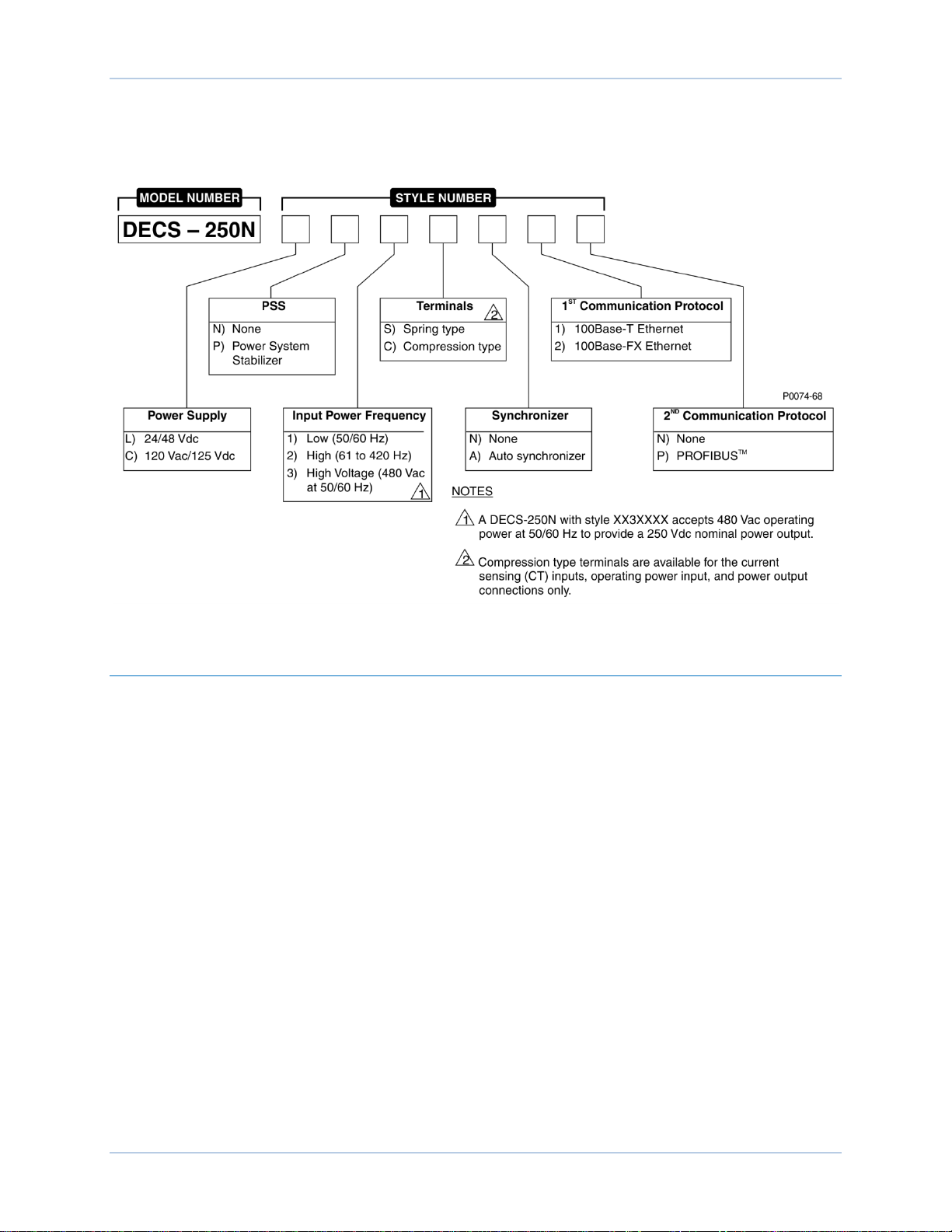
9440500990 Rev C 3
Style Number
The style number identification chart in Figure 1 defines the electrical characteristics and operational
features available in the DECS-250N.
Figure 1. DECS-250N Style Chart
Storage
If a DECS-250N will not be placed in service right away, store it in the original shipping carton in a
moisture- and dust-free environment. The temperature of the storage environment must be within the
range of –40 to 85°C (–40 to 185°F).
Electrolytic Capacitor Considerations
The DECS-250N contains long-life aluminum electrolytic capacitors. For a DECS-250N kept in storage as
a spare, the life of these capacitors can be maximized by energizing the device for 30 minutes once per
year. Refer to the energizing procedures provided in Maintenance.
DECS-250N Introduction
Page 20

4 9440500990 Rev C
Introduction DECS-250N
Page 21
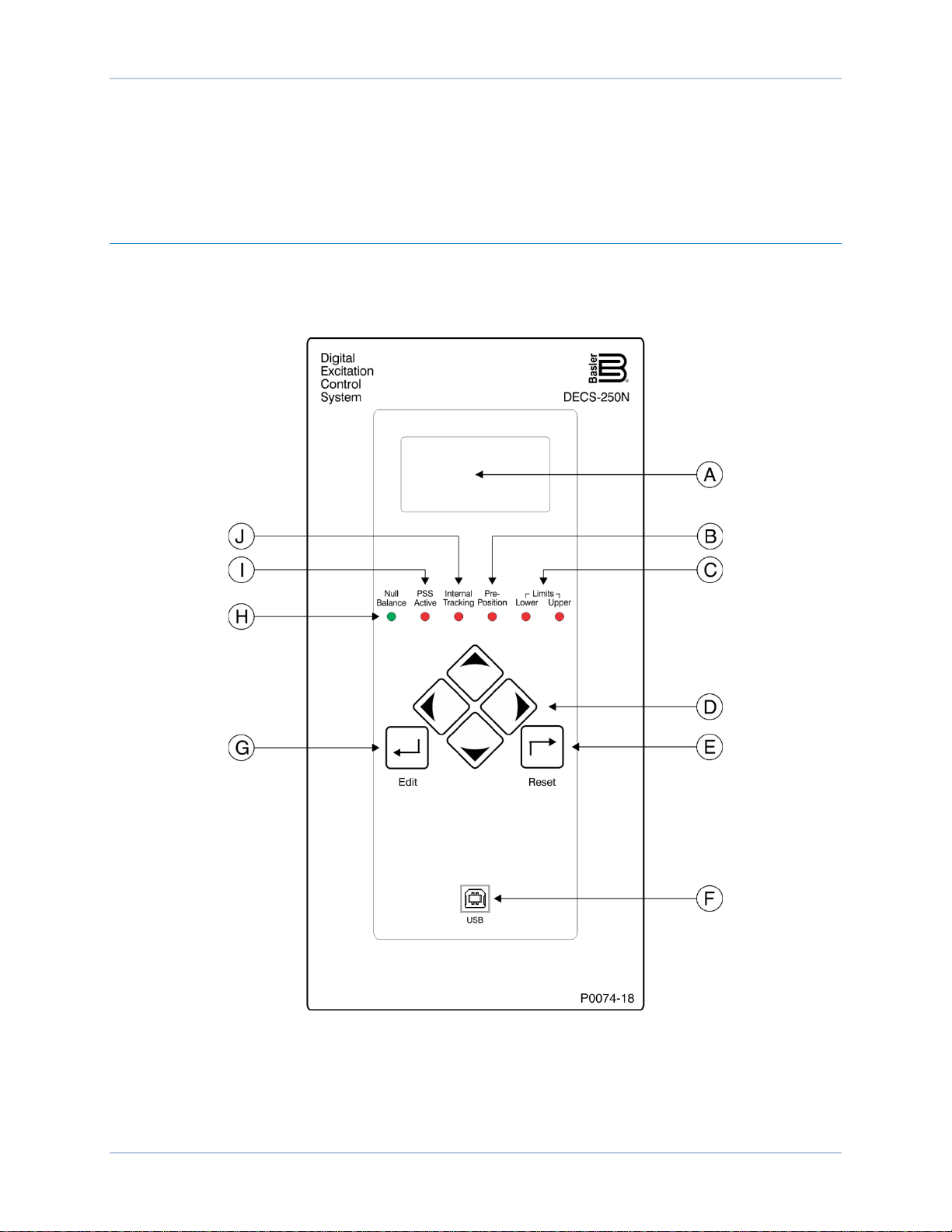
9440500990 Rev D 5
Controls and Indicators
All controls and indicators are located on the front panel and consist of pushbuttons, LED indicators, and
a liquid-crystal display (LCD).
Front Panel Illustration and Description
DECS-250N controls and indicators are illustrated in Figure 2 and described in Table 1. The locators and
descriptions of Table 1 correspond to the locators shown in Figure 2.
Figure 2. Front Panel Controls and Indicators
DECS-250N Controls and Indicators
Page 22

6 9440500990 Rev D
Locator
Description
A
Display. The liquid crystal display (LCD) serves as a local source of information
64 dot pixel, backlit LCD displays white characters on a blue background.
B
Pre-Position Indicator. This red light emitting diode (LED) lights when the active mode
setpoint is at any of the three pre-position (predefined) settings.
C
Limit Indicators. Two red LEDs indicate when the active mode setpoint reaches the
minimum or maximum value.
D
Scrolling Pushbuttons. These four buttons are used to scroll up, down, left, and right
scrolling pushbuttons change the value of the variable.
E
Reset Pushbutton. This button cancels editing sessions, resets alarm annunciations
and latched alarm relays, and can be used for quick access to the metering screen.
F
Communication Port. This type B USB jack connects the DECS-250N with a PC
Caution
G
Edit Pushbutton. Pressing this button starts an editing session and enables changes to
pressed to save the settings changes.
H
Null Balance Indicator. This green LED lights when the setpoint of the inactive
mode.
I
PSS Active Indicator. This red LED lights when the integrated power system stabilizer
disturbance.
J
Internal Tracking Indicator. This red LED lights when any inactive mode (AVR, FCR,
“bumpless” transfer when changing active modes.
Table 1. Front Panel Control and Indicators Descriptions
provided by the DECS-250N. The LCD displays operating setpoints, loop gains,
metering, protection functions, system parameters, and general settings. The 128 by
through the menus displayed on the LCD (locator A). During an editing session, the left
and right scrolling pushbuttons select the variable to be changed and the up and down
operating BESTCOMSPlus® for local communication. BESTCOMSPlus is supplied
with the DECS-250N.
In accordance with the guidelines defined in USB standards, the USB
port on this device is not isolated. To prevent damage to a connected
PC or laptop, the DECS-250N must be properly tied to ground.
DECS-250N settings. At the conclusion of the editing session, the Edit pushbutton is
operating modes (AVR, FCR, FVR, var, and PF) match the setpoint of the active
is enabled and can generate a stabilizing signal in response to a power system
FVR, Var, or Power Factor) is tracking the setpoint of the active mode to achieve a
Menu Navigation
The DECS-250N provides local access to DECS-250N settings and metering values through a menu
structure displayed on the front panel LCD. An overview of the menu structure is illustrated in Figure 3.
Movement through the menu structure is achieved by pressing the four scrolling pu s hbuttons.
Controls and Indicators DECS-250N
Page 23
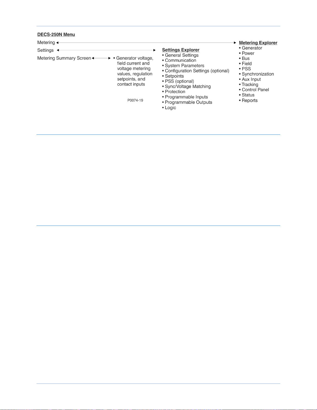
9440500990 Rev D 7
Figure 3. Menu Structure Overview
Adjusting Settings
A setting adjustment is made at the front panel by performing the following steps.
1. Navigate to the screen listing the setting to be changed.
2. Press the Edit button and enter the appropriate username and password to gain the needed level
of security access. (Information about implementing and using username and password
protection is provided in the Security chapter of this manual.)
3. Highlight the desired setting and press the Edit button to view the setting editing screen. This
screen lists the setting range or the permissible setting selection.
4. Use the scrolling pushbuttons to select the setting digits/selections and adjust/change the setting.
5. Press the Edit button to save the change.
Display Setup
BESTCOMSPlus Navigation Path: Settings Explorer, General Settings, Front Panel HMI
HMI Navigation Path: Settings, General Settings, Front Panel HMI
Front panel display appearance and behavior can be customized to meet user preferences and site
conditions. These BESTCOMSPlus settin gs are illustr a ted in Figure 4.
LCD
LCD setup includes a contrast adjustmentA to suit the viewing angle used or compensate for
environmental conditions. The ability to reverse the display colors
conditions and user preferences.
B
is provided to accommodate lighting
Sleep Mode
Sleep modeC reduces the demand on control power by turning off the LCD backlight when no pushbutton
activity is seen for the duration of the LCD Backlight Timeout setting
D
.
Language
Language modules are available for the DECS-250N. Once a language module is implemented it can be
enabled via the Language Selection sett ing
E
.
DECS-250N Controls and Indicators
Page 24
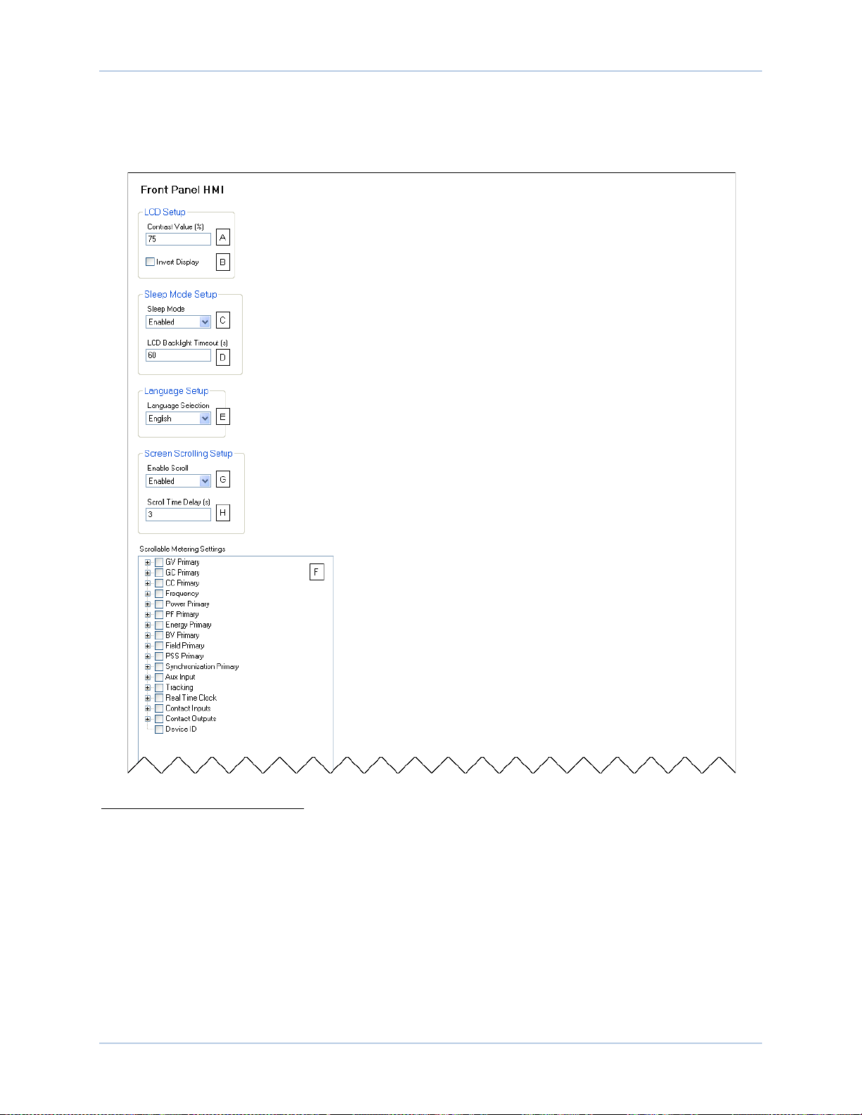
8 9440500990 Rev D
Screen Scrolling
The display can be set to automatically scroll through a user-selected listF of metered values. This feature
is enabled and disabled with the Enable Scroll setting
with the Scroll Time Delay setting
H
.
G
. The rate at which scrolling occurs is configured
Figure 4. Front Panel HMI Settings
A
Contrast Value (%): Adjustable from 0 to 100 in 1% increments.
B
Invert display: Deselect for white characters on a blue background. Select for blue characters on a white
background.
C
Sleep Mode: Enable or disable.
D
LCD Backlight Timeout: Adjustable from 0 to 120 seconds in 1 second increments.
E
Language Selection: Select English, Russian, Spanish, German, or Chinese.
F
Scrollable Metering Settings: Select from main categories of GV Primary, GC Primary, CC Primary,
Frequency, Power Primary, PF Primary, Energy Primary, BV Primary, Field Primary, PSS Primary,
Synchronization Primary, Aux Input, Tracking, Real Time Clock, Contact Inputs, Contact Outputs, or
Device ID. Follow this selection by the desired parameters within each category.
G
Enable Scroll: Enable or disable.
H
Scroll Time Delay (s): Adjustable from 1 to 600 seconds in 1 second increments.
Controls and Indicators DECS-250N
Page 25

9440500990 Rev D 9
Desired Nominal
Excitation Power Voltage
Applied Operating
Power Voltage Range
63 Vdc
100 to 139 Vac
125 Vdc
190 to 277 Vac
250 Vdc
380 to 528 Vac, 50/60 Hz (style xx3xxxx)
DECS-250N
Style Number
Operating Power
Frequency Range
xx1xxxx
50/60 Hz
xx2xxxx
61 to 420 Hz
xx3xxxx
50/60 Hz (480 Vac input, 250 Vdc output)
Power Inputs
Power is applied to two separate inputs: control power and operating power. The control power input
supplies power to an internal power supply that provides power for logic, protection, and control functions.
The power stage uses the operating power input as the source for the converted excitation power that it
applies to the field.
Control Power
Two inputs supply the DECS-250N with control power. One input accepts dc control power and the other
input accepts ac control power. The level of acceptable control power voltage is determined by the style
number. One of two levels is possible. Style Lxxxxxx indicates a nominal voltage of 24 or 48 Vdc and
accepts a voltage range of 16 to 60 Vdc. Style Cxxxxxx indicates a nominal voltage of 120 Vac/125 Vdc
and accepts a voltage range of 90 to 150 Vdc and 82 to 132 Vac (50/60 Hz). One input (either dc or ac) is
sufficient for operation but two inputs provide redundancy (for style Cxxxxxx only). When both control
power inputs are used, an isolation trans former is required for the ac input. DC control power is applied at
terminals BATT+ and BATT–. AC control power is applied at terminals L and N.
Operating Power
Operating power is applied at terminals A, B, and C. To achieve the desired level of excitation, the
appropriate operating power input voltage must be applied. Table 2 lists the acceptable operating power
voltage ranges for the DECS-250N. The operating power frequency range for the DECS-250N is listed in
Table 3.
Table 2. DECS-250N Operating Power Specifications
Table 3. DECS-250N Operating Power Frequency Specifications
DECS-250N Power Inputs
Page 26

10 9440500990 Rev D
Power Inputs DECS-250N
Page 27

9440500990 Rev D 11
Power Stage
The DECS-250N supplies regulated dc excitation power to the field of a brushless exciter. Excitation
power is supplied at terminals F+ and F–.
DECS-250N power stage operating power accepts single- or thr ee-phase ac power from a transformer or
PMG. Power stage operating power is applied at terminals A, B, and C. The GND terminal serves as a
ground connection.
The DECS-250N power stage employs a six-SCR, full-wave bridge that converts the ac operating power
input into dc excitation power. It is capable of two-quadrant operation; it can produce negative as well as
positive output power as long as positive current is flowing in the machine field (in excess of the minimum
holding current required for the SCRs). The DECS-250N power stage is capable of supplying 20 Adc
continuously at nominal voltages of 63, 125, or 250 Vdc.
Nominal DECS-250N operating power levels include 480 Vac for a 250 Vdc continuous exciter field
requirement (style XX3XXXX), 240 Vac for a 125 Vdc requirement, or 120 Vac for a 63 Vdc requirement.
The frequency range of the operating power voltage is determined by the DECS-250N style number. Style
XX1XXXX indicates an operating power frequency of 50 to 60 hertz, style XX2XXXX indicates a
frequency of 61 to 420 hertz, and style XX3XXXX limits the frequency to 50 or 60 hertz (for an operating
voltage of 480 Vac).
Field Transient Protec t ion
Fault conditions such as generator overloading or loss of synchronism can induce transients into the field
circuit. If this energy is not dissipated, it has the poten t ial to dam age the pow er stage SCRs. The
DECS-250N has two modes of field transient protection.
Most voltage transients are less than 150 microseconds in duration and are limited to a safe level by
internal DECS-250N components.
During major system faults, an SCR crowbar circuit protects the DECS-250N power stage. When field
overvoltage is detected, the power stage SCR firing pulses are blocked, the crowbar circuit is energized,
and a crowbar annunciation is made. During a normal shutdown, the same actions are taken but no
crowbar annunciation is made.
Inverting Style Excitation System Compatibility
The DECS-250N power stage can be configured for operation in the negative direction to supply the
control windings of an inverting style excitation system.
DECS-250N Power Stage
Page 28

12 9440500990 Rev D
Power Stage DECS-250N
Page 29
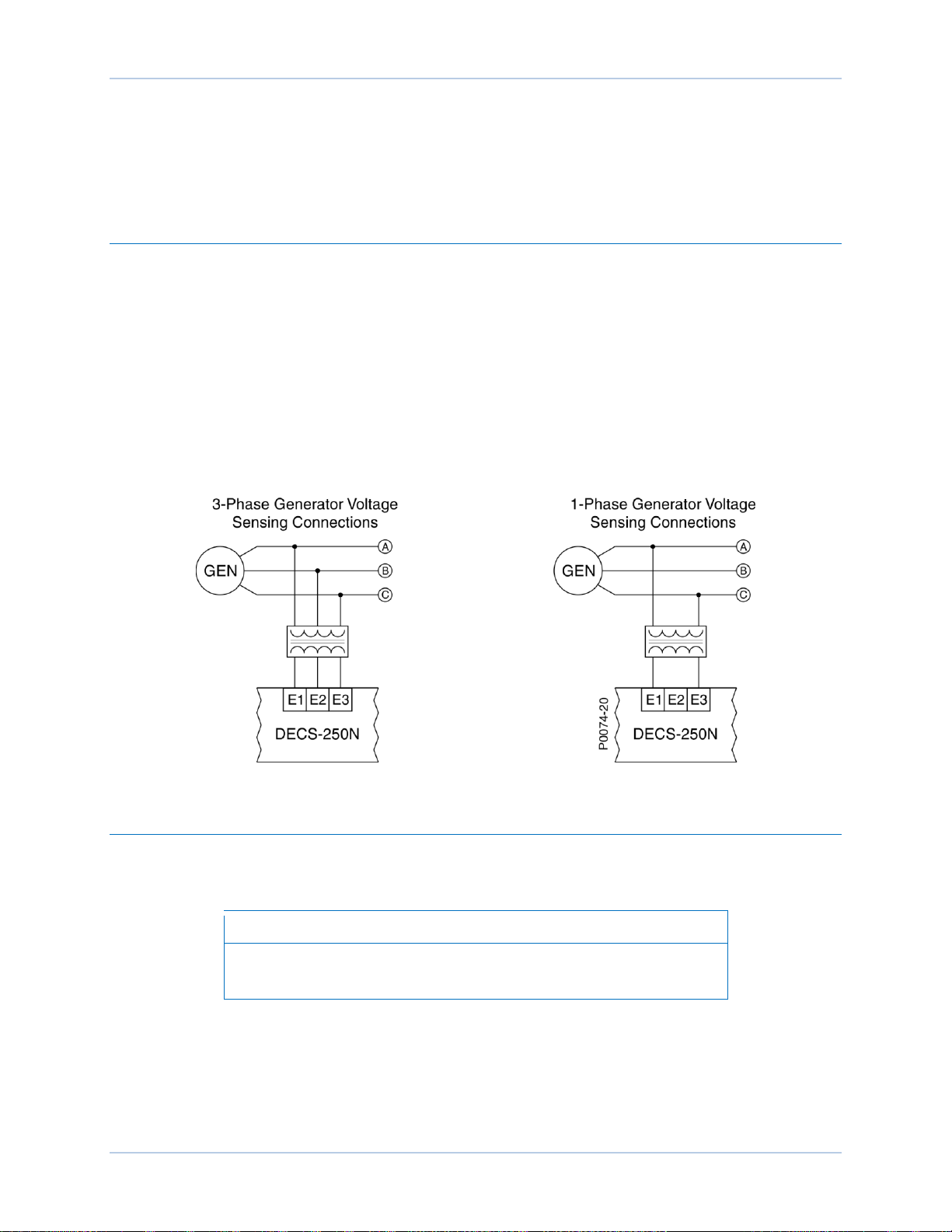
9440500990 Rev D 13
Note
Voltage and Current Sensing
The DECS-250N senses generator voltage, generator current, and bus voltage through dedicated,
isolated inputs.
Generator Voltage
Three-phase generator sensing voltage is applied to DECS-250N terminals E1, E2, and E3. This sensing
voltage is typically applied through a user-supplied voltage transformer, but may be applied directly.
These terminals accept three-phase, three-wire connections at terminals E1 (A), E2 (B), and E3 (C) or
single-phase connections at E1 (A) and E3 (C).
The generator voltage sensing input accepts a maximum voltage of 600 Vac and has a burden of less
than 1 VA.
The transformer primary and secondary winding voltages are entered in settings that the DECS-250N
uses to interpret the applied sensing voltage and calculate system parameters. The phase rotation of the
generator sensing voltage can be configured as ABC or ACB. Information about configuring the
DECS-250N for the generator sensing voltage is provided in the Configuration chapter of this manual.
Typical generator voltage sensing connections are illustrated in Figure 5.
Figure 5. Typical Generator Voltage Sensing Connections
Generator Current
Generator current sensing inputs consist of three phase-sensing inputs and a sensing input for crosscurrent compensation.
Current transformer (CT) grounding should be applied in accordance
with local codes and conventions.
Phase Sensing
Three-phase generator sensing current is applied to DECS-250N terminals CTA+ and CTA–, CTB+ and
CTB–, and CTC+ and CTC– through user-supplied current transformers (CTs). Single-phas e gen erat or
sensing current is applied to DECS-250N terminals CTB+ and CTB–. The DECS-250N is compatible with
CTs having 5 Aac or 1 Aac nominal secondary ratings. The DECS-250N uses this secondary rating, along
with the CT nominal primary ratings to interpret the sensed current and calculate system parameters.
DECS-250N Voltage and Current Sensing
Page 30
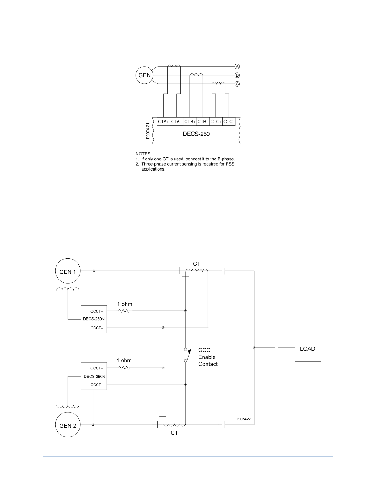
14 9440500990 Rev D
Information about configuring the DECS-250N the generator sensing voltage is provided in the
Configuration chapter of this manual. Typical generator phase-current sensing connections are shown in
Figure 6.
Figure 6. Typical Generator Current Sensing Connections
Cross-Current Compensation
Cross-current compensation (reactive differential) mode allows two or more paralleled generators to
share a common load. As shown in Figure 7, each generator is controlled by a DECS-250N using the
DECS-250N cross-current compensation input (terminals CCCT+ and CCCT–) and a dedicated, external
current transformer (CT) to sense generator current. The resistors shown in Figure 7 are used to set the
burden and may be adjusted to suit the application. Ensure that the power rating of the resistors is
adequate for the application.
Figure 7. Connections for Cross-Current Compensation
Voltage and Current Sensing DECS-250N
Page 31

9440500990 Rev D 15
Note
If a machine is taken offline, then the secondary winding of that
machine’s cross-current compensation CT must be shorted.
Otherwise, the cross-current compensation scheme will not function.
Bus Voltage
Bus voltage monitoring enables bus failure detection, generator and bus voltage matching, and
synchronization of the generator with the utility/bus. These features are discussed in the Synchronizer
chapter of this manual. Three-phase bus sensing voltage is applied to DECS-250N terminals B1, B2, and
B3. This sensing voltage is typically applied through a user-supplied voltage transformer, but may be
applied directly. These terminals accept three-phase, three-wire connections at terminals B1 (A), B2 (B),
and B3 (C) or single-phase connections at B3 (C) and B1 (A).
The bus voltage sensing input accepts a maximum voltage of 600 Vac and has a burden of less than 1
VA.
The transformer primary and secondary winding voltages are entered in settings that the DECS-250N
uses to interpret the applied sensing voltage. Information about configuring the DECS-250N for the bus
sensing voltage is provided in the Configuration chapter of this manual.
Typical bus voltage sensing connections are illustrated in Figure 8.
Figure 8. Typical Bus Voltage Sensing Connections
DECS-250N Voltage and Current Sensing
Page 32

16 9440500990 Rev D
Voltage and Current Sensing DECS-250N
Page 33

9440500990 Rev D 17
Slip Error
= Max (-)
Slip Error
=
Max (+)
Slip Error = 0
P0064-49
Synchronizer
DECS-250N controllers with a style number of xxxxAxx are equipped with an automatic synchronizer that
acts to align the voltage, phase angle, and frequency of the generator with the bus. The synchronizer
function includes compensation settings for the generator breaker and bias control settings for the
generator governor. Related synchronizer features include voltage matching and bus condition detection.
Generator Synchroniza t ion
BESTCOMSPlus Navigation Path: Settings Explorer, Synchronizer/Voltage Matching, Synchronizer
HMI Navigation Path: Settings, Sync/Voltage Matching, Synchronizer
A
Two modes of generator synchronization are available: phase lock loop and anticipatory
the DECS-250N matches the voltage, phase angle, and frequency of the generator with the bus and then
connects the generator to the bus by closing the generator breaker. Anticipatory mode has the added
capability of compensating for the breaker closing time. (Breaker closing time is the delay between the
issuance of a breaker close command and closure of the breaker contacts.) The DECS-250N
compensates for the breaker closure time by monitoring the frequency difference between the generator
and bus and calculating the advance phase angle required to close the breaker at a zero-degree phase
angle.
. In either mode,
Frequency Correction
Generator frequency correction is defined by the slip frequency and further refined by the breaker closing
angle. The slip frequency setting
(frequency) from the bus frequency. The Min Slip Control Limit setting
are used to calculate the slip frequency error and to provide continuous slip frequency control while in
phase lock synchronization. If the slip frequency magnitude is above the Max Slip Control Limit, the error
is set equal to the Max Error in the opposite polarity. If the slip frequency magnitude is below the Min Slip
Control Limit, the error is set equal to the Max Error in the opposite polarity. Whe n it is betw een the two
limits, the error is zero (0). Slip frequency error is shown in Figure 9.
To minimize the impact on the bus during synchronization, the generator frequency can be forced to
exceed the bus frequency
the generator frequency higher than the bus frequency before closing the breaker. The breaker closing
angle setting
breaker closure to be considered, the slip angle must remain within this setting for the duration of the sync
activation delay
F
defines the maximum allowable phase angle difference between the generator and bus. For
G
.
B
establishes the maximum allowable deviation of the generator speed
E
at the moment of breaker closure. If this is the case, the DECS-250N will drive
C
and Max Slip Control Limit settingD
Figure 9. Slip Frequency Error
Voltage Correction
Voltage correction is initiated when the generator voltage is outside the defined voltage window. The
voltage window setting
generator voltage surrounding the bus voltage where breaker closure will be considered. Enabling the
Vgen>Vbus setting
prior to synchronizing. A generator to bus PT matching level
up or step-down transformers in the system. The DECS-250N adjusts the sensed generator voltage by
H
is expressed as a percentage of the bus voltage and determines the band of
I
causes the DECS-250N to drive the generator voltage higher than the bus voltage
J
setting is provided to compensate for step-
DECS-250N Synchronizer
Page 34

18 9440500990 Rev D
𝐺−(𝐵+ 𝐴)= 𝑆𝑙𝑖𝑝 𝐴𝑛𝑔𝑙𝑒
this percentage. This setting also appears on the Voltage Matching screen, below. When the value is
changed, it is reflected in both places.
Angle Compensation
An angle compensationK setting is provided to offset phase shift caused by transformers in the system.
The angle compensation value is added only to the bus angle. For example, it is given that the generator
and bus are synchronized but the DECS-250N metered slip angle reads –30°. Equation 1, below,
illustrates the DECS-250N slip angle calcul ati on. This means that the gen er ator a ngl e is laggin g behi nd
the bus angle by 30° due to transformer phase shift. To compensate for this phase shift, the angle
compensation setting should contain a value of 330°. This value is added to the metered bus angle
resulting in an adjusted slip angle of zero degrees. Only the metered bus angle is affected by the angle
compensation setting, the metered generator angle is not biased by the DECS-250N.
Equation 1. DECS-250N Metered Slip Angle
Where:
G = metered generator angle
B = metered bus angle
A = angle compensation value
Failure of Synchronization
Generator synchronization is aborted if generator synchronization fails to occur within a timeframeL
established by the user.
BESTCOMSPlus
A
Sync Type: Select Anticipatory or Phase Lock Loop.
B
Slip Frequency: Adjustable from 0.1 to 0.5 Hz in 0.05 Hz increments.
C
Min Slip Control Limit: Adjustable from 0.1 to 2.0 Hz in 0.1 Hz increments .
D
Max Slip Control Limit: Adjustable from 0.1 to 2.0 Hz in 0.1 Hz increments.
E
Fgen>Fbus: Select Enable or Disable.
F
Breaker Closing Angle: Adjustable from 3 to 20° in 0.5° increments.
G
Sync Activation Delay: Adjustable from 0.1 to 0.8 s in 0.1 s increments.
H
Voltage Window: Adjustable from 2 to 15% in 0.5% increments.
I
Vgen>Vbus: Select Enable or Disable.
J
Gen to Bus PT Match Level: Adjustable from 0 to 700% in 0.1% increm ents .
®
generator synchronization settings are illustrated in Figure 10.
Figure 10. Generator Synchronizer Settings
Synchronizer DECS-250N
Page 35

9440500990 Rev D 19
K
Angle Compensation (°): Adjustable from 0.0 to 359.9° in 0.1° increments.
L
Sync Fail Activation Delay: Adjustable from 0.1 to 600 s in 0.1 s increments.
Voltage Matching
BESTCOMSPlus Navigation Path: Settings Explorer, Synchronizer/Voltage Matching, Voltage Matching
HMI Navigation Path: Settings, Sync/Voltage Matching, Voltage Matching
A
When enabled
setpoint to match the sensed bus voltage. Voltage matching is based on two parameters: band and
matching level.
The voltage matching band
matching to occur.
The generator to bus PT matching level
generator sensed voltage will be adjusted.
Voltage matching settings are illustrated in Figure 11.
, voltage matching is active in AVR control mode and automatically adjusts the AVR mode
B
defines the window in which the generator voltage must be for voltage
C
defines the percentage of the sensed bus voltage to which the
Figure 11. Voltage Matching Settings
A
Voltage Matching: Select Enabled to enable function.
B
Band: Adjustable from 0 to 20% in 0.1% increm ents .
C
Gen to Bus PT Match Level: Adjustable from 0 to 700% in 0.1% increm ents.
Breaker Hardware Configuration
BESTCOMSPlus Navigation Path: Settings Explorer, Synchronizer/Voltage Matching, Breaker
Hardware
HMI Navigation Path: Settings, Sync/Voltage Matching, Breaker Hardware
The DECS-250N can control and monitor a generator breaker. Breaker hardware settings are illustrated
in Figure 12.
Breaker Failure
When a close command is issued to the breaker, the DECS-250N monitors the breaker status and
annunciates a breaker failure if the breaker does not close within the time defined by the breaker close
wait delay
Generator Breaker
The DECS-250N must be configuredB with the generator breaker characteristics before the breaker can
be controlled by the DECS-250N. Breakers controlled by pulse or continuous control inputs
supported. During anticipatory-mode synchronization, if the generator breaker is serving to tie the
generator to the bus, the uses the breaker closing time
breaker. For a pulse-controlled generator breaker, the breaker open
A
. Typically, the wait delay is set to be longer than the actual breaker closing time.
D
to calculate the optimum time to close the
E
and closeF pulse times are used by
C
are
DECS-250N Synchronizer
Page 36

20 9440500990 Rev D
Caution
the DECS-250N when issuing open and close commands to the breaker. When setting the pulse times,
the open and close times should be set at or longer than the breaker closing time setting.
G
If desired, breaker closure is possible during a dead bus condition
Use caution when connecting a “dead” generator to a “dead” bus.
Undesired system damage can occur if the bus becomes energized
while a “dead” generator is connected to it.
and/or dead generator conditionH.
Figure 12. Breaker Hardware Configuration Settings
A
Breaker Close Wait Time: Adjustable from 0.1 to 600 s in 0.1 s increments.
B
Gen Breaker: Select Configured or NOT Configured.
C
Contact Type: Select Pulse or Continuous.
D
Breaker Closing Time: Adjustable from 0 to 800 ms in 5 ms increments.
E
Open Pulse Time: Adjustable from 0.01 to 5 s in 0.01 s increments. Setting is available only when
Contact Type is Pulse.
F
Close Pulse Time: Adjustable from 0.01 to 5 s in 0.01 s increments. Setting is available only when
Contact Type is Pulse.
G
Dead Bus Close: Select Disabled or Enabled.
H
Dead Gen Close Enable: Select Disabled or Enabled.
Generator and Bus Condition De t e ction
BESTCOMSPlus Navigation Path: Settings Explorer, Synchronizer/Voltage Matching, Bus Condition
Detection
HMI Navigation Path: Settings, Sync/Voltage Matching, Bus Condition Detection
The DECS-250N monitors the voltage and frequency of the generator and bus for determining when a
breaker closure is appropriate. Generator and bus condition detection settings are illustrated in Figure 13.
Synchronizer DECS-250N
Page 37

9440500990 Rev D 21
Generator Condition
A dead generator is recognized by the DECS-250N when the generator voltage decreases below the
dead generator threshold
A failed generator is recognized when the generator voltage or frequency does not meet the established
generator stability criteria for the duration of the failed generator activation delay
A
for the duration of the dead generator activation delayB.
C
. Generator stability
parameters are described in Generator Stability.
Generator Stability
Before initiating a breaker closure (tying the generator to a stable or dead bus), the generator voltage
must be stable. Several settings are used to determine generator stability. These settings include pickup
and dropout levels for overvoltage
generator stability is further controlled by a generator stability activation delay
D
, undervoltageE, overfrequencyF, and under-frequencyG. Recognition of
H
. Breaker closure is not
considered if the voltage conditions are not within the stability pickup and dropout settings for the duration
of the stability activation delay.
Bus Condition
A dead bus is recognized by the DECS-250N when the bus voltage decreases below the dead bus
threshold
A failed bus is recognized when the bus voltage or frequency does not meet the established stability
criteria for the duration of the failed bus activation delay
Stability.
I
for the duration of the dead bus activation delayJ.
K
. Bus stability parameters are described in Bus
Bus Stability
Before initiating a breaker closure (tying the generator to a live bus), the bus voltage must be stable.
Several settings are used to determine bus stability. These settings include pickup and dropout levels for
overvoltage
controlled by a bus stability activation delay
L
, undervoltageM, overfrequencyN, and underfrequencyO. Recognition of bus stability is further
P
. Breaker closure is not considered if the voltage conditions
are not within the stability pickup and dropout settings for the duration of the stability activation delay.
DECS-250N Synchronizer
Page 38

22 9440500990 Rev D
Figure 13. Generator and Bus Condition Detection Settings
A
Dead Gen Threshold: Adjustable from 0 to 600,000 Vac in 1 Vac increments.
B
Dead Gen Activation Delay: Adjustable from 0.1 to 600 s in 0.1 s increments.
C
Gen Failed Activation Delay : Adjustable from 0.1 to 600 s in 0.1 s increments.
D
Generator Stability Overvoltage Pickup and Dropout: Adjustable from 10 to 600,000 Vac in 1 Vac
increments.
E
Generator Stability Undervoltage Pickup and Dropout: Adjustable from 10 to 600,000 Vac in 1 Vac
increments.
F
Generator Stability Overfrequency Pickup and Dropout: Adjustable from 46 to 64 Hz in 0.05 Hz
increments.
G
Generator Stability Underfrequency Pickup and Dropout: Adjustable from 46 to 64 Hz in 0.05 Hz
increments.
H
Generator Stability Activation Delay: Adjustable from 0.1 to 600 s in 0.1 s increments.
Synchronizer DECS-250N
Page 39

9440500990 Rev D 23
I
Dead Bus Threshold: Adjustable from 0 to 600,000 Vac in 1 Vac increments.
J
Dead Bus Activation Delay: Adjustable from 0.1 to 600 s in 0.1 s increments.
K
Bus Failed Activation Delay : Adjustable from 0.1 to 600 s in 0.1 s increments.
L
Bus Stability Overvoltage Pickup and D ropo ut : Adjustable from 10 to 600,000 Vac in 1 Vac increments.
M
Bus Stability Undervoltage Pickup and Dropout: Adjustable from 10 to 600,000 Vac in 1 Vac increments.
N
Bus Stability Overfrequency Pickup and Dropout: Adjustable from 46 to 64 Hz in 0.05 Hz increments.
O
Bus Stability Underfrequency Pickup and Dropout: Adjustable from 46 to 64 Hz in 0.05 Hz increments.
P
Bus Stable Activation Delay : Adjustable from 0.1 to 600 s in 0.1 s increments.
Generator Governor Contr ol
BESTCOMSPlus Navigation Path: Settings Explorer, Synchronizer/Voltage Matching, Governor Bias
Control Settings
HMI Navigation Path: Settings, Sync/Voltage Matching, Governor Bias Control Settings
During synchronization, the DECS-250N adjusts the generator voltage and frequency by issuing speed
correction signals to the speed governor. Correction signals are issued in the form of DECS-250N output
contact closures. These correction signals may be either continuous or proportional
correction is selected, the correction pulses are of varying widths
B
and intervalsC. Initially, long pulses are
issued when the frequency difference between the generator and bus is large. As the correction pulses
take effect and the frequency difference becomes smaller, the correction pulse widths are proportionally
decreased.
A
. When proportional
Governor bias control settings are illustrated in Figure 14.
Figure 14. Generator Governor Control Settings
A
Bias Control Contact Type: Select Continuous Pulse or Proportional Pulse.
B
Correction Pulse Width: Adjustable from 0 to 99.9 s in 0.1 s increments.
C
Correction Pulse Interval: Adjustable from 0 to 99.9 s in 0.1 s increments.
DECS-250N Synchronizer
Page 40

24 9440500990 Rev D
Synchronizer DECS-250N
Page 41

9440500990 Rev D 25
Regulation
The DECS-250N precisely regulates the level of supplied excitation power in each of the five available
regulation modes. Stable regulation is enhanced by the automatic tracking of the active-mode setpoint by
the inactive regulation modes. Pre-position setpoints within each regulation mode enable the DECS-250N
to be configured for multiple system and application needs.
BESTCOMSPlus Navigation Path: Settings Explorer, Oper ati ng Set tings , AVR/FCR/FVR and VAR/PF
HMI Navigation Path: Settings, Operating Settings, A VR/FCR/FVR and VAR/PF
Regulation Modes
The DECS-250N provides five regulation modes: Automatic Voltage Regulation (AVR), Field Current
Regulation (FCR), Field Voltage Regulation (FVR), var, and Power Factor (PF).
AVR
When operating in AVR (Automatic Voltage Regulation) mode, the DECS-250N regulates the excitation
level in order to maintain the generator terminal voltage setpoint
A
despite changes in load and operating
conditions. AVR setpoint (or operating point) adjustment is made through:
• Application of contacts at DECS-250N contact inputs configured for raising and lowering the
active setpoint
• Application of an analog control signal at the DECS-250N Auxiliary Control input.
• The BESTCOMSPlus
®
Control Panel screen (available in the BESTCOMSPlus Metering Explorer)
• A raise or lower command transmitted through the DECS-250N Modbus port
The range of adjustment is defined by MinimumB and MaximumC settings that are expressed as a
percentage of the rated generator voltage. The length of time required to adjust the AVR setpoint from
one limit to the other is controlled by a Traverse Rate setting
D
. These settings are illustrated in Figure 15.
FCR
When operating in FCR (Field Current Regulation) mode, the DECS-250N regulates the level of current it
supplies to the field based on the FCR setpoint
field rated data and other associated settings. FCR setpoint adjustment is made through:
• Application of contacts at DECS-250N contact inputs configured for raising and lowering the
active setpoint
• Application of an analog control signal at the Auxiliary Control input
• The BESTCOMSPlus Control Panel screen (available in the BESTCOMSPlus Metering Explorer)
• A raise or lower command transmitted through the DECS-250N Modbus port
The range of adjustment is defined by Minimum
percentage of the rated field current. The length of time required to adjust the FCR setpoint from one limit
to the other is controlled by a Traverse Rate setting
E
. The setting range of the FCR setpoint depends on the
F
and MaximumG settings that are expressed as a
H
. These settings are illustrated in Figure 15.
FVR
FVR (Field Voltage Regulation) mode enables generator modeling and validation testing in accordance
with WECC testing requirements. FVR mode can also be used to smooth the transfer from the active
DECS-250N to a secondary DECS.
When operating in FVR mode, the DECS-250N regulates the level of field voltage it supplies to the field
based on the FVR setpoint
I
. The setting range of the FVR setpoint depends on the field rated data and
other associated settings. FVR setpoint adjustment is made through:
• Application of contacts at DECS-250N contact inputs configured for raising and lowering the
active setpoint
• Application of an analog control signal at the DECS-250N Auxiliary Control input
DECS-250N Regulation
Page 42

26 9440500990 Rev D
• The BESTCOMSPlus Control Panel screen (available in the BESTCOMSPlus Metering Explorer)
• A raise or lower command transmitted through the DECS-250N Modbus port
J
The range of adjustment is defined by Minimum
percentage of the rated field voltage. The length of time required to adjust the FVR setpoint from one limit
to the other is controlled by a Traverse Rate
Figure 15. AVR, FCR, and FVR Regulation Settings
A
AVR Setpoint: Range of adjustment is based on the rated generator voltage and limited by the AVR Min
(B) and Max (C) settings.
B
Min (% of rated): Adjustable from 70 to 120% in 0.1% increments.
C
Max (% of rated): Adjustable from 71 to 120% in 0.1% increments.
D
Traverse Rate (s): Adjustable from 10 to 200 seconds in 1 second increments.
E
FCR Setpoint: Range of adjustment is based on the rated field current and limited by the FCR Min (F)
and Max (G) settings.
F
Min (% of rated): Adjustable from 0 to 120% in 0.1% increments.
G
Max (% of rated): Adjusta b le fro m 0 to 120% in 0.1% inc r ements .
H
Traverse Rate (s): Adjustable from 10 to 200 seconds in 1 second increments.
I
FVR Setpoint: Range of adjustment is based on the rated field voltage and limited by the FCR Min (J)
and Max (K) settings.
J
Min (% of rated): Adjustable from 0 to 150% in 0.1% increments.
K
Max (% of rated): Adjustable from 0 to 1 50% in 0.1% i ncr ements .
L
Traverse Rate: Adjustable from 10 to 200 seconds in 1 second increment s.
and MaximumK settings that are expressed as a
L
setting. These settings are illustrated in Figure 15.
Var
When operating in var mode, the DECS-250N regulates the reactive power (var) output of the generator
based on the var setpoint
other associated settings. Var setpoint adjustment is made through:
• Application of contacts at DECS-250N contact inputs configured for raising and lowering the
active setpoint
• Application of an analog control signal at the Auxiliary Control input
• The BESTCOMSPlus Control Panel screen (available in the BESTCOMSPlus Metering Explorer)
• A raise or lower command transmitted through the DECS-250N Modbus port
The range of adjustment is defined by Minimum
percentage of the generator rated kVA output. The length of time required to adjust the Var setpoint from
one limit to the other is controlled by a Traverse Rate setting
defines the upper and lower boundaries of voltage correction when operating in var or power factor
regulation modes. Var mode setti ngs are illustr at ed in Figure 16.
A
. The setting range of the var setpoint depends on the generator ratings and
B
and MaximumC settings that are expressed as a
D
. A Fine Voltage Adjustment Band settingE
Regulation DECS-250N
Page 43

9440500990 Rev D 27
Power Factor
When operating in Power Factor (PF) mode, the DECS-250N controls the var output of the generator to
maintain the Power Factor setpoint
setpoint is determined by the PF – Leading
adjust the PF setpoint from one limit to the other is controlled by a Traverse Rate setting
Adjustment Band setting
E
defines the upper and lower boundaries of voltage correction when the
DECS-250N is operating in Var or Power Factor regulation modes. PF Active Power Leve l
F
as the kW load on the generator varies. The setting range of the PF
G
and PF – LaggingH settings. The length of time required to
I
. A Fine Voltage
J
establishes
the level of generator output power (kW) where the DECS-250N switches to/from Droop
Compensation/Power Factor mode. If the level of power decreases below the setting, the DECS-250N
switches from Power Factor mode to Droop Compensation mode. Conversely, as the level of power
increases above the setting, the DECS-250N switches from Droop Compensation mode to Power Factor
mode. A setting of 0 to 30% may be entered in 0.1% increments.
Power Factor mode settings are illustrated in Figure 16.
Figure 16. Var and Power Factor Regulation Settings
A
Setpoint: Range of adjustment is based on the generator ratings and limited by the Var Minimum (B) and
Var Maximum (C) settings.
B
Min (% of rated): Ad justable from –100 to 100% in 0.1% increments.
C
Max (% of rated): Adjusta b le fro m 0 to 100% in 0.1% inc r ements .
D
Traverse Rate (s): Adjustable from 10 to 200 seconds in 1 second increments.
E
Fine Voltage Adjustment Band: Adjustable from 0 to 30% in 0.01% increments.
F
PF Setpoint: Range of adjustment is determined by the PF Leading (G) and Lagging (H) settings.
G
PF – Leading: Adjustable f r om –1 to –0.5 in 0.005 increments.
H
PF – Lagging: Adjustable from 0.5 to 1 in 0.005 increments.
I
Traverse Rate (s): Adjustable from 10 to 200 seconds in 1 second increments.
J
PF Active Power Level: Adjust ab le from 0 to 30% in 0.1% incre ments .
Pre-Position Setpoints
Each regulation mode has three pre-position setpoints which allow the DECS-250N to be configured for
multiple system and application needs. Each pre-position setpoint can be assigned to a programmable
contact input. When the appropriate contact input is closed, the setpoint is driven to the corresponding
pre-position value. Each pre-position funct ion has two s ettings: Setpoint and Mode. The setting range of
each pre-position setpoint
setting determines whether or not the DECS-250N will respond to further setpoint change commands
while the pre-position command is being asserted. If the pre-position mode is Release, setpoint change
commands are accepted to raise and lower the setpoint whi le the pre-position command is being
asserted. Additionally, if the inactive pre-position mode is Release and internal tracking is enabled, the
pre-position value will respond to the tracking function. If the pre-position mode is Maintain, further
setpoint change commands are ignored while the appropriate contact input is closed. Additionally, if the
inactive pre-position mode is Maintain and internal tracking is enabled, the inactive mode will maintain the
A
is identical to that of the corresponding control mode setpoint. The ModeB
DECS-250N Regulation
Page 44

28 9440500990 Rev D
inactive setpoint at the pre-position value and override the tracking function. A portion of the pre-position
setpoints for var and PF modes are illustrated in Figure 17. (Pre-Position Setpoints for AVR, FCR, and
FVR modes are similar and not shown here.)
Figure 17. Pre-Position Setpoints
A
Setpoint: Range of adjustment is based on the generator ratings and limited by the Var Minimum and
Var Maximum settings.
B
Mode: Select Release or Maintain
Transient Boost
The transient excitation boosting function improves response to successive faults by providing increased
excitation support. When a simultaneous line current increase and line voltage decrease occurs, the
DECS-250N compensates by elevating the voltage setpoint above the nominal setpoint. When the line
voltage recovers, the voltage setpoint is restored to the nominal value.
A
Fault detection is controlled by a voltage threshold
setting. Fault voltage threshold is expressed as a percentage of the AVR setpoint and fault current
threshold is expressed as a percentage of the rated field current. The duration setting determines how
long a fault condition is tolerated before the setpoint is adjusted.
Setpoint adjustment is controlled by a voltage setpoint boosting level
a clearing voltage delay
F
. The setpoint boosting level is expressed as a percentage above the AVR
setpoint. Transient boost is disabled once the line voltage recovers above the clearing voltage threshold.
The clearing voltage threshold is expressed as a percentage below the AVR setpoint. The clearing
voltage delay determines how long the line voltage must exceed the clearing voltage threshold before
setpoint adjustment is terminated.
setting, a current thresholdB setting, and a durationC
D
, a clearing voltage thresholdE, and
Figure 18. Transient Boost Settings
A
Fault Voltage Threshold (%): Adjustable fr om 0.0 to 100. 0% , in 0.1% incr eme nt s .
B
Fault Current Threshold (%): Adjustable fr om 0.0 to 400. 0% , in 0.1% incr eme nt s .
C
Minimum Fault Duration (ms): Adjustab le from 0 to 1, 000 ms , in 1 ms increments.
D
Voltage Setpoint Boosting Level (%): Adjustable from 0.0 to 100.0%, in 0.1% increments.
E
Clearing Voltage Threshold (%): Adjustable from 0.0 to 50.0%, in 0.1% increments.
F
Clearing Voltage Delay (ms): Adjustable from 0 to 1,000 ms, in increments of 1 ms.
Regulation DECS-250N
Page 45

9440500990 Rev D 29
Note
Operation with Parall ele d G e ner a t ors
BESTCOMSPlus Navigation Path: Settings Explorer, O perat ing Set tin gs , Parallel/LineDrop
Compensation
HMI Navigation Path: Settings, Operating Settings, Pa ralle l/L in eDr op Com pens at i on
The DECS-250N can be used to control the excitation level of two or more generators operating in
parallel so that the generators share the reactive load. The DECS-250N can employ either droop
compensation or cross-current compensation (reactive differential) schemes for reactive load sharing. A
separate load sharing function enables each machine to share the load proportionally without incurring a
voltage and frequency droop.
Paralleled generator settings are illustrated in Figure 19 and described in the following paragraphs.
Reactive Droop Compensation
Droop compensation serves as a method of controlling reactive current when the generator is connected
in parallel with another energy source. Droop compensation utilizes the B-phase CT in single-phase
applications. When droop compensation is enabled
measured generator reactive power. The reactive droop compensation setting
percentage of the generator rated terminal voltage.
A
, the generator voltage is adjusted in proportion to the
B
is expressed as a
For droop compensation to operate, th e PAR ALLEL _E N_LM lo gic
block must be set true in BESTlogic™Plus programmable logic.
Cross-Current Compensation
Cross-current compensation (reactive differential) mode serves as a method of connecting multiple
generators in parallel to share reactive load. When reactive load is shared properly, no current is fed into
the DECS-250N cross-current compensation input (which is connected to the B-phase transformer).
Improper sharing of reactive load causes a differential current to be fed into the cross-current
compensation input. When c ros s -current compensation is enabled
respond with the proper level of regulation. The response of the DECS-250N is controlled by the crosscurrent compensation gain sett ing
D
which is expressed as a percentage of the system nominal CT setting.
C
, this input causes the DECS-250N to
Application information about cross-current compensation is available in the Voltage and Current chapter
of this manual.
Network Load Sharing
In a multiple-generator application, the load sharing function ensures equal generator reactive-power
sharing. It operates in a similar manner to cross-current compensation but without the external hardware
requirements and distance limitations. Instead of sharing load based on the CT ratio, load is shared on a
per-unit basis calculated from the generator rated data. Sharing of load information between DECS-250N
controllers is accomplished through the Ethernet port of each DECS-250N communicating over a peer-topeer network dedicated for the load sharing function. Each DECS-250N measures the reactive current of
its associated generator and broadcasts its measurement to all other DECS-250N controllers on the
network. Each DECS-250N compares its level of reactive current to the sum of all measured currents and
adjusts its excitation level accordingly.
Network load sharing implements a fading droop function based on the droop setting, washout filter gain,
and washout filter time constant. During transients, load sharing will droop according to the droop
percentage and washout filter gain settings. The droop characteristic will fade with a time constant
according to the washout filter time constant.
A Load Share ID setting identifies the DECS-250N as a load sharing unit in the network. Checking a Load
Sharing Unit number box allows any DECS-250N load shar ing units on the network with that Load Share
DECS-250N Regulation
Page 46

30 9440500990 Rev D
ID number to share load with the currently connected DECS-250N. It is not necessary for the Load Share
ID to be unique for each unit. This allows for load sharing units to be grouped.
E
Load sharing settings consist of an Enable checkbox
Washout Filter Gain
I
and Load Share IDJ settings.
and DroopF, GainG, Washout Filter Time ConstantH,
Line Drop Compensation
When enabledK, line drop compensation can be used to maintain voltage at a load located at a distance
from the generator. The DECS-250N achieves this by measuring the line current and calculating the
voltage for a specific point on the line. Line drop compensation is applied to both the real and reactive
portion of the generator line current. It is expressed as a percentage of the generator terminal voltage
L
.
Equation 2
is used to calculate the Line Drop Value.
=
×
× cos
+ ×
Equation 2. Line Drop Value
LD
V
= Line drop value (per unit)
Value
= Average voltage, metered value (per unit)
avg
LD = Line Drop % / 100
I
= Average Current, metered value (per unit)
avg
I
= Angle of phase B current (no compensation)
bang
The LD
is the per-unit value seen down the line from the synchronous machine. Equation 3 is used to
Value
determine the voltage needed to adjust for line drop.
,
=
Equation 3. Voltage Needed to Adjust for Line Drop
,
Equation 4 is used to obtain primary units.
Equation 4. Obtain Primary Units
=
,
×
The new line drop adjusted setpoint is calculated using Equation 5.
× sin
=
+
Equation 5. Line Drop Adjusted Setpoint
Refer to Figure 19 for an illustration of the Line drop compensation settings.
Regulation DECS-250N
Page 47

9440500990 Rev D 31
Figure 19. Paralleled Generators and Line Drop Compensation Settings
A
Droop Compensation Enable: Place a check in the checkbox to enable droop compensation.
B
Reactive Droop Compensation: Adjustable from 0 to +30% in 0.1% increments.
C
Cross-Current Compensation Enable: Place a check in the checkbox to enable cross-current
compensation.
D
Cross-Current Compensation Gain: Adjus tab le from –30 to +30% in 0.1% increments.
E
Load Share Enable: Place a check in the checkbox to enable load sharing.
F
Load Share Droop: Adjustable from 0 to 30% in 0.1% increments.
G
Load Share Gain: Adjus ta ble fr om 0 to 1,000 in incr e ments o f 0.01.
H
Load Share Washout Filter Time Constant: Adjustable from 0 to 1 in increments of 0.01.
I
Load Share Washout Filter Gain: Adjustable from 0 to 1,000 in increments of 0.01.
J
Load Share ID: Adjustable from 1 to 16 in increments of 1.
K
Line Drop Compensation Enable: Place a check in the checkbox to enable line drop compensation.
L
Line Drop Compensation: Adjustable from 0 to 30% in increments of 0.1%.
Autotracking
BESTCOMSPlus Navigation Path: Settings Explorer, Oper ati ng Set tings , Autotracking
HMI Navigation Path: Settings, Operating Settings, Au totr ack ing.
Internal regulation mode setpoint tracking and external setpoint tracking are standard features on the
DECS-250N. Autotracking settings are illustrated in Figure 20.
Internal Setpoint Tracking
In applications using a single DECS-250N, internal tracking can be enabledA so that the inactive
regulation modes track the active regulation mode.
DECS-250N Regulation
Page 48

32 9440500990 Rev D
Note
The following examples demonstrate the advantages of internal tracking:
• If the excitation system is operating online with internal tracking enabled, a loss of sensing condition
could trigger a transfer to FCR mode. Autotracking minimizes the impact that a loss of sensing
condition has on the exciter’s ability to maintain the proper excitation level.
• While performing routine testing of the DECS-250N in backup mode, the internal tracking feature
allows a transfer to an inactive mode that will result in no disturbance to the system.
B
Two parameters control the behavior of internal tracking. A delay setting
between large system disturbance and the start of setpoint tracking. A traverse rate setting
determines the time delay
C
configures
the length of time for the inactive mode setpoints to traverse the full setting range of the active mode
setpoint.
External Setpoint Tracking
For critical applications, a second DECS-250N can provide backup excitation control. The DECS-250N
allows for excitation redundancy by providing external tracking and transfer provisions between
DECS-250N controllers. The secondary DECS-250N can be configured to track the primary DECS-250N
setpoint. Proper redundant excitation system design allows for removal of the failed system.
Periodic testing of the backup system must be performed to ensure
that it is operational and can be placed in service without warning.
Like internal tracking, external setpoint tracking uses enable/disableD, delayE, and traverse rateF settings.
Figure 20. Autotracking Settings
A
Internal Tracking Enabled: Place a check in the checkbox to enable internal tracking.
B
Internal Tracking Delay: Adjustable from 0 to 8 seconds in 0.1 second increments.
C
Internal Tracking Traverse Rate: Adjustable from 1 to 80 seconds in 0.1 second increments.
D
External Tracking Enabled: Place a check in the checkbox to enable external tracking.
E
External Tracking Delay: Adjustable from 0 to 8 seconds in 0.1 second increments.
F
External Tracking Traverse Rate: Adjustable from 1 to 80 seconds in 0.1 second increments.
Setpoint Configure
When the Auto Save settin g is enabled, the DECS-250N automatically s aves the active setpoint in oneminute intervals. Other wise, the setpoint which was last sent to the DECS-250N is retaine d. Figure 21
illustrates the Setpoint Configure screen.
Figure 21. Setpoint Configure Setting
Regulation DECS-250N
Page 49

9440500990 Rev D 33
=
(
0.004)×
20.0
0.016
10.0
Auxiliary Control
BESTCOMSPlus Navigation Path: Settings Explorer, Oper ati ng Set tings , Auxiliary Inputs
HMI Navigation Path: Settings, Operating Settings, Auxiliary Inputs
The DECS-250N accepts an external analog control signal for auxiliary control of the regulation setpoint.
Auxiliary setpoint control is possible in all regulation modes: AVR, PF, Var, FCR, and FVR. The control
signal can also be used for limiter scaling or power system stabilizer control. Auxiliary control settings are
illustrated in Figure 22.
Auxiliary Control Input TypeA
Either a voltage or current control signal may be used for auxiliary control. Terminals I+ and I– accept a 4
to 20 mAdc signal. Terminals V+ and V– accept a –10 to +10 Vdc signal. An adjacent terminal labeled
GND provides the connection for a recommended cable shield. The input type is selected in
BESTCOMSPlus
Auxiliary Control Input Funct ionB
The analog control input can be used for auxiliary control of the regulation setpoint, as a power system
stabilizer test input, or for limiter scaling.
®
.
PSS Test Input
The auxiliary control input can be used for control of the optional power system stabilizer function during
testing and validation. More information is provided in the P ow er Sy stem Sta bi lizer chapter of this manual.
Limiter Scaling
When the auxiliary control input is configured for limiter scaling, the stator current limiter (SCL) and
overexcitation limiter (OEL) low-level values can be automatically adjusted. Automatic adjustment of the
SCL and OEL is based on six parameters: signal and scale for three points. The signal value for each
point represents the accessory input voltage. The scale value defines the limiter low level as a percentage
of rated field current for the OEL and rated stator current for the SCL. For accessory input voltages
between two of the three defined points, the low-level limiter setting is linearly adjusted between the two
scale values. Limiter settings and limiter scaling are discussed in detail in the Limiters chapter of this
manual.
Setpoint Limits
Minimum and maximum setpoint limits are observed when the With Limit box is checked.
Auxiliary Control Gains
When a current input type is selected, the input current is converted internally by the DECS-250N into a
voltage signal in the range of –10 to +10 Vdc. The DECS-250N uses the following equation when
converting the applied current into a voltage.
Equation 6. Input Current to Voltage Signal Conversion
Where: V
For setpoint control, V
If the auxiliary input is unused, all auxiliary control gains should be set to zero.
is the calculated voltage signal and I
aux
is multiplied by the appropriate regulation mode auxiliary gain setting.
aux
is the applied current in amperes.
aux
DECS-250N Auxiliary Control
Page 50

34 9440500990 Rev D
AVR Mode
In AVR mode, the auxiliary control signal is multiplied by the AVR gain settingC. The result defines the
setpoint change as a percentage of the rated generator voltage.
=
× 0.01 × ×
For example, applying +10 Vdc with an AVR gain of 1.0 raises the AVR setpoint 10% of rated generator
voltage. This example also applies to the following modes.
FCR Mode
In FCR mode, the auxiliary control signal is multiplied by the FCR gain settingD. The resulting value
relates to a percentage of the rated field current.
=
× 0.01 × ×
FVR Mode
In FVR mode, the auxiliary control signal is multiplied by the FVR gain settingE. The resulting value relates
to a percentage of the rated field voltage.
=
× 0.01 × ×
Var Mode
In var mode, the auxiliary control signal is multiplied by the Var gain settingF. The resulting value relates to
a percentage of the rated apparent power (kVA).
=
× 0.01 × × 1.7321 × × ( )
Power Factor Mode
In Power Factor mode, the auxiliary control signal is multiplied by the PF gain settingG to define the PF
setpoint change.
=
× 0.01 × ( )
Summing TypeH
The auxiliary control signal can be configured to control the inner or outer regulation control loop.
Selecting the inner loop limits auxiliary control to AVR, FCR, and FVR modes. Selecting the outer loop
limits auxiliary control to PF and Var modes.
Figure 22. Auxiliary Input Settings
Auxiliary Control DECS-250N
Page 51

9440500990 Rev D 35
A
Input Type: Select Voltage or Current.
B
Input Function: Select DECS Input, Limiter Scaling, or PSS Test Input.
C
AVR (Mode) Gain: Adjust a ble from –99 to +99 in 0.01 incr eme nts .
D
FCR (Mode) Gain: Adj us ta ble from –99 to +99 in 0.01 incr eme nts .
E
FVR (Mode) Gain: Adjusta ble fr om –99 to +99 in 0.01 incr eme nts .
F
Var (Mode) Gain: Adjustable from –99 to +99 in 0.01 increments.
G
PF (Mode) Gain: Adjustable from –99 to +99 in 0.01 increments.
H
Summing Type: Select Inner Loop or Outer Loop.
DECS-250N Auxiliary Control
Page 52

36 9440500990 Rev D
Auxiliary Control DECS-250N
Page 53

9440500990 Rev D 37
Note
Contact Inputs and Outputs
Sixteen isolated, contact sensing inputs are available for initiating DECS-250N actions. Twelve sets of
output contacts provide annunciation and control.
Contact Inputs
BESTCOMSPlus Navigation Path: Settings Explorer, Programmable Inputs, Contact Inputs
HMI Navigation Path: Not available through HMI.
Sixteen contact inputs are provided for initiating DECS-250N actions. Two of the contact inputs are fixedfunction inputs: Start and Stop. The remaining 14 contact inputs are programmable. An additional 10
contact inputs are available with the optional Contact Expansion Module (CEM-2020). Contact Basler
Electric for ordering information.
All contact inputs are compatible with dry relay/switch contacts or open-collector outputs from a PLC.
Each contact input has an isolated interrogation voltage and current of 12 Vdc at 4 mAdc. Appropriate
switches/contacts should be selected for operation with this signal level.
The length of wiring connected to each contact input terminal must not
exceed 150 feet (45.7 meters). Longer wiring lengths may allow
induced electrical noise to interfere with the recognition of contact
inputs.
Start and Stop Inputs
The Start and Stop inputs accept a momentary contact closure that enables (Start) and disables (Stop)
the DECS-250N. If the DECS-250N receives Start and Stop contact inputs simultaneously, the Stop input
takes priority. Start contact input connections are made at terminals START and COM A. Stop contact
input connections are made at terminals STOP and COM A.
Programmable Inputs
The 14 programmable inputs can be connected to monitor the status of excitation system contacts and
switches. Then, using BESTlogic™Plus programmable logic, these inputs can be used as part of a userconfigured logic scheme to control and annunciate a variety of system conditions and contingencies.
Information about using the programmable inputs in a logic scheme is provided in the BESTlogicPlus
chapter.
A
To make the programmable contact inputs easier to identify, you can assign a custom name
to the inputs/functions of your system. Figure 23 shows a portion of the BESTCOMSPlus
screen where each of the 14 inputs can be assigned a custom name.
that relates
®
Contact Inputs
DECS-250N Contact Inputs and Outputs
Page 54

38 9440500990 Rev D
Figure 23. Contact Input Label Text
A
Label Text: Enter a string of up to 64 alphanumeric characters.
See the Terminals and Connectors chapter for an illustration of the programmable input terminals.
Contact Outputs
BESTCOMSPlus Navigation Path: Settings Explorer, Programmable Outputs, Contact Outputs
HMI Navigation Path: Not available through HMI.
DECS-250N contact outputs consist of a dedicated watchdog output and 11 programmable outputs. An
additional 18 contact outputs are available with the optional Contact Expansion Module (CEM-2020H).
The optional CEM-2020 provides an additional 24 contact outputs. Contact Basler Electric for ordering
information.
Watchdog Output
This SPDT (Form C) output changes state during the following conditions:
• Control power is lost
• Normal firmware execution ceas es
• Transfer Watchdog Trip is asserted in BESTlogicPlus.
Watchdog output connections are made at terminals WTCHD1 (normally open), WTCHD (common), and
WTCHD2 (normally closed).
Programmable Outputs
The 11 programmable, normally-open contact outputs can be configured to annunciate DECS-250N
status, active alarms, active protection functions, and active limiter functions. Using BESTlogicPlus
programmable logic, these outputs can be used as part of a user-configured logic scheme to control and
annunciate a variety of system conditions and contingencies. Information about using the programmable
outputs in a logic scheme is provided in the BESTlogicPlus chapter.
A
To make the programmable contact outputs easier to identify, you can assign a custom name
that relates
to the functions of your system. Figure 24 shows the BESTCOMSPlus Contact Outputs screen where
each of the 11 outputs can be assigned a custom name.
Contact Inputs and Outputs DECS-250N
Page 55

9440500990 Rev D 39
Figure 24. Contact Output Label Text
A
Label Text: Enter a string of up to 64 alphanumeric characters.
See the Terminals and Connectors chapter for an illustration of the programmable output terminals.
Contact output electrical ratings are listed in the Specifications chapter.
DECS-250N Contact Inputs and Outputs
Page 56

40 9440500990 Rev D
Contact Inputs and Outputs DECS-250N
Page 57

9440500990 Rev D 41
n
NOMINAL
MEASURED
T
T
HzV
HzV
D
T
−=1
/
/
100××=
FST
E
DT
T
RR
Protection
The DECS-250N offers protection relating to generator voltage, frequency, power, field parameters,
rotating exciter diodes, power input failure, and generator-to-bus synchronism. Configurable protection
elements supplement this protection with additional, user-defined system parameters that have multiple
pickup thresholds per parameter. Most protection functions have two groups of settings labeled Primary
and Secondary. Two setting groups enable independent protection coordination which is selectable in
BESTlogic™Plus.
Voltage Protection
BESTCOMSPlus Navigation Path: Settings Explorer, Protection, Voltage
HMI Navigation Path: Settings, Protection, Voltage Protection
Voltage protection includes overexcitation, generator undervoltage, generator overvoltage, and loss of
sensing voltage.
Overexcitation (Volts per Hertz)
Volts per hertz protection is annunciated if the ratio of the per-unit voltage to the per-unit frequency
(volts/hertz) exceeds one of the Volts per Hertz Pickup Level
A
settings for a definite amount of timeB. If the
Volts per Hertz Pickup level is exceeded, timing will continue until the volts per hertz ratio drops below the
dropout ratio (95%). Volts per hertz protection also guards against other potentially damaging system
conditions such as a change in system voltage and reduced frequency conditions that can exceed the
system’s excitation capability.
Several volts per hertz settings enable the DECS-250N to provide flexible generator and generator stepup transformer overexcitation protection. An inverse square timing characteristic is provided through the
Inverse Time Pickup Setpoint
approximate the heating characteristic of the generator and generator step-up transformer during
overexcitation. A linear reset characteristic is provided through the Reset Dial
protection can be enabled and disable d
C
and Time DialD settings. These settings enable the DECS-250N to
E
F
without altering the pickup and time delay settings.
setting. Volts per hertz
Two sets of fixed-time, overexcitation pickup settings are available through the Definite Time Pickup #1,
#2 and Definite Time Delay #1, #2 settings.
The following equations represent the trip time and reset time for a constant V/Hz level. Volts per hertz
characteristic curves are illustrated in Figure 25 and Figure 26.
Equation 7. Trip Time Equation 8. Reset Time
Where:
= time to trip
T
T
= time to reset
T
R
= time dial trip
D
T
= time dial, reset
D
R
= elapsed time
E
T
n = curve exponent (0.5, 1, 2)
FST=full scale trip time (T
/FST =fraction of total travel toward trip that integration had progressed to. (After a trip, this value
E
T
G
)
T
will be equal to 1.)
®
BESTCOMSPlus
overexcitation settings are illustrated in Figure 27.
DECS-250N Protection
Page 58

42 9440500990 Rev D
Figure 25. V/Hz Characteristic – Time Shown on Vertical Axis
Figure 26. V/Hz Characteristic – Time Shown on Horizontal Axis
Protection DECS-250N
Page 59

9440500990 Rev D 43
Figure 27. Overexcitation Protection Settings
A
Definite Time Pickup: Adjustable from 0 or 0.5 to 6.00 in increments of 0.01.
B
Definite Time Delay: Adjustable from 0.05 to 600 seconds in increments of 0.001 seconds.
C
Inverse Time Pickup: Adjustable from 0 or 0.5 to 6.00 in increments of 0.01.
D
Time Dial: Adjustable from 0.0 to 9.9 in increments of 0.1.
E
Reset Dial: Adjustable from 0.0 to 9.9 in increments of 0.1.
F
Mode: Select Enabled or Disabled.
G
Curve Exponent: Select 0.5, 1, or 2
Generator Undervoltage
An undervoltage pickup condition occurs when the sensed generator terminal voltage decreases below
the pickup setting
pickup threshold for the duration of the time delay setting
enabled and disabled
elements in BESTlogicPlus can be used in a logic scheme to initiate corrective action in response to the
condition. BESTCOMSPlus generator undervoltage settings are illustrated in Figure 28.
A
Generator Undervoltage Pickup (V): Adjustable from 0 to 600,000 Vac in 1 Vac increments.
B
Generator Undervoltage Time Delay (s): Adjustable from 0.1 to 60 seconds in 0.1 second increments.
C
Generator Undervoltage Enable/Disable: Select Enabled or Disabled.
A
. An undervoltage trip condition occurs if the generator voltage remains below the
C
without altering the pickup and time delay settings. Undervoltage pickup and trip
B
. Generator undervoltage protection can be
Figure 28. Generator Undervoltage Protection Settings
DECS-250N Protection
Page 60

44 9440500990 Rev D
Generator Overvoltage
An overvoltage pickup condition occurs when the sensed generator terminal voltage increases above the
pickup setting
threshold for the duration of the time delay setting
disabled
A
. An overvoltage trip condition occurs if the generator voltage remains above the pickup
C
without altering the pickup and time delay settings. Overvoltage pickup and trip elements in
B
. Generator overvoltage protection can be enabled and
BESTlogicPlus can be used in a logic scheme to initiate corrective action in response to the condition.
BESTCOMSPlus generator overvoltage settings are illustrated in Figure 29.
Figure 29. Generator Overvoltage Protection Settings
A
Generator Overvoltage Pickup (V): Adjustable from 0 to 600,000 Vac in 1 Vac increments.
B
Generator Overvoltage Time Delay (s): Adjustable from 0.1 to 60 seconds in 0.1 second increments.
C
Generator Overvoltage Enable/Disable: Select Enabled or Disabled.
Loss of Sensing
The generator voltage is monitored for a loss of sensing (LOS) condition. LOS protection settings are
illustrated in Figure 30.
In the DECS-250N, a loss of sensing event is calculated using sequence components. A loss of sensing
event occurs when the positive sequence voltage drops below the balanced
AVR setpoint, or when the negative sequence voltage increases above the unbalanced
percentage of the positive sequence voltage. A delay timer
C
is started when the event occurs, delaying
A
setting percentage of the
B
setting
the alarm by a predetermined time
D
A LOS condition can be used to initiate a transfer to manual (FCR) control mode
configured in BESTlogicPlus to initiate other actions. Protection can be enabled and disabled
. It also can be
E
without
altering the individual loss of sensing settings.
LOS protection is automatically disabled when a short circuit exists. A short circuit is detected when the
measured current is greater than twice the rated current for a single-phase CT connection and when the
positive sequence current is greater than twice the rated current for a three-phase CT connection.
Figure 30. Loss of Sensing Protection Settings
Protection DECS-250N
Page 61

9440500990 Rev D 45
A
Voltage Balanced Level: Adjustable from 0 to 100% in 0.1% increments.
B
Voltage Unbalanced Level: Adjustable from 0 to 100% in 0.1% increments.
C
Time Delay: Adjustable from 0 to 30 seconds in 0.1 second increments.
D
Transfer to Manual: Select Disabled or Enabled.
E
Mode: Select Disabled or Enabled.
Frequency Protecti on
BESTCOMSPlus Navigation Path: Settings Explorer, Protection, Frequency
HMI Navigation Path: Settings, Protection, Frequency Protection 81
The frequency of the generator terminal voltage is monitored for overfrequency and under-frequency
conditions.
Overfrequency
An overfrequency condition occurs when the frequency of the generator voltage exceeds the 81O pickup
threshold
disabled
A
for the duration of the 81O time delay settingB. Overfrequency protection can be enabled and
C
without altering the pickup and time delay settings. Overfrequency pickup and trip elements in
BESTlogicPlus can be used in a logic scheme to initiate corrective action in response to the condition.
BESTCOMSPlus overfrequency settings are illustrated in Figure 31.
Figure 31. Overfrequency Protection Settings
A
Overfrequency (81O) Pickup (Hz): Adjustable from 30 to 70 hertz in 0.01 hertz increments.
B
Overfrequency (81O) Time Delay (s): Adjustable from 0.1 to 300 seconds in 0.1 second increments.
C
Overfrequency (81O) Mode: Select Disabled or Over.
Underfrequency
An underfrequency condition occurs when the frequency of the generator voltage decreases below the
81U pickup threshold
as a percentage of the rated generator voltage, can be implemented to prevent an underfrequency trip
from occurring during startup when the generator voltage is rising toward the nominal level.
Underfrequency protection can be enabled and disabled
settings. Underfrequency pickup and trip elements in BESTlogicPlus can be used in a logic scheme to
initiate corrective action in response to the condition. BESTCOMSPlus underfrequency settings are
illustrated in Figure 32.
A
for the duration of the 81U time delay settingB. A voltage inhibit settingC, expressed
D
without altering the pickup, delay, and inhibit
DECS-250N Protection
Page 62

46 9440500990 Rev D
Figure 32. Underfrequency Protection Settings
A
Underfrequency (81U) Pickup (Hz): Adjustable from 30 to 70 hertz in 0.01 hertz increments.
B
Underfrequency (81U) Time Delay (s): Adjustable from 0.1 to 300 seconds in 0.1 second increments.
C
Underfrequency (81U) Voltage Inhibit (%): Adjustable from 50 to 100% in 1% increments.
D
Underfrequency (81U) Mode: Select Disable or Under.
Power Protection
BESTCOMSPlus Navigation Path: Settings Explorer, Protection, Power
HMI Navigation Path: Settings, Protection, Power
Generator power levels are monitored to protect against reverse power flow and loss of excitation.
Reverse Power
Reverse power protection guards against reverse power flow that may result from a loss of prime mover
torque (and lead to generator motoring). A reverse power condition occurs when the flow of reverse
power exceeds the 32R pickup threshold
protection can be enabled and disable d
power pickup and trip elements in BESTlogicPlus can be used in a logic scheme to initiate corrective
action in response to the condition. BESTCOMSPlus reverse power protection settings are illustrated in
Figure 33.
Figure 33. Reverse Power Protection Settings
A
Reverse Power (32R) Pickup (%): Adjustable from 0 to 150% in 1% increments.
B
Reverse Power (32R) Time Delay (s): Adjustable from 0 to 300 seconds in 0.1 second increments.
C
Reverse Power (32R) Mode: Select Disabled or Enabled.
A
for the duration of the 32R time delayB. Reverse power
C
without altering the pickup and time delay settings. Reverse
Loss of Excitation
The loss of excitation element operates on excessive var flow into the machine, indicating abnormally low
field excitation. This element protects controlled generators as well as motors. A diagram of the 40Q
Protection DECS-250N
Page 63

9440500990 Rev D 47
pickup response is illustrated in Figure 34. BESTCOMSPlus settings are described below and shown in
Figure 35.
Generator Protection
During loss of excitation, the generator absorbs reactive power from the power system which can
overheat the stator windings. The Loss of Excitation element acts on the principal that if a generator
begins to absorb vars outside its steady-state capability curve, it has likely lost its normal excitation
supply. The element is always calibrated to the equivalent three-phase power even if the connection is
single-phase.
The Loss of Excitation element compares the reactive power to a map of the allowed reactive power as
defined by the Pickup setting. The Loss of Excitation element remains in a pickup condition until power
flow falls below the dropout ratio of 95% of the actual pickup. A time delay is recommended for tripping.
For settings well outside the generator capability curve, adding a 0.5 second time delay helps prevent
transient fault conditions. However, recovery from power system swings after a major fault may take
several seconds. Therefore, if the unit is to pick up near the steady-state capability curve of the generator,
longer time delays are recommended. See Figure 34 for details.
Motor Protection
The DECS-250N compares the real power (kW) flowing into the motor with the reactive power (kvar)
being supplied. Operation of synchronous motors drawing reactive power from the system can result in
overheating in parts of the rotor that do not normally carry current. The 40Q pickup response is shown in
Figure 34.
Figure 34. Generator Capability Curve vs. 40Q Respo nse
Pickup and Trip
A loss of excitation condition exists when the level of absorbed vars exceeds the loss of excitation (40Q)
threshold
A
for the duration of the 40Q time delayB. A time delay setting of zero (0) makes the Loss of
Excitation element instantaneous with no intentional time delay. If the pickup condition subsides before
the time delay expires, the timer and pickup are reset, no corrective action is taken, and the element is
rearmed for any other occurrences of loss of excitation.
The 40Q threshold is expressed as a percentage of the rated var flow for the machine. Loss of excitation
protection can be enabled and disable d
C
without altering the pickup and time delay settings.
BESTCOMSPlus loss of excitation settings are illustrated in Figure 35.
DECS-250N Protection
Page 64

48 9440500990 Rev D
Figure 35. Loss of Excitation Protection Settings
A
Pickup (% of rated vars): Adjustable from 0 to 150% in 1% increments.
B
Time Delay: Adjustable from 0 to 300 seconds in 0.1 second increments.
C
Mode: Select Disabled or Enabled.
Field Protection
BESTCOMSPlus Navigation Path: Settings Explorer, Protection, Field
HMI Navigation Path: Settings, Protection, Field
Field protection provided by the DECS-250N includes field overvoltage, field overcurrent, an exciter diode
monitor, and power input failure.
Field Overvoltage
A field overvoltage condition occurs when the field voltage exceeds the field overvoltage thresholdA for the
duration of the field overvoltage time delay
without altering the pickup and time delay settings. Field overvoltage pickup and trip elements in
BESTlogicPlus can be used in a logic scheme to initiate corrective action in response to the condition.
BESTlogicPlus field overvoltage setti ngs are illustr at ed in Figure 36.
Figure 36. Field Overvoltage Protection Settings
A
Field Overvoltage Pickup (V): Adjustable from 0 to 325 Vdc in 1 Vdc increments.
B
Field Overvoltage Time Delay (s): Adjustable from 0.2 to 30 seconds in 0.1 second increments.
C
Field Overvoltage Mode: Select Disabled or Enabled.
B
. Field overvoltage protection can be enabled and disabledC
Field Overcurrent
A field overcurrent condition is annunciated when the field current exceeds the field overcurrent pickup
A
for the duration of the field overcurrent time delay. Depending on the selected timing modeB, the
level
time delay can be fixed or related to an inverse function. Definite timing mode uses a fixed time delay
inverse timing mode, the time delay is shortened in relation to the level of field current above the pickup
level. The time dial
D
setting acts as a linear multiplier for the time to an annunciation. This enables the
C
. In
DECS-250N to approximate the heating characteristic of the generator and generator step-up transformer
Protection DECS-250N
Page 65

9440500990 Rev D 49
=
×
+ + ×
=
0.36 ×
(
)
1
during overexcitation. The field current must fall below the dropout ratio (95%) for the function to begin
timing to reset. The following equations are used to calculate the field overcurrent pickup and reset time
delays.
Equation 9. Inverse Field Overcurrent Pickup
Where:
= time to pick up in seconds
t
pickup
A = -95.908
B = -17.165
C = 490.864
D = -191.816
TD = time dial setting <0.1, 20>
MOP = multiple of pickup <1.03, 205>
Equation 10. Inverse Field Overcurrent Reset
Where:
Time
TD = time dial setting <0.1, 20>
MOP
Primary and secondary setting groups provide additional control for two distinct machine operating
conditions.
Field overcurrent protection can be enabled and disabled
settings. Field overcurrent pickup and trip elements in BESTlogicPlus can be used in a logic scheme to
initiate corrective action in response to the condition. BESTCOMSPlus field overcurrent settings are
illustrated in Figure 37. In BESTCOMSPlus, a plot of the field overcurrent setting curve is displayed. The
plot can display the primary or secondary setting curves.
= maximum time to reset in seconds
reset
= multiple of pickup <1.03, 205>
reset
E
without altering the pickup and time delay
DECS-250N Protection
Page 66

50 9440500990 Rev D
Figure 37. Field Overcurrent Protection Settings
A
Field Overcurrent Pickup (A): Adjustable from 0 to 22 Adc in 0.1 Adc increments.
B
Timing Mode: Select Definite Timing or Inverse Timing
C
Field Overcurrent Time Delay (s): Adjustable from 0 or 5 to 60 seconds in 0.1 second increments.
D
Field Overcurrent Time Dial: Adjustable from 0.1 to 20 in increments of 0.1.
E
Field Overcurrent Mode: Select Disabled or Enabled.
F
Inverse field overcurrent pickup curve.
G
Curve display selections.
Exciter Diode Monitor
The exciter diode monitor (EDM) monitors the condition of a brushless exciter’s power semiconductors by
monitoring the exciter field current. The EDM detects both open and shorted rotating diodes in the exciter
bridge. EDM settings are ill ustr ated in Figure 38. When implementing the EDM, it is imperative that the
user know and specify the number of poles for the exciter armature and the generator rotor. For reliable
open diode detection, the exciter to generator pole ratio
current should be no less than 1.5 Adc. A pole ratio calculator, available in BESTCOMSPlus, can be used
to calculate the pole ratio from the number of exciter armature and generator rotor poles.
A
should be 1.5 or higher and the level of field
Protection DECS-250N
Page 67

9440500990 Rev D 51
Note
If the number of poles for the exciter armature and the generator rotor
is unknown, the EDM function will still operate. However, only a
shorted diode can be detected. If the number of poles is not known, it
is best to disable all exciter open diode protection parameters. In this
situation, the generator and exciter pole parameters must be set at
zero to prevent false tripping.
An open exciter diode may not be detected if the generator frequency
and operating power frequency are the same and the DECS-250N
operating power is supplied by a single-phase source. Three-phase
operating power is recommended for reliable open diode detection.
Open diode detection will also be impaired when a permanent magnet
generator (PMG) is supplying DECS-250N operating power and the
PMG frequency is the same or lower than the generator frequency.
All of the EDM setup guidelines presented here assume that the
exciter diodes are not open or shorted at the time of setup and testing.
The EDM estimates the fundamental harmonic of the exciter field current using discrete Fourier
transforms (DFTs). The harmonic, expressed as a percentage of the field current, is then compared to the
pickup level for open diode detection
exceeds the open diode or shorted diode pickup level, then the appropriate time delay will begin. After the
time delay for the open diode
D
or shorted diodeE condition expires and if the percentage of field current
continues to exceed the open or shorted diode pickup setting, the condition is annunciated. EDM pickup
and trip elements in BESTlogicPlus c an be used in a logic scheme to initiate corrective action in response
to an open or shorted diode condition.
B
and shorted diode detectionC. If the percentage of field current
An EDM disable level setting prevents nuisance annunciations due to low excitation current or the
generator frequency being out of range. A disable level setting
shorted-diode protection when the rated field current drops below the user-defined percentage. EDM
protection can be disabled and enable d
G
by the user without altering the individual protection settings.
F
can be used to disable both open- and
Applying EDM Protection
It is especially difficult to detect open diode conditions when the number of generator and exciter poles is
unknown. For this reason, the ratio of the number of brushless exciter armature poles to the number of
generator rotor poles should be entered to ensure detection of both open and shorted diodes.
Finding the Maximum Field Ripple Current
To set the open diode pickup level and shorted diode pickup level, the maximum ripple current on the field
must be known. This can be accomplished by running the generator unloaded and at rated speed. Vary
the generator voltage from minimum to maximum while monitoring the EDM ripple level on the HMI
display. Record the highest value.
Setting the Pickup Level—Number of Generator Poles Known
Multiply the highest EDM ripple value, obtained in the preceding paragraph, by 2. The result is the open
diode pickup level setting. The multiplier can be varied between 1.5 and 5 to increase or decrease the trip
margin. However, reducing the multiplier could result in nuisance open diode indications.
Multiply the highest EDM ripple value, obtained in the preceding paragraph by 50. The result is the
shorted diode pickup level setting. The multiplier can be varied between 40 and 70 to increase or
decrease the trip margin. However, reducing the multiplier could result in nuisance shorted diode
indications.
The DECS-250N has fixed EDM inhibit levels to prevent nuisance failed-diode indications while the
generator frequency is less than 40 hertz or greater than 70 hertz. EDM operation is also inhibited when
the level of field current is below the disable level setting.
DECS-250N Protection
Page 68

52 9440500990 Rev D
Figure 38. Exciter Diode Monitor Protection Settings
A
EDM Pole Ratio: Adjustable from 0 to 10 in 0.01 increments.
B
Open Diode Pickup Level (%): Adjustable from 0 to 100% in 0.1% increments.
C
Shorted Diode Pickup Level (%): Adjustable from 0 to 100% in 0.1% increments.
D
Open Diode Delay (s): Adjustable from 10 to 60 seconds in 0.1 second increments.
E
Shorted Diode Delay (s): Adjustable from 5 to 30 seconds in 0.1 second increments.
F
Disable Level (%): Adjustable from 0 to 100% in 0.1% increments.
G
Mode: Select Disabled or Enabled.
Setting the Pickup Level—Number of Generator Poles Unknown
The DECS-250N can detect shorted diode conditions when the number of generator poles is not known.
To provide this protection, disable open diode protection, set the pole ratio at zero, and enable shorted
diode protection. Multiply the maximum EDM ripple level, obtained under Finding the Maximum Field
Ripple Current, by 30. The multiplier can be varied between 20 and 40 to increase or decrease the pickup
margin. However, reducing the multiplier could result in nuisance shorted diode indications.
Testing the EDM Settings
Start the generator from rest and increase the speed and voltage to the rated value. Load the machine to
its rating and confirm that no failed diode annunciations occur. All of the EDM setup guidelines presented
here assume that the exciter diodes were not opened or shorted at the time of setup and testing.
Power Input Failure
A power input failure condition exists when any one of the following occurs:
1-Phase Operating Power
• When operating power decreases below 50 Vac, a power input failure condition exists.
3-Phase Operating Power
• All three phases of operating power decrease below 50 Vac
• One or more phases of operating power decreases below 10 Vac
• A phase-to-phase voltage imbalance greater than 20% exists at the operating power input
The DECS-250N settings must be properly set to match the active operating power configuration. For
example, if the DECS-250N settings reflect a 3-phase power configuration but the actual operating power
configuration is 1-phase then the DECS-250N will interpret the one phase as an imbalance and set an
alarm/trip. For more information on 1- and 3-phase operating power settings see Configuration and
Specifications.
Power input failure protection can be used for PMG applicatio ns, shunt-, or PMG-powered systems. This
protection is only active in Start mode and after soft start. A time delay setting
annunciations to accommodate transient reductions/imbalances in the operating power input voltage.
Power input failure protecti on can be enabled and disabled
B
without altering the time delay setting. The
A
delays power input failure
Protection DECS-250N
Page 69

9440500990 Rev D 53
Caution
selected power input configurationC is shown as a read-only value. Power input failure pickup and trip
elements in BESTlogicPlus can be used in a logic scheme to initiate corrective action in response to the
condition. BESTCOMSPlus power input failure settings are illustrated in Figure 39.
Figure 39. Power Input Failure Protection Settings
A
Time Delay (s): Adjustable from 0 to 10 seconds in 0.1 second increments.
B
Mode: Select Disabled or Enabled.
C
Power Input Configuration: Read-only value
Sync-Check Protection
BESTCOMSPlus Navigation Path: Settings Explorer, Protection, Sync Check (25)
HMI Navigation Path: Settings, Protection, Sync Check (25)
Because the DECS-250N sync-check and automatic synchronizer
functions share internal circuitry, the sync-check function is not
available when the automatic synchronizer style option is selected.
When enabled
controlled generator with a bus/utility. During synchronizing, the 25 function compares the voltage
C
, and slip frequencyD differences between the generator and bus. When the generator/bus
angle
A
, the sync-check (25) function supervises the automatic or manual synchronism of the
B
, slip
differences fall within the setting for each parameter, the 25 status virtual output asserts. This virtual
output can be configured (in BESTlogicPlus) to assert a DECS-250N contact output. This contact output
can, in turn, enable the closure of a breaker tying the generator to the bus.
E
An angle compensation
setting is provided to offset phase shift caused by transformers in the system.
For more details on the angle compensation setting, see the Synchronizer chapter.
F
When the Gen Freq > Bus Freq
setting box is checked, the 25 status virtual output will not assert unless
the generator frequency is greater than the bus frequency. Sync-check protection settings are illustrated
in Figure 40.
DECS-250N Protection
Page 70

54 9440500990 Rev D
Figure 40. Sync-Check Protection Settings
A
Sync-Check Mode: Se lect Dis ab led or Enab led .
B
Sync-Check Voltage Difference (%): Adjustable from 0 to 50% in 0.1% increments.
C
Sync-Check Slip Angle (Degrees): Adjustable from 1 to 99° in 0.1° increments.
D
Sync-Check Slip Freq (Hz): Adjustable from 0.01 to 0.5 Hz in 0.01 Hz increments.
E
Angle Compensation (°): Adjustable from 0.0 to 359.9° in 0.1° increments.
F
Gen Freq > Bus Freq: Enable (checked) or Disable (unchecked)
Generator Frequency Less Than 10 Hertz
A Generator Below 10 Hz condition is annunciated when the generator frequency decreases below 10 Hz
or when residual voltage is low at 50/60 Hz. A Generator Below 10 Hz annunciation is automatically reset
when the generator frequency increases above 10 Hz or the residual voltage increases above the
threshold.
Configurable Protection
BESTCOMSPlus Navigation Path: Settings Explorer, Protection, Configurable Protection
HMI Navigation Path: Settings, Protection, Configurable Protection
The DECS-250N has eight configurable protection elements which can be used to supplement the
standard DECS-250N protection. BESTCOMSPlus configurable protection settings are illustrated in
Figure 41. To make the protection elements easier to identify, each element can be given a user-assigned
A
. A protection element is configured by selecting the parameterB to be monitored and then
name
establishing the operating characteristics for the element. Any one of the following parameters may be
selected.
• Analog Input 1, 2, 3, 4, 5, 6, 7, 8
• Auxiliary Input Current (mA)
• Auxiliary Input Voltage
• Bus Frequency
• Bus Voltage: V
• EDM Ripple
• Exciter Field Current
• Exciter Field Voltage
• Gen Current: I
• Gen Frequency
• Gen Power Factor
• Gen Voltage: V
, VBC, or VCA
AB
, IB, IC, or Average
A
, VBC, VCA, or Average
AB
Protection DECS-250N
Page 71

9440500990 Rev D 55
• Kilovarhours
• Kilowatthours
• Negative Sequence Current
• Negative Sequence Voltag e
• Positive Sequence Current
• Positive Sequence Voltage
• PSS Output
• RTD Input 1, 2, 3, 4, 5, 6, 7, 8
• Setpoint Position
• Thermocouple 1, 2
• Total kVA
• Total kvar
• Total kW
• Tracking Error
If an optional Analog Expansion Module (AEM-2020) is used, any one of the following analog, RTD, and
thermocouple inputs may be selected.
• Analog Input 1, 2, 3, 4, 5, 6, 7, or 8
• RTD Input 1, 2, 3, 4, 5, 6, 7, or 8
• Thermocouple 1 or 2
Protection can be always enabled or enabled only when the DECS-250N is enabled and supplying
excitation
C
. When protection is enabl ed only in Start mo de, an arm in g time delayD can be used to delay
protection following the start of excitation.
E
A hysteresis function holds the protection function active for a user-defined percentage
above/below the
pickup threshold. This prevents repeated pickups and dropouts where the monitored parameter is
hovering around the pickup threshold. For example, with a hysteresis setting of 5% on a protection
element configured to pick up at 100 Aac of A-phase generator overcurrent, the protection element would
pick up when the current rises above 100 Aac and remain picked up until the current decreases below 95
Aac.
Each of the eight configurable protection elements has four individually-adjustable thresholds. Each
threshold can be set for pickup when the monitored parameter increases above the pickup setting (Over),
pickup when the monitored parameter decreases below the pickup setting (Under), or no pickup
(Disabled)
F
. The pickup level for the monitored parameter is defined by a threshold settingG. While the
threshold setting range is broad, you must use a value within the setting range limits for the monitored
parameter. Using an out-of-limits threshold will prevent the protection element from functioning. An
activation delay
H
serves to delay a protective trip after the threshold (pickup) level is exceeded.
DECS-250N Protection
Page 72

56 9440500990 Rev D
Figure 41. Configurable Protection Settings
A
Label Text: Accepts a maximum of 16 alphanumeric characters.
B
Param Selection: Select Gen VAB, Gen VBC, Gen VCA, Gen V Average, Bus Freq, Bus VAB, Bus VBC,
Bus VCA, Gen Freq, Gen PF, KWH, kvarh, Gen IA, Gen IB, Gen IC, Gen I Average, KW Total, KVA Total,
kvar Total, EDM Ripple, Exciter Field Volta ge, Ex c iter F ield Curren t , Auxiliary Input Voltage, Auxiliary
Input Current (mA), Setpoint Position, Tracking Error, Negative Sequence Voltage, Negative Sequence
Current, Positive Sequence Voltage, Positive Sequence Current, PSS Output, Analog Input 1, Analog
Input 2, Analog Input 3, Analog Input 4, Analog Input 5, Analog Input 6, Analog Input 7, Analog Input 8,
RTD Input 1, RTD Input 2, RTD Input 3, RTD Input 4, RTD Input 5, RTD Input 6, RTD Input 7, RTD Input
8, Thermocouple 1, Thermocouple 2, Power Input, or NLS Error Percent.
C
Stop Mode Inhibit: Select Yes or No.
D
Arming Delay: Adjustable from 0 to 300 seconds in 1 second increments.
E
Hysteresis: Adjustable from 0 to 100% of the threshold setting in 0.1% increments.
F
Mode: Select Over, Under, or Disabled.
G
Threshold: Adjustable from –999,999 to +999,999 in 0.01 increments.
H
Activation Delay (s): Adjustable from 0 to 300 seconds in 1 second increments.
Protection DECS-250N
Page 73

9440500990 Rev D 57
FIELD CURRENT
TIME IN SECONDS
High
Current
Time
CONTINUOUS
P0063-09
0-10sec
Low
Current
Level
High
Current
Level
Limiters
DECS-250N limiters ensure that the controlled machine does not exceed its capabilities. Overexcitation,
underexcitation, stator current, and re ac tive pow er are limited by the DECS-250N. It also limits the
voltage during underfrequency conditions.
Overexcitation Limiter
BESTCOMSPlus Navigation Path: Settings Explorer, Operating Settings, Limiters, OEL
HMI Navigation Path: Settings, Operating Settings, Li miters, OEL
Operating in the overexcited region of a generator’s capability curve can cause excessive field current
and field winding heating. The overexcitation limiter (OEL) monitors the level of field current supplied by
the DECS-250N and limits it to prevent field overheating.
A
The OEL can be enabled
limit excitation or issue an alarm. This behav ior is configur e d in BEST logic ™Plus.
Two styles of overexcitation limiting are available in the DECS-250N: summing point or takeover.
settings are illustrated in Figure 45, Fi gure 46, and Figure 47.
Summing Point OEL
in all regulation modes. OEL behavior in manual mode can be configured to
B
OEL
Summing point overexcitation limiting compensates for field overcurrent conditions while the machine is
offline or online. Offline and online OEL behavior is dictated by two separate groups of settings. Primary
and secondary setting groups (selectable in configurable logic) provide additional control for two distinct
machine operating conditions.
Offline Operation
For offline operation, there are two levels of summing-point overexcitation limiting: low and high. Figure
42 illustrates the relationship of the high-level and low-level OEL thresholds.
Figure 42. Summing Point, Offline, Overexcitation Limiting
The offline, low-level OEL threshold is determined by the low-level settingC. When the excitation level is
below the low-level setting, no action is taken by the DECS-250N. The generator is permitted to operate
indefinitely with this level of excitation.
D
The offline, high-level OEL threshold is determined by a high level
and high timeE setting. When the
excitation level exceeds the high level setting, the DECS-250N acts to limit the excitation to the value of
the high-level setting. If this level of excitation persists for the duration of the high time setting, the DECS250N acts to limit the excitation to the value of the low-level setting.
Online Operation
For online operation, there are three levels of summing-point overexcitation limiti ng: low, med iu m, and
high. Figure 43 illustrates the relationship of the low-, medium-, and high-level OEL thresholds.
DECS-250N Limiters
Page 74

58 9440500990 Rev D
=
×
+ + ×
FIELD CURRENT
TIME IN SECONDS
High
Current
Time
0-10sec
CONTINUOUS
P0063-10
Medium
Current
Time
0-120sec
Low
Current
Level
Medium
Current
Level
High
Current
Level
Figure 43. Summing Point, Online, Overexcitation Limiting
The online, low-level OEL threshold is determined by the low-level settingF. When the excitation level is
below the low-level setting, no action is taken by the DECS-250N. The generator is permitted to operate
indefinitely with this level of excitation. When the excitation level exceeds the low-level setting for the
duration of the medium time setting, the DECS-250N acts to limit the excitation to the value of the lowlevel setting.
G
The online, medium-level OEL threshold is determined by a medium level
When the excitation level exceeds the medium level setting, the DECS-250N acts to limit the excitation to
the value of the medium-level setting. If this level of excitation persists for the duration of the high time
setting, the DECS-250N acts to limit the excitation to the value of the medium-level setting.
I
The online, high-level OEL threshold is determined by a high level
and high timeJ setting. When the
excitation level exceeds the high level setting, the DECS-250N instantaneously acts to limit the excitation
to the value of the medium-level setting.
and medium timeH setting.
OEL Voltage Dependency
K
Online OEL operation can be tailored for fault proximity by enabling
the OEL voltage dependency
function. If a fault is close to the generator, the OEL high-level setting is disabled (based upon the rate of
change) and switches to the medium-level setting. If a fault is away from the machine, all three (high,
medium, and low) settings remain active. In other words, if the rate of terminal voltage reduction exceeds
the OEL voltage dependency setting
L
, the high-level setting remains enabled. Otherwise, the high-level
setting is disabled.
Takeover OEL
Takeover overexcitation limiting limits the field current level in relation to an inverse time characteristic
similar to that shown in Figure 44. Separate curves may be selected for online and offline operation. If the
system enters an overexcitation condition, the field current is limited and forced to follow the selected
curve. The inverse time characteristic is defined by Equation 11.
Equation 11. Inverse Pickup Time Characteristic
Where:
= time to pick up in seconds
t
pickup
A = -95.908
B = -17.165
C = 490.864
D = -191.816
TD = time dial setting <0.1, 20>
MOP = multiple of pickup <1.03, 205>
Limiters DECS-250N
Page 75

9440500990 Rev D 59
=
×
(
)
1
Figure 44. Inverse Time Characteristic for Takeover OEL
Primary and secondary setting groups provide additional control for two distinct machine operating
conditions. Each mode of takeover OEL operation (offline and online) has a low-level
time dial
Once the field current decreases below the dropout level (95% of pickup), the function is reset based on
the selected reset method
O
setting.
P
. The available reset methods are inverse, integrating, and instantaneous.
M
, high-levelN, and
Using the inverse method, the OEL is reset based on time versus multiple of pickup (MOP). The lower the
field current level, the less time is required for reset. Inverse reset uses the following curve (Equation 12)
to calculate maximum reset time.
Equation 12. Inverse Reset Time Characteristic
Where:
Time
RC = reset coefficient setting
= maximum time to reset in seconds
reset
Q
<0.01, 100>
TD = time dial setting <0.1, 20>
MOP
= multiple of pickup <1.03, 205>
reset
For the integrating reset method, the reset time is equal to the pickup time. In other words, the amount of
time spent above the low level threshold is the amount of time required to reset.
Instantaneous reset has no intentional time delay.
®
In BESTCOMSPlus
, a plot of the takeover OEL setting curves is displayed. Settings enable selection of
the displayed curves. The plot can display the primary or secondary setting curves, the offline or online
settings curves, and the pick up or reset settings curves.
DECS-250N Limiters
Page 76

60 9440500990 Rev D
Figure 45. OEL Configuration Settings
Figure 46. Summing Point OEL Settings
Limiters DECS-250N
Page 77

9440500990 Rev D 61
Figure 47. Takeover OEL Settings
A
OEL Enable: Select checkbox to enable OEL.
B
OEL Mode: Select Summing Point or Takeover.
C
Summing Point OEL Offline Low Level: Adjustable from 0 to 20 Adc. The setting increment is 0.01 Adc.
D
Summing Point OEL Offline High Level: Adjustable from 0 to 40 Adc. The setting increment is 0.01 Adc.
E
Summing Point OEL Offline High Time: Adjustable from 0 to 10 s in 1 s increments.
F
Summing Point OEL Online Low Level: Adjustable from 0 to 20 Adc. The setting increment is 0.01 Adc.
G
Summing Point OEL Online Medium Level: Adjustable from 0 to 30 Adc. The setting increment is 0.01
Adc.
H
Summing Point OEL Online Medium Time: Adjustable from 0 to 120 s in 1 s increments.
I
Summing Point OEL Online High Level: Adjustable from 0 to 40 Adc for the DECS-250. The setting
increment is 0.01 Adc.
J
Summing Point OEL Online High Time: Adjustable from 0 to 10 s in 1 s increments.
K
dv/dt Enable: Check box to enable OEL voltage dependency.
L
dv/dt Level: Adjustable from –10 to 0 in 0.1 increments (per unit).
M
Takeover OEL Low Level: Adjustable from 0 to 15 Adc in increments of 0.01 Adc.
N
Takeover OEL High Level: Adjustable range varies depending on value of Low Level setting.
O
Takeover OEL Time Dial: Adjustable from 0.1 to 20 in increments of 0.1.
P
Reset Method: Select Inverse, Integrating, or Instantaneous.
Q
Reset Coefficient: Adjustable from 0.01 to 100 in incremen ts of 0.01.
F
Takeover OEL curve.
G
Curve display selections/legend.
Underexcitation Limiter
BESTCOMSPlus Navigation Path: Settings Explorer, Oper ati ng Set tings , Limiters, UEL
HMI Navigation Path: Settings, Operating Settings, Limiters, UEL
Operating a generator in an underexcited condition can cause the stator end iron to overheat. Extreme
underexcitation may lead to a loss of synchronism. The underexcitation limiter (UEL) senses the leading
var level of the generator and limits decreases in excitation to limit end-iron heating. When enabled
DECS-250N Limiters
A
, the
Page 78

62 9440500990 Rev D
Note
UEL operates in all regulation modes. UEL behavior in manual mode can be configured to limit excitation
or issue an alarm. This behavior is configured in BESTlogicPlus.
For UEL to operate, the PARALLEL_EN_LM logic block must be set
true in BESTlogicPlus programmable logic.
UEL settings are illustrated in Figure 48 and Figure 49.
Underexcitation limiting is implemented through an internally-generated UEL curve or a user-defined UEL
B
. The internally-generated curve is based on the desired reactive power limit at zero real power with
curve
respect to the generator voltage and current rating. The absorbed reactive power axis of the curve on the
UEL Custom Curve screen can be tailored
A user-defined curve can have a maximum of five points
generator characteristic by specifying the coordinates of the intended leading reactive power (kvar) limit at
the appropriate real power (kW) level.
The levels entered for the user-defined curve are defined for operation at the rated generator voltage. The
user-defined UEL curve can be automatically adjusted based on generator operating voltage by using the
UEL voltage dependency real-power exponent
based on the ratio of the generator operating voltage divided by the generator rated voltage raised to the
power of the UEL voltage dependency real-power exponent. UEL voltage dependency is further defined
by a real power filter time constant
F
that is applied to the l ow-pass filter for the real power output.
C
for your application.
D
. This curve allows the user to match a specific
E
. The user-defined UEL curve is automatically adjusted
Figure 48. UEL Configuration Settings
Limiters DECS-250N
Page 79

9440500990 Rev D 63
Figure 49. UEL Custom Curve Screen
A
UEL Configuration Enable: Check box to enable underexcitation limiter.
B
Curve Selection: Selec t Int er nal or Custo mized.
C
Internal Curve: Enter number to adjust range of y axis.
D
Custom Curve: Insert, enter, and delete curve data points as needed.
E
Real Power Exponent: Enter a value of 1 or 2.
F
Real Power Filter Time Constant: Enter a value from 0 to 20 seconds in 0.1 second increments.
Stator Current Limiter
BESTCOMSPlus Navigation Path: Settings Explorer, Oper ati ng Set tings , Limiters, SCL
HMI Navigation Path: Settings, Operating Settings, Li miters , SCL
The stator current limiter (SCL) monitors the level of stator current and limits it to prevent stator
overheating. To limit the stator current, the SCL modifies the excitation level according to the direction of
var flow into or out of the generator. Excessive stator current with leading power factor calls for increased
excitation. Excessive stator current with lagging power factor calls for reduced excitation.
A
The SCL can be enabled
announce high stator current but will not act to limit it. Primary and secondary SCR setting groups provide
additional control for two distinct machine operating conditions. Stator current limiting is provided at two
levels: low and high (see Figure 50). SCL settings are illustrated in Figure 51.
in all regulation modes. When operating in Manual mode, the DECS-250N will
DECS-250N Limiters
Page 80

64 9440500990 Rev D
Figure 50. Stator Current Limiting
Low-Level Limiting
When the stator current exceeds the low-level settingB, the DECS-250N annunciates the elevated level. If
this condition persists for the duration of the High SCL Time setting, the DECS-250N acts to limit the
current to the low-level SCL Setting. The generator is permitted to operate indefinitely at or below the lowlevel threshold.
High-Level Limiting
When the stator current exceeds the high-level settingC, the DECS-250N acts to limit the current to the
high-level value. If this level of current persists for the duration of the high-level time setting
D
, the DECS-
250N acts to limit the current to the low-level SCL setting.
Initial Delay
In the case of low- or high-level stator current limiting, the limiting function will not respond until an initial
time delay
A
Stator Current Limiter Enable: Check box to enable.
B
Low SCL Level: Adjustable from 0 to 66,000 Aac in 0.1 Aac increments.
C
High SCL Level: Adjustable from 0 to 66,000 Aac in 0.1 Aac increments.
D
High SCL Time: Adjustable from 0 to 60 s in 0.1 s increments.
E
Initial Delay: Adjustable from 0 to 10 s in 0.1 s increments.
E
expires.
Figure 51. Stator Current Limiter Settings
Limiters DECS-250N
Page 81

9440500990 Rev D 65
Var Limiter
BESTCOMSPlus Navigation Path: Settings Explorer, Oper ati ng Set tings , Limiters, var
HMI Navigation Path: Settings, Operating Settings, Li miter s, VA R
A
The var limiter can be enabled
and secondary setting groups provide additional control for two distinct machine operating conditions. The
var limiter setpoint
A delay setting
B
is expressed as a percentage of the calculated, maximum VA rating for the machine.
C
establishes a time delay between when the var threshold is exceeded and the DECS-
250N acts to limit the var flow.
Var limiter settings are illustrated in Figure 52.
A
Var Limiter Enable: Select checkbox to enable var limiter.
B
Var Limiter Setpoint: Adjustable from 0 to 200% in 0.1% increments.
C
Var Limiter Delay: Adjustable from 0 to 300 s in 0.1 s increments .
to limit the level of reactive power exported from the generator. Primary
Figure 52. Var Limiter Settings
Limiter Scaling
BESTCOMSPlus Navigation Path: Settings Explorer, Oper ati ng Set tings , Limiters, Scaling
HMI Navigation Path: Settings, Operating Settings, Li miters , Sc aling
Automatic adjustment (scaling) of the overexcitation limiter and stator current limiter is possible through
the DECS-250N auxiliary control input. Limiter scaling settings are illustrated in Figure 53. OEL and SCL
scaling may be independently enabled and disa ble d
on six parameters: signal and scale for three points (levels).
With the scaling input set to Auxiliary Input, the signal value
control input. This input can be a 4 to 20 mAdc signal applied to terminals I+ and I– or a –10 to +10 Vdc
signal applied to terminals V+ and V–. (The input type is selected in BESTCOMSPlus). See the Auxiliary
Control chapter of this manual for details.
With the scaling input set to AEM RTD #, the signal value for each point represents an AEM RTD input in
degrees Fahrenheit. See the Anal og Expansion Module chapter of the manual for details.
C
The scale value
for each point defines the limiter low level as a percent of rated field current for the OEL
and rated stator current for the SCL.
A
. Automatic adjustment of the OEL and SCL is based
B
for each point represents the auxiliary
DECS-250N Limiters
Page 82

66 9440500990 Rev D
Figure 53. Limiter Scaling Settings
A
OEL and SCL Scale Enable: Select Auxiliary Input, AEM RTD 1 to AEM RTD 8, or Disabled.
B
Signal: Adjustable from –10 to +10 in 0.01 increments when Auxiliary Input is selected.
Adjustable from –58 to +482 in increments of 1 when any AEM RTD input is selected.
C
Scale: Adjustable from 0 to 200 in increments of 0.1.
Underfrequency Limite r
BESTCOMSPlus Navigation Path: Settings Explorer, Oper ati ng Set tings , Limiters, Underfrequency
HMI Navigation Path: Settings, Operating Settings, Limiters, UEL
A
The underfrequency limiter is selectable for underfrequency limiting or volts per hertz limiting
limiters protect the generator from damage due to excessive magnetic flux resulting from low frequency
and/or overvoltage.
Underfrequency and volts per hertz limiter settings are illustrated in Figure 56.
B
If the generator frequency decreases below the corner frequency
for the selected underfrequency slopeC
(Figure 54), the DECS-250N adjusts the voltage setpoint so that the generator voltage follows the
underfrequency slope. The adjustment range of the corner frequency and slope settings enables the
DECS-250N to precisely match the operating characteristics of the prime mover and the loads being
applied to the generator.
. These
Limiters DECS-250N
Page 83

9440500990 Rev D 67
Corner Frequency
GENERATOR VOLTS
GENERATOR FREQUENCY
P0004-34.vsd
12-03-01
0 %
100 %
Nominal
10 Hz
Vo
l
ts
/H
e
r
tz
R
a
ti
o
GENERATOR VOLTS
GENERATOR FREQUENCY
P0004-33.vsd
12-03-01
0 %
110 %
Nominal
0 Hz
100 %
Figure 54. Typical Underfrequency Compensation Curve
Volts per Hertz
The volts per hertz limiter prevents the regulation setpoint from exceeding the volts per hertz ratio defined
by the underfrequency slope setting
Figure 55. Typical 1.1 PU Volts per Hertz Limiter Curve
Beside the underfrequency slope setting, volts per hertz limiter operation is determined by the high limiter
setting, low limiter setting, and time limiter setting. The high limiter setting
threshold for volts per hertz limiting, the low limiter setting
per hertz limiting, and the time limiter setting
C
. A typical volts per hertz limiter curve is illustrated in Figure 55.
D
E
F
establishes the time delay for limiting.
establishes the minimum threshold for volts
establishes the maximum
DECS-250N Limiters
Page 84

68 9440500990 Rev D
Figure 56. Underfrequency/Volts per Hertz Limiter Settings
A
Limiter Mode: Select UF Limiter or V/Hz Limiter.
B
Underfrequency Limiter Corner Frequency: Adjustable from 40 to 75 Hz in 0.1 Hz increments.
C
Underfrequency Limiter Slope: Adjustable from 0 to 3 in increments of 0.01.
D
V/Hz High Limiter: Adjustable from 0 to 3 in increments of 0.01.
E
V/Hz Low Limiter: Adjustable from 0 to 3 in increments of 0.01.
F
V/Hz Time Limiter: A djustable from 0 to 10 s in 0.2 s increments.
Limiters DECS-250N
Page 85

9440500990 Rev D 69
Metering
The DECS-250N provides comprehensive metering of internal and system conditions. These capabilities
include extensive parameter metering, status indication, reporting, and real-time metering analysis.
Metering Explorer
DECS-250N metering is accessed through the metering explorer menu on the front panel HMI or the
BESTCOMSPlus
®
metering explorer.
HMI
On the front panel HMI, the metering explorer is accessed through the Metering branch of the HMI menu.
BESTCOMSPlus®
In BESTCOMSPlus, the metering explorer is located in the upper left portion of the application window. Metering Screen Docking
A docking feature within the metering explorer allows arrangement and docking of multiple metering
screens. Clicking and dragging a metering screen tab displays a blue, transparent square, several arrow
boxes, and a tab box. These docking elements are illustrated in Figure 57.
Figure 57. Metering Screen Docking Controls
Dragging the blue square to the “up” (locator A), “right” (locator B), or “down” (locator C) arrow box places
the selected metering screen across the top, along the side, or at the bottom of the window. Once placed,
the screen’s thumbtack icon can be clicked to dock the screen on the corresponding top, right, or lower
bar. A docked screen is viewed by hovering the mouse pointer over the docked screen.
Dragging the blue square to one of the four arrow boxes (locator D) places the screen inside the selected
window according to the arrow box selected. A metering screen can be placed as a tab inside the
selected window by dropping the screen on the tab box at the center of the four arrow boxes.
DECS-250N Metering
Page 86

70 9440500990 Rev D
Dragging the blue square anywhere other than one of the arrow/tab boxes places the selected metering
screen as a floating window.
Metered Parameters
DECS-250N meterin g cate gories inclu de gen er ator, p ow er , bus, field, power system stabilizer (PSS), and
generator synchronization parameters.
Generator
BESTCOMSPlus Navigation Path: Metering Explorer, Generator
HMI Navigation Path: Metering Explorer, Generator
Metered generator parameters include the voltage (magnitude and angle), current (magnitude and angle),
and frequency. Primary- and per-unit values are available. Figure 58 illustrates the generator primaryvalues metering screen.
Figure 58. Generator Primary-Values Metering
Power
BESTCOMSPlus Navigation Path: Metering Explorer, Power
HMI Navigation Path: Metering Explorer, Power
Metered power parameters include true power (kW), apparent power (kVA), reactive power (kvar), and
machine power factor. Primary- and per-unit values are available. Accumulated watthours (positive and
negative kWh), varhours (positive and negative kvarh), and voltampere hours (kVAh) are also metered.
Figure 59 illustrates the power primary-values screen and Figure 60 illustrates the energy screen.
Metering DECS-250N
Page 87

9440500990 Rev D 71
DECS-250 Operating Mode
Generator
Motor
Positive (+)
Leading PF
Lagging PF
Negative (–)
Lagging PF
Leading PF
Figure 59. Power Primary-Values
Figure 60. Energy
When operating in motor mode, values for var and power factor will be opposite in BESTCOMSPlus and
on the front-panel HMI. See Table 4.
Table 4. Operating Mode
Sign of Vars
Bus
BESTCOMSPlus Navigation Path: Metering Explorer, Bus
HMI Navigation Path: Metering Explorer, Bus
Metered bus parameters include the voltage across phases A and B (Vab), phases B and C (Vbc),
phases A and C (Vca), and the average bus voltage. The frequency of the bus voltage is also metered.
Primary- and per-unit values are available. Figure 61 illustrates the bus primary-values metering screen.
DECS-250N Metering
Page 88

72 9440500990 Rev D
Figure 61. Bus Primary-Values Metering
Field
BESTCOMSPlus Navigation Path: Metering Explorer, Field
HMI Navigation Path: Metering Explorer, DECS Output
Metered field parameters include the field voltage (Vfd), current (Ifd), and exciter diode ripple. The exciter
diode ripple is reported by the exciter diode monitor (EDM) and is reported as a percentage of the
induced ripple in the exciter field current.
To achieve the desired level of excitation, the appropriate level of operating power input voltage must be
applied. This value is displayed as the power input voltage.
The level of excitation power supplied to the field is displayed as a percentage, with 0% being the
minimum and 100% being the maximum.
Primary- and per-unit values are available. Figure 62 illustrates the field primary-values metering screen.
Figure 62. Field Primary-Values Metering
PSS
BESTCOMSPlus Navigation Path: Metering Explorer, PSS (Power System Stabilizer)
HMI Navigation Path: Metering Explorer, PSS
Values metered by the power system stabilizer function display positive sequence voltage and current,
negative sequence voltage and current, terminal frequency deviation, compensated frequency deviation,
and the per-unit PSS output level. The PSS function on/off status is also reported. Primary- and per-unit
values are available. Figure 63 illustrates the PSS primary-values metering screen.
Metering DECS-250N
Page 89

9440500990 Rev D 73
Figure 63. PSS Primary-Values Metering
Synchronization
BESTCOMSPlus Navigation Path: Metering Explorer, Synchronization
HMI Navigation Path: Metering Explorer, Synchronizatio n
Metered generator-to-bus synchronization para meter s inc lu de the slip fr equ ency , s lip ang le, and volt age
difference. Primary- and pe r -unit values are available. Figure 64 illustrates the synchronization primaryvalues metering screen.
Figure 64. Synchronization Primary Values Metering
Auxiliary Control Input
BESTCOMSPlus Navigation Path: Metering Explorer, Aux Input
HMI Navigation Path: Metering Explorer, Aux Input
The control signal applied at the DECS-250N auxiliary cont rol inp ut is indicated on the Aux Input metering
screen (Figure 65). As configured in BESTCOMSPlus, a dc voltage or dc current signal may be applied.
Figure 65. Auxiliary Control Input Metering
Tracking
BESTCOMSPlus Navigation Path: Metering Explorer, Tracking
HMI Navigation Path: Metering Explorer, Tracking
DECS-250N Metering
Page 90

74 9440500990 Rev D
The metered setpoint tracking error between DECS-250N operating modes is displayed on the Tracking
metering screen (Figure 66). Status fields are also provided for the on/off status for internal and external
setpoint tracking. An additional status field indicates when the setpoint of an inactive operating mode
matches the metered value.
Figure 66. Tracking Metering
Control Panel
BESTCOMSPlus Navigation Path: Metering Explorer, Control Panel
HMI Navigation Path: Metering Explorer, Control Panel
The Control Panel (Figure 67) provides options for changing operating modes, selecting setpoint prepositions, fine tuning setpoints, and toggling virtual switches. The setpoints for AVR, FCR, FVR, var, and
PF are displayed, as well as Alarm status, PSS status, and Null Balance status.
Figure 67. Control Panel
Start/Stop Mode: Two indicators show the start/stop mode of the DECS-250N. In Stop mode, the Stop
indicator changes from gray to green. In Start mode the Start indicator changes from gray to green. To
select the DECS-250N Start status, click the Start button. Click the Stop button to select DECS-250N
Stop status.
AVR/Manual Mode: AVR and Manual Mode status is reported by two indicators. When the DECS-250N
is operating in AVR mode, the AVR indicator changes from gray to green. When operating in manual
mode, the manual indicator changes from gray to green. AVR mode is selected by clicking the AVR
button, manual mode is selected by clicking the Manual button.
FCR/FVR Mode: FCR and FVR mode status is reported by two indicators. When the DECS-250N is
operating in FCR mode, the FCR indicator changes from gray to green. When operating in FVR mode,
Metering DECS-250N
Page 91

9440500990 Rev D 75
the FVR indicator changes from gray to green. FCR mode is selected by clicking the FCR button. FVR
mode is selected by clicking the FVR button.
Var/PF Mode: Three indicators report whether Var mode is active, Power Factor mode is active, or
neither mode is active. When Var mode is active the var indicator changes from gray to green. When
Power Factor mode is active, the PF indicator changes from gray to green. When neither mode is active,
the Off indicator changes from gray to green. Var mode is enabled by clicking the var button. Power
Factor mode is enabled by clicking the PF button. Neither mode is enabled by clicking the Off button.
Only one mode can be enabled at any time.
Setpoint Pre-position: A control button and indicator is provided for the three setpoint pre-positions.
Clicking the Set 1 button adjusts the excitation setpoint to the Pre-position 1 value and changes the Preposition 1 indicator to green. Pre-positions 2 and 3 are selected by clicking either the Set 2 or Set 3
button.
Setpoints: Five status fields display the active setpoints for AVR mode, FCR mode, FVR mode, var
mode, and Power Factor mode. These active setpoints, represented by a yellow font, are not to be
confused with metered analog values which are represented by a green font throughout BESTCOMSPlus.
For details on operating setpoint settings, see the Regulation chapter.
Setpoint Fine Adjust: Clicking the Raise button increases the active operating setpoint. Clicking the
Lower button decreases the active operating setpoint. The raise and lower increment is a function of the
setpoint range of adjustment and the active mode traverse rate. The increments are directly proportional
to the adjustment range and inversely proportional to the traverse rate.
Alarm Status: The Alarm Status indicator changes from gray to green when there is an active alarm.
PSS Status: The PSS Status indicator changes from gray to green when the PSS is active.
Null Balance: The Null Balance indicator changes from gray to green when the setpoint of the inactive
operating modes (AVR, FCR, FVR, var, and PF) match the setpoint of the active mode.
Virtual Switches: These buttons control the open or closed status of the six virtual switches. Clicking the
Open button sets the switch to the open position and changes the switch indicator to gray. Clicking the
Close button sets the switch to the closed position and changes the switch indicator to red. A dialog will
appear asking if you are sure you want to open or close the switch.
Metering Summary
BESTCOMSPlus Navigation Path: Metering Explorer, Summary
HMI Navigation Path: Not available via HMI
All of the metering values displayed on the individual, previously-described metering screens are
consolidated on the metering summary screen. Primary- and per-unit values are available. Figure 68
illustrates the primary-values metering summary screen. The primary- and per-unit metering summary
screens are available only in BESTCOMSPlus.
DECS-250N Metering
Page 92

76 9440500990 Rev D
Figure 68. Metering Summary Screen
Status Indication
Status indication is provided for DECS-250N system functions, inputs, outputs, network load share,
configurable protection, alarms, and the real-time clock.
System Status
BESTCOMSPlus Navigation Path: Metering Explorer, Status, System Status
HMI Navigation Path: Metering Explorer, Status, System Status
When any of the system functions illustrated in Figure 69 ar e act ive, the corr es p o ndi ng ind icator changes
from gray to green. An inactive function is represented by a gray indicator.
Metering DECS-250N
Page 93

9440500990 Rev D 77
Figure 69. System Status Indication Screen
Inputs
BESTCOMSPlus Navigation Path: Metering Explorer, Status, Inputs
HMI Navigation Path: Metering Explorer, Status, Inputs
Status annunciation is provided for the DECS-250N and optional Contact Expansion Module (CEM-2020)
inputs. Annunciation is also provided for the optional Analog Expansion Module (AEM-2020) inputs .
DECS-250N Contact Inputs
Status indication for the DECS-250N’s 16 contact sensing inputs is provided on the BESTCOMSPlus
contact inputs screen illustrated in Figure 70. An indicator changes from gray to red when a closed
contact is sensed at the corresponding input.
DECS-250N Metering
Page 94

78 9440500990 Rev D
Figure 70. DECS-250N Contact Inputs Status Indication Screen
CEM-2020 Contact Inputs
The status of the 10 contact sensing inputs of the optional CEM-2020 Contact Expansion Module is
provided on the BESTCOMSPlus
®
remote contact inputs screen. See the Co ntac t Ex pansi on Mod ul e
chapter of this manual for a description and illustration of this screen.
AEM-2020 Inputs
Status annunciations for the optional AEM-2020 Analog Expansion Module’s analog, RTD, thermocouple,
and analog metering inputs are provided on the BESTCOMSPlus remote analog inputs, remote RTD
inputs, remote thermocouple inputs, and remote analog input values screens. These screens are
described and illustrated in the Analog Expansion Module chapter of this manual.
Outputs
BESTCOMSPlus Navigation Path: Metering Explorer, Status, Outputs
HMI Navigation Path: Metering Explorer, Status, Outputs
Status annunciation is provided for the DECS-250N contact outputs and optional Contact Expansion
Module (CEM-2020) contact outputs. Annunciation is also provided for the optional Analog Expansion
Module (AEM-2020) analog outputs.
DECS-250 Contact Outputs
Status indication for the DECS-250N’s Watchdog and 11 contact outputs is provided on the
BESTCOMSPlus contact outputs scr een illus trat ed in Figure 71. An indicator changes from gray to green
when the corresponding output changes state (Watchdog output) or closes (Output 1 through 11).
CEM-2020 Contact Outputs
The status of the 24 contact outputs of the optional CEM-2020 Contact Expansion Module is provided on
the BESTCOMSPlus
®
remote contact inputs screen. See the Contact Expansion Module chapter of this
manual for a description and illustration of this screen.
AEM-2020 Analog Outputs
Metering and status indications prov id ed by the option al AE M-2020 Analog Expansion Module are shown
on the BESTCOMSPlus remote analog outputs screen. This screen is described and illustrated in the
Analog Expansion Module chapter of this manual.
Metering DECS-250N
Page 95

9440500990 Rev D 79
Figure 71. DECS-250 Contact Outputs Status Indication Screen
Network Load Share
The screen shown in Figure 72 reports the error percent, reactive current, NLS average reactive current,
and number of generators online. The status indicators change from gray to green when a status is
active.
The Error percent is the deviation of the unit’s reactive current from the system average. The NLS
Average Reactive Current is the average of the reactive current of every unit in the system. Generators
Online is the number of units actively load sharing.
Figure 72. NLS Status Screen
Configurable Protection
BESTCOMSPlus Navigation Path: Metering Explorer, Status, Configurable Protection
HMI Navigation Path: Metering Explorer, Status, Configurable Protection
Trip status for the eight configurable, supplemental protection elements is annunciated on the
BESTCOMSPlus configurable protection screen (Figure 73). An indicator for each protection element’s
four trip thresholds changes from gray to green when the corresponding trip threshold is exceeded.
DECS-250N Metering
Page 96

80 9440500990 Rev D
Figure 73. Configurable Protection Indication Status Screen
Alarms
BESTCOMSPlus Navigation Path: Metering Explorer, Status, Alarms
HMI Navigation Path: Alarms automatically displayed when active
System parameters, communication links, protection functions, and remote inputs/outputs are constantly
monitored for alarm conditions. Active and previously latched alarms are listed on the front panel display
and the Alarms screen of BESTCOMSPlus. At the front panel, an inactive alarm is reset by selecting the
alarm and then pressing the Reset pushbutton. A Reset Alarms button on the Alarms screen is clicked to
clear all inactive alarms in BESTCOMSPlus. The BESTCOMSPlus Alarms screen is illustrated in Figure
74. All possible DECS-250N alarms are listed below.
Figure 74. DECS-250N Alarm Annunciation and Reset Screen
27P Protection
32 Protection
40Q
59P Protection
81O Protection
81U Protection
AEM Communication Failure
AEM Input 1 Out of Range
AEM Input 1 Threshold 1 Trip
AEM Input 1 Threshold 2 Trip
AEM Input 1 Threshold 3 Trip
AEM Input 1 Threshold 4 Trip
AEM Input 2 Out of Range
AEM Input 2 Threshold 1 Trip
AEM Input 2 Threshold 2 Trip
AEM Input 2 Threshold 3 Trip
AEM Input 2 Threshold 4 Trip
AEM Input 3 Out of Range
AEM Input 3 Threshold 1 Trip
AEM Input 3 Threshold 2 Trip
AEM Input 3 Threshold 3 Trip
AEM Input 3 Threshold 4 Trip
AEM Input 4 Out of Range
AEM Input 4 Threshold 1 Trip
AEM Input 4 Threshold 2 Trip
AEM Input 4 Threshold 3 Trip
AEM Input 4 Threshold 4 Trip
AEM Input 5 Out of Range
AEM Input 5 Threshold 1 Trip
AEM Input 5 Threshold 2 Trip
AEM Input 5 Threshold 3 Trip
AEM Input 5 Threshold 4 Trip
AEM Input 6 Out of Range
AEM Input 6 Threshold 1 Trip
AEM Input 6 Threshold 2 Trip
AEM Input 6 Threshold 3 Trip
Metering DECS-250N
Page 97

9440500990 Rev D 81
AEM Input 6 Threshold 4 Trip
AEM Input 7 Out of Range
AEM Input 7 Threshold 1 Trip
AEM Input 7 Threshold 2 Trip
AEM Input 7 Threshold 3 Trip
AEM Input 7 Threshold 4 Trip
AEM Input 8 Out of Range
AEM Input 8 Threshold 1 Trip
AEM Input 8 Threshold 2 Trip
AEM Input 8 Threshold 3 Trip
AEM Input 8 Threshold 4 Trip
AEM Output 1 Out of Range
AEM Output 2 Out of Range
AEM Output 3 Out of Range
AEM Output 4 Out of Range
CEM Communications Failure
CEM Communications Failure
CEM Hardware Mismatch
Configurable Protection 1 Threshold 1 Trip
Configurable Protection 1 Threshold 2 Trip
Configurable Protection 1 Threshold 3 Trip
Configurable Protection 1 Threshold 4 Trip
Configurable Protection 2 Threshold 1 Trip
Configurable Protection 2 Threshold 2 Trip
Configurable Protection 2 Threshold 3 Trip
Configurable Protection 2 Threshold 4 Trip
Configurable Protection 3 Threshold 1 Trip
Configurable Protection 3 Threshold 2 Trip
Configurable Protection 3 Threshold 3 Trip
Configurable Protection 3 Threshold 4 Trip
Configurable Protection 4 Threshold 1 Trip
Configurable Protection 4 Threshold 2 Trip
Configurable Protection 4 Threshold 3 Trip
Configurable Protection 4 Threshold 4 Trip
Configurable Protection 5 Threshold 1 Trip
Configurable Protection 5 Threshold 2 Trip
Configurable Protection 5 Threshold 3 Trip
Configurable Protection 5 Threshold 4 Trip
Configurable Protection 6 Threshold 1 Trip
Configurable Protection 6 Threshold 2 Trip
Configurable Protection 6 Threshold 2 Trip
Configurable Protection 6 Threshold 3 Trip
Configurable Protection 6 Threshold 4 Trip
Configurable Protection 7 Threshold 1 Trip
Configurable Protection 7 Threshold 2 Trip
Configurable Protection 7 Threshold 3 Trip
Configurable Protection 7 Threshold 4 Trip
Configurable Protection 8 Threshold 1 Trip
Configurable Protection 8 Threshold 2 Trip
Configurable Protection 8 Threshold 3 Trip
Configurable Protection 8 Threshold 4 Trip
Duplicate AEM
Duplicate CEM
Ethernet Link Lost
Exciter Open Diode
Exciter Shorted Diode
Failed to Build Up Alarm
Field Short Circuit Status
Field Short Circuit Status
Firmware Change
Generator Below 10Hz
IRIG Lost Sync
Loss of Sensing
No Logic
NTP Sync Lost
OEL
Phase Rotation Mismatch
Power Input Failure
Programmable Alarm 1 Name
Programmable Alarm 10 Name
Programmable Alarm 11 Name
Programmable Alarm 12 Name
Programmable Alarm 13 Name
Programmable Alarm 14 Name
Programmable Alarm 15 Name
Programmable Alarm 16 Name
Programmable Alarm 2 Name
Programmable Alarm 3 Name
Programmable Alarm 4 Name
Programmable Alarm 5 Name
Programmable Alarm 6 Name
Programmable Alarm 7 Name
Programmable Alarm 8 Name
Programmable Alarm 9 Name
Protection Field Over Current
Protection Field Over Voltage
RTD Input 1 Out of Range
RTD Input 1 Threshold 1 Trip
RTD Input 1 Threshold 2 Trip
RTD Input 1 Threshold 3 Trip
RTD Input 1 Threshold 4 Trip
RTD Input 2 Out of Range
RTD Input 2 Threshold 1 Trip
RTD Input 2 Threshold 2 Trip
RTD Input 2 Threshold 3 Trip
RTD Input 2 Threshold 4 Trip
RTD Input 3 Out of Range
RTD Input 3 Threshold 1 Trip
RTD Input 3 Threshold 2 Trip
RTD Input 3 Threshold 3 Trip
RTD Input 3 Threshold 4 Trip
RTD Input 4 Out of Range
RTD Input 4 Threshold 1 Trip
RTD Input 4 Threshold 2 Trip
RTD Input 4 Threshold 3 Trip
RTD Input 4 Threshold 4 Trip
RTD Input 5 Out of Range
RTD Input 5 Threshold 1 Trip
RTD Input 5 Threshold 2 Trip
RTD Input 5 Threshold 3 Trip
RTD Input 5 Threshold 4 Trip
RTD Input 6 Out of Range
RTD Input 6 Threshold 1 Trip
RTD Input 6 Threshold 2 Trip
RTD Input 6 Threshold 3 Trip
RTD Input 6 Threshold 4 Trip
DECS-250N Metering
Page 98

82 9440500990 Rev D
RTD Input 7 Out of Range
RTD Input 7 Threshold 1 Trip
RTD Input 7 Threshold 2 Trip
RTD Input 7 Threshold 3 Trip
RTD Input 7 Threshold 4 Trip
RTD Input 8 Out of Range
RTD Input 8 Threshold 1 Trip
RTD Input 8 Threshold 2 Trip
RTD Input 8 Threshold 3 Trip
RTD Input 8 Threshold 4 Trip
SCL
Thermocouple 1 Threshold 1 Trip
Thermocouple 1 Threshold 2 Trip
Thermocouple 1 Threshold 3 Trip
Thermocouple 1 Threshold 4 Trip
Thermocouple 2 Threshold 1 Trip
Thermocouple 2 Threshold 2 Trip
Thermocouple 2 Threshold 3 Trip
Thermocouple 2 Threshold 4 Trip
Transfer Watchdog Alarm
UEL
Underfrequency VHz
Unknown NLS Protocol Version
Var Limiter
Alarm Configuration
BESTCOMSPlus Navigation Path: Settings Explorer, Alarm Configuration, Alarms
Alarms are configured using BESTCOMSPlus. Customize the reporting style of each alarm by choosing
Disabled, Latching, or Non-Latching. Latching alarms are stored in nonvolatile memory and are retained
even when control power to the DECS-250N is lost. Active alarms are shown on the front pan el LCD and
in BESTCOMSPlus
until they are cleared. Non-latching alarms are cleared when control power is
removed. Disabling an alarm affects only the annunciation of the alarm and not the actual operation of the
alarm. This means that the alarm will still trip when trip conditions are met and the occurrence will appear
on the sequence of events reports.
The BESTCOMSPlus Alarm Settings screen is illustrated in Figure 75 below.
Figure 75. Alarm Settings Screen
User-Programmable Alarms
BESTCOMSPlus Navigation Path: Settings Explorer, Alarm Configuration, User Programmable Alarms
Sixteen user programmable alarms are available. User alarm labels
Programmable Alarms screen (Figure 76). If the trip condition exists for the duration of the Activation
B
, the alarm is tripped. When active, the label of a user programmable alarm is displayed on the
Delay
BESTCOMSPlus
®
Alarms screen, on the front panel display, and in the sequence of events reports.
A
are entered on the User
Metering DECS-250N
Page 99

9440500990 Rev D 83
Each alarm provides a logic output that can be connected to a physical output or other logic input using
BESTlogicPlus Programmable Logic. Refer to the BESTlogicPlus chapter for more information on setting
up alarm logic.
Figure 76. User Programmable Alarms Screen
A
Label Text: Enter a string of alphanumeric characters.
B
Activation Delay: Adjustable from 0 to 300 in 1 second increments.
Retrieving Alarm Information
Alarms are displayed in the sequence of events reports. Alarms are automatically shown on the front
panel display when active. To view active alarms using BESTCOMSPlus, use the Metering Explorer to
open the Status, Alarms screen. See the Metering chapter for more inf or mat ion .
Resetting Alarms
A BESTlogicPlus expression can be used to reset the alarms. Use the Settings Explorer within
BESTCOMSPlus to open the BESTlogicPlus Programmable Logic screen. Select the ALARM_RESET
logic block from the list of Elements. Use the drag and drop method to connect a variable or series of
variables to the Reset input. When this input is set TRUE, this element resets all active alarms. Refer to
the BESTlogicPlus chapter for more informat io n.
Real-Time Clock
BESTCOMSPlus Navigation Path: Metering Explorer, Status, Real Time Clock
HMI Navigation Path: Metering Explorer, Status, Real Time Clock
The DECS-250N time and date is displayed and adjusted on the BESTCOMSPlus Real-Time Clock
screen (Figure 77). Manual adjustment of the DECS-250N clock is made by clicking the Edit button. This
displays a window where the DECS-250N time and date can be adjusted manually or according to the
connected PC clock’s date and time.
Advanced clock settings such as time and date format, daylight saving time, network time protocol, and
IRIG are described in the Timekeeping chapter of this manual.
DECS-250N Metering
Page 100

84 9440500990 Rev D
Figure 77. Real-Time Clock Screen
Auto Export Metering
Found under the Tools menu, the auto export metering function is an automated method for saving
multiple metering data files at specific intervals over a period of time while connected to a DECS-250N.
The user specifies the Number of Exports and the Interval between each export. Enter a base filename
for the metering data and a folder in which to save. The exports are counted and the count number will be
appended to the base filename, making each filename unique. The first export is performed immediately
after clicking the Start button. Figure 78 illustrates the Auto Export Metering screen.
Figure 78. Auto Export Metering
Metering DECS-250N
 Loading...