

Page 1
INSTRUCTION MANUA L
FOR
DIGITAL EXCITATIO N CONTROL SYSTEM
DECS-100
Publication: 9287500991
Revision: M 02/15
Page 2

Page 3

INTRODUCTION
This instruction manual provides information about the operation and installation of the DECS-100 Digital
Excitation Control System. To accomplish this, the following informati on is provid ed:
• General Information and Specifications
• Controls and Indicators
• Functional Description
• Installation
• Maintenance and Troubleshooting
WARNING!
To avoid personal inj ury or equipment damage, only qualified personnel should
perform the procedures in this manual.
Lethal voltage is present at the rear pan el when t he u nit is ener gized. Rear pane l
connections should be made only when the unit is de-energized.
CAUTION
The Manual mode excitation level must be evaluated prior to enabling this
feature. If the level of excit ation current is inappr opriat e for the gener ator, sev ere
damage to the generator may occur.
Improper PID numbers will result in poor system performance or system damage.
When applying operating power for programming purposes, observe the pre-
cautions called out in Section 4, Installation, Preliminary Setup.
When programming the DECS-100 without the generator spinning, the
connections to DECS-100 terminals F+ and F– should be removed.
Before uploading a settings file, remove operating power from the DECS-100,
disconnect the field wiring from terminals F+ and F–, and re-apply operating
power to the DECS-100.
NOTE
Be sure that the DECS-100 is hard-wired to ear th gro und wit h no sma ller than 1 2
AWG copper wire attache d to the ground terminal on the rear of the unit case.
When the DECS-100 is configured in a system with other devices, it is
recommended to use a separate lead to the ground bus from each unit.
9287500991 Rev M DECS-100 Introduction i
Page 4

First Printing: March 2001
Printed in USA
© 2015 Basler Electric, Highland Illinois 62249 USA
All Rights Reserved
CONFIDENTIAL INFORMATION
of Basler Electric, Highland Illinois, USA. It is loaned for confidential use, subject
to return on request, and with the mutual understanding that it will not be used in
any manner detrimental to the interest of Basler Electric.
It is not the intent ion of th is manual to cover a ll detai ls and variat ions in eq uipment, n or does this manu al
provide data for every pos s ible c ont ing enc y regar di ng i ns tal lat ion or o per at ion . Th e av ai lab ility and des ign
of all features and options are subject to modification without notice. Should further information be
required, contact Basler Electric.
For terms of service relati ng to this product and software, see the Commercial Ter ms of Products and
Services document available at www.basler.com/terms.
BASLER ELECTRIC
12570 STATE ROUTE 143
HIGHLAND IL 62249-1074 USA
http://www.basler.com, info@basler.com
PHONE +1 618.654.2341 FAX +1 618.654.2351
ii DECS-100 Introduction 9287500991 Rev M
Page 5

REVISION HISTORY
Hardware
Version and Date
Change
E, 01/01
• Initial release
F, 05/01
• Deepened potting shell
G, 10/01
• Began supplying mou nti ng s c rew s
H, 02/02
• SIL-PADS were added between power components and the heat sinks
Added manufactur i ng origin to the rear label
J, 07/02
• Revised EEPROM
K, 02/03
• Replaced transistor Q8B1 with an improved part
L, 03/03
• Incremental improv em ents to firmw are and B ESTCOMS™
M, 01/04
• Improved flash memory retention
N, 05/05
• Redesigned current transformer
• Enhanced EMI/RF I im mun it y
O
• Version letter O not used
P, 08/06
• Updated CD-ROM supplied with unit to include English and French
language instruction manuals
Q
• Version letter Q not used
R, 04/07
• Resolved UEL issue with firmware modification
S, 05/07
• Provided German language manual on CD-ROM supplied with DECS-100
T, 07/07
• Released firmware version 2.13.XX
U, 01/08
• Improved power amplifier circuitry with more robust components
V, 03/08
• Added Setpoint Auto Save feature
W, 03/09
• Released BESTCO M S vers ion 1.0 8.X X.
X, 02/10
• Added enhancement for production testing.
Firmware
Version and Date
Change
1.09.XX, 01/01
• Initial release
1.11.XX, 07/01
• Enabled the protection function during the first 5 seconds of operation
• Established minimum voltage regulation at 30% of nominal sensing voltage
1.12.XX, 03/02
• Added register to detect CT type
2.13.XX, 07/07
• Added underexcitation limiting
• Added bus voltage matching provisions
2.14.XX, 03/08
• Added Setpoint Auto Sav e sett ing
2.14.XX, 04/14
• Maintenance release
BESTCOMS for
Version and Date
Change
1.02.XX, 02/01
• Initial Release
1.03.XX, 08/01
• Changed OEL scale from 100 to 1,000 to match the change in firmware
• Changed the default for all protection functions to enabled
The following information provides a historical summary of the changes made to the DECS-100 hardware,
firmware, and software. Th e corresponding revisions made to this i nstruction manual (9287500991) ar e
also summarized. Revisions are listed in chronological order.
•
• Added front panel Underexcitation Limiting indicator
• Modified the OEL setpoint scale factor to be compatible with BESTCOMS
version 1.03.XX
• Added the scale factor for per-unit gain
• Added takeover-style excitation limiting
Windows® OS
version 1.11.01
• Changed OEL default setting from 1 to 15
9287500991 Rev M DECS-100 Introduction iii
Page 6

BESTCOMS for
Windows® OS
Version and Date
Change
• Add support for French regional settings
1.04.XX, 04/02
• Made BESTCOMS compatible with older firmware versions
• Changed minimum Ki setpoint from 0 to 0.01
1.05.XX, 05/05
• Added underexcitation limiting capability
• Added provisions for bus voltage matching
1.06.XX, 11/07
• Added compatibility with Microsoft® Vista to BESTCOMS
1.07.XX, 03/08
• Added Setpoint Auto Sav e sett ing.
1.08.XX, 03/09
• Improved comm un icati ons with DEC S-100.
1.09.XX, 01/11
• Added Windows® 7 compatibility and improved field overvoltage shutdown.
1.09.XX, 04/14
• Added Windows® 8 compatibility
BESTCOMS for
Version and Date
Change
1.01.XX, 01/01
• Initial Release
1.02.XX, 08/01
• Added a Check for New Ve r sion button to the Contac t Basler screen
• Added version checking
1.03.XX, 04/02
• Added password protection
• Improved version checking function
NOTE
• BESTCOMS for Palm OS is compatible only with firmware versions
1.12.XX and earlier
Manual
Revision and Date
Change
—, 03/01
• Initial release
A, 03/01
• In Section 5, BESTCOMS Software for the Windows® Operating System
utility for the DECS-100 CD-ROM
B, 08/01
• Added Embedded Software subsection to Section 5, BEST COMS Software
• Corrected various minor errors throughout manual
C, 05/02
• Revised the torque specification for the mounting screws supplied with unit
illustrations were revised to accommodate software enhancements
D, 01/03
• Revised Voltage Matching Time Adjustment Range from 0 to 300 seconds
• Corrected figure number references in Sections 5 and 6
E, 03/04
• Added Operating Power Considerations During DECS-100 Programm ing to
• Corrected CT ratio setting range stated in Section 5
Palm® OS
• Added support for all regional settings
• Enabled reading of secondary CT value for units with firmware version
1.12.01 and higher
• Simplified the Analy s is scr een
• Added feature to calculate and send voltage matching reference for
different generator and bus PT ratios
• Added ability to select either summing point or takeover style OEL
• Added a date/time stamp to the “Save to File” names
and Section 6, BESTCOMS Software for the Palm OS® Platform, Step 2 of
Installing BESTCOMS was revised to reflect the addition of an auto-start
for the Windows® Operating System
• In Section 5, BESTCOMS Software for the Windows® Operating System
and Section 6, BESTCOMS Software for the Palm® OS Platform, text and
to 1 to 300 seconds throughout manual
Section 4, Installation, Preliminary Setup
• Added caution box regarding application of operating power during DECS100 programming to Section 5, BESTCOMS for Windows® OS and
iv DECS-100 Introduction 9287500991 Rev M
Section 6, BESTCOMS for Palm OS®
Page 7

Manual
Revision and Date
Change
F, 05/05
• Added material covering added UEL capability
• Revised all drawings to show new front panel with UEL indicator
• Added troubleshooting procedure for a UEL annunciation
G, 03/07
• Corrected illustration and des c riptio ns of BESTCO M S Meter ing, Operation
• Removed expired patent information
H, 05/08
• Added DNV compliance statement to manual specifications
• Added description of BESTCO MS Set poi nt Aut o Save featur e
J, 10/08
• Revised the setting ranges of control gain settings OEL KI, OEL Kg,
BESTCOMS version 1.07.01.
K, 05/11
• Revised Introduction to reflect new epoxy-potted package.
• Corrected various minor errors throughout manual
L, 07/13
• Section 1: Added maritime agency recognition.
capacitors while in storage.
M, 02/15
• Added UL recognition for UL6200.
• Minor text edits.
• Updated all illustrations of rear panel to show revised CT
• Added discussion of summing point and takeover style OEL limiting
• Revised voltage matching description to cover Maintain and Revert modes
• Corrected the hole drilling diameter shown in Figure 4-2
• Added illustration/description for using the ICRM-7 with the DECS-100
• Removed Section 6, BESTCOMS Software for the Palm® OS Platform and
moved Maintenance and Troubleshooting to Section 6
and Alarms screen, Operation tab
UEL KI, and UEL Kg from 0–1,000 to 0–300 to reflect changes made in
• Removed “(optional feature)” from note 5 of Figures 4-7 to 4-10, due to the
setpoint option now being standard.
• Added storage / electrolytic capacitors procedure to Section 6.
• Section 1: Added Power Dissipation to specifications.
• Section 4: Added maritime agency conditions of acceptability.
• Section 4: Added note box r egardi ng 24 Vdc operat ing power bei ng us ed
for programming the DECS-100.
• Section 5: Added caution box regarding PID calculations and instruction to
allow 5 seconds after sending settings or firmware to the DECS-100.
• Section 5: Added description for Derivative Gain TD.
• Section 6: Added energizing procedure for maintaining electrolytic
• Added EAC certification.
• Added ferrite clamp recommendations for CE compliant installation.
9287500991 Rev M DECS-100 Introduction v
Page 8

This page intentionally left blank .
vi DECS-100 Introduction 9287500991 Rev M
Page 9

CONTENTS
A detailed table of contents is provided at the start of each manual section. The manual sections are
ordered as follows.
SECTION 1 • GENERAL INFORMATION ................................................................................................. 1-1
SECTION 2 • HUMAN-MACHINE INTERFACE ........................................................................................ 2-1
SECTION 3 • FUNCTIONAL DESCRIPTION ............................................................................................ 3-1
SECTION 4 • INSTALLATION ................................................................................................................... 4-1
SECTION 5 • BESTCOMS™ SOFTWARE ............................................................................................... 5-1
SECTION 6 • MAINTENANCE AND TROUBLESHOOTING .................................................................... 6-1
9287500991 Rev M DECS-100 Introduction vii
Page 10

This page intentionally left blank.
viii DECS-100 Introduction 9287500991 Rev M
Page 11

SECTION 1 • GENERAL INFO RMATION
TABLE OF CONTENTS
SECTION 1 • GENERAL INFORMATION ................................................................................................ 1-1
INTRODUCTION.................................................................................................................................... 1-1
FEATURES ............................................................................................................................................ 1-1
Model and STYLE NUMBERs ............................................................................................................... 1-1
Style Number ...................................................................................................................................... 1-1
SPECIFICATIONS ................................................................................................................................. 1-2
Operating Power ................................................................................................................................ 1-2
Generator Voltage Sensing ................................................................................................................ 1-2
Generator Current Sensing ................................................................................................................ 1-2
Bus Voltage Sensing (Optional) ......................................................................................................... 1-2
Accessory Input .................................................................................................................................. 1-3
Communication Port ........................................................................................................................... 1-3
Contact Input Circuits ......................................................................................................................... 1-3
Common Alarm Output ....................................................................................................................... 1-3
Field Output ........................................................................................................................................ 1-3
AVR Operating Mode ......................................................................................................................... 1-3
FCR (Manual) Operating Mode .......................................................................................................... 1-4
Var Operating Mode (Optional) .......................................................................................................... 1-4
PF Operating Mode (Optional) ........................................................................................................... 1-4
Parallel Compensation ....................................................................................................................... 1-4
Field Overvoltage Protection .............................................................................................................. 1-4
Generator Overvoltage Protection ..................................................................................................... 1-4
Overexcitation Limiter ......................................................................................................................... 1-5
Underexcitation Limiter ....................................................................................................................... 1-5
Soft Start Function (AVR Mode Only) ................................................................................................ 1-5
Voltage Matching ................................................................................................................................ 1-5
Metering (BESTCOMS™) .................................................................................................................. 1-5
Environment ....................................................................................................................................... 1-6
Type Tests .......................................................................................................................................... 1-6
Physical .............................................................................................................................................. 1-6
Maritime Recognition .......................................................................................................................... 1-6
EAC Mark (Eurasian Conformity) ....................................................................................................... 1-6
UL Recognized Component ............................................................................................................... 1-6
CE Compliance .................................................................................................................................. 1-6
Figures
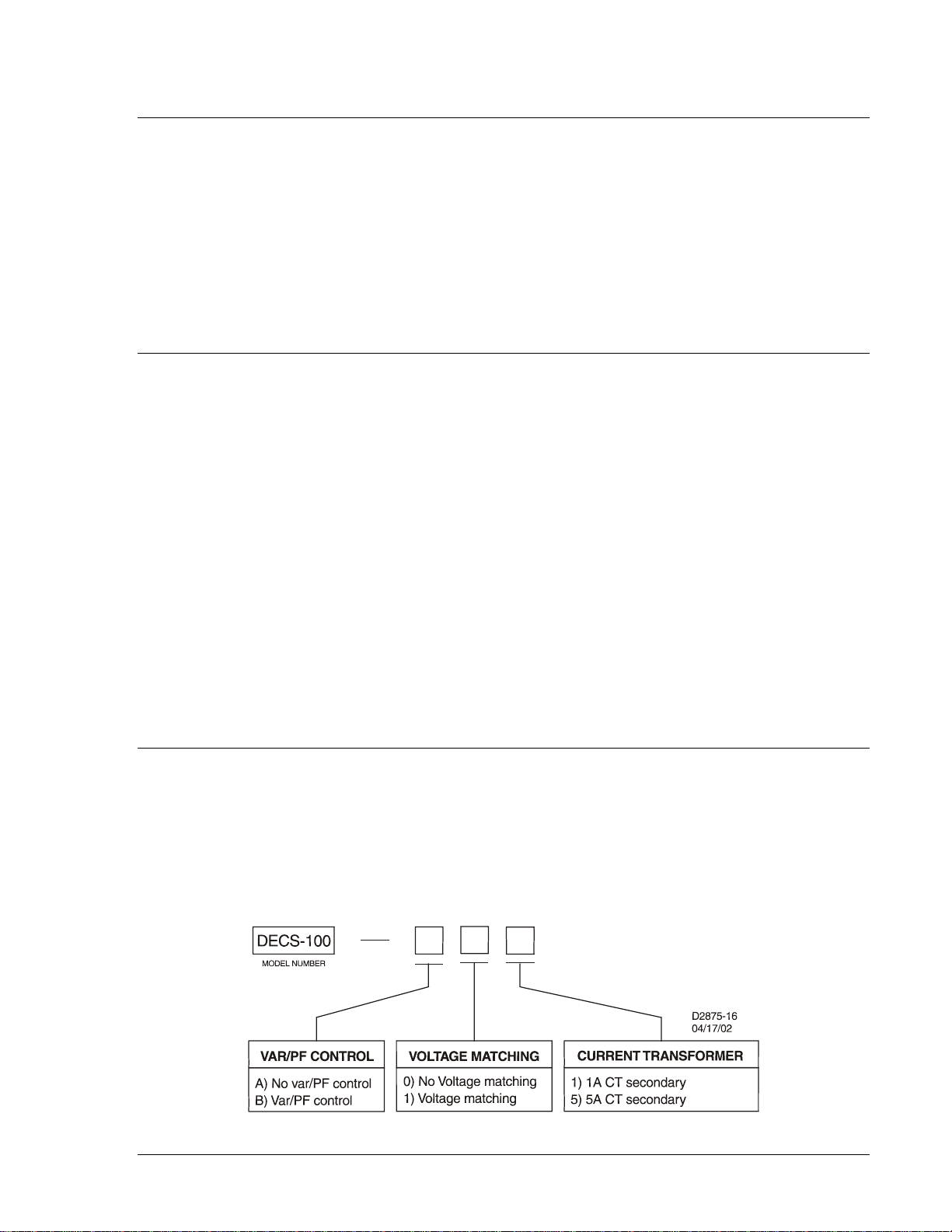
Figure 1-1. DECS-100 Style Chart ................................
Figure 1-2. Typical V/Hz Curves ................................................................................................................ 1-4
9287500991 Rev M DECS-100 General Information i
............................................................................ 1-1
Page 12

This page intentionally left blank .
ii DECS-100 General Information 9287500991 Rev M
Page 13
SECTION 1 • GENERAL INFOR MATION
INTRODUCTION
The Basler Digital Excitation Control System (DECS-100) is an electronic, solid-state, microprocessor
based control device. The DECS-100 regulates the output voltage of a brushless, ac generator by
controlling the current int o the generator ex citer field. Input power to the DECS-100 can be from a mul tipole, high-frequency , permanent magnet ge nerator (PMG) or from t he generator outp ut when used as a
conventional, shunt-excited, excitation system.
The DECS-100 is supplied in an epoxy-potted package designed for behind-the-panel mounting. The
DECS-100 is held in place by thread-forming screws that thread into its plastic shell. Front panel
indicators (LEDs) annunc iate DEC S-100 status and system c onditions. D ECS-100 c onnections ar e made
through quarter-inch, q uick-connect terminals on the r ear panel. A 9-p in DB-9 type conn ector on the rear
panel provides communication between the DECS-100 and an IBM compatible PC.
FEATURES
DECS-100 units have the following features and capabilities:
• Four control modes: automatic voltage regulation (AVR), manual or field current regulation (FCR),
power factor (PF) regulation, and reactive power (var) regulation.
• Programmable stability settings.
• Soft start and voltage buildup control with an adjustable ramp in AVR control mode.
• Overexcitation limiting (OEL) and underexcitation limiting (UEL) in AVR, Var, and PF control modes.
• Underfrequency (volts/hertz) regulation.
• Three-phase or single-phase generator voltage (rms) sensing/regulation in AVR mode.
• Single-phase bus voltage (rms) sensing.
• Single-phase generator current sensing for metering and regulation purposes.
• Field current and field voltage sensing.
• One analog input for proportional remote control of the setpoint.
• Five contact sensing inputs for system interface.
• One common output relay for alarm indication and trip functions.
• Three protection functions: field overvoltage, generator overvoltage, and loss of sensing.
• Generator paralleling with reactive droop compensation and reactive differential compensation.
• Rear RS-232 communication port for personal computer communication using BESTCOMS™
Windows® based software for fast, user-friendly, setup and control.
MODEL AND STYLE NUMBERS
The model number, together w ith the style number, describes the options included in a specific device,
and appear on a label affixed to the r ear panel. Upon receipt of a DEC S-100, be sur e to check the style
number against the requisition and the packing list to ensure that they agree.
Style Number
DECS-100 electrical c haracteristics and oper ational features are defi ned by a combination of let ters and
numbers that make up the style number. The DECS-100 style number chart is shown in Figure 1-1.
Figure 1-1. DECS-100 Style Chart
9287500991 Rev M DECS-100 General Information 1-1
Page 14

Style Number Example
For example, a DECS-100 with a style number of A15 would have the following characteristics and
operating features.
A ------- No var or power factor control
1 -------- Voltage matching
5 -------- 5 ampere current sensing
SPECIFICATIONS
DECS-100 specifications and qualifications are listed in the following paragraphs.
Operating Power
Refer to Section 4, Installation for special requirements concerning the application of operating power
during DECS-100 programming and the application of station power.
Voltage: 88 to 250 Vac, single-phase or three-phase (L-L)
Frequency: 50 to 400 Hz
Power Dissipation: 40 W (maximum continuous)
Burden: 650 VA
Voltage Buildup: ≥6 Vac
Terminals: 3, 4, 5
Generator Voltage Sensing
Type: 1-Phase/3-Phase, 4 ranges
Burden: <1 VA per phase
Terminals: E1, E2, E3
50 Hertz Sensing
Range 1: 100 Vac (85 to 132 Vac)
Range 2: 200 Vac (190 to 220 Vac)
Range 3: 400 Vac (380 to 440 Vac)
Range 4: N/A
60 Hertz Sensing
Range 1: 120 Vac (85 to 132 Vac)
Range 2: 240 Vac (170 to 264 Vac)
Range 3: 480 Vac (340 to 528 Vac)
Range 4: 600 Vac (540 to 660 Vac)
Generator Current Sensing
Type: 1-phase (B-phase), 50/60 Hz
Style XX1: 1 Aac maximum continuous
Style XX5: 5 Aac maximum continuous
Burden: <0.1 VA
Terminals: CT1, CT2
Bus Voltage Sensing (Optional)
Type: 1-phase, 4 ranges
Burden: <1 VA per phase
Terminals: B1, B3
50 Hertz Sensing
Range 1: 100 Vac (85 to 132 Vac)
Range 2: 200 Vac (190 to 220 Vac)
Range 3: 400 Vac (380 to 440 Vac)
Range 4: N/A
60 Hertz Sensing
Range 1: 120 Vac (85 to 132 Vac)
Range 2: 240 Vac (170 to 264 Vac)
Range 3: 480 Vac (340 to 528 Vac)
Range 4: 600 Vac (540 to 660 Vac)
1-2 DECS-100 General Information 9287500991 Rev M
Page 15

Accessory Input
Voltage Range: –3 Vdc to +3 Vdc
Setpoint Range: –30% to +30% shift
Burden: 1 kΩ
Terminals: A, B
Communication Port
Interface: Full duplex RS-232
Connection: Rear panel DB-9 connector
Baud: 4800
Data Bits: 8
Parity: None
Stop Bit: 1
Contact Input Circuits
Type: Dry contacts
Interrogation Voltage: 13 Vdc (supplied by DECS-100)
Terminal Assignments for Standard Functions
Raise: 6U, 7
Lower: 6D, 7
Var/PF Enable: 52J, 52K
Parallel Control: 52L, 52M
Voltage Matching: VM, VMC
Common Alarm Output
Type: Form A
Rated Load: 7 Aac/Adc continuous
Make: 30 Aac/Adc, carry for 0.2 sec
Break: 7 Aac/0.1 Adc
Operating Voltage: 240 Vac/250 Vdc maximum
Terminals: AL1, AL2
Field Output
Continuous Rating: 63 Vdc, 7 Adc
Field Resistance: 9 Ω minimum
Terminals: F+, F–
10 Second Forcing Rating
200 Vac Power Input: 135 Vdc, 15 Adc
110 Vac Power Input: 90 Vdc, 10 Adc (9Ω field)
75 Vdc, 15 Adc (5Ω field)
AVR Operating Mode
Adjustment Range: See Generator Voltage Sensing
Voltage Regulation: ±0.25% over load range at rated power factor and constant generator
frequency.
±0.5% with 3-phase sensing and shunt power at 40% THD of the voltage
waveform (due to a six SCR load).
Temperature Drift: ±0.5% for a 40°C change
V/Hz Characteri stic: Slope from 0 to 3PU is adjustable in 0.01PU increments. Transition
(Corner) frequency is adjustable from 40 to 65 Hz. See Figure 1-2 for the
V/Hz curves.
Response Time: Within 1 cycle
9287500991 Rev M DECS-100 General Information 1-3
Page 16
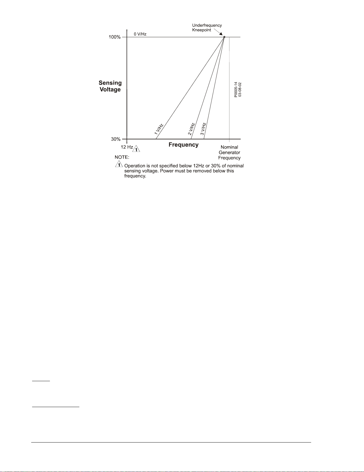
Figure 1-2. Typical V/Hz Curves
FCR (Manual) Operating Mode
Adjustment Range: 0 to 7 Adc
Increment: 0.01 Adc
Var Operating Mode (Optional)
Adjustment Range: –100 to 100%
Increment: 0.1%
PF Operating Mode (Optional)
Adjustment Range: 0.6 lag to 0.6 lead
Increment: 0.001
Parallel Compensation
Modes: Reactive Droop and Reactive Differential (cross-current)∗
Droop Adjust Range: 0 to 10%
Increment: 1%
∗ Burden can exceed 1 VA if external resistors are added to the CT circuit.
Field Overvoltage Protection
Pickup Range: 0 to 250 Vdc
Time Delay: 10 s (fixed)
Generator Overvoltage Protection
Pickup
Range: 100 to 120% of system voltage setting
Increment: 1.0%
Alarm Time Delay
Range: 0 to 10 s
Increment: 1 s
1-4 DECS-100 General Information 9287500991 Rev M
Page 17

Overexcitation Limiter
Pickup
Range: 0 to 15 Adc
Increment: 0.001 Adc
Alarm Time Delay
Range: 0 to 10 s
Increment: 1 s
Underexcitation Limiter
Pickup
Range: 0 to 100% of rated vars
Increment: 1%
Alarm Time Delay
Range: 0 to 10 s
Increment: 1 s
Soft Start Function (AVR Mode Only)
Time Adjust Range: 1 to 7,200 s
Increment: 1 s
Voltage Matching
Accuracy: Generator rms voltage is matched with the bus rms voltage to within
±0.5% of the generator voltage.
Time Adjustment
Range: 1 to 300 s
Increment: 0.01 s
Metering (BESTCOMS™)
Generator Voltage
Range: 10 V to 79 kV
Accuracy: ±0.5% (at 25°C)
Generator Current
Range: 0.04 to 3,000 Aac for 1 A CT (Not to exceed nominal CT rating)
0.2 to 15,000 Aac for5 A CT (Not to exceed nominal CT rating)
Accuracy: ±0.5% (at 25°C)
Frequency
Range: 40 to 65 Hz
Accuracy: ±0.2 Hz (at 25°C)
Field Voltage
Range: 0 to 200 Vdc
Accuracy: ±5.0% (at 25°C)
Field Current
Range: 0 to 20 A
Accuracy: ±0.5% (at 25°C)
Bus Voltage
Range: 10 V to 79 kV
Accuracy: ±0.5% (at 25°C)
Auxiliary DC Input
Range: –3 V to +3 V
Accuracy: ±0.5% (at 25°C)
9287500991 Rev M DECS-100 General Information 1-5
Page 18

Power (Apparent, Real, and Reactive)
Range: 0 to 99 MVA, MW, Mvar
Accuracy: ±3.0% (at 25°C)
Power Factor
Range: –1.0 to –0.6, +0.6 to +1.0
Accuracy: ±0.02 at rated current (25°C), CT input ≥10% nominal rating
Phase Angle
Range: 0 to 360 degrees
Accuracy: ±2.0 degrees (at 25°C), CT input ≥10% nominal rating
Environment
Operating Temperature
DECS-100: –40 to 70°C (–40 to 158°F)
Storage Temperature
DECS-100: –40 to 85°C (–40 to 185°F)
CD-ROM: 0 to 50°C (32 to 122°F)
Type Tests
Shock: Withstands 20 G in three perpendicular planes
Vibration: Withstands 1.2 G at 5 to 26 Hz
Withstands 0.914 mm (0.036 in) double amplitude at 27 to 52 Hz
Withstands 5 G at 53 to 500 Hz
Salt Fog: Qualified per MIL-STD-810E
Physical
Weight
Unit: 1.10 kg (2.42 lb)
Shipping: 1.31 kg (2.88 lb)
Shipping Carton Dimensions (W x H x D)
Single Unit: 299 x 79 x 146 mm (11.75 x 3.125 x 5.75 in)
48 Units: 841 x 653 x 352 mm (33.13 x 25.69 x 13.88 in)
Maritime Recognition
Recognized per standard IACS UR (sections E10 and E22) by the following:
• Bureau Veritas (BV) – BV Rules Pt. C, Ch. 3
• Det Norske Veritas (DNV) – No. 2.4
• Germanischer Lloyd (GL) – VI-7-2
IEC 60092-504 is the base standard for IACS UR sec tion E10. I ACS UR is the ba se standar d for the B V,
DNV, and GL rules listed above.
Additional conditions must be met in order to comply with maritime agency standards, see Section 4,
Installation for further instructions.
EAC Mark (Eurasian Conformity)
• TP TC 004/2011
• TP TC 020/2011
UL Recognized Component
The DECS-100 is recognized to applicable Canadian and US safety standards and requirements by UL.
Standards used for evaluation: UL6200
CE Compliance
LVD 2006/95/EC
BS EN 50178 – Electronic Equipment for use in Power Installations
EMC 2004/108/IEC
IEC 61000-6-2 – Electromagnetic Compatibility (EMC) Immunity for Industrial Environments
IEC 61000-6-4 – Electromagnetic Compatibility (EMC) Emissions Standard for Industrial Environments
1-6 DECS-100 General Information 9287500991 Rev M
Page 19

SECTION 2 • HUMAN-MACHINE INTERFACE
TABLE OF CONTENTS
SECTION 2 • HUMAN-M ACHINE INTERF ACE ....................................................................................... 2-1
INTRODUCTION.................................................................................................................................... 2-1
FRONT PANEL INDICATORS ............................................................................................................... 2-1
Overexcitation Shutdown ................................................................................................................... 2-1
Generator Overvoltage ....................................................................................................................... 2-1
Loss of Generator Sensing ................................................................................................................. 2-1
Overexcitation Limiting ....................................................................................................................... 2-2
Underexcitation Limiting ..................................................................................................................... 2-2
Var/P.F. Mode Active ......................................................................................................................... 2-2
Manual Mode Active ........................................................................................................................... 2-2
Underfrequency Active ....................................................................................................................... 2-2
COMMUNICATION PORT ..................................................................................................................... 2-2
Figures
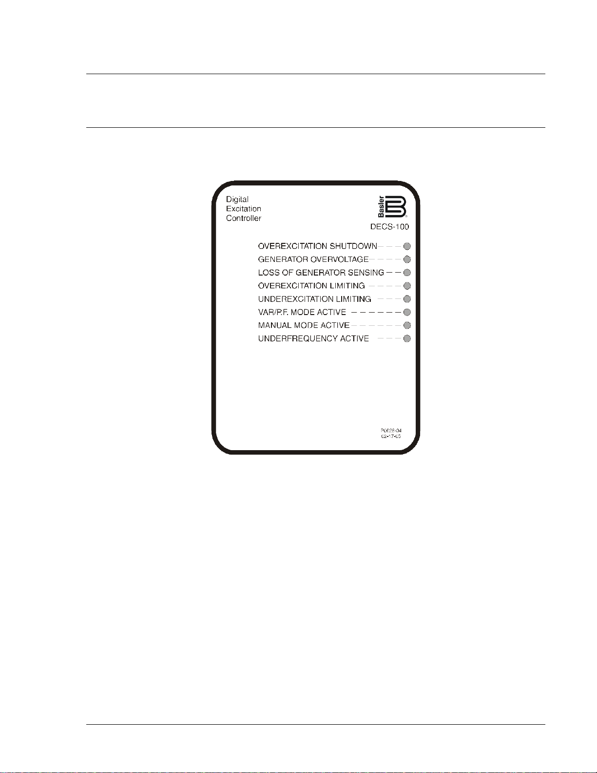
Figure 2-1. DECS-100 Front Panel Indicators ........................................................................................... 2-1
Figure 2-2. DECS-100 Communication Port Location ............................................................................... 2-2
9287500991 Rev M DECS-100 Human-Machine Interface i
Page 20

This page intentionally left blank .
ii DECS-100 Human-Machine Interface 9287500991 Rev M
Page 21
SECTION 2 • HUMAN-MACHINE INTERFACE
INTRODUCTION
The DECS-100 human-machine interface (HMI) consists of front panel indicators and a rear-panel
communication port.
FRONT PANEL INDICATORS
DECS-100 front pane l indicators consist of eight r ed LEDs. The indicators are s hown in Figure 2-1 and
described in the following paragrap hs .
Figure 2-1. DECS-100 Front Panel Indicators
Overexcitation Shutdown
This LED lights when the Over excitation Protection feature is en abled and the field voltage exceeds the
adjustable setpoint for 10 seconds. The DECS-100 will shutdown when an overexcitation condition is
detected. The Overex citation Shutdown L ED will light for 5 seconds when the D ECS-100 is powere d up
following an overexcitation shutdown.
Generator Overvoltage
This LED lights when gen er ator out put vo ltage exc eeds the adjusta ble se tpoint f or 0.75 secon ds. Wh en a
generator overvoltage condition exists, the DECS-100 output contacts close and the DECS-100 shuts
down (if hardware shut down is enabled). The G enerator Overvoltage LED wil l light for 5 seconds when
the DECS-100 is powered up following a generator overvoltage shutdown.
Loss of Generator Sensing
This LED lights when a los s of generator sensing voltage is det ected. When a loss of s ensing condition
occurs, the DECS-100 out put contacts close. D epe nd i ng o n the protective actio n s elected , t h e D ECS -100
will either shutdown or transfer to Manual mode. The Loss of Generator Sensing LED will flash for 5
seconds when the DECS-100 is powered up following a loss of generator sensing shutdown.
9287500991 Rev M DECS-100 Human-Machine Interface 2-1
Page 22
Overexcitation Limiting
This LED lights when the field cur rent exceeds the programmed overexcit ation limit. It stays lit until the
overexcitation condit ion ceases or the overexcitation t ime delay expires and the DEC S-100 shuts down.
The Overexcitation Limit ing LED will flash for 5 seconds when the D ECS-100 is power ed up following an
overexcitation limiting shutdown.
Underexcitation Limiting
This LED lights when the sensed, reactive power (leading vars) decreases below the programmed
underexcitation limit. It stays lit until the underexcitation condition ceases or the underexcitation time
delay expires and th e DECS-100 shuts down. The Underexc itation Limiting LED will flash for 5 s econds
when the DECS-100 is powered up following an underexcitation limiting shutdown.
Var/P.F. Mode Active
This LED lights to ind icate that the DECS-100 is op erating in the optiona l Var or Power Factor mo de of
control. Var/Power Fact or c ontrol is ena bl ed thro ugh B ESTC O MS ™ software and when t he 52J / K contact
input is open.
Manual Mode Active
This LED lights when the DECS-100 is operating in Manual mode. Manual mode is enabled through
BESTCOMS software.
Underfrequency Active
This LED lights when the generator frequency decreases below the underfrequency setpoint and the
DECS-100 is regulating on the selected volts per hertz curve.
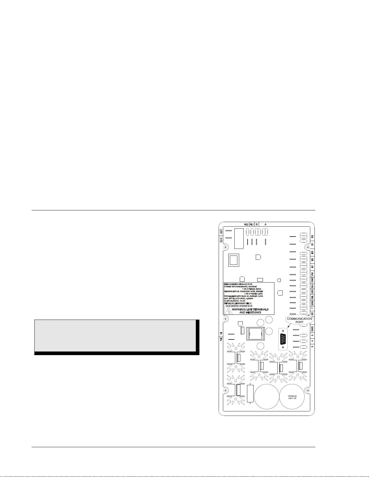
COMMUNICATION PORT
The communication port is located on the rear panel and
consists of a female, RS-232 (DB-9) connector. The
communication port serves as an interface for progra mming
(setup) of the DECS-10 0. Figure 2-2 illustrates the loc ation of
the communication port.
Programming requires a standard, nine-pin, serial
communication cable c onnected between th e DECS-100 and
an IBM-compatible PC operating wit h BESTCOMS software.
BESTCOMS software is a Microsoft Windows®-based
communication software package that is supplied with the
DECS-100. A detai led descriptio n of BESTCO MS is prov ided
in Section 5, BESTCOMS Software.
WARNING!
Lethal voltage is present at the rear panel when the unit is
energized. Rear pa nel connections should be made only
when the unit is de-energized.
Figure 2-2. DECS-100
Communication Port Location
2-2 DECS-100 Human-Machine Interface 9287500991 Rev M
Page 23

SECTION 3 • FUNCTIONAL DESCRIPTION
TABLE OF CONTENTS
SECTION 3 • FUNCTIONAL DESCRIPTION ........................................................................................... 3-1
INTRODUCTION.................................................................................................................................... 3-1
DECS-100 FUNCTION BLOCKS ........................................................................................................... 3-1
Analog Input Circuits .......................................................................................................................... 3-1
Bus Voltage..................................................................................................................................... 3-1
Generator Voltage .......................................................................................................................... 3-1
B-Phase Line Current ..................................................................................................................... 3-2
Accessory Input (Auxiliary Adjust) .................................................................................................. 3-2
Field Voltage ................................................................................................................................... 3-2
Field Current ................................................................................................................................... 3-2
Contact Input Circuits ......................................................................................................................... 3-2
Raise ............................................................................................................................................... 3-2
Lower .............................................................................................................................................. 3-2
Var/Power Factor Control (52J/K) Option ....................................................................................... 3-2
Parallel Generator Compensation (52L/M) ..................................................................................... 3-2
Voltage Matching Control Option .................................................................................................... 3-3
RS-232 Communication Port.............................................................................................................. 3-3
Microprocessor ................................................................................................................................... 3-3
Power Input Stage .............................................................................................................................. 3-3
Power Supply ..................................................................................................................................... 3-3
Power Amplifier Stage ........................................................................................................................ 3-3
Front Panel Indicators ........................................................................................................................ 3-3
Relay Output....................................................................................................................................... 3-3
DECS-100 OPERATING FEATURES ................................................................................................... 3-3
Operating Modes ................................................................................................................................ 3-3
Automatic Voltage Regulation Mode .............................................................................................. 3-3
Manual Mode .................................................................................................................................. 3-4
Var Control Mode (Optional) ........................................................................................................... 3-4
Power Factor Control Mode (Optional) ........................................................................................... 3-4
Reactive Droop Compensation .......................................................................................................... 3-4
Underfrequency .................................................................................................................................. 3-4
Protection ........................................................................................................................................... 3-4
Generator Overvoltage ................................................................................................................... 3-5
Loss of Sensing Voltage ................................................................................................................. 3-5
Field Overvoltage (Overexcitation Shutdown) ................................................................................ 3-5
Limiters ............................................................................................................................................... 3-6
Overexcitation Limiting ................................................................................................................... 3-6
Underexcitation Limiting ................................................................................................................. 3-6
Soft Start ............................................................................................................................................. 3-7
Voltage Matching (Optional) ............................................................................................................... 3-7
Figures
Figure 3-1. Simplified DECS-100 Block Diagram ...................................................................................... 3-1
Figure 3-2. Time Characteristic Curve for Takeover OEL ......................................................................... 3-6
9287500991 Rev M DECS-100 Functional Description i
Page 24

This page intentionally left blank .
ii DECS-100 Functional Description 9287500991 Rev M
Page 25
SECTION 3 • FUNCTIONAL DESC RIPTION
INTRODUCTION
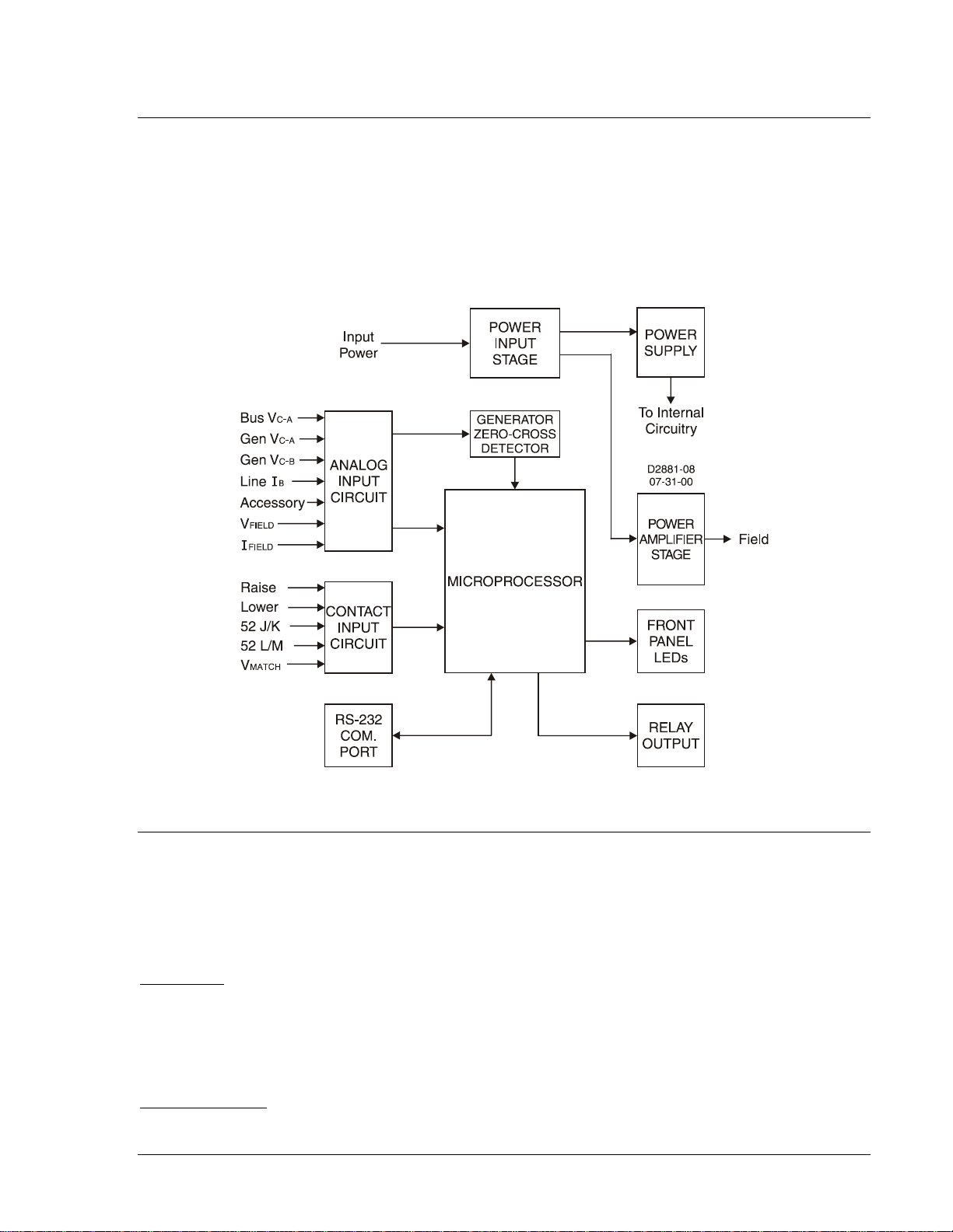
This section describes how the DECS-100 functions and explains its operating features. To ease
understanding, DECS-100 functions are illustrated in the block diagram of Figure 3-1. A detailed
description of each function bl oc k is prov i ded i n t he paragraphs under th e hea din g of DECS-100 Func tio n
Blocks.
DECS-100 operating f eatures include four operating modes, four protect ive functions, st artup provisions,
reactive droop comp ensation, underfrequency c ompensation, and optiona l voltage matching. A detaile d
description of each operating feature is provided in the paragraphs under the heading of DECS-100
Operating Features.
Figure 3-1. Simplified DEC S-100 Block Diagram
DECS-100 FUNCTION BLOCKS
The following paragrap hs describe each of the function block s illustrated in Figure 3-1. The func tion of
each block is explained along with the operation of all function block inputs and outputs.
Analog Input Circuits
Seven analog voltages and current may be sensed and applied to the DECS-100.
Bus Voltage
C-phase and A-phase bus voltages are monitored at terminals B3 an d B1 on units that include voltage
matching. Nominal volta ge s of up to 600 Vac may be s ens ed at thes e t ermi na ls . Vol tag e mon itore d at t h is
input is scaled and conditioned bef ore being applied t o the input of the analog-to-digital converter (ADC) .
This bus voltage signal ap plied to the ADC is used to calcula te the rms value of the bus voltag e across
phases C and A (Bus V
Generator Voltage
Generator voltage is monitored at terminals E1 (A-phase), E2 (B-phase), and E3 (C-phase). Nominal
voltages of up to 600 Vac may be sensed at these terminals. Volt age applied to these inputs is scaled
9287500991 Rev M DECS-100 Functional Description 3-1
C-A
).
Page 26

and conditioned befor e being applied to the input of the A DC. The voltage signal from phas e C and A
(VC-A) of the generator is used by the ADC to calculate the rms value of generator voltage across phases
C and A. Likewise, the voltage signal from p hase C and B (V
) of the generator is used by the ADC t o
C-B
calculate the rms v al ue of g ener at or v olt age ac r oss p h as es C a nd B. T he rms v a l ue o f g enerator phase B
to phase A voltage (V
the phase C to phase B (V
) is calculated by the micr o proc es sor fr om the ph as e C to phas e A si gna l ( V
B-A
) signal.
C-B
Additionally, the generator phas e C to phase A (V
) signal is applied t o a filtered, zero-cross detector
C-A
C-A
)and
circuit. This signal is applied to the microprocessor and is used to calculate generator frequency.
B-Phase Line Current
The phase B line curr ent (IB) signal is d eveloped through a cus tomer supplied current tr ansformer (CT)
and monitored through terminals CT1 and CT2. Depending on the option selected, current up to 1 ampere
(style number xx1) or 5 amperes (style number xx5) rms may be monitored at these terminals. The
current monitored at these terminals is scaled and conditioned by an internal current transformer and
active circuitry for us e by the ADC. The s ignal applied to the A DC is used to calcula te the rms value of
phase B line current.
Additionally, the phas e angle between phase B line current and ph ase C to phase A gener ator voltage is
calculated for use during droop and var/power factor operation.
Accessory Input (Auxiliary Adjust)
This input allows adjustment of the DECS-100 regulation setpoint by the application of a positive or
negative dc voltage across terminals A and B. Positive voltage applied to terminal A with respect to
terminal B will cause th e active mode setpoint to increase. Volt age from –3 to +3 Vdc m ay be applied to
this input. The circ uit induces a 1,000-oh m burden on the dc sour ce. The Application of a ±3 Vdc signa l
corresponds to a ±30 perc e nt chan ge in setpoint.
Field Voltage
Voltage (V
) across the regulator field output terminals, F+ and F–, is monitored, scaled, and
FIELD
conditioned before b eing applied to the ADC. This signal is used to c alculate t he dc valu e of fiel d voltage
for use in system protection.
Field Current
Current (I
) through the main power output switch is converted to a proportional voltage level. This
FIELD
voltage signal is scaled an d conditioned before being applied to the inp ut of the ADC. The resu lt is used
to calculate the dc value of field cur rent for use in the Manual mode of o peration as well as protecti on of
the system.
Contact Input Circuits
Five contact input c ircuits p owered fr om an intern al 13 Vdc po wer supp ly provide input contr ol from us ersupplied, isolated, dry-type contacts.
Raise
Closing a contact across terminals 6U and 7 causes the active operating setpoint to increase. This
function is active as long as the contact is closed.
Lower
Closing a contact across terminals 6D and 7 causes the active operating setpoint to decrease. This
function is active as long as the contact is closed.
Var/Power Factor Control (52J/K) Option
Closing a contact across terminals 52J and 52K disables var/power factor control. An open contact
enables the DECS-100 to c ontrol the g enerat or reac tive pow er in ei ther th e var or t he power fac tor mo de.
The contact has no effect when this function is not enabled in th e software. For more information, see
Parallel Generator Compensation (52L/M) and Voltage Matching Control Option.
Parallel Generator Compensation (52L/M)
Closing a contact across terminals 52L and 52M disables parallel operation. An open contact enables
parallel operation and the DECS-100 operates in reactive droop compensation mode.
3-2 DECS-100 Functional Description 9287500991 Rev M
Page 27

If the Var/Power Factor Control option is present and is enabled in the software, the 52J/K input has
priority. Therefore, if the 5 2J/K and the 52L/M inputs are both open, the system operat es in var/power
factor mode. For more information, see Voltage Matching Control Option.
Voltage Matching Control Option
If the Voltage Matching option is enabled in the s oft w ar e, c los ing a c o ntac t ac ros s ter minals VM a nd VMC
causes the DECS-100 to operate in the voltage matching mode. An open contact disables voltage
matching. Voltage matching is also disabled when either the 52J/K or 52L/M inputs are open.
RS-232 Communication Port
The communication port provides the interface for user programming (setup) of the DECS-100.
Connection is made to the female RS-232 (DB-9) connector wi th a user-supplied, standard 9-pin cable.
The communication port is optically isolated and is powered from a transformer-isolated supply.
Microprocessor
The microprocessor is the heart of the DECS-10 0 and performs measurement, c omputation, cont rol, and
communication funct ions by the use of its embedded program ming and the nonv olatile settings st ored in
its memory.
Power Input Stage
Input power applied to terminals 3, 4, and 5 is rectified and filtered before being app lied to the power
amplifier and the power supply. Input power may be single-phase or three-phase in the range of 88 to 250
Vac at a frequency of 50 to 400 hertz.
The input power source should be properly fused for the application.
Power Supply
The internal switch-mod e p ower supp ly rec eives p ower from the power input sta ge and s upp lies pow er at
the required dc voltage levels to the internal circuitry of the DECS-100.
Power Amplifier Stage
The power amplifier receives power from the power input stage and supplies a controlled amount of
power to the exciter f ield via terminals F+ and F –. The amount of power sup plied to the exciter field is
based on gating pulses r eceived from the m icroprocessor. The pow er amplifier us es a solid state power
switch to provide the r equired power t o the exciter f ield. Power amplifier output to the field is rated up to
63 Vdc at 7 Adc continuous and 135 Vdc at 15 Adc for 10 seconds.
Front Panel Indicators
Eight front-panel LED indicators light to indicate various protective functions and operating modes.
Section 2, Human-Machine Interface provides more information about the front panel indicators.
Relay Output
A common alarm out put contact is provided through terminals AL 1 and AL2. Thi s normally open, form A
contact annunciates alarm or trip conditions. The relay output is latching.
DECS-100 OPERATING FEATURES
The following paragraphs describe the characteristics of each DECS-100 operating feature.
Operating Modes
The DECS-100 provides up to four modes of operation selectable through BESTCOMS™ software.
Automatic voltage regulation mode and Manual mode are standard features. Var and Power Factor
modes are an option.
Automatic Voltage Regulation Mode
In Automatic Voltage Regulation (AVR) mode, the DECS-100 regulates rms generator output voltage.
This is accomplish ed by sensing generator output v oltage and adjusting dc output excitation current to
maintain voltage at the reg ulation setpoint. The regulation setpoint is adjusted by the Raise and Lower
9287500991 Rev M DECS-100 Functional Description 3-3
Page 28

contact inputs, the Accessory input, or t hrough BESTCOMS so ftware. The regulation p oint may also be
modified by the Droop function or the Underfrequency function under certain conditions.
Manual Mode
In Manual mode, also known as Field Current Regulation (FCR) mode, the DECS-100 maintains dc
excitation current at a set level. The current-level setpoint is adjustable from 0 to 7 Adc in 0.01 Adc
increments by the Raise and Lower contact inputs, the Accessory input, or through BESTCOMS software.
CAUTION
The Manual mode excitation level must be evaluated prior to enabling this
feature. If the level of excit ation current is inappr opriat e for the gener ator, sev ere
damage to the generator may occur.
Var Control Mode (Optional)
In Var Control mode, the DECS-1 00 ma int ains generator vars (v olt-am per es , r eac tiv e) at a set level wh en
paralleling with an infinite bus. The DEC S-100 calculates gener ator vars by using t he sensed generator
output voltage and current quantities. It then adjusts the dc excitation current to maintain vars at the
setpoint. Var control is ena bled and dis abled throu gh BESTC OMS softw are. Wh en the softw are is tur ned
on, var control is enabled or disa bled through t he Var/Power Factor Control (5 2J/K) contact input circuit.
The var setpoint is adjustable from 1 00 percent absorb to 100 percent generat e through the Raise and
Lower contact inputs, the Accessory input, or through BESTCOMS software.
Power Factor Control Mode (Optional)
In Power Factor Control mode, the DECS-100 maintains generator power factor at a set level when
paralleling with an infinite bus. The DECS-100 calculates generator power factor using the sensed
generator output voltage and current quantities and then adjusts the dc excitation current to maintain
power factor at the setpoint. Power factor c ontrol is enabled or disabled through BESTCO MS software.
When the software is turn ed on, it is enabled or disab led through the Var/Power Factor Control (52J/K)
contact input circuit. The power factor setpoint is adjus table between 0.6 lag and 0.6 lead throu gh the
Raise and Lower contact inputs, the Accessory input, or through BESTCOMS software.
Reactive Droop Compensation
The DECS-100 provides a r eactive droop compensation feature to as sist in the sharing of reactive load
during parallel generat or operation. When th is feature is enabled, the DECS-100 calculates the reactive
portion of the generator load using the sensed gener ator output voltage and current quantities and then
modifies the voltage re gulation setpoint accordingly . A uni ty power factor gener ator load resu lts in almost
no change in generator output voltage. A lagging power factor generator load (inductive) results in a
reduction of generator output voltage. A leading power factor generator load (capacitive) results in an
increase of generator outp ut voltage. Droop is adjustable up to 10 percent with rated, nominal B-phase
line current (1 amp ere or 5 amperes applied throug h terminals CT1 a nd CT2) and 0. 8 power factor. The
droop feature is enable d and disabled thr ough the Paralle l Generator Com pensation contact input circuit
(terminals 52L and 52M). Droop is also disabled when operating in var or power factor control modes.
Underfrequency
When generator frequency drops below the selected knee frequency setpoint, the voltage setpoint is
automatically adjusted by t he DECS-100 so that gene rator v oltag e fo llow s t he sel ec ted PU ( p er uni t) V/Hz
curve. When operating on the s elected PU V/Hz curve, the Underf requency Active ind icator lights on the
front panel and in BESTCOMS. Under freq uenc y control is disabled below 12 hertz. The knee frequency is
adjustable from 40 to 65 hertz in 0.1 hertz increments and the PU V/Hz curv e may be set at a s lope of 0
to 3 in 0.01 steps through BESTCOMS software. A slope of 0 eff ectively disables the underfrequency
function. The DECS-100 has a minimum regulation point of approximately 30 percent of the nominal
setpoint.
Protection
The DECS-100 includes three protective functions: gener ator overvoltage, loss of sensi ng voltage, and
field overvoltage. Eac h protective function h as a corresponding fr ont panel indicat or that lights when the
function is active. An active protective function is also annunciated through BESTCOMS.
3-4 DECS-100 Functional Description 9287500991 Rev M
Page 29

Generator Overvoltage
A generator overvoltage condition can be configured (in BESTCOMS) to close the DECS-100 relay
output, disable the D ECS-100, init iate both actio ns, or initiat e neither act ion. When the se nsed generator
voltage increases above th e adjustab le vo ltage lev el s etpoint f or the dur ation of the ad justa ble alar m time
delay, the DECS-100 initiates the selected action.
If the DECS-100 is configured to c lose the relay output, a generator overvol tage condition will light the
front panel and BESTC OMS Gen erator Over voltage in dicator and c lose the r elay output at ter minals A L1
and AL2.
If the DECS-100 is config ured for hardware shutd own, a generator overvolt age condition will disab le the
DECS-100 after the alarm time delay expires. When t he DECS-100 is powered up fol lowing a generator
overvoltage shutdown, the Generator Overvoltage indicator will light for five seconds.
The voltage level setpoint i s adjustable from 10 0 to 120 % of the system v oltage setting. The alarm t ime
delay is adjustable from 0 to 10 seconds.
Loss of Sensing Voltage
The DECS-100 monitors the sensed generator output voltage and takes protective action if a loss of
sensing voltage is detected. A loss of sensing voltage is detected during the following conditions.
• The sensed voltage is less than 50 percent of the rated voltage (one-phase or three-phase sensing).
• A total loss of any phase occurs (three-phase sensing).
• The voltage difference between any phase (line-to-line) and the three-phase average exceeds 20
percent of nominal (three-phase sensing).
A time delay of 0 to 25 se conds is adjustable through B ESTCOMS software. This delays the protectiv e
action in order to allow field forcing in applications that do not sense B-phase generator current. The
default time delay setting is 10 seconds.
BESTCOMS software al lows the selection of one o f two protective ac tions for a loss of sens ing. Either a
complete shutdown or a transfer to Manual mode may be selected.
If shutdown is selec t ed and a los s of sensing occurs , t he Loss of Generator Sens i ng ind ic ator on t he fro nt
panel and in BESTCOMS lights, the relay output closes, and the DECS-100 shuts down after the
adjustable time delay ex pires. When the DECS-100 is powered up follow ing a loss of genera tor sensing
shutdown, the Loss of Generator Sensing indicator will light for five seconds. However, if the loss of
sensing conditions st ill exists, the DECS-100 will n ot shut down due to loss of sensing until the soft -start
time delay and the loss of sensing time delay expires.
If transfer to Manu al is s ele cted a nd a loss of sens ing occ urs, the r elay out put clo ses , and th e DEC S-100
transfers to the Manual mode of operation after the adjustable time delay expires. The DECS-100 will
remain in this mode of oper ation until switched via BE STCOMS. Prior to selectin g transfer to Manual on
loss of sensing, it is necessary to determine an appropriate Manual (FCR) mode setpoint level to be
transferred to. An inappropriate excitation level could result in severe damage to equipment.
This function is disabled when the fr equency decreas es below 12 hertz or when a generat or short circuit
condition is detected. A generator short-circuit is determined wh en the B-phase CT current ex ceeds thr ee
times the per unit value. Loss of sensing shutdown or transfer is not active during the soft-start time.
Field Overvoltage (Overexcitation Shutdown)
A field overvoltage condition can be configured (in BESTCOMS) to close the DECS-100 relay output,
disable the DECS-1 00, initiate both actions, or initiat e neither action. When the field voltage increases
above the adjustable vo ltage level setpoint for the fixed dur ation of 10 seconds, the DECS-100 initiates
the selected action.
If the DECS-100 is configu red to close the relay output, a field overv oltage condition will light the front
panel and BESTCOMS Ov erexcitation Shutdown indicator and close the relay output at terminals AL1
and AL2.
If the DECS-100 is configured for hardware shutdown, a field overvoltage condition will disable the DECS100 after the 10 second time delay expires. When the DECS-100 is powered up following a field
overvoltage shutdown, the Overexcitation Shutdown indicator will light for five seconds.
The voltage level setp oint is adjustabl e from 0 to 250 Vdc . The field ov ervoltage time de lay is fixed a t 10
seconds.
9287500991 Rev M DECS-100 Functional Description 3-5
Page 30

Limiters
3level var rated ××=
BAVG
IV
DECS-100 limiters c onsist of an overexcit ation limiter (OEL) triggered by an increas e in field current and
an underexcitation limiter (UEL) triggered by excessive leading vars.
Overexcitation Limiting
The DECS-100 provides two types of overexcitation limiting: summing point and takeover.
Summing Point OEL. When the level of field cur rent increases above the ad justab l e c urr ent lev e l setpo int,
the front panel and BESTCOMS Overexcitation Limiting indicators light. If the overexcitation condition
persists for the dur ation of the user-adjustable alar m time delay, the relay output at terminals AL1 and
AL2 closes.
The advantage of a summi ng-point type of OEL is tha t it can provide a smooth trans ition into and out of
the limit. Its drawbac k is that it does not c ontrol field cur rent directly, but has to work throug h the normal
voltage regulator, and may be influenced by changes in terminal voltage.
Takeover OEL. When takeover-style overexcitation limiting is used, the level of field current at which
limiting occurs is de termined by an adjustab le current level set point. If the field cur rent increases above
the adjustable curr ent level setpoint, the front p anel and BESTCOMS Overex citation Limiting indicators
light and the field current is limited and forced to follow the characteristic time curve. See Figure 3-2.
The advantage of a takeover type of OEL is that it provides direct control of the exciter field current
without relying on the normal voltage regu lator’s control act ion. Its drawback is that it may not provide a
smooth transition into and out of the limit.
If hardware shutdown is enabled, the D ECS-100 will be disab led when the time delay expires. W hen the
DECS-100 is powered up following a shutdown triggered by overexcitation limiting, the Overexcitation
Limiting indicator will light for five seconds.
The current level s etpoint i s adjustab le from 0 to 15 Adc. The alarm tim e delay is adjus table from 0 to 10
seconds.
Figure 3-2. Time Characteristic Curve for Takeover OEL
Underexcitation Limiting
When the level of leading vars increases above the adjustable var level setpoint, the front panel and
BESTCOMS Underexcitation Limiting indicators light. If the underexcitation condition persists for the
duration of the adjustable alarm time delay, the relay output at terminals AL1 and AL2 closes.
If hardware shutdown is enabled, t he DECS-100 will be disab led when the time delay expires . When the
DECS-100 is powered up foll owing a shutdown triggered by underexcitation limiting, th e Underexcitation
Limiting indicator will light for five seconds.
The var level setpoint is adj ustable fr om 0 to 100% of the rate d var s. The r ated va r level is det ermined by
the following equation:
Where IB is the DECS-100 nominal current sensing rating (1 Aac or 5 Aac)
3-6 DECS-100 Functional Description 9287500991 Rev M
Page 31

The alarm time delay is adjustable from 0 to 10 seconds.
NOTE
The UEL function is active only during parallel operation when the 52J/K
contact input or 52L/M contact input is open.
Soft Start
The DECS-100 also incorporates an adjustable soft start feature that controls the time for generator
voltage or field current to r amp to the regulation setpoint. The ra mp rate is adjustable from 1 to 7,200
seconds in 1 second increments through BESTCOMS. The under frequency feature is also active dur ing
soft start and takes priority in control of the generator voltage in an effort to minimize voltage overshoot.
Voltage Matching (Optional)
Voltage matching is useful when the PT ratios in an application are not matched exactly. Using
BESTCOMS to enter the gener ator PT ratio and bus PT ratio will automat ical ly compe nsate for t he offset .
The DECS-100 voltage matc hing optio n automat ically matches the r ms gen erator output with the r ms bus
voltage prior to synchr onizing. The D ECS-100 co mpares and ma tches the g enera tor voltage wit h the bus
voltage by adjusting th e dc excitat ion current. Voltage match ing is enabled when the bus voltage input is
within 10% of the n ominal generator secondary input sensing range selected . As long as the values o f
generator and bus voltage (applies secondary voltage to the D ECS-1 00 v ol tag e s ensing inp uts ) ar e with in
the acceptable range, voltage matching can be achieved.
The rate at which the DECS-100 matches the generator input level with the bus input level is controlled by
a voltage matching speed setting. this setting is adjustable from 1 to 300 seconds in 0.01 second
increments.
Voltage matching can be disabled by the state of the DECS-100 contact inputs. In BESTCOMS, the
52J/K contact input, 52L/ M contact input, or bo th contact inputs can be c onfigured to enabl e and disable
voltage matching. To enab le bus voltage matching, select 5 2J/K. This will allow droop to re main active.
When the utility tie break er closes, voltag e matching wil l be disabled aut omatically (via th e 52J/K contact
input) and var/power factor control will be enabled.
Two voltage matching modes are available: Maintain and Revert. When Maintai n mode is implemented,
the DECS-100 setpoint is maint a ined at t he b us volta ge l ev el eve n w h en th e ge n er ator or ut il ity br eak er is
open. When Revert mode is implemented, the DECS-100 setpoint rever ts to its original level when the
generator or utility breaker opens. Revert is the default voltage matching mode.
9287500991 Rev M DECS-100 Functional Description 3-7
Page 32

This page intentionally left blank .
3-8 DECS-100 Functional Description 9287500991 Rev M
Page 33

SECTION 4 • INSTALLATION
TABLE OF CONTENTS
SECTION 4 INSTALLATION ..................................................................................................................... 4-1
INTRODUCTION.................................................................................................................................... 4-1
MOUNTING ............................................................................................................................................ 4-1
CONNECTIONS..................................................................................................................................... 4-4
DECS-100 Terminations .................................................................................................................... 4-4
Bus Voltage Sensing Inputs (Optional) .............................................................................................. 4-5
Generator Voltage Sensing Inputs ..................................................................................................... 4-5
Phase B Line Current Sensing Input .................................................................................................. 4-5
Accessory Input .................................................................................................................................. 4-5
Raise and Lower Contact Inputs ........................................................................................................ 4-5
Var/Power Factor Control Contact Input (Optional) ........................................................................... 4-5
Parallel Generator Com pen s ation ...................................................................................................... 4-6
Parallel Control and Var/PF Control Inputs ........................................................................................ 4-6
Voltage Matching (Optional) ............................................................................................................... 4-6
Power Supply Inputs .......................................................................................................................... 4-6
Chassis Ground .................................................................................................................................. 4-6
Power (Field) Output .......................................................................................................................... 4-6
Relay Output (Alarm) .......................................................................................................................... 4-7
Communication Port ........................................................................................................................... 4-7
DECS-100 Connections for Typical Applications ............................................................................... 4-7
INSTALLATION FOR CE COMPLIANCE ............................................................................................ 4-13
Mounting ........................................................................................................................................... 4-13
Wiring ............................................................................................................................................... 4-13
Installation for EMC Compliance.......................................................................................................... 4-14
Protection ......................................................................................................................................... 4-14
Mounting ........................................................................................................................................... 4-14
Wiring ............................................................................................................................................... 4-14
Ferrite Beads .................................................................................................................................... 4-14
PRELIMINARY SET U P ........................................................................................................................ 4-15
Operating Power Considerations During DECS-100 Programming................................................. 4-15
ADJUSTMENTS................................................................................................................................... 4-16
Figures
Figure 4-1. DECS-100 Dimensions ........................................................................................................... 4-2
Figure 4-2. Cutout and Drilling Dimensions ............................................................................................... 4-3
Figure 4-3. DECS-100 Terminals .............................................................................................................. 4-4
Figure 4-4. RS-232 Port Pin Assignments ................................................................................................ 4-7
Figure 4-5. Personal Computer to DECS-100 Connections ...................................................................... 4-7
Figure 4-6. Typical Connections for PMG Application with ABC Rotation and Three-Phase Sensing ..... 4-8
Figure 4-7. Typical Connections for PMG Application with ABC Rotation and Single-Phase Se ns ing .... 4-9
Figure 4-8. Typical Connections for Shunt Application with ABC Rotation and Three-Phase Sensing .. 4-10
Figure 4-9. Typical Connections for Shunt Application with ABC Rotation and Single-Phase Sensing . 4-11
Figure 4-10. Typical Connections for Station Power Application and Three-Phase Sensing ................. 4-12
Figure 4-11. Cross-Current (Reactive Differential) Connections ............................................................. 4-13
Figure 4-12. Operating Power Connections for DECS-100 Programming (Inpu t Voltage >1 20 Vac ) ..... 4-16
Tables
Table 4-1. Bus Voltage Sensing Terminals ............................................................................................... 4-5
Table 4-2. Generator Voltage Sensing Terminals ..................................................................................... 4-5
Table 4-3. 52L/M and 52J/K Control Modes .............................................................................................. 4-6
Table 4-4. Communicat ion Por t Pin Functions .......................................................................................... 4-7
Table 4-5. Ferrite Bead Specifications and Corresponding Wire Terminals ........................................... 4-14
9287500991 Rev M DECS-100 Installation i
Page 34

This page intentionally left blank .
ii DECS-100 Inst all ati on 9287500991 Rev M
Page 35

SECTION 4 • INSTALLATION
INTRODUCTION
DECS-100 Digital Exc itat io n Con tr ol Sys tems are d el iv ered in s tur dy c ar t ons t o pr ev ent s h ipp ing da mag e.
Upon receipt of a system, c hec k the p ar t nu mber a gainst the requisitio n an d pack a gin g l ist for agr e em ent.
Inspect for damage, and if there is evidenc e of such, immedia tely file a claim wit h the carrier and notify
the Basler Electric Regiona l Sales Office, your Sal es Representative or a Sales Representativ e at Basler
Electric, Highland, Illinois.
If the unit is not install ed im mediate ly, store it i n the ori ginal sh ippin g pack age in a mo isture and dus t fr ee
environment.
MOUNTING
The DECS-100 is normally located in the generator conduit box. It is designed for behind the panel
mounting and requires a c utout for front panel view ing. Supplied mount ing hardware consists of six #12
thread-forming screws that pass through mounting holes in the conduit box and thread int o the plastic
shell of the DEC S-100. The recommen ded torque range for the stee l mounting screws is 4.07 to 4.5 2
newton-meters (36 to 40 in ch-pounds). The unit must be mo unted where the ambient tem perature does
not exceed the allowable environmental conditions called out in Section 1, General Information,
Specifications. DECS-1 00 package dimensions are s hown in Figure 4-1. Cutou t and drilling dimensions
are shown in Figure 4-2. Drawing dimensions are shown in inches and millimeters (in parenthesis).
9287500991 Rev M DECS-100 Installation 4-1
Page 36

Figure 4-1. DECS-100 Dimensions
4-2 DECS-100 Installation 9287500991 Rev M
Page 37

Figure 4-2. Cutout and Drilling Dimensions
9287500991 Rev M DECS-100 Installation 4-3
Page 38

CONNECTIONS
DECS-100 connections are dependent on the application and excitation scheme. Incorrect wiring may
result in damage to the unit. Check the part number to ensure that you have the correct unit before
connecting and applying pow er.
NOTE
Be sure that the DECS-100 is hard-w ired to ear th grou nd with no s maller th an 12
AWG copper wire attache d to the ground terminal on the rear of the unit case.
When the unit is configure d in a system with other devices, connect a separate
lead from the ground bus to each DECS-100 un it.
DECS-100 Terminations
DECS-100 units have two types of interface terminals (Figure 4-3). One type is quarter-inch, quickconnect terminals an d t he other is a 9-pin D B9 c onn e c tor . A ll ter m ina ls ar e l oc at ed o n t he r e ar of the unit.
The quarter-inch, quick-connect terminal labels are located on the rear of the case. Wires performing
common functions, such as voltage sensing leads, should be grouped together. The 9-pin DB-9 type
connector is used for temporary interface with both IBM compatible PCs and hand-held computers.
Figure 4-3 shows the term inal connections loc ated on the rear panel of t he DECS-100. Except as noted
above, connections should be made with minimum wire size of 14 AWG.
Figure 4-3. DECS-100 Terminals
4-4 DECS-100 Installation 9287500991 Rev M
Page 39

Bus Voltage Sensing Inputs (Optional)
Bus Voltage Phase
Terminal
A
B1 C B3
Sensing
Generator
Phase
Terminal
A
E1
B
E2 C E3
A
E1
C
E2, E3
The bus voltage sensing terminals are labeled B1 and B3. Thes e terminals are used only on units th at
include the Voltage Matc hing opt ion. The bus input is not phas e sensit ive to g ener ator sens ing. Tab le 4-1
lists the terminal assignments for bus voltage sensing.
Table 4-1. Bus Voltage Sensing Terminals
Generator Voltage Sensing Inputs
The generator voltage s ens ing termi nals ar e labe led E1, E2 , and E 3. The DECS -100 c omes equipped for
three-phase sensing as s tandard. Single-phase sensing is obtained by connecting the C-phase sensing
input to terminals E2 and E3. Table 4-2 lists the terminal assignments for thr ee-phase and single-phase
generator voltage sensing.
Table 4-2. Generator Voltage Sensing Terminals
3-Phase
1-Phase
Phase B Line Current Sensing Input
Generator line current is stepped down through a user-supplied current transformer (CT). Secondary
current from that transformer is applied to terminals labeled CT1 and CT2.
Accessory Input
The accessory input voltage terminals are labeled A and B and accept a maximum signal of ±3 Vdc.
Positive voltage applied to terminal A with respect to terminal B causes the active mode setpoint to
increase. For every ±1 Vdc change, a ±10% change in the active mode setpoint is achieved.
Raise and Lower Contact Inputs
Remote setpoint adjustment may be accomplished by connecting a single-pole, double-throw (SPDT),
spring return, center-off s witch to the terminals labe led 6U, 7, and 6D. To connect this s witch, the center
pole, or common terminal, must be connected to terminal 7. The other two termin als are connected to
terminals 6U and 6D.
This remote adjust switc h may be mou nted up to 150 feet away from the D ECS-100 when using twist ed,
shielded cable. Only dry, ungrounded switching contacts should be applied to the Raise and Lower
contact inputs.
Var/Power Factor Control Contact Input (Optional)
A customer-supplied enab le/disable contact for this function conn ects to the terminals labeled 52J and
52K.
Only dry, ungrounded switching contacts should be applied to the Var/Power Factor Control contact input.
9287500991 Rev M DECS-100 Installation 4-5
Page 40

Parallel Generator Compensation
DECS-100 Operating Mode
52L/M
52J/K
Generator Operating Mode
AVR mode active, no droop, optional
var/PF mode disabled
Closed
Closed
Single unit/stand-alone
Droop mode active, optional var/PF
Open
Closed
Paralleled to the utility grid (droop) or
(droop or CCC)
Var/PF mode active
Open
Open
Paralleled to utility grid
A customer-supplied enabl e/disable contact for this function connects to the termin als labeled 52L and
52M.
Only dry, ungrounded switching contacts should be applied to the Parallel Generator Compensation
contact input.
Parallel Control and Var/PF Control Inputs
User-supplied contacts at terminals 52L and 52M determine whether AVR or Droop mode is active.
Terminals 52L and 52M typically connect to a 52b auxiliary contact of the generator breaker. Usersupplied contacts at terminals 52J and 52K control whether var or power factor correction is active or
disabled. Terminals 52J and 52K typ ically connec t to the auxili ary contac ts of the utility tie break er. Table
4-3 lists the operating modes achieved for the d ifferent 52L/M and 52J/K co ntact states. A closed stat e
indicates a continuous contact closure and an open state indicates a continuous open-circuit.
Table 4-3. 52L/M and 52J/K Control Modes
mode disabled
Voltage Matching (Optional)
A customer-supplied enable/disable contact for this function connects to the terminals labeled VM and
VMC. Only dry, ungrounded switching contacts should be applied to the Voltage Matching contact input.
Voltage matching is also enabled/disabled by the state of the 52J/K and/or 52L/M contact inputs. In
BESTCOMS™, voltage matching can be configured to be disabled when the 52J/K or 52L/M contact input
is open or just the 52J/K contact input is open.
Power Supply Inputs
Power input terminals are labeled 3, 4, and 5. Single-phase or three-phase power may be applied. Singlephase power may be applied to any two of the three terminals.
The DECS-100 can be pow ered directly from a vari ety of sources as long as the DECS-100 inpu t power
specifications are followed (see Section 1, General Information, Specifications).
Examples of DECS-100 operating power sources are:
• Generator (shunt fed)
• Permanent magnet generator (PMG)
• Auxiliary winding
When powering the DECS-100 from a lo w-impedance power source, specia l provisions must be mad e to
avoid damage to t he DECS-100. Examples of a low-impedanc e power source include a stat ion service
source or power out let. An Inrush Current R eduction Module, ICRM-7, must be connected b etween the
power source and DECS-1 00 input power terminals ( see Figure 4-10). The ICR M-7 prevents DECS-100
damage by minimiz ing the level of inrush current. T he ICRM-7 can also be used when programm ing the
DECS-100. However, the Preliminary Setup paragraphs illustrate an alternate method for temporarily
powering the DECS-100 for programming.
More details about the ICRM-7 are available in Basler Electric publication 9387900990 .
two or more generators islanded
Chassis Ground
The chassis ground terminal is labeled GND.
Power (Field) Output
The field output terminals for connection to the generator exciter field are labeled F+ and F–.
4-6 DECS-100 Installation 9287500991 Rev M
Page 41

Relay Output (Alarm)
Pin
Function
Name
Direction
1
N/C
—
N/A 2 Transmit data
TXD
From DECS-100
3
Receive data
RXD
To DECS-100
4
N/C
—
N/A 5 Signal ground
GND
N/A 6 N/C
—
N/A
7
N/C
—
N/A
8
N/C
—
N/A 9 N/C
—
N/A
The common alarm relay output contact may be accessed at the terminals labeled AL1 AND AL2.
Communication Port
The RS-232 port on the rear panel us es a DB-9
female connector. Figure 4-4 Illustrates the pin
assignments of the communication port and
Table 4-4 Identifies the RS-232 connector pin
functions. A standard communication cable
terminated with a DB-9 male conn ector is used
for PC interface w ith the D ECS-100 as shown in
Figure 4-5.
Table 4-4. Communicat ion Port Pin Funct ions
Figure 4-4. RS-232 Port Pin Assignments
Figure 4-5. Personal Computer to DECS-100 Connections
DECS-100 Connections for Typical Applications
Figures 4-6 through 4-10 illustrate typical applications using the DECS-100. Figure 4-6 shows an
application where DECS-100 op erating power is der ived from a permanent magn et generator ( PMG) and
three-phase voltage s ensing is app lied to the DECS-1 00. Figure 4-7 shows anot her PMG app lication but
with single-p hase voltage sensing. Figur e 4-8 shows an applic ation where D ECS-100 operati ng power is
derived from the generator output (shunt application) and three-phase voltage sensing is applied to the
DECS-100. Figure 4-9 shows another shu nt a pplication but with single-phase sen s ing. F igure 4-10 shows
a DECS-100 powered by single-phase station power in a three-phase sensing application.
Figure 4-11 shows a typic al connection diagram for tw o paralleled generators o perating in cross-current
compensation (reactive differential) mode. Th e res ist or s s hown hav e a valu e of 0.1 ohms. This is a typical
9287500991 Rev M DECS-100 Installation 4-7
Page 42

value that can be used to set the burden. (Ensure that the resistor power rating is adequate for the
POWER
4 CT
1 CT2
V
OLTAGE
E3
E2 E1 52J 52K 52L 52M
CONTROL CONTROL
52b
S2
5
1
0
21
10
U
til
ity
Side
A
B
C
CBA
52
10
7
10
7
10
10
8
6
G
en
e
ra
to
r
Side
CTB
+
GEN
PMG
D2881-09
0
5-1
0-0
2
10
OUTPU
T
F- F+ 3
6D 7 6U AL 1 AL
2
S1
A B VM VMC
S3
109
5
4
3
10
FIELD
I
NPUT
CTB
SENSING VAR/PF
ADJUST
EXTE
RNAL
PA
RALLEL
DE
CS-100 WITH
VOLTAGE MATC
HING
ALARM
A
UX.
ADJUST
VOLTAGE
M
ATCHING
B1 B3
BUS
GROUND
GND
NOTES:
11
3
4
5
6
7
8
1
2
9
10
11
Requir
ed onl
y for o
ptiona
l Var/P
F contr
ol. Va
r/PF is
activ
e with
52b
open.
Var/PF
is ina
ctive with 52b closed.
Parallel control and droop active with S2 open, inactive with S2
c
los
ed.
S1 (SPDT, spring-return to center-off position) adjusts DECS-100
se
t
po
i
nt
.
Normally-open output contact closes for customer alarm or trip.
Analog input voltage between +/- 3 Vdc provides adjustment of
vol
tage
se
tpo
int.
Ex
t
er
na
l
f
use
s sh
oul
d b
e B
ussm
an
typ
e KT
K-1
0 o
r e
quiv
ale
nt.
Sensing potential transformer is required if line voltage exceeds
6
60
Vac
.
3
-ph
ase
PMG
is
sh
own.
Fo
r 1
-pha
se
PMG
, o
mit
B-p
has
e
co
n
nec
tio
n.
O
p
ti
on
a
l
vo
l
ta
ge
ma
t
ch
in
g
c
on
t
ro
l
in
put
. Vo
lta
ge
mat
chin
g i
s
active with S3 closed, inactive with S3 open.
Ite
m n
ot
sup
plie
d b
y B
asl
er E
lec
tri
c.
Whe
n g
ene
rat
or r
ota
tio
n i
s AC
B,
the
con
nec
tio
ns
show
n f
or
CTB
should be reversed.
installation.)
Figure 4-6. Typical Connections for PMG Application with ABC Rotation and Three-Phase Sensing
4-8 DECS-100 Installation 9287500991 Rev M
Page 43

C
TB
+
A
GEN
B
C
FIEL
D
OUTPUT
F- F+
INPUT
POWER
3 4
A
LARMCTB
CT1
CT2
VOLT
AGE
SEN
SING
E3 E
2 E1
DECS
-100 W
ITH VOL
TAGE M
ATCHING
52J 52K 5
2L 52M 6D
7 6U
VAR/PF
CONTROL CONTROL ADJUST
EXTERNA
L
AL 1 AL
2
PARA
LLEL
52b
S
2
S
1
CB
A
PM
G
D2881-11
05-10-02
5
10
AUX.
A
DJUST
A
B
VOLT
AGE
MATCHIN
G
VM VMC
S
3
10
9
54
3
10
21
10
1
0
7
10
8
6
Ge
ne
r
at
o
r
Side
U
ti
l
it
y
Side
NOT
ES:
10
5
2
10
7
10
B1 B3
BUS
GR
OUND
GND
3
4
5
6
7
8
1
2
9
10
11
Required only for optional Var/PF control. Var/PF is active with
52b
op
en.
Var
/PF
is
ina
cti
ve
with
52
b c
los
ed.
Parallel control and droop active with S2 open, inactive with S2
cl
osed
.
S1 (SPDT, spring-return to center-off position) adjusts DECS-100
s
etp
oin
t.
No
rmal
ly-
ope
n ou
tpu
t c
ont
act
clo
ses
for
cu
sto
mer
ala
rm
or
tri
p.
Analog input voltage between +/
- 3
Vdc
pr
ovid
es
adj
ust
ment
of
vol
tage
se
tpo
int.
External fuses should be Bussman type KTK-10 or equivalent.
Sensing potential trans
for
mer
is
req
uir
ed
if l
ine
vo
lta
ge e
xce
eds
66
0
V
ac
.
3
-
ph
as
e
P
MG
is
sh
ow
n
.
Fo
r
1
-p
h
as
e
P
MG
,
o
mi
t
B
-p
h
as
e
con
nec
tio
n.
O
p
ti
on
a
l
v
ol
ta
g
e
ma
t
ch
in
g
c
on
t
ro
l
i
np
u
t.
V
o
lt
ag
e
m
a
tc
hi
n
g
is
act
ive
wit
h S3 closed, inactive with S3 open.
Item not supplied by Basler Electric.
When generator rotation is ACB, the connections shown for C
T
B
s
h
ou
ld
be
r
e
ve
r
se
d.
9287500991 Rev M DECS-100 Installation 4-9
Figure 4-7. Typical Connections for PMG Application with ABC Rotation and Single-Phas e Se nsing
Page 44

CTB
+
A
GEN
B
C
FIELD
OUTPUT
F- F+
INPUT
POWER
3 4
ALARMCTB
CT1 CT2
VOLTAGE
SENSING
E3 E2 E1
DECS-100 WITH VOLTAGE MATCHING
52J 52K 52L 52M 6D 7 6U
VAR/PF
CONTROL CONTROL ADJUST
EXTERNAL
AL 1 AL 2
PARALLEL
52b
S2
S1
D2881-10
05-10-02
5
10
AUX.
ADJUST
A B
VOLTAGE
MATCHING
VM VMC
S3
109
54
3
10
21
10
10
7
Generator
Side
Utility
Side
C
B
A
10
8
6
11
10
52
10
7
10
B1 B3
BUS
GROUND
GND
12
NOTES:
3
4
5
6
7
8
1
2
9
10
11
Required only for optional Var/PF control. Var/PF is active with
52b open. Var/PF is inactive with 52b closed.
Parallel control and droop active with S2 open, inactive with S2
closed.
S1 (SPDT, spring-return to center-off position) adjusts DECS-100
setpoint.
Normally-open output contact closes for customer alarm or trip.
Analog input voltage between +/- 3 Vdc provides adjustment of
voltage setpoint.
External fuses should be Bussman type KTK-10 or equivalent.
Sensing potential transformer is required if line voltage exceeds
660 Vac.
3-phase transformer is shown. For 1-phase transformer, omit B-
phase connection.
Optional voltage matching control input. Voltage matching is
active with S3 closed, inactive with S3 open.
Item not supplied by Basler Electric.
When generator rotation is ACB, the connectio
ns shown for CTB
should be reversed.
12
Power potential transformer is required if line voltage exceeds
the specified power input limits.
Figure 4-8. Typical Connections for Shunt Application with ABC Rotation and Three-Phase Sensing
4-10 DECS-100 Installation 9287500991 Rev M
Page 45

CT
B
+
A
GEN
B
C
FIELD
OUTPUT
F- F+
INPUT
POWER
3 4
ALARMCTB
CT1 CT2
VOLTAGE
SENSING
E3 E2 E1
D
ECS-100 WIT
H VOLTAGE MATCHING
52J
52K 52L
52M 6D 7 6
U
VAR/PF
CONTROL CONTROL ADJUST
EXTERNAL
AL 1 A
L 2
PARALLEL
52b
S2 S1
D2659-18
05-10-02
5
10
AUX.
ADJUST
A B
VOLTAGE
MATCHING
VM V
MC
S3
109
54
3
10
21
10
10
7
Ge
ner
ator
Sid
e
Ut
ilit
y
Si
de
C
B
A
10
8
6
11
10
52
10
7
10
B1 B3
BUS
GROUND
GND
12
NOTES:
3
4
5
6
7
8
1
2
9
10
11
Required only for optional Var/PF control. Var/PF is active with
52b open. Var/PF is inactive with 52b closed.
P
ara
llel
co
ntr
ol a
nd
dro
op
acti
ve
wi
th
S
2
o
pe
n
,
i
na
ct
i
ve
w
i
th
S
2
c
lo
s
ed
.
S1 (SPDT, spring-return to center-off position) adjusts DECS-100
setpoint.
Normally-open output contact closes for customer alarm or trip.
Analog input voltage between +/- 3 Vdc provides adjustment of
voltage setpoint.
External fu
ses
sho
uld
be
Bus
sma
n t
ype
KTK
-10
or
equ
iva
len
t.
Sensing potential transformer is required if line voltage exc
eed
s
660 Vac.
3-phase transformer is shown. For 1-phase transformer, omit B-
phase connection.
O
pti
ona
l vo
lta
ge
matc
hin
g c
ont
rol
inp
ut.
Vo
ltag
e m
atc
hing
is
ac
tive
wi
th
S3
clos
ed,
in
act
iv
e
w
it
h
S
3
o
pe
n
.
Item not supplied by Basler Electric.
When generator rotation is ACB, the connections shown for CTB
should be reversed.
12
Power potential transformer is required if line voltage exceeds
the specified power input limits.
Figure 4-9. Typical Connections for Shunt Application with ABC Rotation and Single-Phase Sensing
9287500991 Rev M DECS-100 Installation 4-11
Page 46

POWER
4 CT1 CT2
VOLTAGE
E3
E2 E1 52J 52K 52L 52M
CONTROL CONTROL
52b
S2
5
10
21
10
U
til
ity
Side
A
B
C
52
10
7
10
7
10
8
6
Ge
ner
ator
Sid
e
CTB
+
GEN
P0028-08
03-01-05
10
OUTPUT
F- F+ 3 6
D 7 6U AL 1 AL 2
S1
A B VM VMC
S3
109
54
3
10
FIELD
INPUT
CTB
SENSING VAR/PF
ADJ
UST
EXTERNAL
PARA
LLEL
DECS-100 WITH VOLTAGE MATCHING
ALARM
AUX.
A
DJUST
VOLTAGE
MATCHING
B1 B3
BUS
GROUND
GND
11
ICRM-7
12
STATION
POWER
N
O
T
E
S
:
3
4
5
6
7
8
1
2
9
1
0
1
1
Req
uired o
nly fo
r optio
nal Va
r/PF co
ntrol.
Var/PF
is act
ive wi
th
52b o
pen. V
ar/PF i
s inac
tiv
e with
52b cl
osed.
Parallel control and droop active with S2 open, inactive with S2
closed.
S1 (SPDT, spring-return to center-off position) adjusts DECS-100
se
tpo
int.
Normally-open output contact closes for customer alarm or trip.
Analog input voltage between +/- 3 Vdc provides adjustment of
voltage setpoint.
External f
use
s s
houl
d b
e B
uss
man
typ
e K
TK-
10 o
r e
qui
valen
t.
Sensing potential transformer is required if line voltage excee
ds
6
60
Vac
.
1-
pha
se
powe
r i
s s
how
n. F
or
3-p
has
e po
w
er,
add
mi
ssi
ng
connection.
Optional voltage matching control input. Voltage matching is
active with S3 closed, inactive with S3 open.
It
em
not
sup
pli
ed
by
Basl
er
Electric.
When generator rotation is ACB, the connections shown for CTB
should be reversed.
O
pti
onal
ac
ces
sor
y fo
r s
tat
ion
pow
er
app
lica
tio
ns.
12
Figure 4-10. Typical Connections for Station Power Application and Three-Phase Sensi ng
4-12 DECS-100 Installation 9287500991 Rev M
Page 47

GEN 1
GEN 2
CTB1
CTB2
DECS-100
CTB1
CTB2
DECS-100
0.1
0.1
CT
CT
LOAD
CCC
ENABLE
CONTACT
05-19-00
D2880-16
Figure 4-11. Cross-Current (Reactive Differential) Connections
INSTALLATION FOR CE COMPLIANCE
The following paragraphs describe the mounting and wiring requirements for a CE (European
Community) compliant installation.
Mounting
The DECS-100 must be mounted inside a grounded, metal enclosure (conduit box). An access panel
should cover the opening for the front panel display.
Wiring
Wiring connected to th e terminals listed below must be shielded. Each shield should be terminated to
ground on the outside of the conduit box.
• Current sensing terminals CT1 and CT2
• Sensing voltage terminals E1, E2, and E3
• Relay output terminals AL1 and AL2
• Var/Power Factor control contact input terminals 52J and 52K
• Parallel generator compensation terminals 52L and 52M
• Raise and lower contact input terminals 6U, 6D, and 7
• AC power input terminals 3, 4, and 5
• Accessory input voltage terminals A and B
• Voltage matching contact input terminals VM and VMC
Ferrite Clamps
Install one ferrite cla mp, with the properties listed in Table 4–5, on the wires connected to the termina ls
listed in the same r ow with two turns at the enclosure’s exit or inside the enclosure between 1 and 3
inches (25 and 76 mm) from the connector.
Table 4-5. Ferrite Clamp Specifications and Corresponding Wire Terminals
Clamp
Ferrite
Grade
Frequency Range Terminals
1 31 1 MHz – 300 MHz
AL1, AL2 – Alarm outputs
6D, 7, 6U – External Voltage Adjust
52J, 52K – Var/Power Factor Control
9287500991 Rev M DECS-100 Installation 4-13
Page 48

Clamp
Ferrite
Grade
Frequency Range Terminals
2 31 1 MHz – 300 MHz
3 31 1 MHz – 300 MHz E1, E2, E3 – Sens ing Vo lta ge
4 31 1 MHz – 300 MHz 3, 4, 5 – AC Power Input
5 31 1 MHz – 300 MHz CT1, CT2 – Current Sensing
VM, VMC – Voltage Matching
52L, 52M – Parallel Gen. Compensation
INSTALLATION FOR EMC COMPLIANCE
The following paragraphs describe the mounting and wiring requ irements for an EMC (Electromagnetic
Compatibility) compliant installation.
Protection
Internal DECS-100 protection functions must not be used as the primary form of generator protection.
Mounting
The DECS-100 must be mounted inside a grounded, metal, EMC type enclosure (conduit box) with a
grounded, metal access panel which covers the opening for the DECS-100 front panel display.
Wiring
Wiring connected to th e terminals listed below must be shielded. Each shield should be terminated to
ground on the outside of the metal enclosure (conduit box).
• Sensing voltage terminals E1, E2, and E3
• Alarm output terminals AL1 and AL2
• External voltage adjust terminals 6D, 7, and 6U
• Var/Power Factor control contact input terminals 52J and 52K
• Parallel generator compensation terminals 52L and 52M
• Field terminals F+ and F-
• AC power input terminals 3, 4, and 5
• Voltage matching contact input terminals VM and VMC
Ferrite Beads
Install one ferrite cla mp, with the properties listed in Table 4–6, on the w ires connected to the term inals
listed in the same row with two turns at the enclosure’s exit or inside the enclosure be tween 1 and 3
inches (25 and 76 mm) from the connector.
Table 4-6. Ferrite Clamp Specifications and Corresponding Wire Terminals
Clamp
1 31 1 MHz – 300 MHz
2 31 1 MHz – 300 MHz
3 31 1 MHz – 300 MHz E1, E2, E3 – Sensing Voltage
4 31 1 MHz – 300 MHz 3, 4, 5 – AC Power Input
4-14 DECS-100 Installation 9287500991 Rev M
Ferrite
Grade
Frequency Range Terminals
AL1, AL2 – Alarm outputs
6D, 7, 6U – External Voltage Adjust
52J, 52K – Var/Power Factor Control
VM, VMC – Voltage Matching
52L, 52M – Parallel Gen. Compensation
Page 49

PRELIMINARY SETUP
only for the
Before starting the generator and DECS-100 for the first time, proceed as follows.
WARNING!
Lethal voltage is present at the rear pan el when t he u nit is ener gized. Rear pane l
connections should be made only when the unit is de-energized.
1. Tag and disconnect al l wiring to the DECS-100. Be sure to insulat e the wire terminals to prevent a
short circuit.
2. Start the prime mover and perform all engine governor adjustments.
3. After all initial governor adjustments have been made, shut down the prime mover.
4. Connect only the DECS-100 power input terminals to an auxiliary power source. Before applying
DECS-100 operating power, observe the precautions noted in Operating Power Considerations
During DECS-100 Programming.
5. Perform all initial DECS-100 settings by connecting a PC operating with BESTCOMS to the rear
communication port of the DECS-100 and save all new settings.
6. Remove power from the DECS-100.
7. Connect the rest of the DECS-100 leads using the tag ged ide nti ficat ion .
8. Start the prime mover/generator and perform the final adjustments at rated speed and load.
9. After the initial star tup, the DECS-100 should not require a ny further adjustments unless there is a
change in the system.
Operating Power Considerations During DECS-100 Programming
Due to its pulse-width modulated (PWM) power stage, the DECS-100 operating power input has a
substantial amount of capacitance. High inrush curr ent can be experienced upon DECS-100 power-up
when a stiff power sour ce is used. When powering th e DECS-100 for programming w ith voltage greater
than 120 Vac, high inrush current may damage the unit. Therefore, during programming, DECS-100
operating power should be within the range of 30 to 120 Vac (50/60 Hz).
NOTE
Where convenient, 24 Vdc operating power may be applied
purpose of programming the DECS-100.
CAUTION
When programming the DECS-100 without the generator spinning, the
connections to DECS-100 terminals F+ and F– should be removed.
If it is necessary to perform progr amming with applied operating power over 1 20 Vac, a current-limiting
resistor must be connec ted between the po wer source and DECS-100 (Figure 4-12). A resistor rated at
20 ohms and 20 watts may be used to limit the inrush current to a s afe level. During the duration of the
inrush current (about one c ycle), the res istor power rating will be ex ceeded. Onc e the inrush h as passed ,
the resistor power dissipation level will be min imal. If desired, a 10 ohm , 50 watt resistor may be used
instead.
9287500991 Rev M DECS-100 Installation 4-15
Page 50

Figure 4-12. Operating Power Connections for DECS-100 Programming (Inpu t Volta ge >1 20 Vac)
These special operating considerations are to be observed only during DECS-100 programming.
Applications where the D ECS-100 is pow ered from t he gener ator output (s hunt power ed) or a perman ent
magnet generator (PMG) are still valid within the constraints given in Section 1, General Information,
Specifications. In applications where station power is used to power the DECS-100, the DECS-100
should be protected by an Inrush Current Reducti on M odu le (IC RM-7). See Power Supply Inputs for more
information.
ADJUSTMENTS
All adjustments are made using external switching, or with BESTCOMS software via the rear panel
communication port. See Sections 5 and 6 for more information regarding setting adjustments with
BESTCOMS software.
4-16 DECS-100 Installation 9287500991 Rev M
Page 51

SECTION 5 • BESTCOMS™ SOFTWARE
TABLE OF CONTENTS
SECTION 5 BESTCOMS™ SOFTWARE ................................................................................................. 5-1
INTRODUCTION.................................................................................................................................... 5-1
INSTALLATION...................................................................................................................................... 5-1
Installing BESTCOMS ........................................................................................................................ 5-1
Connecting the DECS-1 00 and PC .................................................................................................... 5-1
STARTING BESTCOMS™ .................................................................................................................... 5-1
Establishing Communicat io n .............................................................................................................. 5-2
CHANGING SETTINGS ......................................................................................................................... 5-2
SENDING AND RECEIVING SETTINGS .............................................................................................. 5-3
Sending Settings ................................................................................................................................ 5-3
Receiving Settings .............................................................................................................................. 5-3
Saving Settings to DECS-100 Memory .............................................................................................. 5-3
SETTING DEFINITIONS ........................................................................................................................ 5-3
System Configuration ......................................................................................................................... 5-3
System Settings .............................................................................................................................. 5-3
Setting Adjustments ........................................................................................................................... 5-4
Setpoint Tab ................................................................................................................................... 5-4
Startup Tab ..................................................................................................................................... 5-5
Control Gain ....................................................................................................................................... 5-6
Control Gain Tab ............................................................................................................................ 5-6
Analysis .............................................................................................................................................. 5-8
AVR Tab ......................................................................................................................................... 5-8
FCR Tab ......................................................................................................................................... 5-9
PF Tab .......................................................................................................................................... 5-11
VAR Tab ....................................................................................................................................... 5-12
Protection Settings ........................................................................................................................... 5-13
Protection Tab .............................................................................................................................. 5-13
Limiter Tab .................................................................................................................................... 5-14
Metering, Operation and Alarms ...................................................................................................... 5-15
Operation Tab ............................................................................................................................... 5-15
Alarm/Status Tab .......................................................................................................................... 5-17
PID DATA ............................................................................................................................................. 5-18
PID Calculation Based on Input Values ........................................................................................... 5-18
Adding to the PID List ....................................................................................................................... 5-19
Removing a PID List Record ............................................................................................................ 5-19
Retrieving Existing Data from the PID List ....................................................................................... 5-19
SETTINGS FILES ................................................................................................................................ 5-19
Printing Settings Files ....................................................................................................................... 5-19
Saving Settings Files ........................................................................................................................ 5-20
Uploading Settings Files ................................................................................................................... 5-20
PASSWORD PROTE C TI ON ............................................................................................................... 5-20
Changing the Password ................................................................................................................... 5-20
TERMINATING COMMUNICATION .................................................................................................... 5-21
EMBEDDED FIRMWARE .................................................................................................................... 5-21
Updating the Firmware ..................................................................................................................... 5-21
Figures
Figure 5-1. BESTCOMS Title and Version ................................................................................................ 5-1
Figure 5-2. Communication Port Menu Selection ...................................................................................... 5-2
Figure 5-3. Password Dialog Box .............................................................................................................. 5-2
Figure 5-4. Communication Initiation Screen ............................................................................................ 5-2
Figure 5-5. Wait Dialog Box ....................................................................................................................... 5-2
Figure 5-6. System Configuration Screen ................................................................................................. 5-4
Figure 5-7. Setting Adjustments Screen, Setpoint Tab ............................................................................. 5-5
Figure 5-8. Setting Adjustments Screen, Startup Tab ............................................................................... 5-6
Figure 5-9. Control Gain Screen ................................................................................................................ 5-7
9287500991 Rev M DECS-100 BESTCOMS™ Software i
Page 52

Figure 5-10. Analysis Screen, AVR Tab .................................................................................................... 5-9
Figure 5-11. Analysis Screen, FCR Tab .................................................................................................. 5-10
Figure 5-12. Analysis Screen, PF Tab ..................................................................................................... 5-11
Figure 5-13. Analysis Screen, VAR Tab .................................................................................................. 5-12
Figure 5-14. Protection Settings, Protection Tab .................................................................................... 5-13
Figure 5-15. Protection Settings Scr een, Li miter Tab ............................................................................. 5-14
Figure 5-16. Metering, Operation, and Alarms Screen, Operation Tab .................................................. 5-15
Figure 5-17. Metering, Operation, and Alarms Screen, Alarm/Status Tab .............................................. 5-18
Figure 5-18. PID Window ........................................................................................................................ 5-19
Figure 5-19. Settings Upload Dialog Box ................................................................................................ 5-20
Figure 5-20. Password Dialog Box .......................................................................................................... 5-21
Figure 5-21. Software Uploadi ng Advis ory Dial og Box ........................................................................... 5-22
Figure 5-22. DECS-100 Embedded Program Loader ............................................................................. 5-22
Figure 5-23. Retrieved DECS-100 Information ....................................................................................... 5-22
Figure 5-24. Settings File Reminder Dialog Box ..................................................................................... 5-23
Figure 5-25. Open Dialog Box ................................................................................................................. 5-23
Figure 5-26. File Transfer Progress ......................................................................................................... 5-23
Figure 5-27. DECS-100 Information After Upload ................................................................................... 5-24
Tables
Table 5-1. DECS-100 Stability Range Settings ......................................................................................... 5-7
Table 5-2. Analysis Screen Tab Combinations ......................................................................................... 5-8
ii DECS-100 BESTCOMS™ So f tw are 9287500991 Rev M
Page 53

SECTION 5 • BESTCOMS™ SOFTWARE
INTRODUCTION
BESTCOMS™-DECS100 software provides the communication link between the DECS-100 and the
user. All DEC S-100 settings are entered through BESTCOMS and all metering values (updated about
once every second) are read through BESTCOMS. Software within BESTCOMS enables the user to
establish proper PID (proportional + integral + derivative) parameters based on a specified generator
and/or exciter time const ants. Within BESTCOMS, DECS-100 sett ings can be saved in a computer file
and used later to configure other units with the same settings.
INSTALLATION
BESTCOMS software for the DECS-100 operates with IBM-compatible personal computers (PCs)
operating with Microsoft® Windows® XP, Vista and 7. The minimum recommended operating
requirements are:
• IBM compatible PC, 486DX2 or faster (100 MHz or higher microprocessor is recommended)
• CD-ROM Drive
• One available serial port
Installing BESTCOMS
BESTCOMS software c ontains a setup utility that inst alls the program on your P C. An uninstall utility is
loaded with the program that can be used to remove BESTCOMS from your PC if desired. Use the
following procedure to install BESTCO M S.
1. Insert the CD-ROM into the PC CD-ROM drive.
2. When the DECS-100 Setup and Documentation CD menu appears, click the Install button for the
BESTCOMS PC Program. The setup utility automatically installs BESTCOMS on your PC.
When BESTCOMS is installed, a Basler Electric folder is added to the Windows® program menu. This
folder is accessed by clicking the Start button and pointing to Programs. The Basler Electric folder
contains icons for the BESTCOMS-DECS100 program and a utility to remove BESTCOMS.
Connecting the DECS-100 and PC
Connect a communication cable between the rear RS-232 connector of the DECS-100 and the
appropriate communicat ion port of the PC. Refer to Fi gure 2-2 for the l ocation of the DECS-100 RS-232
connector and Figure 4-5 for the required connections between the DECS-100 and a PC.
CAUTION
When applying operating power to the DECS-100 for programming purposes,
observe the precautions called out in Sect ion 4, Installation, Preliminary Setup.
STARTING BESTCOMS™
BESTCOMS is started by c licking the Windows® Sta rt
button, pointing to Programs, the Bas ler Electric folder,
and then clicking the BESTCOMS-DECS100 icon. At
startup, a dialog box wit h the program title and version
number is displayed brief ly (F igure 5-1). After this dialog
box is displayed, the System Configuration screen is
displayed.
Figure 5-1. BESTCOMS Title and Version
9287500991 Rev M DECS-100 BESTCOMS™ Software 5-1
Page 54

Establishing Communication
Communication between BESTCOMS and the
DECS-100 must be established before viewing
metering values or reading or changing settings .
BESTCOMS screen settings are updated only
after communication is opened or the
communication settings have been changed.
Open the DECS-100 communication port by
clicking on Communications on the menu bar ,
hovering the mouse pointer over Open Comm
Port, and clicking RS-232 Port. Figure 5-2
illustrates the menu selections for opening the
DECS-100 communication port.
When RS-232 Po rt is selected, the Password dialog box of Figure 5-3 appears and prompts you to ent er
a password. Each DECS-100 is delivered with "decs" as the default password. See the Password
Protection sub-section for information about changing the password.
After the correct password is entered, the Communication Initiation screen of Figure 5-4 is displayed.
Select Comm 1, Comm 2, Comm 3, or Co mm 4 as the active communication por t on your PC and click
the Initialize button. BESTCOMS initializes communication by obtaining the configuration settings from
the DECS-100.
Figure 5-3. Password Dialog Box
Figure 5-2. Communication Port Menu Selection
NOTE
BESTCOMS may display the dialog box of
Figure 5-5 when initializing DECS-100 communication, obtaining D ECS-100 configuration settings, or performing other tas ks. It's important to
wait until the box disappears before trying to
execute communication commands. Issuing
commands while the Wait dialog box is present
may disrupt communic ation between t he DECS100 and BESTCOMS.
Figure 5-4. Communication Initiation Screen
Figure 5-5. Wait Dialog Box
CHANGING SETTINGS
Settings are arranged into six groups.
• System Configuration
• Setting Adjustments
• Control Gain
Each setting group has a corresponding toolbar button that can be selected to access that group of
settings. The six setting groups can also be accessed by clicking Screens on the menu bar and then
selecting the desired sett ing group from the lis t. Once a setting group is ac cessed, the indivi dual settings
of the group can be viewed and changed.
A setting is changed by c licking within the setting f ield and typing the new sett ing. The range limits of a
setting can be viewe d by double-clicking t he setting. Once all des ired setting changes hav e been made
on a setting group screen, the settings must be sent to the DECS-100 before viewing other screens.
Otherwise, the settings c hanges will be lost. Settings changes can be sent to the D ECS-100 by clicking
the SendToDECS butto n. Settings can also be s ent to the DECS-100 by c licking Communications on
the menu bar and clicking Send To DECS.
5-2 DECS-100 BESTCO M S™ So f t wa re 9287500991 Rev M
• Analysis
• Protection/Relay
• Metering/Operation
Page 55

SENDING AND RECEIVING SETTINGS
When communication is enabled, DECS-100 settings can be sent or received through BESTCOMS.
Sending Settings
Settings changes are sent to the DECS-100 by clicking the SendToDECS button. This causes the
selected setting displayed on the current settings s creen to become the DECS-100 setting. Settings can
also be sent to the DECS-100 by clicking Communications on the menu bar and clicking Send To
DECS. Additionally, a s etting can be sent by pressing the Enter key after the ne w value is typed in. The
SendToDECS button must be clicked or the Enter key must be pressed after each setting change to
ensure that all settings ar e sent to the D ECS-100. After the settings transfer is complete, wait at least five
seconds before removing power. See Saving Settings to DECS-100 Memory for information about
retaining DECS-100 settings after operating power is removed.
Receiving Settings
DECS-100 settings ar e retrieved by clicking t he GetFromDECS button. This causes the current settings
of the DECS-100 to be displayed on the setti ngs screen. Settings c an also be receiv ed from the DECS-
100 by clicking Communications on the menu bar and clicking Get From DECS.
Saving Settings to DECS-100 Memory
Settings are saved in nonv olat ile memor y (EE PROM). In the even t of a power loss , these ar e the sett ings
that are active at power up . If settin gs are chang ed and sent to th e DECS-10 0, but not sen t to EEPRO M,
the changed settings are lost if DECS-1 00 operating power is lost. When ex iting BESTCOMS or closing
communication, you are as ked if you want t o save the settings to EE PROM. Th is question is ask ed even
if no settings changes were made.
When communication is enabled, setting changes are saved to EEPROM by clicking the EEPROM
button. The opportunity to save settings to EEPROM is also given through a dialog box when exiting
BESTCOMS or closing communication.
After settings have been saved to EEPROM, wait at least five seconds before removing power.
SETTING DEFINITIONS
Each of the six sett ing grou ps has a c orrespon ding BEST COMS sc reen. The s ettings of each s creen are
categorized by one or more tabs. In the following paragraphs, settings are arranged and defined
according to the organization of the BESTCOMS screens and tabs.
System Configuration
The System Configuration screen consists of one tab labeled System Settings. Click the Configure
button to access the System Conf iguration screen or click Screens on the menu bar and click System
Configuration.
System Settings
System settings are shown in Figure 5-6 and described in the following paragraphs.
Sensing Voltage. This setting is used to configure the DECS-100 for either single-phase or three-phase
sensing voltage.
Limiter Mode. This setting enab les and disables the excitation limiters. Over excitation limiting (OEL) or
underexcitation limiting (UEL) can be enabled independently, both can be enabled, or neither limiter
enabled.
OEL Type. This settin g configures the overexcitati on limiter as a summing point limiter or takeover-style
limiter.
Generator Frequency. This setting is used to select a nom inal system operating fr equency of 50 hertz or
60 hertz.
Setpoint Auto Save. When enabled, this feature automatically saves setpoint changes in nonvolatile
memory. A change made to any s etpoint (AVR, FCR, Var, or PF) initiates a 10 minute time delay . When
the time delay expires, the DECS-100 automatically saves the setpoint values in nonvolatile memory.
When disabled, this feature is not act ive and any setp oint chan ges must b e save d to nonv olatile mem ory
by clicking the EEPROM button.
9287500991 Rev M DECS-100 BESTCOMS™ Software 5-3
Page 56

Regulator Sensing Vo ltage (V). The nomina l, ac generator voltage obtaine d from the generator sensing
transformer is entered in th is setting field. Voltages within th e ranges of 100 to 14 0 Vac, 200 to 280 Vac ,
or 400 to 560 Vac may be entered in 0.1 Vac increments. A setting of 600 Vac is also possible.
Regulator Sensing Current (A). This setting field reads and displays the nominal output of the current
transformer (CT) that supplies the DECS-100 with B-phase generator line current. This value (1 or 5)
must be manually entered for units with a firmware version lower than 1.12.01.
Figure 5-6. System Configuration Screen
Version Numbers. T hese two read-only vers ion numbers indicate the BESTCOMS software vers ion and
the DECS-100 embedded software version. Version numbers are displayed only when communication
between the DECS-100 and BESTCOMS is established.
Style Number. The three, read-only style number fields indicate the electrical characteristics and
operational features of the D ECS-100. the style number is displayed only when communic ation between
the DECS-100 and BESTCOMS is established.
Generator PT Ratio. The ratio of the g enerator sensing transformer is entere d in this setting field. This
ratio allows the voltage displayed through BESTCOMS to match the actual generator ou tput voltage. A
ratio of 1 to 150 may be entered in increments of 0.01.
Generator CT Ratio. The ratio of the generator B-p has e curr ent transfor mer is ent ered in this setting f ield.
This ratio allows t he current displayed by the DECS-100 to match the act ual B-phase generator outpu t
current. A ratio of 1 to 3,000 may be entered in increments of 0.1.
Bus PT Ratio. This setting field is used to enter the bus potential sens ing transformer ratio. This ratio
allows the bus voltage to be displ ayed through BESTCOMS. A ratio of 1 to 150 may be entered in 0.01
increments.
Setting Adjustments
The Setting Adjustments screen consists of two tabs: Setpoint and Startup.
Setpoint Tab
The Setpoint tab settings of the Sett ing Adjustments s creen are shown in Figure 5-7. Each s etting of the
Setpoint tab is described in the following paragraphs.
Automatic Voltage Regulator (AVR) - AVR Setpoint (V). This setting field is used to enter the desired
generator output terminal voltage. The AVR setpoint value range depends on the regulator sensing
voltage and band setting.
5-4 DECS-100 BESTCO M S™ So f t wa re 9287500991 Rev M
Page 57

Fine Voltage Adjust ment - Band Setting (%). The Band Settin g determines the minimum and maximum
adjustment allowed to the AVR Setpoint (as a percentage of t he Regulator Sensing V oltage setting (see
Figure 5-8)). Band Setting values are entered as a percentage of the regulator s ensing voltage setting
over a range of 0 to 15%in 0.1% increments.
Droop - Setpoint (%). This setting controls the reactive droop compensation feature of the DECS-100.
The setpoint value determ i nes the am oun t of c han ge per mi tted in th e gen erat or v olta ge s etp oin t whe n the
DECS-100 responds to a r eactive load. The setpoint v alue is adjustable from 0 to 10% in incr ements of
0.01%. The setpoint is based on a 0.8 power factor load.
Field Current Regulator (FCR) - FCR Setpoint (A). This setting defines the field current setpoint when
operating in Manual mode. The FCR Setpoint field accepts a value of 0 to 7 Adc in 0.01 Adc increments.
Figure 5-7. Setting Adjustments Screen, Setpoint Tab
Reactive Power Control (V AR) - VAR Setpoint (% of rated). The VAR S etpoint determines the level of
generator vars maintained by the DECS-100 when operating in Var C ontrol mode. Values from -100 to
+100 percent in 1.0 percent increments may be entered in the VAR Setpoint field.
Power Factor Control ( PF) - PF Setpoint . The PF Setpoint det ermines th e level o f generat or power fac tor
maintained by the DECS-100 when operating in Power Factor Control mode. PF Setpoint values are
adjustable from -0.6 to -1 (1) or 0.6 to +1 in 0.001 increments.
Startup Tab
The Startup-tab settings of the Setting Adjustment screen are shown in Figur e 5-8. Each setting of the
Startup tab is described in the following paragraphs.
Startup Control - Gen Soft Start T ime (sec). This setting def ines the time limit for the generator soft-start
voltage ramp time. The s oft-start time minimizes gen erator voltage overshoot an d can be set from 1 to
7,200 seconds in 1 second increments .
Underfrequency Setting - Corner Frequency (Hz). The Corner Frequency setting defines the value of
frequency that causes the DECS-100 to adjust the v oltage setpoint s o that the g enerator voltage follows
the selected volts per hertz slope. A value of 40 to 65 hertz can be enter ed in this setting field in 0. 01
increments.
Underfrequency Setting - Slope (Volts/Hz) . The slope for generator underfr equenc y protection is selec ted
with this per-unit setting. A slope setting of 0 to 3.00 can be entered in increments of 0.01.
Voltage Matching - Speed (sec). This setting determi nes how quick ly the generat or v oltage is a djusted by
the DECS-100 to match the bus voltage. The Speed settin g is adjustable from 1 to 300 s econds in 0.01
increments.
9287500991 Rev M DECS-100 BESTCOMS™ Software 5-5
Page 58

Voltage Matching – Disable by Contact. This setting s elects the DECS-100 cont act input used to disab le
voltage matching. Selecting “52JK or 52LM” allows either the 52JK or 52LM contact input to disable
voltage matching. Selecting “52JK” allows only the 52JK contact input to disable voltage matching.
Voltage Matching – Mode. The voltage matching mode can be Maintain or Revert. When Maintain is
selected, the DECS-10 0 setpoint is mainta ined at the bus volta ge level even afte r the generator or ut ility
breaker opens. When Revert is selected, the DECS-100 setpoint reverts to its original level when the
generator or utility breaker opens.
Figure 5-8. Setting Adjustments Screen, Startup Tab
Control Gain
The Control Gain s creen consists of one tab labeled Control Gain. Clic k the Gain button to acces s the
Control Gain screen or click Screens on the menu bar and click Control Gain.
Control Gain Tab
Control gain settings are shown in Figure 5-9 and are described in the following paragraphs.
Stability Range. This settin g selects one of 20 preset stability ranges within th e DECS-100. A guide for
selecting the stability range is provided in Table 5-1. A setting of 21 enables the entry of custom stability
settings through the BESTCOMS PID w indow. Informatio n about the PID wi ndow is provided lat er under
the heading of PID Window. When the Stability Range is set at 21, the PID button may be selected to
access the PID window. A Stab ility Range setting of 1 through 20 disa bles the PID button and prevents
access to the PID window.
AVR/FCR - Proportional G ain KP. This setting s elects the propor tional constant (KP) stability par ameter.
The DECS-100 supplies a value that is equivalent to KP multiplied by the error between the voltage
setpoint and the actual ge n er ator out put v o lta ge. KP v alu es of 0 to 1,00 0 may b e enter e d in incr em ents of
0.01.
Observe the following guidelines when tuning the KP value. If the transient response has too much
overshoot, then KP should be decreased. If the transient response is too slow, then KP should be
increased.
5-6 DECS-100 BESTCO M S™ So f t wa re 9287500991 Rev M
Page 59

Generator
Size
Time Constants
Range
Generator (T’do)
Exciter (Texc)
SMALL
1.0
0.17
1
1.5
0.25
2
2.0
0.33
3
2.5
0.42
4 3.0
0.50
5
3.5
0.58
6
4.0
0.67
7
4.5
0.75
8
5.0
0.83
9 5.5
0.92
10 6.0
1.00
11 6.5
1.08
12
7.0
1.17
13
7.5
1.25
14
8.0
1.33
15
8.5
1.42
16 9.0
1.50
17
9.5
1.58
18
10.0
1.67
19
LARGE
10.5
1.75
20
Figure 5-9. Control Gain Screen
Table 5-1. DECS-100 Stability Range Settings
Stability
AVR/FCR - Integral Gain K I. This setting selec ts the integral cons ta nt (KI) stability par a meter. The DECS-
100 supplies a value that i s equivalent to KI multiplied by the inte gral of the error between the voltage
setpoint and the actual gener ator outp ut voltage. KI v alues of 0. 01 to 1,00 0 may be entered i n increm ents
of 0.01.
Increasing the value of KI decreases the time required to reach steady state.
9287500991 Rev M DECS-100 BESTCOMS™ Software 5-7
Page 60

AVR/FCR - Der ivative Gain KD. This setting selects th e derivative c onstant (KD) s tability paramet er. The
Control Mode
Operating Status
Tab Enabled
AVR
OFF
AVR
AVR
PF
AVR, PF
AVR
VAR
AVR, VAR
FCR
N/A
FCR
DECS-100 provides an output value that is equivalent to KD multiplied by the derivative of the error
between the voltage setpoint and the actual gen erator output voltage. KD v alues of 0 to 1,000 may be
entered in increments of 0.01.
Increasing the value of KD reduces transient response ringing.
AVR/FCR, Derivative Gai n T D. Removes the effects of noise on numerical diff ere ntia tio n. A s etti ng o f 0 t o
1 may be entered in 0.01 increments. Typical TD values range from 0.01 to 0.03.
AVR/FCR - AVR<=Loop Gain Kg=>FCR. This setting adjusts the loop-gain level of the PID algorithm.
Loop Gain values of 0 to 1,000 may be entered for AVR and FCR operation in increments of 0.01.
VAR/PF - PF Integra l Gain KI. This setting adjusts t he integral gain a nd determines the char acteristic of
the DECS-100 dynamic r esponse to a changed PF setting. PF KI values of 0 to 300 may be e ntered in
increments of 0.01.
VAR/PF - Var Integral Gain KI. This s etting adjusts the integra l gain and determines the characteristic of
the DECS-100 dynamic res ponse to a changed var setting. Var KI values of 0 to 300 may be entered in
increments of 0.01.
VAR/PF - VAR<=Loop Gain Kg =>PF. This setting adj usts the loo p-ga in level o f the PI a lgorith m for v ar or
power factor control. Lo op Gain values of 0 to 300 may be enter ed for var and pow er factor operati on in
increments of 0.01.
OEL/UEL – OEL Integral Gain KI. This sett ing controls the rate at which th e DECS-100 res ponds during
an overexcitation event. KI values of 0 to 300 may be entered in increments of 0.01.
OEL/UEL – OEL Loop Gain Kg. This setting adjusts the coarse loop-ga in leve l of the PID al gor it hm for the
overexcitation limiting function. Loop Gain values of 0 to 300 may be entered in increments of 0.01.
OEL/UEL – UEL Integral G ain KI. This setting contro ls the rate at which the DEC S-100 responds during
an underexcitation event. KI values of 0 to 300 may be entered in increments of 0.01.
OEL/UEL – UEL Lo op G ai n Kg. This setting adjusts th e c oars e loop-gain level of the PID a lgor ith m for the
underexcitation limiting function. Loop Gain values of 0 to 300 may be entered in increments of 0.01.
Analysis
Click the Analysis button or click Screens on the Menu bar and click Analysis to view the Analysis
screen. The Analysis sc reen consists of four tabs: VAR, PF , AVR, and FCR. Each of the tabs display s
four metered sensing v alues and has six alarm sign al indicators. Metered sensing va lues include Vrms
(rms voltage), Ifd (dc f ield current), reactiv e power (vars), and power factor (PF). Alar m signal indicators
include Overexcitation Limiting, Underexcitation Limiting, Generator Overvoltage, Loss of Generator
Sensing, Underfrequency Active, and Overexcitation Shutdown.
The operating status and c ontr ol mod e of the D ECS-1 00 deter mine w hich tabs of the A nalysis scr een are
enabled and can be accessed by the user. Table 5-2 lists the DECS-100 operating status and control
modes that enable the four tabs of the Analysis screen.
Table 5-2. Analysis Screen Tab Combinations
Control mode and operatin g status selecti ons are ma de at the O peratio n tab of the BEST COM S Meterin g
screen and are discussed later in this section.
AVR Tab
Figure 5-10 illustrates the settings, sensing values, and alarm signal indicators of the AVR tab. The
settings of the AVR tab make it possible to increment and decrement the AVR setpoint of the DECS-
100.The sensing values a n d alarm s i gna l indic at or s of the A VR tab ar e als o d ispla y ed by t he other ta bs of
the Analysis screen.
Voltage Step Respons e - AVR Setpoin t (V) (Nominal). Th is read-only field indicates the A VR setpoint.
(The AVR setpoint is set by using the Setpoint tab of the Setting Adjustments screen). The voltage
5-8 DECS-100 BESTCO M S™ So f t wa re 9287500991 Rev M
Page 61

displayed in the AVR Setp oint field is selected by clicking the adjacent b utton. Clicking this button sends
the AVR Setpoint value to the DECS-100 and changes the color of the button from gray to red.
Voltage Step Response - Increment of AVR Setpoint (V). These two fields indicate the increase that
occurs to the AVR setp oint when the corres ponding Increment b utton is c licked. The "% increas e" fie ld is
used to set and indicat e the percen tage that the AVR s etpoint is incr eased when the I ncrement butto n is
clicked. The "AVR Setpo int =" field indicates the value of vol tage that corresponds to the "% incr ease"
field. Any setpoint value within range or higher than the setpoint value can be typed into the "AVR
Setpoint ="field, wh ich updates the "% increase" fie ld. The AVR se tpoint change s to this value wh en the
adjacent button is clicked. Whe n clicked, the Increment button c hanges from gray to red to indicate that
the AVR setpoint has increased to the value in the "AVR Setpoint =" field.
Figure 5-10. Analysis Screen, AVR Tab
Voltage Step Respons e - Decrement of A VR Setpoint (V). Th ese two fields indic ate the change that wi ll
occur to the AVR setpoint when the correspond ing Dec rement b utton is clicked. The "% decr ease " field is
used to set and indicate the percentage (0 to 10%) that the AVR setpoint is decreased when the
Decrement button is click ed. The "AVR S etpoint =" field indic ates the value of vol tage th at corr esponds to
the "% decrease" field. Any setpoint value within ra nge or lower than the set point value c an be typed into
the "AVR Setpoint =" f ield, which upda tes the "% dec rease" f ield. T he AVR s etpo int cha nges t o this v alue
when the adjacent button is c licked. When clicked, the Decrement butt on changes from gray to red to
indicate that the AVR setpoint has decreased to the value in the "AVR Setpoint =" field.
Voltage Step Respons e - Meter Value. This field and the dial pointer indicate the val ue of the selected
AVR setpoint. When the AVR setpoint is changed by clicking the increment, decrement, or setpoint
button, the meter va lue field an d dial po inter indica te the n ew setpoint value. A new AVR s etpoint c an be
typed directly into the Mete r Value field or selected by dragging the dial p ointer to the des ired value. The
new value is sent to the DECS-100 by clicking the Send button.
Voltage Step Response - Current Setpoint. The active DECS-100 setp oint (adjusted by us ing any of the
previously mentioned methods) is displayed in this field. To return the AVR setpoint to the nominal
setting, the button adjacent to the "AVR Setpoint (V) ( Nominal)" field should b e clicked. If the AVR tab is
left to view other tabs or screens without returning the AVR setpoint to nominal, an AVR dialog box
appears. Clicking the Yes button returns the AVR setpoint to nominal. Clicking No maintains the AVR
setpoint at the current value.
FCR Tab
Figure 5-11 illustrates the settings, sensing values, and alarm signal indicators of the FCR tab. The
settings of the FCR tab mak e it possible to incr ement and dec rement th e FCR setpoint of the D ECS -100.
9287500991 Rev M DECS-100 BESTCOMS™ Software 5-9
Page 62

The sensing values and a larm s ignal indicat ors of the FC R tab are a lso dis played by the oth er tabs of the
Analysis screen.
Field Current Step Res ponse - FCR Setpoint (A) . This read-only fie ld indicates the FCR setpoint. (The
FCR setpoint is set by using the Set point tab of th e Settin g Adjustme nts s creen) . The curr ent display ed in
the FCR Setpoint field is selec ted by click ing the a djac ent pushbutton. Clicking th is button sends the F CR
Setpoint value to the DECS-100 and changes the color of the pushbutton from gray to red.
Field Current Step Res pon se - Increment of FC R Set point (A) . These two fields indicat e the i ncreas e that
occurs to the FCR setpo int when the corresp onding In crement b utton is cl icked. The "% increase " field is
used to set and indicate the percentage (0 to 10%) that the FCR setpoint is increased when the
Increment button is clicked. T he "FCR Setp oint =" field indicates th e value of current that corresponds to
the "% increase" field. Any setpoi nt value with in range or higher th an the setpoi nt value can be type d into
the "FCR Setpoint =" field, whic h updates the "% inc rease" field. The FC R setpoint chang es to this value
when the adjacent button is clicked. When clicked, the Increment button changes from gray to red to
indicate that the FCR setpoint has increased to the value in the "FCR Setpoint =" field.
Figure 5-11. Analysis Screen, FCR Tab
Field Current Step Respon se - Decrement of FCR Setpoi nt (A). These two fields indicat e the change that
will occur to the FCR setp oint when the corresponding Decrement b utton is clicked. The "% decrease"
field is used to set and i ndicate the percent age that the FCR s etpoint is decreas ed when the Decre ment
button is clicked. The "FCR Setpoint =" field indicates the value of current that corresponds to the "%
decrease" field. The FCR setpoint changes to this value when the adjacent button is clicked. When
clicked, the Decremen t button cha nges from gray to red to indic ate that the F CR setpoint h as decreased
to the value in the "FCR Setpoint =" field.
Field Current Step Response - Meter Value. This field and the dial pointer indicate the value of the
selected FCR setpoint. When the AVR setpoint is changed by clicking the increment, decrement, or
setpoint button, the met er valu e fie ld and dia l p oin ter i n dic ate t he n ew s etp oi nt v al ue. A new FC R s e tpo int
can be typed directly into the "Meter Value" field or selected by dragging the dial pointer to the desired
value. The new value is sent to the DECS-100 by clicking the Send button.
Field Current Step Resp ons e - Current Setpoint. The active DECS-1 00 set point ( adjus ted by us ing any of
the previously ment ioned methods) is displayed in this field. To return the FCR setpoint to the nom inal
setting, the button adjacent to the "FCR Setpoint (A) (Nomi nal)" field should be clic ked. If the FCR tab is
left to view other tabs or sc reens without returning the FC R setpoint to nominal, an FCR s etpoint dialog
box appears. Clicking the Y es button ret urns t he AVR setpoi nt to nomi nal. Click in g No mainta ins the AVR
setpoint at the current level.
5-10 DECS-100 BESTCOMS™ Sof tw are 9287500991 Rev M
Page 63

PF Tab
Figure 5-12 illustrates the s etti ngs , s ens ing v alu es , an d alarm s i gna l in dicators of the PF tab. Each sett ing
of the PF tab is described in the following paragraphs.
Power Factor Step R esponse - Power Factor Setpoint (Nominal). This r ead-only field indicates the PF
setpoint. (The PF setpoint i s set by using the Setpoin t tab of the Setting A djustments sc reen.) The value
displayed in the FCR Setpoint field is selected by clicking the adjacent pushbutton. Clicking this bu tton
sends the PF setpoint value to the DECS-100 and changes the color of the pushbutton from gray to red.
Power F actor Step Respon se - Increment of PF Setpoint. Th is field indicates the new PF setpoint that is
established when the corr e s pond ing incr eme nt bu tton is c licked. Any s etpoi nt v alue within range or higher
than the existing setpoint value can be typed into the "Increase PF Setpoint =" field. The PF setpoint
changes to this value when the adj acent button is clicked. When clic ked, the Increment button changes
from gray to red to indicate that the PF s etpoi nt has inc r eas ed to the v alue in th e "I nc reas e PF Setp oi nt = "
field.
Figure 5-12. Analysis Screen, PF Tab
Power Factor Step Respon se - Decrement of PF Setpoint . This field indicates the new PF setpoint th at is
established when the c orr e s pond ing dec rem ent but t on is clicked. Any set po int va l ue w ith in r an ge or low er
than the existing setpoin t value can be typed into the "Decrease PF Setpoint =" f ield. The PF setpoint
changes to this value wh en the adjacent button is click ed. When clicked, the D ecrement button c hanges
from gray to red to indicate that the PF s etpoint has d ecreased to the valu e in the "Decreas e PF Setpoint
=" field.
Power Factor Step Respon se - PF Value. This field and the dial p ointer indicat e the valu e of the selecte d
PF setpoint. When the PF setpoint is changed by click ing the increment, decrement, or setpoint button,
the meter value field and dial po inter indicate the new setpoint value. A new P F setpoint can be typed
directly into the "PF Value" field or selected by dr agging the dial pointer to the desired value. The new
value is sent to the DECS-100 by clicking the Send button.
Power Factor Step Res pon s e - Current Setpoint. Th e ac tiv e D ECS-1 00 s et po int (adjusted by using any of
the previously mentioned methods) is displayed in this field. To return the PF setpoint to the nominal
setting, the button adjacent to the PF Setpoint (Nominal) field should be c licked. If the PF tab is lef t to
view other tabs or screens with out r etur n in g the PF s et poi nt to no mi nal , a PF s etp oint d ia log b ox app ear s .
Clicking the Yes button returns the A VR setpoint to nominal. Clicking No m aintains the AVR setpoint at
the current value.
9287500991 Rev M DECS-100 BESTCOMS™ Software 5-11
Page 64

VAR Tab
Figure 5-13 illustrates the settings, sensing values, and alarm signal indicators of the VAR tab. Each
setting of the VAR tab is described in the following paragraphs.
Reactive Power Step Response - VAR Setpoint (%) (Nominal). This read-only field indicates the var
setpoint. (The var setp oint is set by using the Set point tab of t he Setting A djustments sc reen.) The val ue
displayed in the "VAR Setp oint " f ie ld is s e lect e d by c lic k ing th e a djac e nt b utto n. Clicking this butto n s ends
the var setpoint value to the DECS-100 and changes the color of the pushbutton from gray to red.
Reactive Power Ste p Response - Increm ent of VAR Setpoint (%). This field indicates the increase that
occurs to the FCR setpoint when the corresponding Increment button is clicked. The "Increase VAR
Setpoint =" field is us ed to set and in dicate the perc entage that the v ar setpoint is increased to w hen the
Increment button is clicked. Any setpoint value ( expr essed as a percent of nomina l) w ith in ran ge or higher
than the existing setpoint valu e can be typed into the "Increase VAR Setpoint =" field. T he var setpoint
changes to the ne w value when the adjacent button is click ed. Click ing this but ton sen ds the v ar setpo int
value to the DECS-100 and changes the color of the pushbutton from gray to red.
Figure 5-13. Analysis Screen, VAR Tab
Reactive Power Step R esponse - Decrement of VAR Setp oint (%). This field indic ates the decrease that
occurs to the FCR setpoint when the corresponding Decrement button is clicked. The "Decrease VAR
Setpoint =" field is used to s et and indicate the per centage th at the var setpo int is decreas ed to when the
Decrement button is clicked. Any setpoint value (expressed as a percent of nominal) within range or lower
than the existing s etpoint value can be typed into the "Dec rease VAR Setpoint =" field. The var s etpoint
changes to the ne w value when the adjacent button is click ed. Click ing this but ton sen ds the v ar setpo int
value to the DECS-100 and changes the color of the pushbutton from gray to red.
Reactive Power Step Response - Meter Value. Thes e fields and t he dial pointer indicate th e value of t he
selected var setpoint. When t he var setp oint is chan ged by click ing the incr ement, dec rement, or s etpoint
button, the meter value fiel ds and dial pointer indicate the s etpoint value. A new var setpoint, ex pressed
as a kvar value or a percentage of n ominal, c an be typed direct ly into either M eter Valu e field or selecte d
by dragging the dial poin ter to the desired value. The new val ue is sent to the DECS -100 by clicking the
Send button.
Reactive Power Step Resp onse - Current Setpoint (% ). The active var setpoint (adj usted by using any of
the previously mentioned methods) is displayed in this field. To return the var setpoint to the nominal
setting, the button adjacent to the "VAR Setpoint (%) (Nominal)" field sho uld be clicked. If the V AR tab is
left to view other tabs or scr eens without r eturning t he VAR setpoint to nominal, a var s etpoint di alog box
appears. Clicking the Yes button returns the var setpoint to nominal. Clicking No maintains the var
setpoint at the current value.
5-12 DECS-100 BESTCOMS™ Sof tw are 9287500991 Rev M
Page 65

Protection Settings
The Protection Settings screen cons ists of t wo tabs: P rotection an d Limiter. Cl ick the Pro tection butt on to
access the Protection Settings screen or click Screens on the menu bar and click Protection Settings.
Protection Tab
Protection settings are shown in Figure 5-14 and are described in the following paragraphs.
Generator Overvoltage - Voltage Leve l (%). The value of this field is expr essed as a percentage of the
nominal generator voltag e and determines the level of genera tor voltage required to initiate a gener ator
overvoltage condition. An overvoltage percentage value of 100 to 120 percent may be entered in 1
percent increments. A gener ator overvo ltage co ndition ligh ts the G enerator Ov ervoltag e LED on the fron t
panel.
Generator Overvoltage – Alarm Time Delay (sec). This setting establishes the length of time that a
generator overvoltage condition must exist before the DECS-100 annunciates the condition.
Figure 5-14. Protection Settings, Protection Tab
Generator Overvoltage - Hardware Shutdown. Enabling H ardware Shutdown w ill c ause the D ECS-100 to
remove field excitation when the generator overvoltage setting is exceeded. Disabling Hardware
Shutdown prevents the DECS-100 from removing excitation during a generator overvoltage condition.
Generator Overvoltage – Alarm. T his sett ing enab les and dis abl es closur e of the DEC S-100 Al arm out put
(terminals AL1 and AL2) during generator overvoltage. Disabling the alarm also disables hardware
shutdown.
Field Overvoltage - Voltage Level (Vdc). The value in this field is adjustable from 0 to 250 Vdc and
determines the field voltage level that will cause the DECS-100 to issue an overexcitation limit alarm.
When the field voltage increases above the value of this field for 10 seconds, the Overexcitation
Shutdown LED on the front panel lights.
Field Overvoltage - Alarm. If the Alarm is enab led an d a fie ld over volta ge condi tion ex ists for 10 sec onds,
the DECS-100 Alarm output (terminals AL1, AL2) will close. Disabling the Alarm prevents the Alarm
output from closing when a field overv oltage conditio n exists. Disabling th e alarm also disables har dware
shutdown.
Field Overvoltage - Hardware Shutdown. When Hardware Shutdown is enabled, the DECS-100 will
remove field excitation when a field overvoltage condition exists for 10 seconds.
Loss of Sensing Voltage - LOS Option. One of two DECS-100 r esponses can be selected for a loss of
sensing voltage condition. Selecting Shutdown Regulator will cause the DECS-100 to remove field
excitation when loss of s ensing voltage occurs. Sele cting Transfer To FCR will caus e the DECS-100 to
transfer to FCR mode when a loss of sensing voltage occurs.
9287500991 Rev M DECS-100 BESTCOMS™ Software 5-13
Page 66

Loss of Sensing Voltage - Time Delay (sec ). The value of this field determines the time delay between
when a loss of sensing vo ltage is recognized and the DECS-100 res ponds according to the Hardware
Shutdown and LOS O pti on opti ons s e lected . A time delay of 0 to 25 s eco nds may be e nter e d in 1 s econd
increments.
Loss of Sensing Voltage - Hardware Sh utdown. Enabling Hardw are Shutdown will cause the DECS-100
to remove field excita tion when a loss of s ensing vo ltage occ urs. Disa bling Hardw are Shutd own prevents
the DECS-100 from removing excitation during a loss of sensing voltage.
Limiter Tab
Limiter tab settings are shown in Figure 5-15 and described in the following paragraphs.
OEL - Current Level (A). The v alue of current in th is field determines the excitation level that w ill cause
the DECS-100 to issue an ov erexcitation limit a larm. A current level of 0 t o 15 A may be entered in 0.0 1
increments. When the level of field current increases above the value of this field, the Overexcitation
Shutdown LED on the front panel lights and the OEL time delay starts timing down.
Figure 5-15. Protection Settings Screen, Limiter Tab
OEL - Alarm Time Delay (sec). The value of this field determines the time delay between when the
DECS-100 recognizes an overexcitation condit ion and the DECS-100 Alarm output (terminals AL1, AL2)
closes. A time delay of 0 to 10 seconds may be entered in 1 second increments.
OEL - Har dware Shutdown. If the hardware s hutdown feature is enabled and an ov erexcitation condit ion
exists for the duratio n of the A larm Time Delay, the D ECS-1 00 will sto p excitati on when th e Alar m output
closes.
UEL – VAR Level (%). This setting, expressed as a percentage of the leading var setpoint, determines the
excitation level that w ill cause the DECS-10 0 to issue an underexcitation limit alarm. A setting of 0 to
100% may be entered in 1% increments. When the var level decreases below this setting, the
Underexcitation Limiting LED on the front panel lights and the UEL time delay starts timing down.
UEL – Alarm Time Delay (sec). The value of this field determines the time delay between when the
DECS-100 recogniz es an underexcitation c on dit io n a n d th e D ECS -1 00 Alarm out put (ter minals AL 1, AL2)
closes. A time delay of 0 to 10 seconds may be entered in 1 second increments.
UEL – Hardware Shutdown. If the hardware shutdown feature is enabled and an underexcitation
condition exists for the duration of the Alarm Time Delay, the DECS-100 will stop excitation when the
Alarm output closes.
5-14 DECS-100 BESTCOMS™ Sof tw are 9287500991 Rev M
Page 67

Metering, Operation and Alarms
3××=
BAVG
IVVA
The Metering, Operation and Alarms screen is viewed by clicking the Metering button or by clicking
Screens on the Menu bar and clicking Metering/Operation. Information displayed on the Metering,
Operation and Alarms screen can be frozen by clicking the Metering button while viewing the screen or by
clicking Metering on the Menu bar and clicking Disable Metering. Metering can be resumed by clicking the
Metering button or by clicking Metering on the Menu bar and clicking Enable Metering. The Metering,
Operation and Alarms screen consists of two tabs: Operation and Alarm/Status.
Operation Tab
Operation tab metering values, setpoint values, and control functions are illustrated in Figure 5-16.
Gen Voltage (V). These metering values report the status of the V
A-B
, V
C-B
, V
, and V
C-A
generator
AVG
voltages. The reported val ues are the prod uct of the voltage s ensed at termina ls E1, E2, and E3 and th e
generator PT ratio. All metering values are updated once each second. When single-phase sensing is
used (System Configurat ion screen, Sensing Voltage) and the DEC S-100 sensing volta ge terminals (E1,
E2, and E3) are connected as shown in Figures 4-7 or 4-9, all of the generator voltage metering values
will be identical.
Figure 5-16. Metering, Operation, and Alarms Screen, Operation Tab
Gen Current (A). This me tering value indicates th e level of the B-phas e generator current. This v alue is
the product of th e current input to CT1 an d CT2 and the C T r atio. G enera tor cur r ent is m onitor ed thr ough
DECS-100 terminals CT1 and CT2.
Gen Frequency (Hz). This metering value indicates the frequency of the monitored generator voltage.
Power - VA. This meter ing value indicates apparent p ower and is the calculated pr oduct of the metered
generator voltage (V
), PT ratio (entered at the System Configuration screen), metered generator
AVG
current (Ib), CT ratio (entered at the System Configuration screen), and the square root of 3. See
Equation 5-1.
Equation 5-1
Power – W. This metering value indicates real power and is the calculated product of the metered
generator voltage(V
), PT ratio (entered at the System Configuration screen), metered generator
AVG
current (Ib) CT ratio ( entere d at the Sys tem Conf igur ation sc reen), s quare r oot of 3, an d th e cosi ne of the
metered phase angle. See Equation 5-2.
9287500991 Rev M DECS-100 BESTCOMS™ Software 5-15
Page 68

φ
cos3
×
××
=
BAVG
I
VW
φ
sin3var ×××=
BAVG
IV
VAWPF ÷=
Equation 5-2
Power – Var. T his metering value indicates reactive power and is the ca lculated product of the m etered
generator voltage(V
current (Ib) CT ratio (en tered at the System Conf iguration screen), squ are root of 3, and the s ine of the
metered phase angle. See Equation 5-3.
Power – PF. This me tering value indicates the powe r factor and is the calculated result of dividing the
Real Power (W) value by the Apparent Power (VA) value. See Equation 5-4.
Phase Angle (Degree). This metering value indicates the phase angle difference (in degrees) between the
generator voltage and the generator current.
Aux DC Input (V). T his metering value indicates the level of dc control voltage applied from a remote
device to DECS-100 terminals A and B. The displayed value correlates to the generator voltage setpoint.
Bus Voltage (V). This meter ing value in dicates th e amount of bus v oltage pres ent at t he util ity side of the
tie circuit breaker. T he displayed value is the product of t he voltage sensed at terminals B1 and B3 and
the bus PT ratio.
Field Voltage (V). This met ering value indicates the value of v oltage being supplied from the DECS -100
output (terminals F+ and F-) to the generator field.
Field Current (A). This meter ing value indicates t he amount of cur rent flowing fr om the DECS-10 0 output
(terminals F+ and F-) to the generator field.
Regulator Output (%). This metering value indicates the level of the field output, expressed as a
percentage of the maximum rated output.
Operating Status. The Operating Status controls and indicators include three buttons and three
corresponding indicator s . Oper ati ng St atus butt ons are labe led PF, V AR, a nd O F F. Clic king th e PF butt on
changes the color of the adjacent PF indicator to green and causes the DECS-100 to maintain the
desired power fact or regu lation po int. T he po wer f actor regu lation point can be s et within the r ange of 0.6
lead to 0.6 lag. Clickin g the VAR button changes the color of the ad jacent VAR indicator to green and
causes the DECS-1 00 to maintain the desired var regulation point. The var re gulation point can be set
within the range of 100 pe rcent absorb to 100 percent generate. Clicking th e OFF button changes the
color of the adjacent OFF indicator to red and disables power factor and var regulation.
Operation of the O perating Status con trols is determ ined by the stat us of the co ntacts connected across
the DECS-100 Var/PF Co n trol ter mina ls (52J, 52K) . W hen thes e cont acts are ope n, the O perat ing S tatus
controls are enabled. Closing the contacts at terminals 52J and 52K disables the Operating Status
controls and interrupts regulation of vars or power factor until the contacts are opened again.
Setpoint - Voltage (V). This setting field can be used to enter the desired generator output terminal
voltage. The voltage setpoint can also be entered at the Setting Adjustments screen, Setpoint tab,
Automatic Voltage Reg ulator (AVR) - AVR Setpoint ( V). The backgrou nd color of this field is gre en when
operating in AVR mode and power factor and var regulation is disabled.
Setpoint - Current (A). This setting defines the field current setpoint when operating in F CR mode. The
current setpoint can also be entered at the Setting Adjustments screen, Setpoint tab, Field Current
Regulator (FCR) - FCR Setpoint. Curre nt values from 0 to 7 Adc may be enter ed in increments of 0.01
Adc. The background color of this field is green when operating in FCR mode.
Setpoint - Var (% of nom.). This setting det ermines the level of ge nerator vars maint ained by the DECS100 when operating in var mode . The var setpoint can also be entered at the Setting Adjustments sc reen,
Setpoint tab, Reactive Power Control (VAR) - VAR Setpoint (% of nom. ). The background color of this
field is green when the DECS-100 is operating in AVR mode and is regulating the var setpoint.
Setpoint - Power Fac tor. This setting determines the level of po wer factor regulation mainta ined by the
DECS-100. The power f actor setpoint can also be entered at the Setting Adjustments screen, Setpoint
tab, Power Factor Control ( PF) - PF Setpoint. Power Fac tor setpoint v alues are adjusta ble from -0.6 to -1
5-16 DECS-100 BESTCOMS™ Sof tw are 9287500991 Rev M
), PT ratio (entered at the System Configuration screen), metered generator
AVG
Equation 5-3
Equation 5-4
Page 69

(1) or 0.6 to +1 in 0.001 increments . The background color of this field is gree n when the DECS-100 is
operating in AVR mode and is regulating the power factor setpoint.
Voltage Matching. The Voltage M atching controls and indicators consist of two buttons and two ad jacent
indicators. Clicking the O N button changes the color of the adjace nt ON indicator to green and enables
voltage matching by the DECS-100. When Voltage Matching is enabled, the DECS-100 automatically
adjusts the field curr ent to matc h the g ener ator outp ut voltage w ith the bus v oltag e prior to sync hron izing.
In order for Voltage Matching to be enabled, the following conditions must be met.
• The Parallel Generator Compensation Contacts (terminals 52L and 52M) must be shorted.
• The DECS-100 Voltage Matching input must be shorted (terminals VM and VMC).
• Var/PF control must be disabled by shorting terminals 52J and 52K (open breaker).
• The DECS-100 must be operating in AVR mode.
Clicking the OFF butt on changes the color of the ad jacent OFF indic ator to red and d isables the volta ge
matching function.
Control Mode. Clicking the AVR button changes the color of the adjacent AVR indicator to green and
enables the AVR operating mode. When oper ating in AVR mode, the DECS-100 r egulates the gener ator
output voltage at the AVR setpoint. Clicking the FCR button changes the color of the adjacent FCR
indicator to green and enables the FCR operating mode. When operating in FCR mode, the DECS-100
maintains the field current at the FCR setpoint. Enabling the FCR mode turns off Voltage Matching.
Fine Adjustment. Raise and Lower bu ttons control the fine adjustment of the o perating setpoint. These
buttons perform the same function as closing the appropriate set of c ontacts connected to the External
Adjust terminals (6D an d 7 to decrease, 6U and 7 to increase) of the DECS-100. For AVR mod e, each
click of the Raise button increases the voltage setpoint 0.01 volts; each click of the Lower button
decreases the volta ge setpoint 0.01 volts. The minimum and maximum l imits for fine adjustment of the
voltage setpoint are con trolled by the Regulator Sens ing Voltage setting ( System Configuration screen)
and the Fine Voltage Adjustment - Band setting (Setting Adjustments screen). Fine adjustment of the
voltage setpoint can b e increased/dec reased no high er/lower than t he Regulator Sensing Voltage s etting
plus/minus the Band set ting. For example, a Re gulator Sensing Voltag e setting of 100 volts an d a Band
setting of 10 percent allows the Fine Adjustment function t o increase the voltage s etpoint to a maximum
of 110 volts and d ecr ease the v olta ge se tpoint to a minim um of 90 v olts. F or Var , PF, or FC R m odes, the
Raise and Lower buttons provide fine adjustment over the entire adjustment range.
Alarm/Status Tab
The Alarm/Status tab indic ators provi de the s tatus of DECS-100 protectio n functi ons, contro l modes , and
contact inputs. Alarm/S tatus tab indicators are il lustr at ed in Figure 5-17 and are d es c ribed in the following
paragraphs.
Protection Alarms. Six protect ion alarm indicators provide the status of D ECS-100 protection functions.
Alarm indicators include Overexcitation Shutdown, Overexcitation Limiting, Underexcitation Limiting,
Generator Overvolta ge, Loss of Generat or Sensing, and U nderfrequency. W hen a DECS-100 protection
function detects an alarm condition, the appropriate indicator changes from black to red.
Control Status. Two Control Status ind icators indicate when the VAR/PF and Manua l modes are active.
The Manual Mode Activ e indicator changes from black to red wh en the FCR con trol mode is active. The
VAR/PF Mode Active in dicator c hanges from black to red when th e DECS-1 00 is operat ing in A VR mode
and correction of power factor or vars is selected.
Switch Status. Three Switch Status indicators indicate when the DECS-100 control inputs are open or
closed. The 52JK switch o pen indicator changes from black to red wh en the user-supplied c ontacts at
terminals 52J and 52K are clos ed. When this control input is ope n, selection of PF or VAR mode can be
made on the Operation tab of the Metering, Operation, and Alarms screen. The 52LM switch closed
indicator changes from black to red when the user-supplied contacts at terminals 52L and 52M are
closed. When this control input is closed, parallel control and droop is inactive. The VM switch closed
indicator changes from black to red when the user-supplied contacts at terminals VM and VMC are
closed. When this control input is closed, the Voltage Matching function is active.
Metering Signal. The Metering Signal indicator flashes to indicate when metering is active. A number
beside the indicator tr ac ks how many t imes the m etering a nd s tatus indic ators h av e been u pdated. When
the Metering button is c licked or Metering on the Men u bar is clicked followed by Disable Metering, the
Metering Signal indicator stops flashing, the metering update counter stops incrementing, and the
metering functions stop being updated.
9287500991 Rev M DECS-100 BESTCOMS™ Software 5-17
Page 70

Figure 5-17. Metering, Operation, and Alarms Screen, Alarm/Status Tab
PID DATA
BESTCOMS enables gene rator stability to be set through the automat ic calculation of PID parameters.
PID stands for Propor tional, Integral, Derivativ e. The word proportional means that the response of the
DECS-100 output is pr oportional or relativ e to th e a mo unt o f change that is obser v ed. In t egra l mea ns tha t
the DECS-100 output is proportional to the amount of time that a change is observed. Integral action
eliminates offset. Derivative means that the DECS-100 output is proportional to the required rate of
excitation change. Derivative action avoids excitation overshoot.
BESTCOMS automatically calculates PID values after the user selects the generator frequency,
generator time constant (T'do), and exciter time constant (Texc). With BESTCOMS, the user may
generate new PID numb er s, add to a PID list file, a nd upda te th e A VR gai n s ett in gs in t he Co ntr o l Gai n or
Step Response screens.
The PID window (Figure 5-18) is acces sed by c licking the PI D button . The PID bu tton can be clic ked on ly
when the Stability Range setting of the Control Gain screen is set at a value of 21. (A setting of 21
enables the entry of custo m stability settings thr ough the PID window.) Then, when a field of th e Control
Gain screen is changed or selected, the PID button changes from gray to ye llow and the button can be
clicked to view the PID window . After the PID numbers are modified, calcul ated, and updated, the PID
window is closed by c licking the U pdate Setting Screen butt on. The modif ied PID values are then sh own
on the Control Gain screen.
PID Calculation Based on Input Values
The available range f or the exciter time constant depends on the value enter ed for the generator time
constant. (The defa ult va lu e for t he ex c iter t ime c ons t ant is the generator time co ns tant div i ded by 6.) The
generator time constant value selected must be in the range of 1.00 to 15.00 seconds and in 0.05
increments. When t he generator t ime constant va lue is 1.00, th e available exc iter time const ant range is
0.03 to 0.50 in 0.01 seco nd increments. When t he generator time constant v alue is 15.00, the ava ilable
exciter time constant range is 0.30 to 3.00 in 0.01 second increments.
For example, when T' do is s et at 2.0 s ec on ds , Tex c is 0.33. After specify in g t he in put v a lues, a set of PID
parameters (output data) is generated automatically. If T'do is set at 5.00 seconds, then Texc is 0.83
seconds. The calculated KP is 155.47, KI is 138.72, KD is 48, and Kg is 1.
PID parameters can be dire c tly r emov ed fr om , a dde d t o, or mod ifi ed in the PI D L i s t Data. PI D par ameters
may also be saved into a file (pidlist.dat).
5-18 DECS-100 BESTCOMS™ Sof tw are 9287500991 Rev M
Page 71

Figure 5-18. PID Window
Adding to the PID List
CAUTION
Calculated or user-defined PID values are to be implemented only after their
suitability for the application has been verified by the user. Incorrect PID numbers
will result in poor system performance or system damage.
PID parameters can be ad ded to a list and r ecalled fo r operation a nd comparis on. To add to the list, type
a name for the generat or (or other appropriate infor mation) in the generator information box. Select the
generator time consta nt. Observe the PID g ain parameters in th e Field Output Data f ields. If these gain
parameters are appropri ate, click the Add to PID List button. Chec k for the new parameters by pulling
down the PID List (click the down arrow). The new gain and time constant parameters should be
displayed.
Removing a PID List Record
PID parameters can als o be removed fr om the list. To remove a list (r ecord), pull down the PID List and
select the record or list so that the gain a nd time constant parameters are disp layed. Click the Remove
Record button and the listed record is deleted.
Retrieving Existing Data from the PID Lis t
To retrieve existing d ata, pull down the PID List and s elect the record or list so that the gai n and time
constant parameters ar e displayed and highlighte d. Click the G et from a Lis t button and t he listed recor d
input and output data displays in the boxes.
SETTINGS FILES
BESTCOMS software enab les you to print a list of D ECS-100 settin gs, save DECS-10 0 settings to a file,
and open a settings file and uploa d thos e settings to a DECS-100. A set tin gs fil e may also be o pen ed an d
edited within any text editing software.
Printing Settings Files
A printout of DECS-100 sett ings can be useful for recor d keeping or comparison purposes . DECS-100
settings are printed by clicking the print icon or clicking File on the Menu bar and then clicking Print.
When the print comm and is given, a dialog box provides the opportunity t o add a title, unit informati on,
and comments to the settings list. Each entry is limited to a maximum of 54 characters. When OK is
clicked, a print dialog box prompts you to select a printer. Once the printer is selected, the report is
printed.
9287500991 Rev M DECS-100 BESTCOMS™ Software 5-19
Page 72

Saving Settings Files
Saving DECS-100 settings to a file for uploading to other DECS-100 units saves setup time when
configuring multiple units to the same configuration. A settings file can also be created in BESTCOMS
without being connec ted to a DEC S-100. The s ettings of the desired screens c an be changed and these
settings can then be save d to a f ile. Once a set tings fi le is created, it can be edited us ing any text editing
software, and then saved for uploading.
A settings file is created b y clicking the save icon or by clic king File on the Menu bar and the n clicking
Save. When the save command is given, a dialog box provides a choice of saving the settings in a
DECS-100 file or text file.
If “DECS File” is selected, a Save As dia log box appears and enables you to sav e the settings file. The
file is automatically given a .de1 extension.
If “Text File” is selected, a dialog box provides the opportunity to add a title, unit information, and
comments to the sett ings. Each entry is l imited to a maximum of 54 characters. When OK is clicked, a
Save As dialog box app ears and enables you t o sav e t he s ett ings f ile. Th e fi le is a ut om atica lly given a .txt
file extension.
Uploading Settings Files
A DECS-100 settings fi le downloaded from a DEC S-100 or created w ithin BESTCOMS can b e uploaded
to multiple DECS-100 unit s. Only a DECS-100 settings file with a .de1 extensi on can be uploaded to a
DECS-100 unit. Before uploading a file, communication must be i nitiated with the DECS-100 that is to
receive the settings. Refer to the paragraphs labeled Starting BESTCOMS, Establishing Communication.
CAUTION
Before uploading a settings file, remove operating power from the DECS-100,
disconnect the field wiring from terminals F+ and F–, and re-apply operating
power to the DECS-100.
The upload process is star ted by c lick ing th e ope n ico n or cl icking File on the m enu b ar a nd then click ing
Open. A dialog box is th en displayed (Figure 5-19) re minding you that the DECS-100 s hould be off-line
before uploading settings. Clickin g Yes loads the settings into DECS-100 memory .
Figure 5-19. Settings Upload Dialog Box
PASSWORD PROTECTION
Password protection guards against unauthorized changing or viewing of DECS-100 settings. A single
password protects all D ECS-100 settings. The DECS-100 is de livered with a default password of decs.
Once the password is changed, it sho uld be stored i n a secure location. If the user-defi ned password is
lost or forgotten, BESTCOMS must be reloaded to restore the default password.
Changing the Password
NOTE
A password change can be made only after communication between
BESTCOMS and the DECS-100 is established.
A new password can be programmed by performing the following steps.
5-20 DECS-100 BESTCOMS™ Sof tw are 9287500991 Rev M
Page 73

1. Click Communications on the menu bar and click
Password Change on the drop-down menu. The Change
Password dialog box of Figure 5-20 appears.
2. Type the current password in the "Enter your access
password" field of the Change Password dialog box and
press the Enter key on your keyboard.
3. Another dialog box will appear with instructions for making
the password change. Clic k the OK button and type a new
password (8 alphanumeric characters, maximum) in the
"Enter your new password" field.
4. Press the Enter or Tab k ey on your keyb oard t o adv ance t he
cursor into the field labeled "Re-enter your new passwor d".
Type the new password again to confirm the changed
password and press the Enter key. When the Enter key is
pressed, the new password is enabled and a dialog box
appears to remind you to keep your password in a secure
location.
Figure 5-20. Password Dialog Box
TERMINATING COMMUNICATION
DECS-100 communication is terminated by clicking on Communications on the menu bar, and clicking
Close Comm Port. You are asked if you want to save the settings to EEPROM. This question is asked
even if no changes were made to the DECS-100 settings. When you execute the Close command (with a
Yes or No to save settings to EEPROM), communication with the DECS-100 is terminated. If you choose
to exit BESTCOMS (by clicking File on the menu bar and then Exit) without first closing communication,
you are still given the opportunity to save the settings to EEPROM.
EMBEDDED FIRMWARE
Embedded firmware is the operat ing program that cont rols the actio ns of the D ECS-100. Th e DECS-100
stores firmware in nonvolatile flash memory that can be reprogrammed through the RS-232
communication port. It is n ot necessary to replace EEPROM chips when replac ing the firmware with a
newer version.
Updating the Firmware
Future enhancements to DECS-100 functionality may make a firmware update desirable. DECS-100
embedded firmware can be updated by performing the following steps.
CAUTION
If power is lost or communi c ation is int err upte d dur i ng file tr ans fer, t h e DE CS -100
will not recover and will cease to be operational.
NOTE
Communication must be closed prior to uploading embedded firmware to the
DECS-100. Refer to the T erminating Communication subs ection for information
about closing DECS-100 communication.
1. Connect a communication cable between the rear RS-232 connector of the DECS-100 and the
appropriate communication port of your PC.
2. Click DECSLoad on the BESTCOMS menu bar and click Uploading Embedded Software. If this
menu selection is grayed out, you'll need to close DECS-100 communication. Refer to the
Terminating Communication subsection for information about closing DECS-100 communicat ion .
9287500991 Rev M DECS-100 BESTCOMS™ Software 5-21
Page 74

When Uploading Embedded Software is clicked, a dialog box (Figure 5-21) is displayed that advises
you to disconnect the DECS-100 generator and bus connections and save the DECS-100 settings in a file
before proceeding wit h f irm war e up loa di ng. Firmware uploading may r ep lace s o m e us er -adj us ted s et tin gs
with factory-default settings.
Figure 5-21. Software Uploading Advisory Dialog Box
3. Click Yes to proceed with software uploading. When Yes is clicked, the Communication Initiation
screen (Figure 5-4) appe ars. Select the ac tive c ommu nicat ion port for your P C and c lick the Initialize
button. BESTCOMS obtains the configuration settings from the DECS-100 and saves all settings.
When the saving of s ettings is complete, the DECS-100 Em bedded Program Loader of Figure 5-22
appears.
Figure 5-22. DECS-100 Embedded Program Loader
4. Click the Get Device Information button. The D ECS-100 Embedded Progr am Loader retriev es and
displays the DECS-1 00 mo del nu mber, style number , s erial nu mber, an d a pplicat ion progr am v ersio n
number in the left-hand column (Figure 5-23).
Figure 5-23. Retrieved DECS-100 Information
5. Click the St art Tran sfer Dat a button to proceed with s oftware upload ing. Th e dialog box of F igure 524 appears and recommen ds that your DECS-10 0 settings be s aved in a fil e that can be up loaded to
the DECS-100 after the embedded firmware is updated.
5-22 DECS-100 BESTCOMS™ Sof tw are 9287500991 Rev M
Page 75

Figure 5-24. Settings File Reminder Dialog Box
Clicking No allows you to exit the upload process so that a DECS-100 s ettings file can be creat ed. Refer
to the Settings Files subsection for information about creating a settings file.
Clicking Yes continues with the u pload process and displays the Open dialo g box of Figure 5-25. The
Open dialog box is used to locate and select the appropriate file for uploading to the DECS-100. Only files
with a .S19 extension are displayed in the Open dialog box.
Figure 5-25. Open Dialog Box
6. Select the appro priate file for uploadi ng and click the Open button to start th e file transfer. A d ialog
box (Figure 5-26) indicat ing the progress of the file transfer is displayed.
Figure 5-26. File Transfer Progress
Once the transfer is comp lete, the dev ice information is displayed in th e right-hand c olumn of the DEC S-
100 Embedded Program L oader (Figure 5-27). After the file transfer is comp lete in BESTCOM S, wait at
least five seconds before removing power . The displayed program vers ion number indicates the versio n
and date of the firmware just loaded.
9287500991 Rev M DECS-100 BESTCOMS™ Software 5-23
Page 76

Figure 5-27. DECS-100 Information After Upload
7. Close the DECS-100 Embedded Program Loader. B ESTCOMS loads the default s ettings, loads the
saved settings, and checks the settings.
5-24 DECS-100 BESTCOMS™ Sof tw are 9287500991 Rev M
Page 77

SECTION 6 • MAINTENANCE AND TROUBLE -
SHOOTING
TABLE OF CONTENTS
SECTION 6 MAINTENANCE AND TROUBLE-SHOOTING ..................................................................... 6-1
PREVENTIVE MAINTENANCE ............................................................................................................. 6-1
Connections........................................................................................................................................ 6-1
Storage / Electrolytic Capacitors ........................................................................................................ 6-1
Repair Procedures ............................................................................................................................. 6-1
TROUBLESHOOTING ........................................................................................................................... 6-1
Generator Voltage Does Not Build ..................................................................................................... 6-1
Low Generator Output Voltage........................................................................................................... 6-2
High Generator Output Voltage .......................................................................................................... 6-3
Poor Voltage Regulation .................................................................................................................... 6-3
Generator Output Unstable (Hunting) ................................................................................................ 6-3
Overexcitation Shutdown Indicator is Annunciating ........................................................................... 6-4
Loss of Generator Sensing Indicator is Annunciating ........................................................................ 6-4
Overexcitation Limiting Indicator is Annunciating............................................................................... 6-4
Underexcitation Limiting Indicator is Annunciating............................................................................. 6-5
Underfrequency Active Indicator is Annunciating............................................................................... 6-5
No Droop ............................................................................................................................................ 6-5
No Voltage Matching .......................................................................................................................... 6-6
9287500991 Rev M DECS-100 Maintenance and Troubleshooting i
Page 78

This page intentionally left blank .
ii DECS-100 Maintenance and Troubleshooting 9287500991 Rev M
Page 79

SECTION 6 • MAINTENANCE AND TROUBLE-
SHOOTING
PREVENTIVE MAINTENANCE
Connections
Periodically check the co nnections of the DEC S-100 to ensure they are c lean and tight and re move any
accumulation of dust.
Storage / Electrolytic Capacitors
The DECS-100 conta ins long-life alu minum electrolyti c capacitors. For a DECS-100 kept i n storage as a
spare, the life of these capac itors can be maximized by energizing the dev ice for 30 minutes once per
year. The energizing procedure for the DECS-100 is described in the following paragraphs.
1. Apply operating power within the following range.
• 88 to 250 Vac, 50 to 400 Hz
When energizing the DEC S-100 from a low impedance source (suc h as a wall outlet or station power),
use of an Inrush Current R eduction Module (ICRM) is recommended to pr event damage to the DECS-
100. For a detailed description of the Inrush Current Reduction Module, refer to Basler publication
9387900990. ICRM connections are illustrated in Section 4, Installation.
Repair Procedures
DECS-100 units are manufactured using state-of-the-art, surface-mount technology. As such, Basler
Electric recommends that no repair procedures be attempted by anyone other than Basler Electric
personnel.
TROUBLESHOOTING
If you do not get the results that you expect from the DECS-100, first check the programmable settings for
the appropriate func tion. Use the fo llowing troublesho oting procedures whe n difficulties are encountered
in the operation of your excitation system.
Generator Voltage Does Not Build
Step 1. Verify that all wiring is properly connected. Refer to Figures 4-6 through 4-10.
If wiring is improperly connected or loose, reconnect wiring properly.
If wiring connections are correct, proceed to Step 2.
Step 2. Verify that the generator is spinning at rated speed.
If the generator is not up to rated speed, increase generator speed to the rated value.
If the generator is spinning at rated speed, proceed to Step 3.
Step 3. For PMG power, check for correct input power to the DECS-100. Ref er to Section 1, General
Information, Specificatio ns for input power requirements.
If voltage is not present, refer to the generator manual for repair procedures (PMG system
only).
If voltage is present, proceed to Step 4.
Step 3a. If the DECS-100 is being shunt powered (non-PMG) mode, verify that the residual voltage
applied to the power input is at least 6 Vac.
If the applied voltage is less than 6 Vac , refer to the generator manu al and flash the generator
field.
If the applied voltage is 6 Vac or greater, proceed to Step 4.
Step 4. Verify that no fuses are open.
Replace any open fuses.
9287500991 Rev M DECS-100 Maintenance and Troubleshooting 6-1
Page 80

If no fuses are open, proceed to Step 4.
Step 5. Verify that the front panel Overexcitation Shutdown indicator is not lit.
If the front panel Overexcitation Shutdown indicator (field voltage) is lit, check the generator
and/or load conditions . Interrupt input power or shut d own the generator for a minimum of on e
minute.
If the front panel Overexcitation Shutdown indicator is not lit, proceed to Step 6.
Step 6. Verify that the front panel Over exc itatio n Lim iting ind icator is not lit.
If the front panel Overexcit atio n Limit ing i ndica t or is lit, c hec k t he generator and l o ad condi tio ns .
Also check the field current limit setpoint for the correct level. Interrupt input power or shut
down the generator for a minimum of 1 minute.
If the front panel Overexcitation Limiting indicator is not lit, proceed to Step 7.
Step 7. Verify that the D ECS-1 00 soft start settings are c orr ec t . Too l ong of a s oft s t ar t s et ting may g ive
the appearance of no buildup.
If the soft start settings are incorrect, adjust the settings.
If the soft start settings have no effect, proceed to Step 8.
Step 8. Replace the DECS-100 unit.
If replacing the DECS-100 unit does not correct the malfunction, then the generator is defective.
Consult with the genera t or manu fac tur er.
Low Generator Output Voltage
Step 1. Verify that the voltage adjustment is not set too low.
If the voltage adjustment is too low, adjust it to the correct setpoint.
If the voltage adjustment is correct, proceed to Step 2.
Step 2. Verify that the underfrequency knee setpoint is not greater than the generator frequency.
If the underfrequency setpoint is too high, adjust the setpoint below the rated generator
frequency.
If the underfrequency setpoint is correct, proceed to Step 3.
Step 3. Verify that the generator is spinning at rated speed.
If the generator is not up to rated speed, increase the generator speed to the rated level.
If the generator is spinning at rated speed, proceed to Step 4.
Step 4. For PMG power, check for correct input power to the DECS-100. Refer to Section 1, Genera l
Information, Specifications for input power requirements.
If the DECS-100 input voltage is low, refer to the PMG manual for PMG repair (PMG sy stem
only).
If the voltage is at the required level, proceed to Step 5.
Step 4a. If the DECS-100 is bei ng shunt po wered (no n-P MG), v erify that the p ower pot ential tra nsfor mer
(if used) has the correct t urns ratio, is s ized properly, and is supplying t he correct voltag e level
to the power input.
If the turns ratio of the power potential transformer is incorrect, is sized too small, or is not
supplying the correct input power, replace the power potential transformer.
If the power potential transformer is correct, proceed to Step 5.
Step 5. Verify that the sensin g pote ntia l trans former (if used) has the correc t turns r atio and is oper ati ng
correctly.
If the turns ratio of th e sensing potential tra nsformer is incorr ect, replace the sens ing potential
transformer.
If the sensing potential transformer is operating correctly, proceed to Step 6.
Step 6. Verify that the front panel Overexcitation Limiting indicator is not lit.
If the front panel Overexcitation Limiting indicator is lit, check the generator and/or load
conditions. Also check the fie ld-current limit setpoint f or the correct level. Interrupt inp ut power
or shut down the generator for a minimum of one minute.
6-2 DECS-100 Maintenance and Troubleshooting 9287500991 Rev M
Page 81

If the front panel Overexcitation Limiting indicator is not lit, proceed to Step 7.
Step 7. Low generator output voltage may occur when operating in droop mode with an inductive load.
If the low voltage condition is not caused by the droop function, proceed to Step 8.
Step 8. Verify that the v oltage setpoint is not being m odified by application of volta ge to the optional
Accessory Input.
If the low vo ltage condit ion is not caused by voltage a pplied to th e Access ory Input, pr oceed to
Step 9.
Step 9. Replace the DECS-100 unit.
High Generator Output Voltage
Step 1. Verify that the voltage adjustment is not set too high.
If the voltage adjustment is too high, adjust it to the correct setpoint.
If the voltage adjustment is correct, proceed to Step 2.
Step 2. Verify that the sensing potential transformer (if used) has the correct turns ratio.
If the turns ratio of th e sensing potential tra nsformer is incorr ect, replace the sens ing potential
transformer with the correct one.
If the sensing potential transformer is correct, proceed to Step 3.
Step 3. High generator output voltage may occur when operating in droop mode with a capacitive load.
If the high voltage condition is not caused by the droop function, proceed to Step 4.
Step 4. Verify that the v oltage setpoint is not being m odified by application of volta ge to the optional
Accessory Input.
If the high voltage cond iti on is not caus e d by v oltage applied to the Acc es sor y Inp ut, pr ocee d t o
Step 5.
Step 5. Replace the DECS-100 unit.
Poor Voltage Regulation
Step 1. Verify that the case of the DECS-100 is properly grounded.
If the DECS-100 is not proper ly groun ded, con nect a ded icated gr ound wir e to th e quarter-inch
fast-on connector labeled GND on the rear of the DECS-100 case.
If the DECS-100 is properly grounded, proceed to Step 2.
Step 2. Check for grounded field leads.
If the field leads are grounded, isolate them from ground.
If the field leads are not grounded, proceed to Step 3.
Step 3. If the DECS-100 is powered from a PMG, check for grounded PMG leads.
If the PMG leads are grounded, isolate them from ground.
If the PMG leads are not grounded, proceed to Step 4.
Step 4. Verify that the generator frequency is not dropping below the DECS-100 underfrequency
setpoint when load is applied to the generator.
If the generator frequenc y is dropping b elow the und erfreque ncy s etpoint, red uce the setp oint if
possible. Also check the prime mover and generator for pr oper sizing in relat ion to the applied
load.
If poor regulation is not related to DECS-100 underfrequency operation, proceed to Step 5.
Step 5. Verify that regulation is not being affected by normal droop operation.
If droop operation is not affecting regulation, proceed to Step 6.
Step 6. Replace the DECS unit.
Generator Output Unstable (Hunting)
Step 1. Verify that the governor for the prime mover is operating properly.
9287500991 Rev M DECS-100 Maintenance and Troubleshooting 6-3
Page 82

If the governor is not operating properly, troubleshoot using the manufacturer's suggested
procedures.
If the governor is operating properly, proceed to Step 2.
Step 2. Verify that the sensing and input power leads are connected securely.
If the sensing or input power leads are not connected securely, tighten the connections.
If the sensing or input power lead connections are secure, proceed to Step 3.
Step 3. Verify that the DECS-100 Stability Range is set to the proper range.
If the Stability Range setting is incorrect, reset the Stability Range.
If the Stability Range setting is correct, proceed to Step 4.
Step 4. Verify that the Stability Lev el is proper ly set.
If the Stability Level is not properly set, reset the Stability Level.
Overexcitation Shutdown Indicator is Annunciating
Step 1. Check for generator overloading.
If the generator is operating with a larger than rated load, shed load.
If the generator is operating with a rated or less than rated load, proceed to Step 2.
Step 2. Verify that the generator exciter field voltage requirements are compatible with the DECS-100.
If the exciter field vo ltage requirements ar e not compatible wit h the DECS-100, c ontact Basler
Electric Customer Service for recommendations.
If the exciter field voltage requirements are compatible with the DECS-100, proceed to Step 3.
Step 3. Replace the DECS-100.
If replacing the DECS-100 does not correct the malfunction, proceed to Step 4.
Step 4. Refer to the generator manual. Generator is defective.
Loss of Generator Sensing Indicator is A n nu nciating
Step 1. Verify that the voltage sensing leads are properly connected.
If the sensing leads are not properly connected, correct the connections.
If the sensing lead connections are correct, proceed to Step 2.
Step 2. For single-phase sensing, verify that E2 and E3 are connected.
If E2 and E3 are not connected, connect them both to phase C sensing voltage.
If E2 and E3 are properly connected, proceed to Step 3.
Step 3. Verify that the sensing potential transformer (if used) has the correct turns ratio and is
functioning properly.
If the sensing potential transformer has the wrong turns ratio or is malfunctioning, replace it.
If the sensing potential transformer is correct and functioning properly, proceed to Step 4.
Step 4. Verify that the generator out put volta ge is present on al l phases .
If the generator is missing a phase, refer to the generator manual. Generator is defective.
If generator output voltage is balanced on all phases, proceed to Step 5.
Step 5 Replace the DECS-100.
Overexcitation Limiting Indica to r is Annunciating
Step 1. Check for generator overloading.
If the generator is operating with a larger than rated load, shed load.
If the generator is operating with a rated or less than rated load, proceed to Step 2.
Step 2. Verify that the DECS-100 output (field) current limit is not set too low.
If the output current limit setpoint is too low, adjust for the proper setting.
If the output current limit is set properly, proceed to Step 3.
6-4 DECS-100 Maintenance and Troubleshooting 9287500991 Rev M
Page 83

Step 3. Verify that the generator exciter field current requirements are compatible with the DECS-100.
If the generator exciter field current requirements are not compatible with the DECS-100,
contact Basler Electric Customer Service for recommendations.
If the generator exc iter field current r equirements are c ompatible with the DECS-100, proceed
to Step 4.
Step 4. Replace the DECS-100.
If replacing the DECS-100 does not correct the malfunction, proceed to Step 5.
Step 5. Refer to the generator manual. Generator is defective.
Underexcitation Limiting Indica to r is Annunciating
Step 1. Verify that the DEC S-100 generator voltage setpoint is not being driven to a lower level.
The setpoint can be affected by the Raise/Lower contact inputs or by the Auxiliary input.
Step 2. Verify that the DECS-100 output (field) current limit is not set too low.
Adjust the field current limit as needed.
Step 3. Use the connec tion diagrams of Section 4, Installation to verify that the sensing voltage and
current connections to the DECS-100 provide the proper phasing.
Correct the sensing voltage and current connections as needed.
Step 4. Verify that the generator exciter field current requirements are compatible with the DECS-100.
If the generator exciter field current requirements are not compatible with the DECS-100,
contact Basler Electric Technical Sales Support for recommendations.
If the generator exc iter field current r equirements are c ompatible with the DECS-100, proceed
to Step 5.
Step 5. Replace the DECS-100.
If replacing the DECS-100 does not correct the malfunction, proceed to Step 6.
Step 6. Refer to the generator manual or contact the generator manufacturer.
Underfrequency Active Indicator is Annunciating
Step 1. Verify that the generator is operating at rated speed.
If the generator is not operating at rated speed, adjust the generator speed.
If the generator is operating at the rated speed, proceed to Step 2.
Step 2. Verify that the underfrequency setpoint is correct.
If the underfrequency setpoint is incorrect, adjust it to the correct value.
No Droop
Step 1. Verify that the DECS-100 52L/M contact input is open.
If the 52L/M contact input is not open, it must be opened to enable the droop function.
If the 52L/M contact input is open, proceed to Step 2.
Step 2. Verify that the DECS-100 52J/K contact input (if present) is closed or the Var/PF function is
disabled via BESTCOMS ™. Var/PF operation must be disa bled for droop operation. If var /PF
operation is disabled, proceed to Step 3.
Step 3. Verify that the DECS-100 droop setting is not adjusted to 0% droop.
If the droop setting is adjusted to 0% droop, increase the setpoint above 0%.
If the droop setting is adjusted to above 0%, proceed to Step 4.
Step 4. Check for an open in the circuit connected to DECS-100 CT1 and CT2.
If there is an open circuit, repair as necessary.
If there is no open circuit, proceed to Step 5.
Step 5. Verify that all connections are correct according to Figures 4-6 through 4-9.
If connections are incorrect, correct the problem.
9287500991 Rev M DECS-100 Maintenance and Troubleshooting 6-5
Page 84

If connections are correct, proceed to Step 6.
Step 6. Verify that the load being applied to the generator for droop testing is not purely resistive.
If only a resistive load is being applied to the generator, apply an inductive load and retest.
If the load being applied to the generator is inductive, proceed to Step 7.
Step 7. Verify that your DECS-100 is compatible with the current sensing transformer (1 A or 5 A
secondary) being used. For example, a current sensing transformer with a 1 ampere output
rating would produc e very little droop if your DECS-1 00 has a 5 ampere current transfor mer
input. Refer to Figure 1-1 to check the current transformer input of your DECS-100.
If the current transformer input is incorrect, replace the current sensing transformer or the
DECS-100 for compatibility.
If the current transformer input is correct, proceed to Step 8.
Step 8. If the above steps fail to correct the malfunction, replace the DECS-100 unit.
No Voltage Matching
Step 1. Verify that the Voltage Matching option was purchased and is enabled in the software.
If not enabled, use the BESTCOMS software to turn on voltage matching.
If voltage matching is enabled, proceed to Step 2.
Step 2. Verify that all connec tions are correct acc ording to Figures 4-6 through 4-9 as required for the
Voltage Matching option of the DECS-100.
If the interconnection is incorrect, reconnect according to the appropriate interconnect diagram.
If the interconnection is correct, proceed to Step 3.
Step 3. Verify that the DECS-100 VM/VMC contact input is closed.
If the VM/VMC contact input is open, it must be closed to enable voltage matching.
If the VM/VMC contact input is closed, proceed to Step 2.
Step 4. Check for correct utility reference voltage on DECS-100 terminals B1 and B3.
If the interconnection is incorrect, reconnect according to the appropriate interconnect diagram.
If the interconnection is correct, check for open system fuses.
Verify that the potential sensing transformer, if used, is connected to DECS-100 terminals B1
and B3.
If potential sensing transformer connections are correct, proceed to Step 5.
Step 5. Verify that the gener ator output v oltage setp oint is within 10 perc ent of the m easured uti lity bus
voltage.
If the setpoint is too low or too high, adjust the setpoint to the appropriate level.
If the setpoint is correct, proceed to Step 6.
Step 6. If the above steps fail to correct the Voltage Matching malfunction, replace the DECS-100.
6-6 DECS-100 Maintenance and Troubleshooting 9287500991 Rev M
Page 85

Page 86

12570 State R oute 143
Highland IL 62249-1074 USA
Tel: +1 618.654.23 4 1
Fax: +1 618.654.2351
email: info@basler.com
P.A.E. Les Pins
67319 Wasselonne Cedex
FRANCE
Tel: +33 3.88.87.1010
Fax: +33 3.88. 87.0808
email: franceinfo@basler.com
No. 59 Heshun Road Loufeng District (N)
Suzhou Indus trial Park
215122 Suzhou
P.R. CHINA
Tel: +86 512.8227.2888
Fax: +86 512.8227.2887
email: chinainfo@basler.com
111 North Bridge Road
15-06 Peninsul a Plaz a
Singapore 1 79098
Tel: +65 68.4 4.6445
Fax: +65 68.44.8902
email: singaporeinfo@basler.com
 Loading...