

Page 1
INSTRUCTION MANUA L
FOR
CBS 212A
Current Boost System
Publication: 9270700990
Revision: F Apr-15
Page 2

Page 3

9270700990 i
Caution
Note
Preface
This instruction manual provides information about the installation and operation of the CBS 212A Current
Boost System. To accomplish this, the following information is provided:
• General information and functional description
• Controls and indicators
• Installation, calibration, and testing
• Specifications
Conventions Used in this Ma nua l
Important safety and procedural information is emphasized and presented in this manual through
warning, caution, and note boxes. Each type is illustrated and defined as follows.
Warning!
Warning boxes call attention to conditions or actions that may cause
personal injury or death.
Caution boxes call attention to operating conditions that may lead to
equipment or property damage.
Note boxes emphasize important information pertaining to installation
or operation.
CBS 212A Preface
Page 4
ii 9270700990
Basler Electric does not assume any responsibility to compliance or noncompliance with national code, local code,
For terms of service relating to this product and software, see the Commercial Terms of Products and Services
document available at www.basler.com/terms.
This publication contains confidential information of Basler Electric Company, an Illinois corporation. It is loaned for
and options are subject to modification without notice. Over time, improvements and revisions may be made to this
manual.
The English-language version of this manual serves as the only approved manual version.
12570 State Route 143
Highland IL 62249-1074 USA
www.basler.com
info@basler.com
Tel: +1 618.654.2341
Fax: +1 618.654.2351
© 2015 by Basler Electric
All rights reserved
First printing: November 2001
Warning!
READ THIS MANUAL. Read this manual before installing, operating, or maintaining the CBS 212A.
Note all warnings, cautions, and notes in this manual as well as on the product. Keep this manual with
the product for reference. Only qualified personnel should install, operate, or service this system.
Failure to follow warning and cautionary labels may result in personal injury or property damage.
Exercise caution at all times.
or any other applicable code. This manual serves as reference material that must be well understood prior to
installation, operation, or maintenance.
confidential use, subject to return on request, and with the mutual und er st and ing that it will not be used in any
manner detrimental to the interests of Basler Electric Company and used strictly for the purpose intended.
It is not the intention of this manual to cover all details and variations in equipment, nor does this manual provide
data for every possible contingency regarding installation or operation. The availability and design of all features
publication. Before performing any of the following procedures, contact Basler Electric for the latest revision of this
Preface CBS 212A
Page 5

9270700990 iii
Contents
Introduction ................................................................................................................................................. 1
Functional Description ............................................................................................................................... 3
Introduction ................................................................................................................................................ 3
Current Boost Module................................................................................................................................ 3
Controls and Indicators .............................................................................................................................. 5
Installation ................................................................................................................................................... 7
Mounting .................................................................................................................................................... 7
Current Boost Module ............................................................................................................................ 7
Current Transformers (CTs) .................................................................................................................. 8
Interconnection ........................................................................................................................................ 11
CT Connections ................................................................................................................................... 11
Current Boost Module Connec tio ns ..................................................................................................... 11
Calibration ............................................................................................................................................... 13
Sensing Voltage Selection ................................................................................................................... 13
Output Limit Selection .......................................................................................................................... 13
Output Limit Adjustment ...................................................................................................................... 13
Operating Point Adjustment ................................................................................................................. 14
Testing ........................................................................................................................................................ 15
Installation Verification............................................................................................................................. 15
Calibration Verification............................................................................................................................. 15
Unloaded Generator ............................................................................................................................ 15
Loaded Generator ................................................................................................................................ 16
Power Verification .................................................................................................................................... 16
Specifications ............................................................................................................................................ 17
Operational Specifications ....................................................................................................................... 17
Output Power ....................................................................................................................................... 17
Sensing Voltage ................................................................................................................................... 17
Output Limiting ..................................................................................................................................... 17
Operation Point Adjustment Range ..................................................................................................... 17
Dropout Ratio ....................................................................................................................................... 17
Power Dissipation ................................................................................................................................ 17
General Specifications............................................................................................................................. 17
Type Tests ........................................................................................................................................... 17
Temperature ........................................................................................................................................ 17
EAC Mark (Eurasian Conformity) ........................................................................................................ 17
Weight .................................................................................................................................................. 17
Revision History ........................................................................................................................................ 19
CBS 212A Contents
Page 6

iv 9270700990
Contents CBS 212A
Page 7

9270700990 Rev F 1
Introduction
The CBS 212A Current Boost System assists Basler SSR-series voltage regulators during generator
overload conditions and supplies the exciter field during generator short-circuits. When used with 3-wire
or 4-wire generators, the CBS 212A supports sustained single-phase and multiple-phase, lin e-to-line
faults. In addition, the CBS 212A permits 4-wire generators to support A-phase and B-phase line-toneutral faults.
The CBS 212A assembly consists of a Current Boost Module and two current transformers (CTs). The
Current Boost Module is designed for behind-the-panel mounting.
An Operating Point Adjustment control and Operating Point Indication LED are located on the front panel
of the Current Boost Module. An Output Limit Adjustment control is located on the bottom panel of the
Current Boost Module.
Special power CTs connect to two phases of the generator output and provide current to the Current
Boost Module. The Installation chapter provides details about CT selection.
CBS 212A Introduction
Page 8

2 9270700990 Rev F
Introduction CBS 212A
Page 9
9270700990 Rev F 3
Functional Description
Introduction
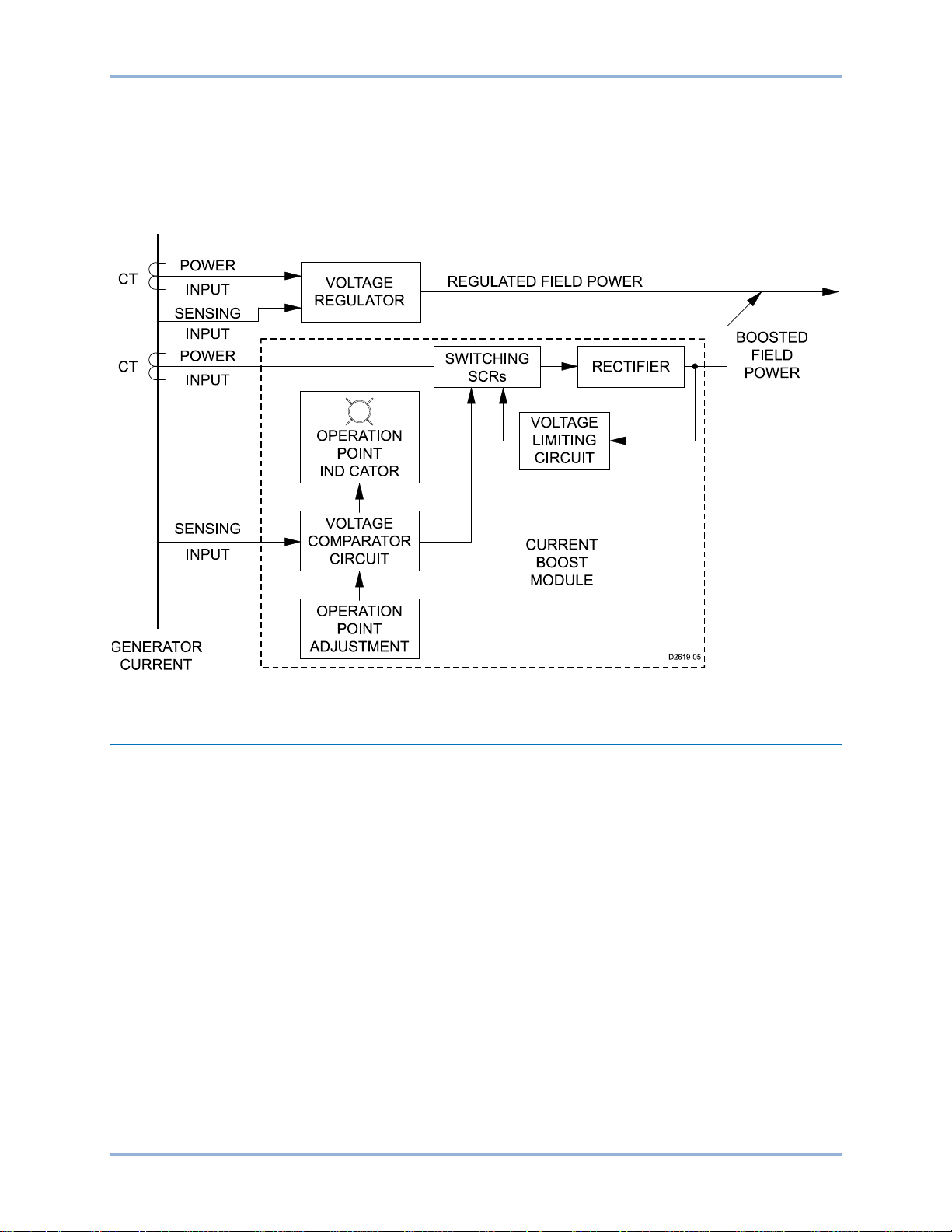
CBS 212Afunctions are illustrated in Figure 1 and described in the following paragraphs.
Figure 1. Function Block Diagram
Current Boost Module
The Current Boost Module rectifies the ac current received from the CTs and provides dc current boost to
the generator exciter field.
During normal generator operation, power from the generator output provides sufficient exciter field power
and the CBS 212A remains dormant. During normal operation, the CTs are effectively shorted by the
internal SCRs of the CBS 212A. Normal generator operation is indicated by the Operating Point Indication
LED being lit.
If the generator output voltage decreases below the operating-point setting, the CBS 212 A detects the
voltage drop, turns off the Operating Point Indication LED, and removes the SCR “short-circuit” from the
CTs. The CBS 212A then provides full current boost to the generator exciter until the voltage returns to a
level just above the operating point setting. The Controls and Indicators and Installation chapters provide
information about setting the Operating Point Adjustment.
An adjustable voltage limiting circuit prevents the Current Boost Module output from exceeding the
specified percentage of the nominal output voltage (60, 120, or 220 Vdc). The Output Limit Select
Jumpers are used to select the nominal output voltage (60, 120, or 220 Vdc) and the Output Limit
Adjustment is used to set the desired percentage of the nominal output voltage. The Output Limit
Adjustment is adjustable over a range of 50 to 100 percent of the jumper-selected nominal output voltage.
CBS 212A Functional Description
Page 10

4 9270700990 Rev F
Functional Description CBS 212A
Page 11

9270700990 Rev F 5
Call-Out
Description
A
Output Limit Adjustment. This screwdriver-adjus ted co ntrol is used to set the output
output limit.
B
Output Limit Select. The output limit is selected by positioning this pair of jumper wires at
to terminals TB2-7 and 8.
C
Sensing Voltage Select. The nominal sensing voltage is selected by positioning this jumper
connections at terminals TB2-10 and 11 select 120 Vac sensing voltage.
Controls and Indicators
CBS 212A controls and indi c ators consist of screwdriver-adjusted controls, jumper wires, and an indicator
light. See Figure 2. The call-outs (A, B, C, D, and E) of Figure 2 are listed in Table X along with a
description of each component.
Figure 2. Controls and Indicators
Table 1. Component Descriptions
voltage limit of the CBS 212A. The adjustment range is 50 to 100 percent of the selected
the appropriate terminals. Nominal output limits of 60, 120, or 220 Vdc can be selected by
repositioning the jumper wires. Jumper wire connections at TB2-1 and 2 select a 220 volt
output limit, connections at TB2-3 and 4 select a 120 volt limit, and connections at TB2-5
and 6 select a 60 volt limit. The other ends of the jumper wires must always be connected
wire. Nominal sensing voltage levels of 120 Vac or 240 Vac can be selected. Jumper wire
connections at terminals TB2-9 and 11 select 240 Vac sensing voltage. Jumper wire
CBS 212A Controls and Indicators
Page 12

6 9270700990 Rev F
Call-Out
Description
D
Operating Point Indication. This LED is lit during normal generator operating conditions. It
Adjustment setting.
E
Operating Point Adjustment. This screwdriver-adjuste d c ontrol is used to set the lower limit
Note
turns off when the CBS 212A is providing current boost to the exciter field. The LED turns
on again when the generator output voltage increases above the Operating Point
(pickup point) of the generator output voltage. If the generator voltage decreases below
this setting, current boost is initiated until the generator voltage increases above the
dropout point. For 120 Vac nominal sensing, dropout occurs when the sensed generator
output voltage increases to 5 volts above the Operating Point Adjustment setting. For 240
Vac nominal sensing, dropout occurs when the sensed generator output voltage increas es
to 10 Vac above the Operating Point Adjustment setting.
An Operating Point Adjustment setting that is too close to the nominal
generator output voltage may cause oscillation of the output voltage. If
oscillation occurs, rotate the Operating Point Adjustment control
counterclockwise until the oscillation stops.
Controls and Indicators CBS 212A
Page 13

9270700990 Rev F 7
Installation
This chapter describes CBS 212A mounting, interconnections, and calibration.
Mounting
When installing a CB S 212A Current Boost System, provisions must be made for the mounting of the
Current Boost Module and the Current Transformers (CTs). The CBS 212A must be mounted where the
environmental conditions do not exceed the specifications given in the Specifications chapter.
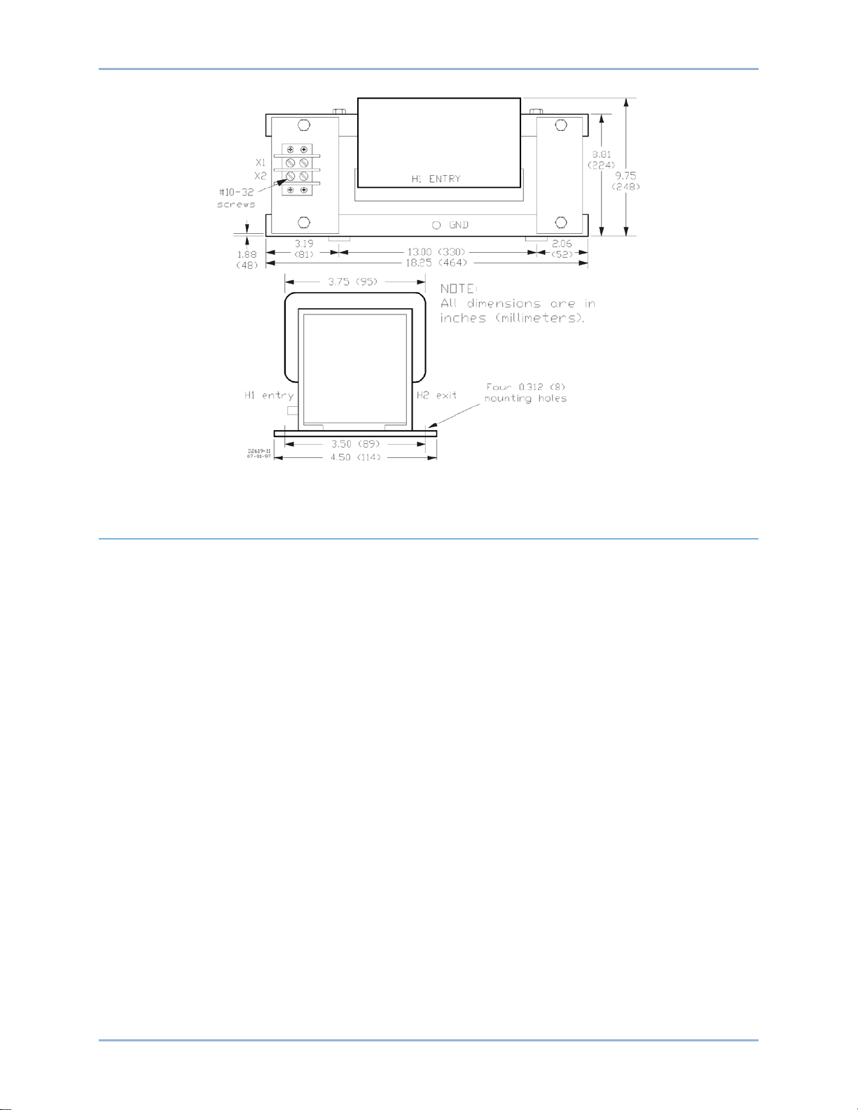
Current Boost Module
The Current Boost Module is convection cooled and should not be mounted near heat-generating
equipment or inside a totally enclosed cubicle where the temperature could exceed the operating limit.
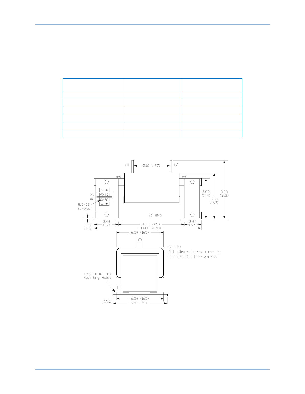
Vertical mounting is recommended to obtain optimum convection cooling. Mounting and panel drilling
dimensions are provided in Figure 3.
Figure 3. Outline and Panel Drilling Dimensions
CBS 212A Installation
Page 14
8 9270700990 Rev F
3-Phase Short-Circuit
Line Current *
BE25925001 †
1:8
125 to 250 A
BE25926001 †
1:17
250 to 500 A
BE25927001 †
1:34
500 to 1,000 A
BE25928001 †
1:69
1,000 to 2,000 A
BE25929001 †
1:138
2,000 to 4,000 A
BE25930001 †
1:277
4,000 to 8,000 A
Current Transformers (CTs)
Six standard CTs are available for 600 volt (or less) systems. The CTs should be mounted as close to the
generator output terminals as practical and before any load devices such as power transformers and
circuit breakers. Table 2 lists the available CTs and their corresponding ratios and short-circuit linecurrent ratings. Mounting and drilling dimensions for each of the six CTs are provided in Figures 4 through
9. For applications with system voltages higher than 600 volts, contact Basler Electric.
Table 2. CT Data
CT Part Number Turns Ratio
* All current values represent 300% short-circuit values.
† These CTs have pre-wound primary windings (no conductor window).
Installation CBS 212A
Figure 4. BE25925001 CT Dimensions
Page 15

9270700990 Rev F 9
Figure 5. BE25926001 CT Dimensions
Figure 6. BE25927001 CT Dimensions
CBS 212A Installation
Page 16

10 9270700990 Rev F
Figure 7. BE25928001 CT Dimensions
Figure 8. BE25929001 CT Dimensions
Installation CBS 212A
Page 17
9270700990 Rev F 11
Figure 9. BE25930001 CT Dimensions
Interconnection
Typical CBS 212A connections are shown in Figure 10.
CT Connections
When the CTs are connected as shown in CBS 212A, energy is supplied to the Current B oost Module
during the following fault conditions.
a. Symmetrical, three-phase short-circuit (A-phase to B-phase to C-phase)
b. A-phase to B-phase short-circuit
c. A-phase to C-phase short-circuit
d. B-phase to C-phase short-circuit
e. A-phase to Neutral short-circuit
f. B-phase to Neutral short-circuit
If the generator has a Neutral terminal, energy will be supplied to the CTs during conditions e and f.
During a C-phase to Neutral short-circuit, energy will not be supplied to the CTs. In this case, if the
voltage regulator is powered by phase A and phase B, the regulator may continue to supply power to the
exciter field.
Current Boost Module Connections
Current Boost Module connections are shown in CBS 212A. The Sensing Voltage Select jumper and the
Output Limit Select jumpers must be properly configured for your application. Information about
positioning these jumpers is provided in the following paragraphs of the Calibration sub-section.
CBS 212A Installation
Page 18

12 9270700990 Rev F
Figure 10. Interconnections
Installation CBS 212A
Page 19

9270700990 Rev F 13
Calibration
CBS 212A calibration consists of positioning the Sensing Voltage Select and Output Limit Select jumpers,
and adjusting the Output Limit Adjustment and Operating Point Adjustment controls. The following
procedures should be performed before placing the CBS 212A into service.
Sensing Voltage Selection
Configure the CBS 212A for the level of sensing voltage that will be applied to terminals TB1-3 and 4.
• For sensing voltage of 90 to 139 Vac, use the 120 Vac jumper position. Connect the Sensing
Voltage Selection jumper across terminals TB2-10 and 11.
• For sensing voltage of 180 to 277 Vac, use the 240 Vac jumper position. Connect the Sensing
Voltage Selection jumper across terminals TB2-9 and 11.
Output Limit Selection
Configure the CBS 212A for the level of field forcing voltage required to support a short-circuited
generator output.
1. Determine the level of field current required to sustain generator output during a short-circuit
condition. This value of current can be found in the generator manufacturer’s short-circuit
saturation data (plot of exciter field current versus line current with the generator output shortcircuited).
2. Obtain the hot exciter field resistance from the manufacturer’s data for your generator.
3. Calculate the Current Boost System field forcing voltage by multiplying the field current value
obtained in Step 1 by the resistance obtained in Step 2.
4. Position the Output Limit Select jumpers for the voltage range that most closely matches the field
forcing voltage calculated in Step 3. Jumper positions are summarized in the following
paragraphs.
• 60 Vdc Output Limit: jumper terminals TB2-7 to 5 and jumper terminals TB2-8 to 6.
• 120 Vdc Output Limit: jumper terminals TB2-7 to 3 and jumper terminals TB2-8 to 4.
• 220 Vdc Output Limit: jumper terminals TB2-7 to 1 and jumper terminals TB2-8 to 2.
Output Limit Adjustment
Set the output voltage limit of the CBS 212A. The Output Limit Adjustment control has an adjustment
range of 50 to 100 percent of the voltage selected by the Output Limit Selection jumpers.
A coarse adjustment of the CBS 212A output voltage limit can be made by approximation. The following
example illustrates the technique.
• If the desired voltage limit is 90 Vdc and the Output Limit Selection jumpers are in the 120 Vdc
position, set the Output Limit Adjustment control to the midpoint (halfway between 50 percent and
100 percent).
If a more precise setting of the output limit is desired, the adjustment must be performed during shortcircuit testing of the generator. Refer to the generator manufacturer’s recommended procedures for shortcircuit testing and perform the following steps.
1. Rotate the Output Limit Adjustment control fully counterclockwise.
2. Connect a dc voltmeter to terminals TB1-P (+) and N (–).
3. Apply a three-phase short-circuit to the generator output in accordance with the generator
manufacturer’s procedures .
4. While observing the voltmeter, slowly rotate the Output Limit Adjustment control clockwise until
the desired output voltage at terminals TB1-P and N is obtained.
CBS 212A Installation
Page 20

14 9270700990 Rev F
Operating Point Adjustment
Set the Operating Point Adjustment control at the level of generator voltage where the CBS 212A
provides current boost to the exciter field. Performing this procedure with the generator unloaded is the
preferred method for adjusting the opera tin g voltage level. If the generator load cannot be removed,
perform the steps listed under Loaded Generator.
Unloaded Generator
1. Rotate the Operating Point Adjustment control fully clockwise.
2. Remove all loads from the generator output.
3. Start the generator and bring it up to rated speed.
4. Lower the generator output voltage to the level where current boost is desired.
5. Slowly adjust the Operating Point Adjustment control counterclockwise until the Operating Point
Indication LED turns off (current boost is initiated).
6. Slowly increase the generator output voltage until the Operating Point Indication LED lights
(current boost is terminated).
7. Verify that the current-boost pickup and dropout levels are such that generator output voltage
oscillations will not occur.
Loaded Generator
1. De-energize the generator field and connect a jumper wire (10 AWG) across terminals TB1-1 and
2.
2. Perform Steps 3 through 7 of the Unloaded Generator sub-section.
3. Remove the jumper wire from terminals TB1-1 and 2 when calibration is complete.
Installation CBS 212A
Page 21

9270700990 Rev F 15
Testing
The procedures of this chapter can be used to verify proper installation of the CBS 212A and confirm the
calibration settings made in the calibration procedures of the Installation chapter. These procedures are to
be performed only after the CBS 212A has been installed and calibrated in accordance with the
instructions contained in the Installation chapter.
Installation Verification
Performing the following steps verifies proper CT selection and connection of the CBS 212A and CTs.
1. Ensure that the generator is not rotating.
2. Verify that the CBS 212A is connected in accordance with the interconnection diagram in the
Installation chapter.
3. Insert a 20 Aac ammeter in the conductor leading to terminal TB2-1 of the CBS 212A.
4. Start the generator and bring it up to rated speed.
5. Apply a nominal load to the generator. The C BS 2 12 A Operating Point Indication LED should be
lit (no current boost applied).
6. Note the ac current measured by the ammeter. The measured value should be approximately
equal to the calculated current value. The calculated current value is obtained using Equation 1.
𝐼𝐶= 𝐼𝐿× 1.73 ×
Equation 1. Calculated Current Value
1
𝑆
Where: IC is the calculated value
IL is the generator line current
S is the number of secondary turns for the selected CT. This value is obtained from
the CT Data table in the Installation chapter.
If the measured current and calculated current are dissimilar, recheck the generator data used for CT
selection and the CT connections.
Calibration Verificat ion
Verify proper CBS 212A calibration by performing the following steps. Performing this procedure with the
generator unloaded is the preferred method for verifying CBS 212A calibration. If the generator load
cannot be removed, perform the steps listed under Loaded Generator.
Unloaded Generator
1. Start the generator and bring it up to rated speed. The Operating Point Indication LED should
light (no current boost is applied).
2. Slowly reduce the generator output voltage until the Operating Point Indication LED turns off
(current boost is applied). The observed pickup level should match the Operating Point
Adjustment setting made during calibration (see Calibration in the Installation chapter).
3. Slowly increase the generator output voltage until the Operating Point Indication LED turns on
(current boost is withdrawn).
4. Verify that the current-boost pickup and dropout levels are such that generator output voltage
oscillations will not occur.
CBS 212A Testing
Page 22

16 9270700990 Rev F
Loaded Generator
1. De-energize the generator field and connect a suitably-sized jumper wire across terminals TB1-1
and 2.
2. Perform Steps 1 through 4 of the Unloaded Generator sub-section.
3. Remove the jumper wire from terminals TB1-1 and 2 when calibration verification is complete.
Power Verification
To verify that the C BS 212A will provide the specified boost current during short-circuit operation, refer to
the generator manufacturer’s recommended procedures for generator testing under short-circuit
conditions. If desired, final adjustment of the Output Limit Adjustment control may be made during shortcircuit testing.
Testing CBS 212A
Page 23

9270700990 Rev F 17
Specifications
CBS 212A Current Boost Systems have the following features and capabilities.
Operational Specifi c a ti ons
Output Power
Voltage ....................................... 60/120/220 Vdc (controlled by position of Output Limit Select jumpers)
Current ....................................... 20 Adc
Sensing Voltage
Nominal Level ............................ 120/240 Vac (jumper selectable)
Frequency .................................. 50/60 Hz
Voltamperes ............................... 10 VA
Output Limiting
Output Selection ......................... 60, 120, or 220 Vdc (jumper selectable)
Adjustment Range ...................... 50 to 100% of selected output
Operation Point Adjustment Range
120 V Nominal ............................ 70 to 131 Vac
240 V Nominal ............................ 140 to 262 Vac
Dropout Ratio
120 V Nominal ............................ 5 V above pickup point
240 V Nominal ............................ 10 V above pickup point
Power Dissipation
At Continuous Rating ................. < 50 W
General Specifications
Type Tests
Shock ......................................... 15 G in each of three mutually perpendicular planes
Vibration ..................................... 5 to 26 Hz at 1.2 G
26 to 52 Hz at 0.036” (0.914 mm), double amplitude
52 to 260 Hz at 5 G
Temperature
Operating.................................... −40°F to 140°F (−40°C to 60°C)
Storage ....................................... −85°F to 185°F (−65°C to 85°C)
Знак ЕАС (соответствие евразийским нормам)
• TP TC 004/2011
• TP TC 020/2011
Данный продукт рассчитан на 20 лет эксплуатации и хранения при условии соблюдения
инструкций настоящего руководства.
CBS 212A Specifications
Page 24

18 9270700990 Rev F
Weight
Current Boost Module ................ 15 lb (6.8 kg)
CT BE25925-001 ....................... 84 lb (38.1 kg)
CT BE25926-001 ....................... 78 lb (35.4 kg)
CT BE25927-001 ....................... 66 lb (29.9 kg)
CT BE25928-001 ....................... 122 lb (55.3 kg)
CT BE25929-001 ....................... 73 lb (33.1 kg)
CT BE25930-001 ....................... 50 lb (22.7 kg)
Specifications CBS 212A
Page 25

9270700990 Rev F 19
Revision History
The following information provides a historical summary of the changes made to the C BS 212 A instruction
manual (9270700990 Rev F). Revisions are listed in chronological or der.
Manual
Revision and Date
—, Nov-01
A
B
C
D
E
F, Apr-15
• Initial release
• No data available
• No data available
• No data available
• No data available
• Formatted manual to new style
• Added list of figures and tables to Introduction
• Corrected the CT metric weights stated in Specifications
• Renamed section from Controls and Indicators to Human-
Machine-Interface
• Added HMI diagram, Figure 3-1
• Revised Table 3-1 with call-outs to Section 3
• Renamed section from Installation to Calibration and Installation
• Corrected metric dimensions in Figure 4-1
• Added mounting hole dimensions to Figure 4-1
• Revised the procedures of the Calibration sub-section
• Renamed section from Operational Test to Testing
• Moved Replacements Parts from section 5 to new section 6
• Converted manual to new style
• Added EAC Certification
Change
CBS 212A Revision History
Page 26

20 9270700990 Rev F
Revision History CBS 212A
Page 27

Page 28

www.basler.com
12570 State R oute 143
Highland IL 62249-1074 USA
Tel: +1 618.654.23 4 1
Fax: +1.618. 654.2351
email: info@basler.com
P.A.E. Les Pins
67319 Wasselonne Cedex
FRANCE
Tel: +33 3.88.87.1010
Fax: +33 3.88. 87.0808
email: franceinfo@basler.com
No. 59 Heshun Road Loufeng D istrict (N)
Suzhou Indus trial Park
215122 Suzhou
P.R. CHINA
Tel: +86 512. 8227.2880
Fax: +86 512.8227.2887
email: chinainfo@basler.com
111 North Bridge Road
15-06 Peninsul a Plaz a
Singapore 1 79098
Tel: +65 68.4 4.6445
Fax: +65 68.44.8902
email: singaporeinfo@basler.com
 Loading...