

Page 1
www.basler.com
+1 618.654.2341 (USA)
info@basler.com
INTRODUCTION
BE3 frequency relays provide frequency monitoring and
protection in both single- and three-phase systems. They
are used in applications such as utility mains failure,
regulation of power supplies, and to protect generators
against over or underspeed. Underfrequency, overfrequency, and combined under/overfrequency units are
available. BE3 frequency relays operate when the
adjustable trip point is reached. A time delay control is
provided with an adjustment of 0 to 10 seconds (relay
operating time is typically 200 ms). This time delay may be
used to prevent false tripping when there are slight
variations in the voltage supply. On overfrequency units, the
output relay energizes when the input signal exceeds the
trip point. On underfrequency units, the output relay deenergizes when the input signal falls below the trip point. A
red LED indicates the state of the relay. A green LED
indicates the condition of the power supply.
SPECIFICATIONS
Operating Power
All units are self powered.
Nominal Voltage: 120 Vac, 240 Vac, 380 Vac,
or 480 Vac
Frequency: 50 Hz, 60 Hz, or 400 Hz
Burden: <2.5 VA per phase
Overload: 1.25 times nominal continuously.
2 times nominal for 3 s.
Setpoint
Over/Underfrequency Set Range
50 Hz Nominal: Adjustable 40 to 60 Hz
60 Hz Nominal: Adjustable 50 to 70 Hz
400 Hz Nominal: Adjustable 360 to 440 Hz
Setpoint range accuracy is ±3%.
Time Delay
Adjustable 0 to 10 s
Repeatability
Greater than 0.5% of full span
Differential
Fixed at 1% of nominal
Operating Time
200 ms typical
Output
Relay Type: D.P.D.T.
AC Rating: 250 V, 5 A, non-resistive,
1,200 VA
DC Rating: 125 V, 1 A, resistive, 120 W
Mechanical Life: 5 million operations
Model
BE3-81OT, BE3-81UT,
and BE3-81OT/UT
Temperature
Operating Temperature: 0°C (32°F) to 60°C (140°F)
Functional Temperature: –25°C (–13°F) to 70°C (158°F)
Storage Temperature: –40°C (–40°F) to 70°C (158°F)
Temperature Coefficient: 0.03% per °C (300 ppm/°C)
Humidity
Relative Humidity: 95% non-condensing
Physical
Mounting: DIN rail 1.38” by 0.29” (35 mm by
7.5 mm)
Case: Complies with IEC 529, DIN
40050, BS 5490
Case Material: Complies with UL 94VO
Weight
Single Function: 0.88 lb (0.4 kg)
Multiple Function: 1.32 lb (0.6 kg)
Size
Single Function: 2.17” wide (55 mm)
Multiple Function: 3.93” wide (100 mm)
Agency
cULus listed to UL 508 and CSA C22.2 No. 14
CE compliant
GOST-R certified per the relevant standards of Gosstandart
of Russia
OPERATION
BE3-81OT and BE3-81UT frequency relays have two useradjustable controls marked SET and DELAY. The BE381OT/UT has four controls: UNDER SET, OVER SET,
UNDER DELAY, and OVER DELAY. Each SET control
adjusts a relay trip point. An overfrequency trip causes the
relay output to energize when the frequency rises above the
SET threshold. An underfrequency trip causes the relay
output to de-energize when the frequency decreases below
the SET threshold. Refer to the setpoint specifications for
overfrequency and underfrequency adjustment ranges. Time
delay is the amount of time that elapses after the trip point is
reached and when the output relay operates.
Setting Example
A BE3-81OT relay with a nominal input rating of 60 Hz has
the following settings:
• SET - 65 Hz
• DELAY - 2 s
A trip occurs when the sensed frequency rises above 65
hertz and 2 seconds elapse. The relay resets when the
frequency decreases below 64.4 hertz (1% of nominal below
the setpoint).
Publication
9321800990
Revision
C
Instructions
Date
04/14
Copyright
2014
Page 2
INSTALLATION
BE3 frequency relays are designed for mounting on
standard DIN rails that comply to DIN-EN 50022. Mounting
involves hooking the top edge of the cutout on the base of
the case over one edge of the DIN rail. The opposite side of
the cutout containing the release clip is then pushed over
the opposite side of the DIN rail. To remove or reposition the
relay, lever the release clip and move the relay as required.
BE3 relays should be installed in a dry, vibration-free
location where the ambient temperature does not exceed
the operating temperature range. Connections to the relay
should be made using wire that meets applicable codes and
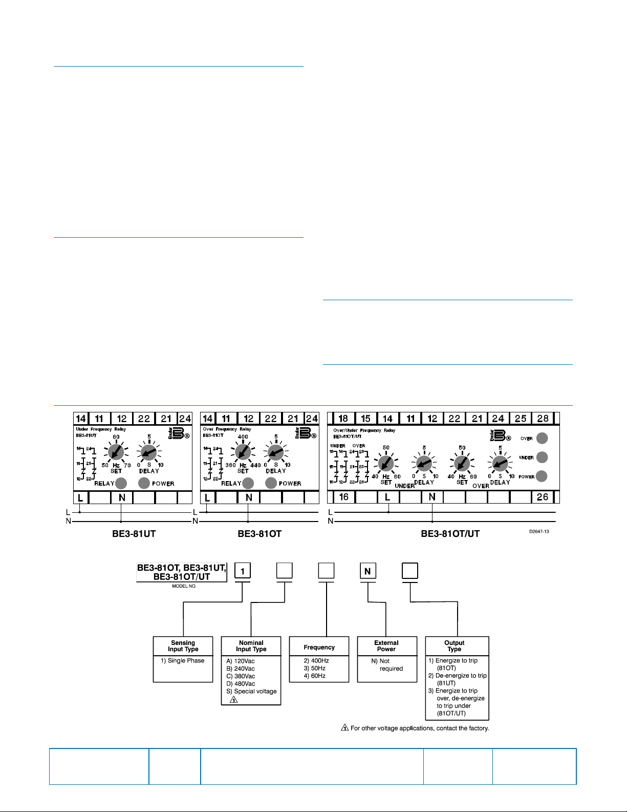
is properly sized for the application. Figure 1 shows the
terminal connections for the BE3-81OT, BE3-81UT, and
BE3-81OT/UT relays.
CALIBRATION
The calibration marks on the faceplate have a maximum
error of 10% and are provided only as guides. Proper
calibration requires using an accurate frequency meter in
parallel with the input signal. Use the following procedure to
calibrate your relay.
Overfrequency
1. Adjust the SET control fully clockwise and the DELAY
control fully counterclockwise.
2. Apply the desired trip frequency to the relay.
3. Slowly (allow for the 20 ms operating time) adjust the
SET control counterclockwise until the relay tr ips .
FIGURES
4. Set the DELAY control to the desired time delay and
apply nominal frequency to the relay.
5. Apply trip frequency to the relay and measure the time
to trip.
6. Adjust the DELAY and repeat Steps 4 and 5 until the
desired time delay is achieved.
Underfrequency
1. Adjust the SET and DELAY controls fully
counterclockwise.
2. Decrease the applied frequency from the nominal value
until the desired tripping frequency is reached.
3. Slowly adjust the SET control clockwise until the relay
trips.
4. Set the DELAY control to the desired time delay and
apply nominal frequency to the relay.
5. Step down the applied voltage from nominal to a level
just below the trip level set in Step 3 and measure the
time delay.
6. Adjust the DELAY and repeat Steps 4 and 5 until the
desired time delay is achieved.
MAINTENANCE
BE3 relays are solid-state devices that require no
maintenance. In the event that your relay requires repair,
contact Basler Electric, Highland, IL, USA for return
authorization.
ORDERING INFORMATION
Figure 2 shows the BE3 frequency relay style number
identification chart.
Publication
9321800990
Figure 1. BE3-81O, BE3-81U, and BE3-81O/U Input Connections
Figure 2. BE3-81O, BE3-81U, and BE3-81O/U Style Number Identification Chart
Revision
C
Instructions
Date
04/14
Page
2 of 2
 Loading...