

Page 1
www.basler.com
+1 618.654.2341 (USA)
info@basler.com
INTRODUCTION
The BE3-76SH dc overcurrent relay provides overcurrent
protection in dc circuits found in applications such as the
excitation field of a synchronous machine, transit systems,
and dc substation systems. The BE3-76SH utilizes a usersupplied 50 mV or 100 mV shunt to quickly detect excessive
dc current. When the monitored current exceeds the useradjustable setpoint and the user-adjustable inverse time
delay expires, a set of DPDT output contacts changes state
and the red RELAY LED lights. A green POWER LED
indicates the presence of relay operating power.
SPECIFICATIONS
Operating Power
Voltage (Style xxxAx): 90 to 150 Vac
Voltage (Style xxxBx): 180 to 300 Vac
Frequency: 45 to 65 Hz
Burden: <2 VA
Sensing Input
Rated Value: 50 mVdc (style xFxxx)
100 mVdc (style xGxxx)
Input Impedance: 50 kΩ
Source Impedance: 100 Ω maximum
Overload: 10 times input continuously
Setpoint
Overcurrent Range: 40 to 120% (±3%) of nominal
shunt input
Differential: Fixed at 5%
Repeatability: <0.5% of full span
Time Dial: 0.1 to 20
Relay Output
Relay Type: D.P.D.T.
AC Rating: 250 V, 5 A, non-resistive,
1,200 VA
DC Rating: 125 V, 1 A, resistive, 120 W
Mechanical Life: 5 million operations
Environment
Temperature
Operating: 0°C (32°F) to 60°C (140°F)
Functional: –25°C (–13°F) to 70°C (158°F)
Storage: –40°C (–40°F) to 70°C (158°F)
Coefficient: 0.03% per °C (300 ppm/°C)
Humidity
Relative: 95% non-condensing
Enclosure
Complies with DIN-EN 50022, BS 5584, any position. Case
material complies with UL 94 VO.
Size: 55 mm (2.17 in)
Model
Weight: 400 g (14.1 oz)
Mounting: DIN rail, 35 by 7.5 mm
Enclosure Code
Case: IP 50
Terminals: IP 30
Applicable Standards
General
IEC 144, BS 5420, VDE/VDI 0435, IEC 947, EN 60947
Safety
BS EN 61010, DIN 57411, VDE 0411, ANSI C37
Surge Withstand
IEC 801, EN 55020, ANSI C37-90a
Radio Frequency Interference
RFI degree N, complies with VDE 0875
cULus
cULus listed to UL 508 and CSA C22.2 No. 14
CE Compliance
This product meets or exceeds the standards required for
distribution in the European Community.
GOST-R Certification
GOST-R certified per the relevant standards of Gosstandart
of Russia.
BE3-76SH
OPERATION
BE3-76SH relays have two user-adjustable controls: SET
and TIME DIAL.
The SET control defines the level of dc current that causes
the BE3-76SH to trip. The SET control has an adjustment
range of 40 to 120% (±3%) of the nominal shunt rating.
The TIME DIAL control defines the time delay from when the
monitored dc current reaches the trip point and the output
contacts change state. The TIME DIAL control has an
adjustment range of 0.1 to 20.
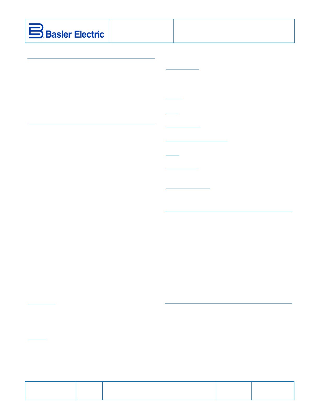
The settings of the SET and TIME DIAL controls are related
by an inverse function. See Figure 1. This means that the
higher the sensed current rises above the setting of the SET
control, the shorter the time to a relay trip. The TIME DIAL
setting is a linear multiplier for the time to a relay trip.
MOUNTING
BE3-76SH relays should be installed in a dry, vibration-free
location where the ambient temperature does not exceed
the operating temperature range.
BE3-76SH relays are designed for mounting on standard
DIN rails that comply with DIN-EN 50022. Mounting involves
hooking the top edge of the cutout on the base of the case
over one edge of the DIN rail. The opposite side of the
cutout containing the release clip is then pushed over the
opposite side of the DIN rail. To remove or reposition the
relay, lever the release clip and move the relay as required.
Publication
9409900990
Revision
D
Instructions
Date
04/14
Copyright
2014
Page 2
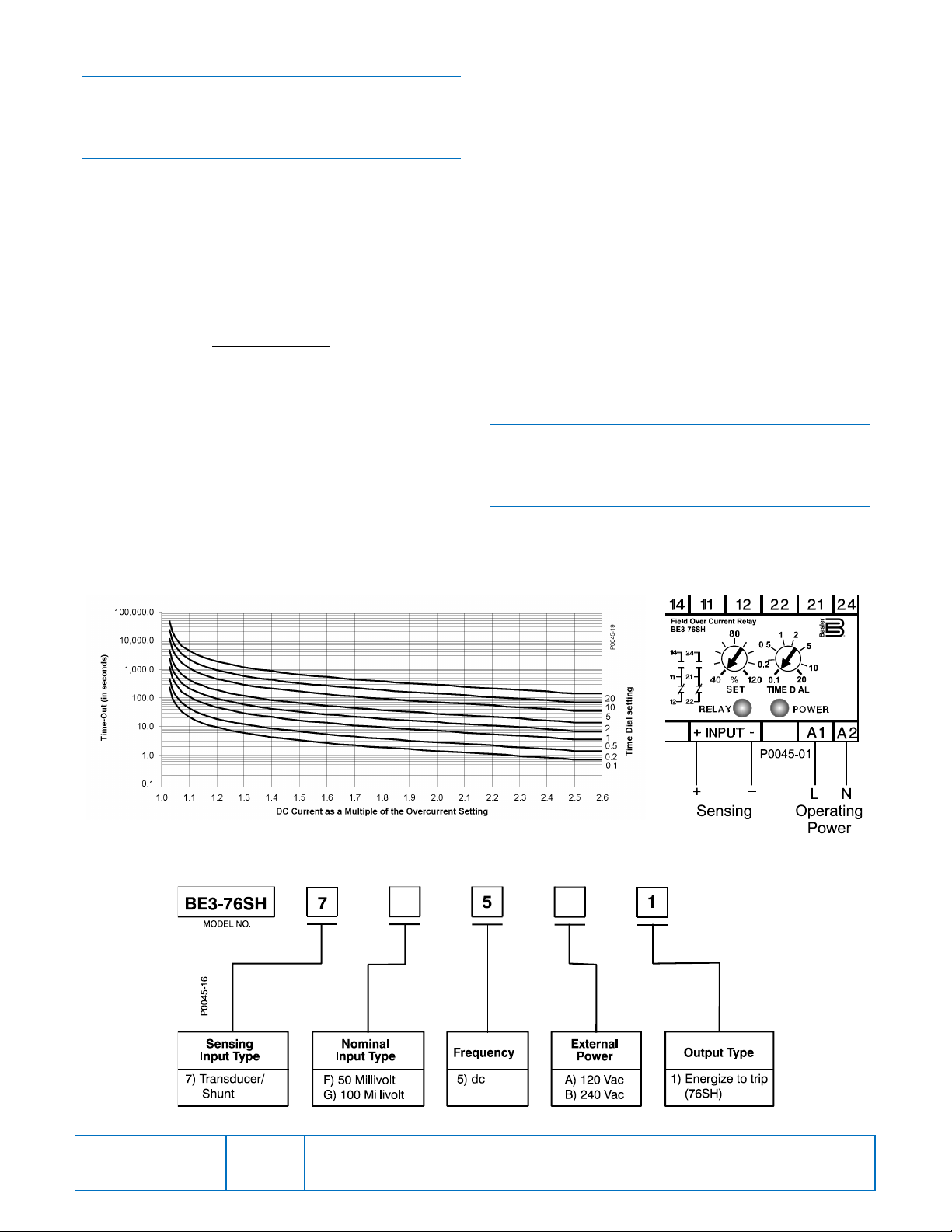
CONNECTIONS
and Connections
Relay connections should be made using wire that meets
applicable codes and is properly sized for the application.
Figure 2 shows the input connections for the BE3-76SH.
CALIBRATION
The calibration marks on the faceplate have a maximum
error of 10% and are provided only as guides. Proper
calibration requires using an accurate millivolt meter in
parallel with the input signal. When setting the relay, the
following performance conside r ation s shou ld be made to
determine the relay’s response to the various conditions
possible in a given application.
Multiple of Pickup (MoP)
The MoP ratio is determined by:
𝐴𝑐𝑡𝑢𝑎𝑙 𝑑𝑐 𝑐𝑢𝑟𝑟𝑒𝑛𝑡
𝑆𝑒𝑡 𝑐𝑜𝑛𝑡𝑟𝑜𝑙 𝑠𝑒𝑡𝑡𝑖𝑛𝑔
For example, if the relay SET control setting is the
equivalent of 100 Adc (the actual setting is expres sed as a
percentage of the rated, nominal sensing input) and the
actual current is 125 Adc, the MoP is 125/100 or 1.25.
Calibration Procedure
1. Rotate the SET control fully clockwise to the 120%
position and the TIME DIAL control fully
counterclockwise to the 0.1 position.
2. Apply the desired trip voltage to the relay, allowing for a
1.03 MoP factor.
FIGURES
3. Slowly rotate the SET control counterclockwise until the
RELAY LED starts flashing (allow for a 700 ms delay
before the LED lights). Then, slowly rotate the SET
control clockwise until the LED turns off.
4. Repeat Step 3 until the amount of rotation required
between LED turn-on and turn-off is minimal. The MoP
at this point will be 1.03.
Setting Example
The desired trip voltage in a 100 mV shunt application is
103 mVdc (103%).
When the SET control (expressed in %) is set above the
level of trip voltage, the MoP is below 1 and the relay is not
tripped.
When the setting value of the SET control equals the value
of trip voltage, the MoP is 1 and the relay is not tripped.
When the SET control setting is 100% (2.91% below the trip
voltage) the MoP is 1.03 so the relay time delay starts and
the RELAY LED starts flashing, but the relay is not tripped.
In this instance, the trip time delay is 244 seconds.
MAINTENANCE
BE3-76SH relays are solid-sta t e devi ces that require no
maintenance. In the event that your relay requires repair,
contact Basler Electric.
STYLE CHART
The BE3-76SH style identification chart is illustrated in
Figure 3.
Publication
9409900990
Figure 1. Inverse Time Characteristic Curves
Figure 3. BE3-76SH Style Chart
Revision
D
Instructions
Figure 2. Front Panel View
Date
04/14
Page
2 of 2
 Loading...