

Page 1
www.basler.com
info@basler.com
• UNDER DELAY - 5 s
• OVER DELAY - 5 s
INTRODUCTION
BE3 milliamp sensing alarm relays monitor analog signals
from transducers that measure current, voltage, watts, hertz,
vars, or power factor. These transducers are used to
indicate the status of a system or component. BE3-74T
relays operate when the adjustable trip point is reached. An
adjustable time delay is provided to avoid nuisance tripping
due to transient changes in sensed current. All BE3 milliamp
sensing alarm relays have a POWER LED to indicate the
condition of the power supply. BE3-74TL and BE3-74TH
relays have a RELAY LED to indicate the trip output status.
The BE3-74TD relay has an OVER LED to indicate
overcurrent trip and an UNDER LED to indicate an
undercurrent trip.
SPECIFICATIONS
Operating Power
All units require external operating power.
Nominal Voltage: 120 Vac, 240 Vac, 380 Vac, 480
Frequency: 45 to 65 Hz
Burden
Vac: 2 VA
Vdc: <3 W
Sensing Input
Nominal Current: 0 to 1 mA, 4 to 20 mA, or 0 to
Burden: 10 kΩ/V
Overload: 2 times nominal continuously or
Setpoint
Overcurrent Range: Adjustable 40 to 120% (±3%) of
Undercurrent Range: Adjustable 0 to 80% (±3%) of
Time Delay: Adjustable 0 to 10 s
Repeatability: Greater than 0.5% of full span
Differential: Fixed at 5% of nominal
Operating Time: 200 ms typical
Output
Relay Type: D.P.D.T.
AC Rating: 250 V, 5 A, non-resistive,
DC Rating: 125 V, 1 A, resistive, 120 W
Mechanical Life: 5 million operations
Temperature
Operating Temperature: 0°C (32°F) to 60°C (140°F)
Functional Temperature: –25°C (–13°F) to 70°C (158°F)
Storage Temperature: –40°C (–40°F) to 70°C (158°F)
Temperature Coefficient: 0.03% per °C (300 ppm/°C)
Humidity
Relative Humidity: 95% non-condensing
Publication
9321100990
+1 618.654.2341 (USA)
Vac, or 24 Vdc
20 mA (specify nominal range)
10 times nominal for 3 s
nominal
nominal
1200 VA
Revision
C
Instructions
Model
BE3-74TD, BE3-74TH,
and BE3-74TL
Physical
Mounting: DIN rail 1.38” by 0.29” (35 mm by
7.5 mm)
Case: Complies with IEC 529, DIN
40050, BS 5490
Case Material: Complies with UL 94VO
Weight
Single Function: 0.88 lb (0.4 kg)
Multiple Function: 1.32 lb (0.6 kg)
Size
Single Function: 2.17” wide (55 mm)
Multiple Function: 3.93” wide (100 mm)
Agency
cULus listed to UL 508 and CSA C22.2 No. 14
CE compliant
GOST-R certified per the relevant standards of Gosstandart
of Russia
OPERATION
BE3-74TH and BE3-74TL relays have two user-adjustable
controls marked SET and DELAY. The BE3-74TD relay has
four controls: UNDER SET, UNDER DELAY, OVER SET,
and OVER DELAY. The SET control adjusts the relay trip
point. An overcurrent trip causes the relay output to energize
when the current rises above the SET threshold. The
overcurrent SET level is adjustable from 40 to 120% (±3%)
of nominal input (I
output to de-energize when the current decreases below the
SET threshold. The undercurrent SET level is adjustable
from 0 to 80% (±3%) of I
time from when a fault is detected until the output contact s
change state. The DELAY control is adjustable from 0 to 10
seconds (200 ms typical operating time).
Setting Example
A BE3-74TD with a nominal input type of M (4 to 20 mA) has
the following settings:
• UNDER SET - 50%
An undercurrent condition is detected when the sensed
current decreases to 10 mA. The UNDER output deenergizes 5 seconds after the undercurrent condition is
detected. An overcurrent condition is detected when the
sensed current increases to 20 mA. The OVER output
energizes 5 seconds after the overcurrent condition is
detected.
INSTALLATION
BE3 dc milliamp sensing alarm relays are designed for
mounting on standard DIN rails that comply to DIN-EN
50022. Mounting involves hooking the top edge of the cutout
on the base of the case over one edge of the DIN rail. The
opposite side of the cutout containing the release clip is then
pushed over the opposite side of the DIN rail. To remove or
reposition the relay, lever the release clip and move the
relay as required. BE3 relays should be installed in a dry,
). An undercurrent trip causes the relay
nom
. The DELAY control adjusts the
nom
• OVER SET - 100%
Date
04/14
Copyright
2014
Page 2
vibration-free location where the ambient temperature does
not exceed the operating temperature range. Connections to
the relay should be made using wire that meets applicable
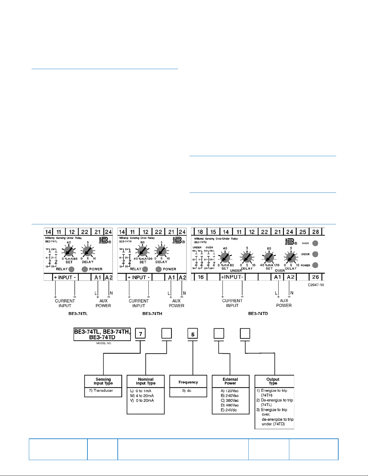
codes and is properly sized for the application. Figure 1
shows the input connections for the BE3-74TD, BE3-74TH,
and BE3-74TL relays.
CALIBRATION
The calibration marks on the faceplate have a maximum
error of 10% and are provided only as guides. Proper
calibration requires inserting an accurate milliammeter in
series with the input signal. Use the following procedure to
calibrate your relay.
Overcurrent Trip
1. Adjust the SET control fully clockwise and the DELAY
control fully counterclockwise. Apply nominal external
operating power to the relay.
2. Apply the desired trip current to the relay.
3. Slowly adjust the SET control counterclockwise until the
relay trips.
Overcurrent Delay
1. Set the DELAY control at the desired time setting. Apply
nominal external operating power to the relay.
2. Apply a value of current that is just above the trip
setpoint. Measure the time from when the current is
applied until the relay trips.
3. Compare the measured time to the desired time delay
and adjust the DELAY control accordingly.
FIGURES
4. Repeat Steps 2 and 3 as required.
Undercurrent Trip
1. Adjust the SET control and DELAY control fully
counterclockwise. Apply nominal external operating
power to the relay.
2. Apply the desired trip current to the relay.
3. Slowly adjust the SET control clockwise until the relay
trips.
Undercurrent Delay
1. Set the DELAY control at the desired time setting. Apply
nominal external operating power to the relay.
2. Apply a value of current that is above the trip setpoint.
Remove the applied current. Measure the time from
when the current is removed until the relay trips.
3. Compare the measured time to the desired time delay
and adjust the DELAY control accordingly.
4. Repeat Steps 2 and 3 as required.
MAINTENANCE
BE3 relays are solid-state devices that require no
maintenance. In the event that your relay requires repair,
contact Basler Electric, Highland, IL, USA for return
authorization.
ORDERING INFORMATION
Figure 2 shows the BE3 milliamp sensing alarm relay style
number identification chart.
Publication
9321100990
Figure 1. BE3-74TD, BE3-74TH, and BE-74TL Input Connections
Figure 2. BE3-74TD, BE3-74TH, and BE3-74TL Style Number Identification Chart
Revision
C
Instructions
Date
04/14
Page
2 of 2
 Loading...