

Page 1
INSTRUCTION MANUAL
FOR
OVERCURRENT RELAYS
BE1-50/51B-230/-234/-239
Publication: 9252000894
Revision: H 12/11
Page 2

Page 3

INTRODUCTION
This instruction manual provides information about the operation and installation of the BE1-50/51B-230,
BE1-50/51B-234, and BE1-50/51B-239 Overcurrent Relays. To accomplish this, the following information
is provided:
General Information and Specifications
Controls and Indicators
Functional Description
Installation and Maintenance
Testing
WARNING!
To avoid personal injury or equipment damage, only qualified personnel should
perform the procedures in this manual.
9252000894 Rev H BE1-50/51B-230/-234/-239 Introduction i
Page 4

First Printing: October 2006
Printed in USA
Copyright © 2006-2011 Basler Electric, Highland Illinois 62249 USA
All Rights Reserved
December 2011
CONFIDENTIAL INFORMATION
of Basler Electric, Highland Illinois, USA. It is loaned for confidential use,
subject to return on request, and with the mutual understanding that it will not
be used in any manner detrimental to the interest of Basler Electric.
It is not the intention of this manual to cover all details and variations in equipment, nor does this manual
provide data for every possible contingency regarding installation or operation. The availability and design
of all features and options are subject to modification without notice. Should further information be
required, contact Basler Electric.
BASLER ELECTRIC
12570 STATE ROUTE 143
HIGHLAND IL 62249 USA
http://www.basler.com, info@basler.com
PHONE +1 618.654.2341 FAX +1 618.654.2351
ii BE1-50/51B-230/-234/-239 Introduction 9252000894 Rev H
Page 5

REVISION HISTORY
The following information provides a historical summary of the changes made to this instruction manual
(9252000894). Revisions are listed in reverse chronological order.
Manual
Revision and Date
H, 12/11
G, 11/10
F, 12/08
E, 08/08
D, 05/08
C, 03/08
B, 11/07
A, 12/06
—, 10/06
Made changes to reflect that a new connection plug is included with
the relay.
Updated year of IEEE C37.90 specifications in Section 1.
Improved description of Locator B (Active/Pickup LED) in Table 2-1.
Removed all references to a connection plug supplied with relay.
Added year to IEEE specifications in Section 1.
Improved Figure 5-4 and Figure 5-8, Target Indicator Test Setup.
Added GOST-R Certification in Section 1.
Minor text edits in Section 3 and Section 5.
Added 9252000239 (5 amp relay with case).
Updated Figures 2-2, 2-3, and 2-4 to show new layout of SW3.
Minor corrections in Section 5, Testing.
Updated front panel drawings.
Added 9252000234 (1 amp relay).
Revised target current ranges stated throughout the manual.
Clarified continuous rating for the current sensing input. Added
derating graph.
Added IEEE C37.90.2 compliance for radiated interference.
Added cURus recognition.
Modified target testing procedure to provide individual testing of the
51 and 50-A targets.
Added publication number and revision level to the footer of each
page.
Initial release
Change
9252000894 Rev H BE1-50/51B-230/-234/-239 Introduction iii
Page 6

iv BE1-50/51B-230/-234/-239 Introduction 9252000894 Rev H
Page 7

CONTENTS
SECTION 1 • GENERAL INFORMATION ................................................................................................ 1-1
SECTION 2 • CONTROLS AND INDICATORS ........................................................................................ 2-1
SECTION 3 • FUNCTIONAL DESCRIPTION ........................................................................................... 3-1
SECTION 4 • INSTALLATION .................................................................................................................. 4-1
SECTION 5 • TESTING ............................................................................................................................ 5-1
APPENDIX A • CHARACTERISTIC CURVES ......................................................................................... A-1
9252000894 Rev H BE1-50/51B-230/-234/-239 Introduction v
Page 8

vi BE1-50/51B-230/-234/-239 Introduction 9252000894 Rev H
Page 9

SECTION 1 • GENERAL INFORMATION
TABLE OF CONTENTS
SECTION 1 • GENERAL INFORMATION ................................................................................................ 1-1
Introduction ............................................................................................................................................ 1-1
Features ................................................................................................................................................. 1-1
Advantages ........................................................................................................................................ 1-1
Specifications ......................................................................................................................................... 1-2
Time Overcurrent (51) Element .......................................................................................................... 1-2
Instantaneous Overcurrent A (50-A) Element .................................................................................... 1-2
Instantaneous Overcurrent B (50-B) Element .................................................................................... 1-3
Current Sensing Input ........................................................................................................................ 1-3
Frequency Response ......................................................................................................................... 1-5
Transient Response ........................................................................................................................... 1-5
Harmonic Rejection ............................................................................................................................ 1-5
Target Indicators ................................................................................................................................ 1-6
Output Contacts ................................................................................................................................. 1-6
Type Tests .......................................................................................................................................... 1-7
Agency Recognition ........................................................................................................................... 1-7
Environment ....................................................................................................................................... 1-7
Physical .............................................................................................................................................. 1-7
Figures
Figure 1-1. Current Sensing Input Derating Curve (BE1-50/51B-230/-239) ............................................. 1-3
Figure 1-2. Current Sensing Input Derating Curve (BE1-50/51B-234)
Figure 1-3. Current Sensing Input Burden (BE1-50/51B-230/-239)
Figure 1-4. Current Sensing Input Burden (BE1-50/51B-234)
Figure 1-5. Harmonic Rejection
...................................................... 1-4
.......................................................... 1-4
.................................................................. 1-5
................................................................................................................. 1-6
9252000894 Rev H BE1-50/51B-230/-234/-239 General Information i
Page 10

ii BE1-50/51B-230/-234/-239 General Information 9252000894 Rev H
Page 11

SECTION 1 • GENERAL INFORMATION
Introduction
BE1-50/51B-230, BE1-50/51B-234, and BE1-50/51B-239 relays provide non-directional, single-phase or
ground overcurrent protection and are direct replacements for General Electric IAC66K relays. The BE150/51B-230 and BE1-50/51B-239 have 5 ampere current sensing inputs. The BE1-50/51B-234 has a 1
ampere current sensing input. The BE1-50/51B-230 and BE1-50/51B-234 relays are supplied as draw-out
assemblies that plug directly into existing cases for IAC66K relays. The draw-out assemblies are supplied
with relay covers and adaptor plates for mounting the covers onto existing IAC66K cases. The BE150/51B-239 relay is a draw-out assembly supplied with a case and cover. A connection plug is supplied
with all models.
BE1-50/51B-230, BE1-50/51B-234, and BE1-50/51B-239 relays are self-powered, compatible with 50 or
60 Hz power systems, and have three protection elements: one time overcurrent (51) element and two
instantaneous overcurrent (50) elements. The 51 element offers timing characteristic curves similar to
those used by GE IAC and ABB relays.
Features
A wide range of pickup settings and front panel selectable time characteristics permit applications
involving coordination with fuses, reclosers, cold load pickup, motor starting, and fixed time requirements.
In addition, an integrating reset function is available to simulate the disk reset of electromechanical relays.
BE1-50/51B-230, BE1-50/51B-234, and BE1-50/51B-239 overcurrent relays have the following standard
features.
• Independent time and instantaneous elements
• A secure method to manually trip the breaker at the relay front panel
• Direct reading front panel controls
• Minimum pickup setting for safety during installation
• Time characteristics extend to a pickup multiple of 40
• Rugged draw-out construction
• Gravity latching targets retain indication without power
• Built-in accuracy eliminates internal adjustments
• Minimum transient overreach
• Field selectable characteristic curve selection similar to either GE IAC or ABB type curves
• Field selectable instantaneous or integrating reset
• Field selectable 50 or 60 Hz operation
• Field selectable 0.0 or 0.1 second, fixed, instantaneous delay
Internal switches provide for selecting system-operating frequencies of 50 or 60 Hz, instantaneous
element delays of 0.0 or 0.1 second, characteristic curve group selection for either GE IAC or ABB type
curves, and instantaneous or integrating reset characteristics. Switch location and description is provided
in Section 2.
Advantages
BE1-50/51B-230, BE1-50/51B-234, and BE1-50/51B-239 overcurrent relays have many advantages over
other overcurrent relays. The primary advantages are:
• Time characteristics are defined by equations and graphs
• Field selectable time characteristics
• Very low burden extends the linear range of the CTs
• Self powered from the sensed current
• Continuous automatic calibration
BE1-50/51B-230, BE1-50/51B-234, and BE1-50/51B-239 overcurrent relays may be tested without
removing the relay from the case. Shorting contacts are provided for all current inputs when the
connection plugs or relay chassis is removed from the relay case.
9252000894 Rev H BE1-50/51B-230/-234/-239 General Information 1-1
Page 12

Specifications
BE1-50/51B-230, BE1-50/51B-234, and BE1-50/51B-239 electrical and physical specifications are listed
in the following paragraphs.
Time Overcurrent (51) Element
BE1-50/51B-230/-239 Pickup
Setting Range ............................ 0.5 to 15.9 Aac
Setting Increment ....................... 0.1 Aac
Accuracy .................................... Sum of ±2% and ±25 mAac
BE1-50/51B-234 Pickup
Setting Range ............................ 0.1 to 3.18 Aac
Setting Increment ....................... 0.02 Aac
Accuracy .................................... Sum of ±2% and ±5 mAac
Dropout
Dropout occurs at 95% of pickup value.
Characteristic Curves
Available curve types follow IEEE Standard C37.112 (1996) and emulate standard GE IAC, ABB CO, and
BS142 curves. Appendix A, Characteristic Curves illustrates the available curves and lists the applicable
constants.
Curve Types .............................. Short Inverse, Long Inverse, Definite Time, Moderately Inverse, Inverse,
Very Inverse, Extremely Inverse, BS142 Very Inverse, BS142 Extremely
Inverse, Fixed Time
Time Multiplier ........................... 11 curves for each characteristic
Timing Accuracy ........................ ±1 cycle, ±2%. This accuracy applies to the range of 1.3 to 40 times tap
and is for a given measured multiple of tap.
Fixed Timing
Setting Range ............................ 0.1 to 9.9 s
Setting Increment ....................... 0.1 s
Timing Accuracy ........................ ±1 cycle, ±2% of the time to trip for time dial settings ≥0.1.
Reset
Integrating .................................. Simulates the disk reset of electromechanical relays and begins when
the current decreases below 95% of pickup. Appendix A, Characteristic
Curves illustrates the integrating reset characteristic curve and equation.
Instantaneous ............................ Reset occurs within 16 ms of when the current decreases below 95% of
the pickup level.
Instantaneous Overcurrent A (50-A) Element
BE1-50/51B-230/-239 Pickup
Setting Range ............................ 2 to 99 Aac
Setting increment ....................... 1 Aac
Accuracy .................................... Sum of ±2% and ±25 mAac
BE1-50/51B-234 Pickup
Setting Range ............................ 0.4 to 19.8 Aac
Setting increment ....................... 0.2 Aac
Accuracy .................................... Sum of ±2% and ±5 mAac
Dropout
Dropout occurs at 95% of pickup value.
Time Delay
Switch selectable—no intentional delay (SW3-2 open/off) or a fixed delay of 100 ms (SW3-2 closed/on).
Appendix A, Characteristic Curves illustrates the characteristic curve for the 50-A and 50-B elements.
1-2 BE1-50/51B-230/-234/-239 General Information 9252000894 Rev H
Page 13
Instantaneous Overcurrent B (50-B) Element
Continuous Current
Current Sensing Input
0
2
4
6
8
10
12
14
16
-40 -20 0 20 40 60
Ambient Temperature (C)
Current (Aac)
BE1-50/51B-230/-239 Pickup
Setting Range ............................ 1 to 15.9 Aac
Setting increment ....................... 0.1 Aac
Accuracy .................................... Sum of ±2% and ±25 mAac
BE1-50/51B-234 Pickup
Setting Range ............................ 0.2 to 3.18 Aac
Setting increment ....................... 0.02 Aac
Accuracy .................................... Sum of ±2% and ±5 mAac
Dropout
Dropout occurs at 95% of pickup value.
Time Delay
Fixed at no intentional delay. Appendix A, Characteristic Curves illustrates the characteristic curve for the
50-A and 50-B elements.
Reset Characteristic
Resets within 16 ms of when sensed current decreases below the pickup level.
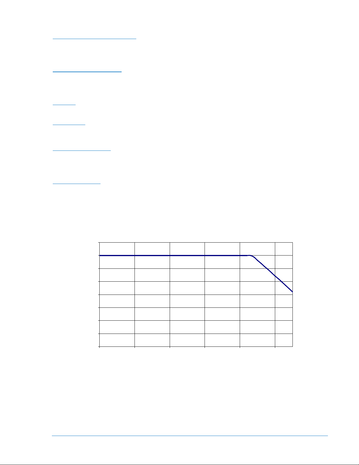
Current Sensing Input
BE1-50/51B-230
Continuous Rating ..................... 14 Aac∗
1 Second Rating ........................ 400 Aac
∗ Continuous rating is 14 Aac for temperatures up to 45°C. See Figure 1-1 for derating curve.
Figure 1-1. Current Sensing Input Derating Curve (BE1-50/51B-230/-239)
9252000894 Rev H BE1-50/51B-230/-234/-239 General Information 1-3
Page 14
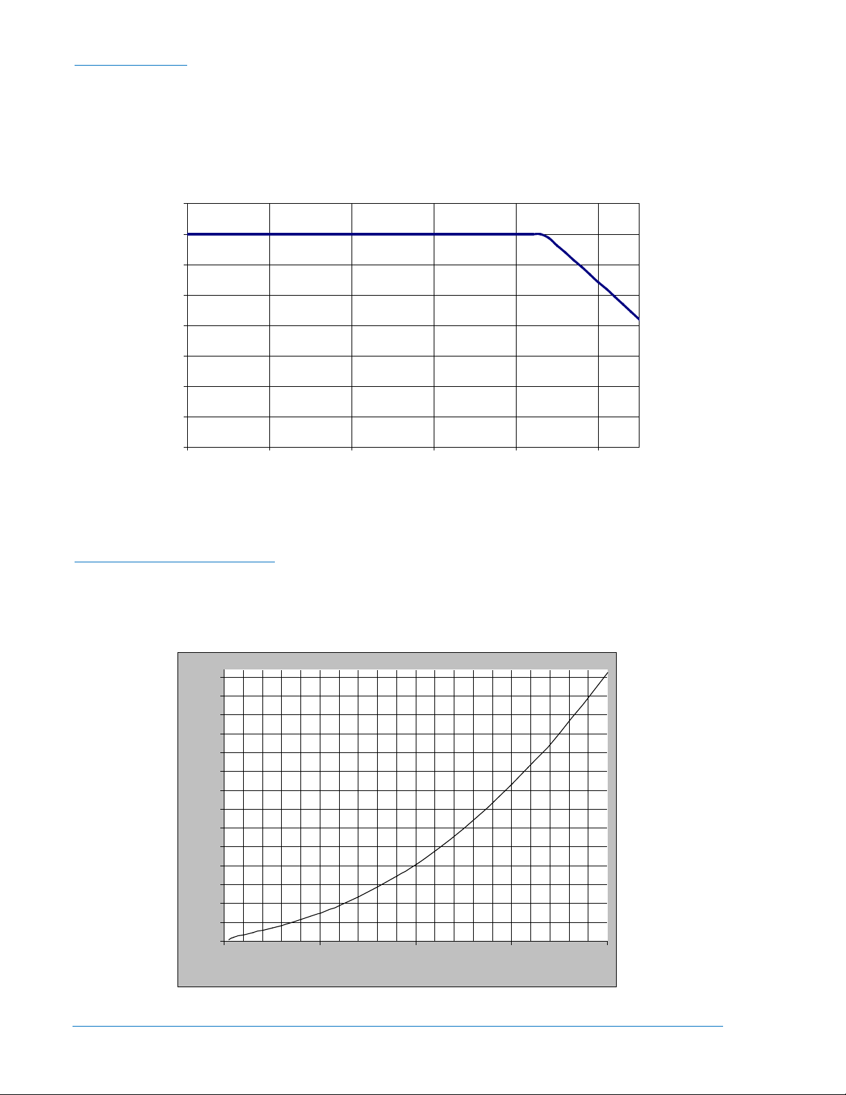
BE1-50/51B-234
Continuous Current
Current Sensing Input
0
0.4
0.8
1.2
1.6
2
2.4
2.8
3.2
-40 -20 0 20 40 60
Ambient Temperature (C)
Current (Aac)
BE1-50/51B-230/-239 CT Burden
0
10
20
30
40
50
60
70
80
90
100
110
120
130
140
0 10 20 30 40
Input Current (Amps)
Burden in VA (rms)
Continuous Rating ..................... 2.8 Aac∗
1 Second Rating ........................ 80 Aac
∗ Continuous rating is 2.8 Aac for temperatures up to 45°C. See Figure 1-2 for derating curve.
Figure 1-2. Current Sensing Input Derating Curve (BE1-50/51B-234)
BE1-50/51B-230/-239 Burden
Figure 1-3
At 0.5 Aac .................................. 2.8 Ω
At 5.0 Aac .................................. 0.3 Ω
1-4 BE1-50/51B-230/-234/-239 General Information 9252000894 Rev H
illustrates the current sensing input burden characteristic.
Figure 1-3. Current Sensing Input Burden (BE1-50/51B-230/-239)
Page 15

BE1-50/51B-234 Burden
BE1-50/51B-234 CT Burden
0
10
20
30
40
50
60
70
80
90
0 1 2 3 4 5 6 7 8
Input Current (Amps)
Burden in VA (rms)
Figure 1-4
At 0.1 Aac .................................. 57.0 Ω
At 1.0 Aac .................................. 6.9 Ω
illustrates the current sensing input burden characteristic.
Figure 1-4. Current Sensing Input Burden (BE1-50/51B-234)
Frequency Response
A change of ±5 Hz from the nominal 50/60 Hz current causes <0.5% change in the current required for
pickup.
Transient Response
<10% overreach with system time constants up to 40 ms.
Harmonic Rejection
Rejection of odd and even harmonics is illustrated in Figure 1-5.
9252000894 Rev H BE1-50/51B-230/-234/-239 General Information 1-5
Page 16
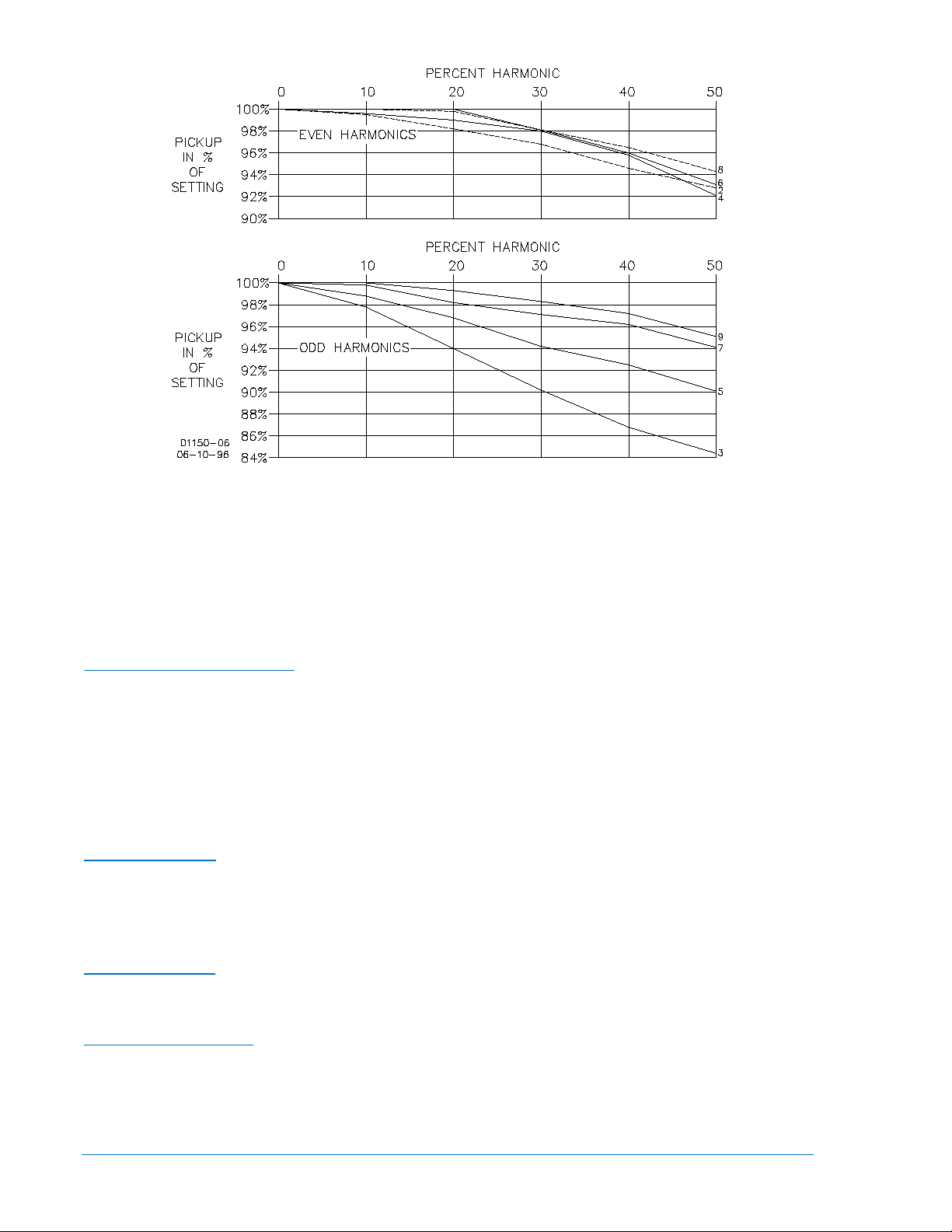
Figure 1-5. Harmonic Rejection
Target Indicators
A gravity-latched, manually-reset, current-operated target indicator is provided for the time-overcurrent
(51) trip output and the instantaneous overcurrent A (50-A) trip output. A target indicator is not provided
for the 50-B trip output. The level of trip circuit current required to operate each target is individually
controlled by a circuit board jumper. See Section 2, Controls and Indicators for jumper locations and
function assignments
Minimum Operating Current
Jumper Position—Pins 1 and 2: 0.9 to 2.25 A ∗
Jumper Position—Pins 2 and 3: 80 mA to 200 mA ∗
∗ Minimum operating current values. See Output Contacts for the maximum acceptable levels of trip
circuit currents.
Output Contacts
Each protective element (51, 50-A, and 50-B) is equipped with a set of Form A contacts rated for tripping
duty.
Resistive Ratings
120/240 Vac ............................... Make 30 amperes for 0.2 seconds, carry 7 amperes for 2 minutes, 3
amperes continuously, and break 5 amperes.
125/250 Vdc ............................... Make 30 amperes for 0.2 seconds, carry 7 amperes for 2 minutes, 3
amperes continuously, and break 0.3 ampere.
Inductive Ratings
120/240 Vac, 125/250 Vdc ........ Make and carry 30 amperes for 0.2 seconds, carry 7 amperes for 2
minutes, 3 amperes continuously, and break 0.3 ampere. (L/R = 0.04).
Terminal Assignments
51 Element ................................. 1, 2
50-A Element ............................. 1, 3
50-B Element ............................. 9, 10
1-6 BE1-50/51B-230/-234/-239 General Information 9252000894 Rev H
Page 17

Type Tests
Isolation ..................................... IEEE C37.90-2005
Transient Surge ......................... IEEE C37.90.1-2004
Radiated Interference ................ IEEE C37.90.2-2004
Electrostatic Discharge .............. IEEE C37.90.3-2006
Vibration ..................................... IEC 255-21-1
Shock and Bump ....................... IEC 255-21-2
Agency Recognition
cURus
cURus recognition per UL Standard 508, File E97035 and CSA Standard C22.2 No. 14.
GOST-R Certification
GOST-R certified per the relevant standards of Gosstandart of Russia.
Environment
Operating Temperature ............. –40 to 70°C (–40 to 158°F)
Storage Temperature ................ –50 to 70°C (–58 to 158°F)
Physical
Weight ........................................ 6.1 lb (2.77 kg)
9252000894 Rev H BE1-50/51B-230/-234/-239 General Information 1-7
Page 18

1-8 BE1-50/51B-230/-234/-239 General Information 9252000894 Rev H
Page 19

SECTION 2 • CONTROLS AND INDICATORS
TABLE OF CONTENTS
SECTION 2 • CONTROLS AND INDICATORS ........................................................................................ 2-1
Introduction ............................................................................................................................................ 2-1
Front Panel Controls and Indicators ...................................................................................................... 2-1
Circuit Board Controls ............................................................................................................................ 2-3
Figures
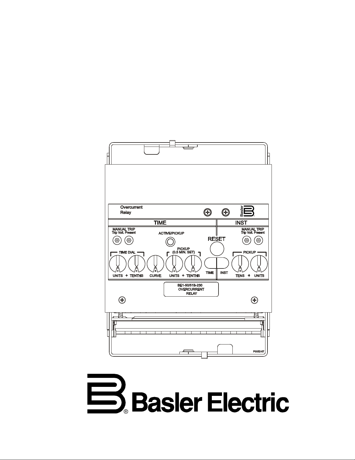
Figure 2-1. Front Panel Controls and Indicators ....................................................................................... 2-1
Figure 2-2. Circuit Board Controls
Figure 2-3. View of 50-B Pickup Selector Switches (BE1-50/51B-230/-239)
Figure 2-4. View of 50-B Pickup Selector Switches (BE1-50/51B-234)
Tables
Table 2-1. Front Panel Controls and Indicators ......................................................................................... 2-2
Table 2-2. Circuit Board Controls
............................................................................................................. 2-3
............................................ 2-5
.................................................... 2-5
.............................................................................................................. 2-4
9252000894 Rev H BE1-50/51B-230/-234/-239 Controls and Indicators i
Page 20

ii BE1-50/51B-230/-234/-239 Controls and Indicators 9252000894 Rev H
Page 21
SECTION 2 • CONTROLS AND INDICATORS
Introduction
BE1-50/51B-230, BE1-50/51B-234, and BE1-50/51B-239 relay controls and indicators are located on the
front panel and circuit board.
Front Panel Controls and Indicators
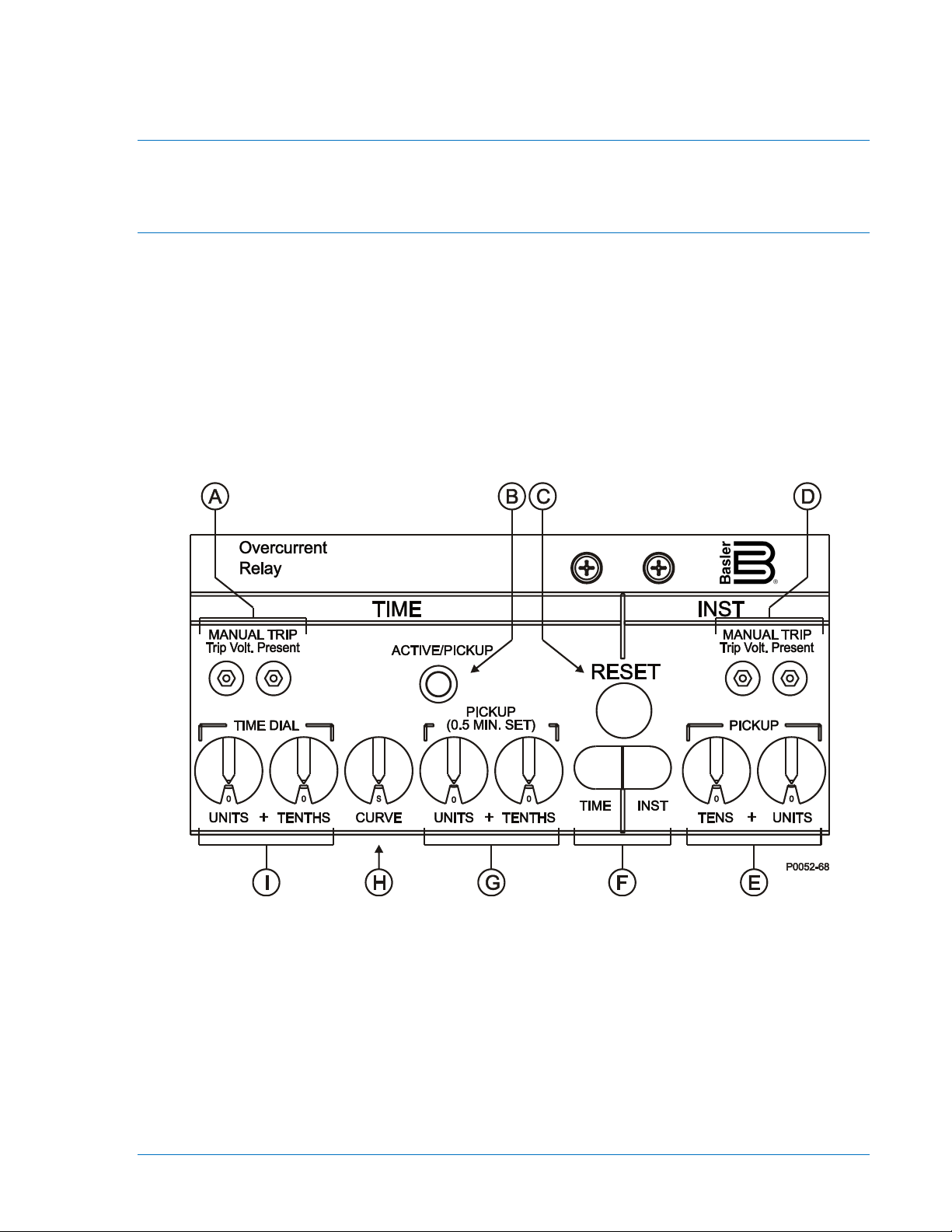
Front panel controls and indicators are illustrated in Figure 2-1 and described in Table 2-1. The locators
and descriptions of Table 2-1 correspond to the locators shown in Figure 2-1.
Figure 2-1. Front Panel Controls and Indicators
9252000894 Rev H BE1-50/51B-230/-234/-239 Controls and Indicators 2-1
Page 22

Table 2-1. Front Panel Controls and Indicators
Locator
Description
A
Time Overcurrent Manual Trip Jacks. These jacks are used to manually trip a breaker
terminated with two standard 0.08 inch diameter phone-tip plugs, into the two jacks.
B
Active/Pickup Indicator. This bicolor LED indicates the level of current sensed by the relay.
on 5A units or 0.1 A pickup setting on 1A units.
C
Target Reset Button. This button is pressed to reset the two, gravity-latched target
indicators (locator F).
E
Instantaneous Overcurrent A Pickup Selector Switches. These two rotary switches select
F
Target Indicators. Red target indicators latch when the corresponding set of trip contacts
indicators are reset by pressing the target reset button (locator C).
G
Time Overcurrent Pickup Selector Switches. These two rotary switches select the time
while the relay is in service may cause the relay to trip.
H
Curve Selector Switch. This ten position rotary switch selects one of nine inverse timing
I
Time Overcurrent Time Dial Selector Switches. These two rotary switches select the
these switches corresponds to a time delay of 0.0 to 9.9 seconds.
controlled by the 51 trip output contacts. This is achieved by plugging a jumper wire,
A green LED indicates that the relay is active but not picked up. The LED changes to red
when the sensed current exceeds the time overcurrent pickup setting. The LED changes
from red to green when the sensed current decreases below 95% of the time overcurrent
pickup setting.
Note: A minimum of 0.5 A (5A units) or 0.1 A (1A units) is required to light the LED. The
LED may not turn green (active) before turning red (picked up) at the 0.5 A pickup setting
D Instantaneous Overcurrent Manual Trip Jacks. These jacks are used to manually trip a
breaker controlled by the 50-A trip output contacts. This is achieved by plugging a jumper
wire, terminated with two standard 0.08 inch diameter phone-tip plugs, into the two jacks.
These jacks do not activate the 50-B trip output contacts.
the instantaneous overcurrent A (50-A) pickup current setting in amperes (UNITS and
TENTHS on the BE1-50/51B-230/-239, COARSE and FINE on the BE1-50/51B-234).
Adjusting these selector switches while the relay is in service may cause the relay to trip.
NOTE
When testing time overcurrent functions, instantaneous pickup settings of 00
will affect the calibration of the time functions. Time pickup settings of 00 also
affect instantaneous functions.
closes and sufficient trip circuit current is detected. (The level of current that will trip each
target indicator is jumper-selectable. See Circuit Board Controls for more information.) The
Time target indicates the flow of current in the time overcurrent (51) trip circuit. The Inst
target indicates the flow of current in the instantaneous overcurrent A (50-A) trip circuit. No
target is provided for the instantaneous overcurrent B (50-B) trip circuit. Both target
overcurrent pickup current setting in amperes (UNITS and TENTHS on the BE1-50/51B230/-239, COARSE and FINE on the BE1-50/51B-234). Adjusting these selector switches
characteristics or one fixed time function. Refer to Appendix A, Characteristic Curves for
details about the timing characteristics of the BE1-50/51B-230/-239 and BE1-50/51B-234.
desired curve of the timing characteristic selected by the Curve Selector Switch (locator H).
When a fixed time characteristic is used (Curve Selector Switch setting of F), the setting of
2-2 BE1-50/51B-230/-234/-239 Controls and Indicators 9252000894 Rev H
Page 23
Circuit Board Controls
Circuit board controls consist of two rotary selector switches, a four-position slide switch, and two
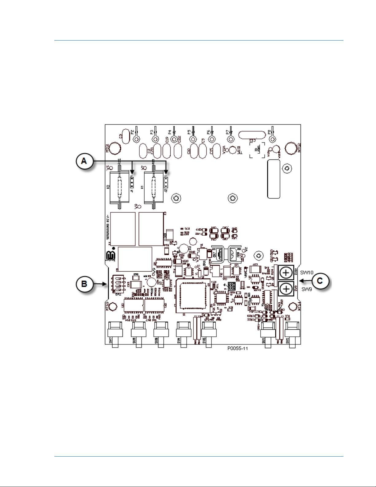
jumpers. Circuit board controls are illustrated in Figure 2-2 and described in Table 2-2. The locators and
descriptions of Table 2-2 correspond to the locators shown in Figure 2-2.
Figure 2-2. Circuit Board Controls
9252000894 Rev H BE1-50/51B-230/-234/-239 Controls and Indicators 2-3
Page 24

Table 2-2. Circuit Board Controls
Locator
Description
A
Target Operating Current Jumpers. Two user-adjustable jumpers control the range of trip
across pins 2 and 3 gives a minimum operating current of 80 to 200 mA.
B
Four Position Slide Switch. This switch assembly, designated SW3, has four independent
instantaneous reset characteristic.
C
Instantaneous Overcurrent B Pickup Selector Switches. These two screwdriver-adjusted,
circuit current required to operate the time overcurrent (51) and instantaneous overcurrent
A (50-A) target indicators. Jumper J1 sets the minimum current range for the 50-A target
indicator and J2 sets the minimum current range for the 51 target indicator. Two jumper
positions are possible: across pins 1 and 2 or across pins 2 and 3. Installing a jumper
across pins 1 and 2 gives a minimum operating current of 0.9 to 2.25 A. Installing a jumper
slide switches designated SW3-1, SW3-2, SW3-3, and SW3-4. Each switch functions as
follows:
SW3-1 selects the nominal system frequency. The OFF position selects 60 Hz operation
and the ON position selects 50 Hz operation.
SW3-2 provides an additional time delay for the instantaneous overcurrent A (50-A)
element. The ON position provides an additional delay of 100 milliseconds.
SW3-3 selects either GE IAC or ABB type characteristic curves. The ON position selects
the GE IAC type curves (listed in Table A-1) and the OFF position selects the ABB type
curves (listed in Table A-2).
SW3-4 selects either an instantaneous or integrating time reset characteristic. The ON
position selects an integrating reset characteristic and the OFF position selects an
rotary switches select the instantaneous overcurrent B (50-B) pickup current setting in
amperes.
The 50-B pickup switches are accessed on the top side of the draw-out assembly by
removing the draw-out assembly from the case. Figure 2-3 shows the 50-B pickup switches
as viewed at the right side of the draw-out assembly of the BE1-50/51B-230/-239. The BE150/51B-234 is shown in Figure 2-4.
BE1-50/51B-230/-239
The left-hand switch (SW9) is a 16-position switch that sets the units portion (#.#) of the 50B pickup setting in amperes. SW9 setting positions consist of 0 through 9 which correspond
to values of 0 to 9 amperes and A through F which correspond to values of 10 to 15
amperes. The right-hand switch (SW10) is a 10-position switch that sets the tenths portion
) of the 50-B pickup setting in amperes. SW10 setting positions consist of 0 through 9
(#.#
which correspond to values of 0.0 to 0.9 amperes.
The minimum allowable 50-B pickup setting is 1.0 Aac and the maximum allowable 50-B
pickup setting is 15.9 Aac. Adjusting the 50-B pickup selector switches while the relay is in
service may cause the relay to trip.
Example: SW9 position 2 and SW10 position 5 is a setting of 2.5 Aac.
BE1-50/51B-234
The total pickup setting is the sum of two settings. The first setting, SW9 has a range of 0.2
to 3.0 corresponding to switch position 1 through F. The second setting, SW10 has a range
of 0.02 to 0.18 corresponding to switch position 1 through 9.
The minimum allowable 50-B pickup setting is 0.2 Aac and the maximum allowable 50-B
pickup setting is 3.18 Aac. Adjusting the 50-B pickup selector switches while the relay is in
service may cause the relay to trip.
Example: SW9 position 2 and SW10 position 5 is a setting of 0.5 Aac.
2-4 BE1-50/51B-230/-234/-239 Controls and Indicators 9252000894 Rev H
Page 25

Figure 2-3. View of 50-B Pickup Selector Switches (BE1-50/51B-230/-239)
Figure 2-4. View of 50-B Pickup Selector Switches (BE1-50/51B-234)
9252000894 Rev H BE1-50/51B-230/-234/-239 Controls and Indicators 2-5
Page 26

2-6 BE1-50/51B-230/-234/-239 Controls and Indicators 9252000894 Rev H
Page 27

SECTION 3 • FUNCTIONAL DESCRIPTION
TABLE OF CONTENTS
SECTION 3 • FUNCTIONAL DESCRIPTION ........................................................................................... 3-1
Introduction ............................................................................................................................................ 3-1
Function Block Descriptions ................................................................................................................... 3-1
Current Sensing Input ........................................................................................................................ 3-1
Power CT and Power Supply ............................................................................................................. 3-1
Signal Conditioning ............................................................................................................................ 3-1
Microprocessor ................................................................................................................................... 3-1
Outputs ............................................................................................................................................... 3-2
Target Indicators ................................................................................................................................ 3-2
Figures
Figure 3-1. Function Block Diagram .......................................................................................................... 3-1
9252000894 Rev H BE1-50/51B-230/-234/-239 Functional Description i
Page 28

ii BE1-50/51B-230/-234/-239 Functional Description 9252000894 Rev H
Page 29

SECTION 3 • FUNCTIONAL DESCRIPTION
Introduction
This section illustrates and describes the functional capabilities of the BE1-50/51B-230, BE1-50/51B-234,
and BE1-50/51B-239 relays.
Function Block Descriptions
The function blocks of the BE1-50/51B-230, BE1-50/51B-234, and BE1-50/51B-239 relays are illustrated
in Figure 3-1 and described in the following paragraphs.
Figure 3-1. Function Block Diagram
Current Sensing Input
Single-phase ac current supplied by a system current transformer (CT) is applied to the BE1-50/51B-230,
BE1-50/51B-234, and BE1-50/51B-239 through terminals 5 and 6. Sensing current is applied to internal
power and signal CTs.
Power CT and Power Supply
The output of the power CT is supplied to the power supply which provides rectified and filtered operating
power for all relay circuitry. A precision 5 Vdc output of the power supply serves as a reference for
automatic calibration.
Signal Conditioning
Current from the signal CT is rectified and applied to three independent sets of scaling resistors controlled
by the Time Overcurrent (51), Instantaneous Overcurrent A (50-A), and Instantaneous Overcurrent B (50B) pickup switches. The analog-to-digital converter receives the analog voltage developed across the
scaling resistors and converts it into a digital signal that is supplied to the microprocessor.
Microprocessor
The microprocessor performs program operations based on the sensed current, switch settings, and the
internal software program.
When sufficient current is sensed by the relay, the microprocessor is active and executing code, and the
Active/Pickup LED is green. When the sensed current decreases below the operating threshold,
microprocessor operation is interrupted and the Active/Pickup LED turns off. A watchdog circuit resets the
microprocessor program when code execution is interrupted.
Power-off sensing circuits measure the voltage across a capacitor at power-down and power-up. These
circuits determine how long power has been removed based on the difference voltage and the circuit’s
9252000894 Rev H BE1-50/51B-230/-234/-239 Functional Description 3-1
Page 30

RC time constant. This provides information from the integrating reset function even when power has
been entirely removed.
The microprocessor defines the relay operating parameters based on inputs received from the Time
Overcurrent Time Dial Selector, Curve Selector, and four-position slide switch. The microprocessor
determines the level of sensed current by a digital signal supplied by the analog-to-digital converter.
Sensed current that exceeds the setting of the Time Overcurrent Pickup Selector switches causes the
Active/Pickup LED color to change from green to red and the 51 Trip output contacts to close in
accordance with the time characteristic equation. Sensed current exceeding the Instantaneous
Overcurrent A Pickup selector switch setting causes the 50-A Trip output contacts to close. Likewise,
sensed current exceeding the Instantaneous Overcurrent B Pickup selector switch setting causes the 50B Trip output contacts to close.
Outputs
Each protective element (time overcurrent (51), instantaneous overcurrent A (50-A), and instantaneous
overcurrent B (50-B)) is equipped with a set of normally-open contacts rated for tripping duty. A system
circuit breaker controlled by the 51 or 50-A output contacts can be manually tripped by connecting a
jumper across the Time Overcurrent Manual Trip jacks or the Instantaneous Overcurrent Manual Trip
jacks. (Manual trip jacks are not provided for the system circuit breaker controlled by the 50-B output
contacts.) Current flow in a trip circuit is indicated by operation of the corresponding target. The targets
will not operate without adequate relay operating power.
WARNING!
Trip circuit voltage is present at the front panel trip jacks. When shorting the
trip jacks, use insulated jumpers to avoid contact with these voltages.
Target Indicators
Gravity-latched, manually-reset, current-operated target indicators are provided for the time overcurrent
(51) trip output and the instantaneous overcurrent A (50-A) trip output. A target indicator is not provided
for the 50-B trip output. The level of trip circuit current required to operate each target is individually
controlled by a circuit board jumper. The minimum operating current range can be set for 80 to 200
milliamperes or 0.9 to 2.25 amperes. See Section 2, Controls and Indicators for jumper locations and
function assignments.
3-2 BE1-50/51B-230/-234/-239 Functional Description 9252000894 Rev H
Page 31

SECTION 4 • INSTALLATION
TABLE OF CONTENTS
SECTION 4 • INSTALLATION .................................................................................................................. 4-1
Introduction ............................................................................................................................................ 4-1
Factory Settings ..................................................................................................................................... 4-1
Installation (BE1-50/51B-230/-234 Only) ............................................................................................... 4-1
Mounting (BE1-50/51B-239 Only) .......................................................................................................... 4-2
Connections ........................................................................................................................................... 4-6
Application Coordination ........................................................................................................................ 4-7
Maintenance........................................................................................................................................... 4-8
Storage ................................................................................................................................................... 4-8
Figures
Figure 4-1. Outline Dimensions for S1 Case, Semi-Flush Mounting ......................................................... 4-2
Figure 4-2. Panel Drilling Diagram for S1 Case, Semi-Flush Mounting
Figure 4-3. Panel Drilling Diagram for S1 Case, Projection Mounting
Figure 4-4. Outline Dimensions for S1 Case, Projection Mounting
Figure 4-5. Typical AC Connections
Figure 4-6. Typical DC Connections
Figure 4-7. Coordination Timing Diagram
.................................................... 4-3
...................................................... 4-4
........................................................... 4-5
.......................................................................................................... 4-6
.......................................................................................................... 4-7
................................................................................................. 4-8
9252000894 Rev H BE1-50/51B-230/-234/-239 Installation i
Page 32

ii BE1-50/51B-230/-234/-239 Installation 9252000894 Rev H
Page 33

SECTION 4 • INSTALLATION
Introduction
BE1-50/51B-230 and BE1-50/51B-239 relays are direct replacements for General Electric IAC66K relays
with 5 Aac nominal current sensing. BE1-50/51B-234 relays are direct replacements for General Electric
IAC66K relays with 1 Aac nominal current sensing. The BE1-50/51B-230 and BE1-50/51B-234 relays are
supplied as draw-out assemblies that plug directly into existing cases for IAC66K relays. The draw-out
assembly is supplied with a relay cover and adapter plate for mounting the cover onto an existing IAC66K
case. The BE1-50/51B-239 relay is a draw-out assembly supplied with a case and cover. A connection
plug is supplied with all models.
If desired, proper relay operation may be confirmed by performing the test procedures listed in Section 5.
If the relay will not be installed immediately, store the relay in its original shipping carton in a moistureand dust-free environment.
Factory Settings
Factory settings for the internal switches of SW3 and jumper settings are as follows:
• SW3-1 — OFF (60 hertz operation).
• SW3-2 — OFF (0.0 additional fixed delay for the instantaneous element).
• SW3-3 — ON (GE IAC type characteristic curves).
• SW3-4 — ON (Integrating reset characteristics).
• J1 pins 2-3 — 50-A minimum target operating current of 80 to 200 mA
• J2 pins 1-2 — 51 minimum target operating current of 0.9 to 2.25 A
Installation (BE1-50/51B-230/-234 Only)
The relay must be configured with the appropriate settings before commissioning the relay in a specific
application. Changing the pickup settings while the relay is in service may cause tripping. Perform the
following steps to install the BE1-50/51B-230 or BE1-50/51B-234 relay in an existing GE IAC66K relay
case:
1. Remove the existing GE IAC66K relay from its case.
2. Using the four screws provided, attach the cover adapter to the existing case.
3. Insert the BE1-50/51B-230 or BE1-50/51B-234 into the case. Lock the draw-out assembly in place
with the cradle latches.
4. Install the new Basler Electric connection plug.
5. Install the cover supplied with the relay.
a. Align the interlocking bracket at the top of the cover with the mating receptacle at the top of the
cover adapter plate.
b. Secure the cover by tightening the captive knob at the bottom of the cover.
9252000894 Rev H BE1-50/51B-230/-234/-239 Installation 4-1
Page 34

Mounting (BE1-50/51B-239 Only)
D2750-29
Relay outline dimensions and panel drilling diagrams are shown in Figures 4-1 through 4-4. Dimensions
in parentheses are in millimeters.
Figure 4-1. Outline Dimensions for S1 Case, Semi-Flush Mounting
4-2 BE1-50/51B-230/-234/-239 Installation 9252000894 Rev H
Page 35

Figure 4-2. Panel Drilling Diagram for S1 Case, Semi-Flush Mounting
9252000894 Rev H BE1-50/51B-230/-234/-239 Installation 4-3
Page 36

Figure 4-3. Panel Drilling Diagram for S1 Case, Projection Mounting
4-4 BE1-50/51B-230/-234/-239 Installation 9252000894 Rev H
Page 37

When the relay is configured in a system with other devices, it is
4.03
4.03
.31
.75
6.19
(19.1)
(7.9)
(102.4)
(102.4)
(157.2)
10-32 SCREWS
MOUNTING PANEL
.25
(6.4)
A A
5/16-18 STUD
2 PLACES
TERMINAL EXTENSION (TYP.)
FOR DETAILED INSTRUCTIONS.
SEE THE TERMINAL PROJECTION
MOUNTING KIT SUPPLIED.
MOUNTING PANEL
(62.48)
2.195
(55.75)
(49.53)
1.95
2.40
DETAIL A-A
SHOWING THE ADDITION OF WASHERS
OVER THE BOSS TO TIGHTEN THE
RELAY AGAINST THE PANEL.
CASE
PANEL
12-17-99
D2750-25
NOTE: PROJECTION MOUNT USES WASHERS OVER THE BOSSES AS SHOWN IN THIS ILLUSTRATION.
Figure 4-4. Outline Dimensions for S1 Case, Projection Mounting
NOTE
Be sure that the relay is hard-wired to earth ground with no smaller than 12
AWG copper wire attached to the ground terminal on the rear of the unit case.
recommended to use a separate lead to the ground bus from each unit..
9252000894 Rev H BE1-50/51B-230/-234/-239 Installation 4-5
Page 38

Connections
Typical ac and dc connections are shown in Figures 4-5 and 4-6.
Figure 4-5. Typical AC Connections
4-6 BE1-50/51B-230/-234/-239 Installation 9252000894 Rev H
Page 39

CM
110
Figure 4-6. Typical DC Connections
Application Coordination
In a typical application coordination scheme, a BE1-50/51B-230, BE1-50/51B-234, or BE1-50/51B-239 is
used to provide primary protection for a radial distribution feeder. An electromechanical overcurrent relay
with extremely inverse timing provides protection for the transformer and bus. To improve coordination
with the electromechanical relay, the BE1-50/51B-230, BE1-50/51B-234, or BE1-50/51B-239 is
configured with the following settings:
• Integrating reset enabled (SW3-4 ON)
• Time characteristic curve E (extremely inverse) selected
• ABB type curves selected (SW3-3 OFF)
• Time dial set at 2.0
The feeder reclosing relay is set for two reclose attempts at 3 and 15 seconds after the initial trip. If a
permanent fault occurs (magnitude 10 times pickup), calculate the feeder breaker trip time for each of the
three operations. Refer to Appendix A for the characteristic curve constants and definition of the terms
used in the following time characteristic curve equations.
From the time characteristic curve equation:
T
=
0938.2
AD
=
T
N
−
27624.7
×
−
KBD
++
028.0)202758.0(
+×+
= 0.209 seconds
9252000894 Rev H BE1-50/51B-230/-234/-239 Installation 4-7
Page 40

From the reset characteristic curve equation:
1
M
seconds 15.5
10
27.75
2
−=
−
×
=
RD
=
T
R
2
−
M equals 0 if current goes to zero. A negative result indicates reset time.
Result: Full trip = 0.209 seconds and full reset = 15.5 seconds if current goes to zero.
In Figure 4-7:
= 0.209 seconds (relay was at reset)
T
A
= value<TA because rewind has not gone to zero
T
B
= value<TA because rewind has not gone to zero
T
C
Figure 4-7. Coordination Timing Diagram
Maintenance
BE1-50/51B-230, BE1-50/51B-234, and BE1-50/51B-239 relays require no preventative maintenance
other than periodic checking of relay connections to make sure that they are clean and tight. If the relay
fails to function properly, contact the Technical Sales Support department of Basler Electric.
Storage
This device contains long-life aluminum electrolytic capacitors. For devices that are not in service (spares
in storage), the life of these capacitors can be maximized by energizing the device for 30 minutes once
per year.
4-8 BE1-50/51B-230/-234/-239 Installation 9252000894 Rev H
Page 41

SECTION 5 • TESTING
TABLE OF CONTENTS
SECTION 5 • TESTING ............................................................................................................................ 5-1
Introduction ............................................................................................................................................ 5-1
Dielectric Test ........................................................................................................................................ 5-1
Test Procedures ..................................................................................................................................... 5-1
Model BE1-50/51B-230/-239 (Five Ampere Sensing Input)............................................................... 5-1
Time Overcurrent (51) Pickup ........................................................................................................ 5-1
Time Dial ......................................................................................................................................... 5-2
Integrating Reset ............................................................................................................................ 5-2
Instantaneous Overcurrent A (50-A) Pickup ................................................................................... 5-3
Instantaneous Overcurrent B (50-B) Pickup ................................................................................... 5-4
Manual Trip ..................................................................................................................................... 5-5
Target Indicators ............................................................................................................................. 5-6
Model BE1-50/51B-234 (One Ampere Sensing Input) ....................................................................... 5-7
Time Overcurrent (51) Pickup ........................................................................................................ 5-7
Time Dial ......................................................................................................................................... 5-7
Integrating Reset ............................................................................................................................ 5-7
Instantaneous Overcurrent A (50-A) Pickup ................................................................................... 5-8
Instantaneous Overcurrent B (50-B) Pickup ................................................................................... 5-9
Manual Trip ................................................................................................................................... 5-10
Target Indicators ........................................................................................................................... 5-11
Figures
Figure 5-1. 51 Pickup, Time Dial, and Integrating Reset Test Setup ........................................................ 5-3
Figure 5-2. 50-A Pickup Test Setup
Figure 5-3. 50-B Pickup Test Setup
Figure 5-4. Target Indicator Test Setup .................................................................................................... 5-6
Figure 5-5. 51 Pickup, Time Dial, and Integrating Reset Test Setup
Figure 5-6. 50-A Pickup Test Setup
Figure 5-7. 50-B Pickup Test Setup
Figure 5-8. Target Indicator Test Setup
.......................................................................................................... 5-4
.......................................................................................................... 5-5
........................................................ 5-8
.......................................................................................................... 5-9
........................................................................................................ 5-10
.................................................................................................. 5-11
9252000894 Rev H BE1-50/51B-230/-234/-239 Testing i
Page 42

ii BE1-50/51B-230/-234/-239 Testing 9252000894 Rev H
Page 43

SECTION 5 • TESTING
Observe all applicable electrostatic discharge (ESD) precautions when
Introduction
Proper relay operation may be confirmed by performing the test procedures in this section.
Dielectric Test
In accordance with IEC 255-5 and IEEE C37.90-2005, one-minute dielectric (high potential) tests may be
performed as follows:
All circuits to ground: 2,828 Vdc or 2,000 Vac
Input to output circuits: 2,828 Vdc or 2,000 Vac
Output contacts are surge protected.
Test Procedures
The following test procedures verify operation of the BE1-50/51B-230, BE1-50/51B-234, and BE150/51B-239 relays. The test setups illustrated in Figures 5-1 through 5-8 are intended primarily as an
illustration of the principles involved. Other test equipment known to be capable of testing with the stated
and implied tolerances (including equipment designed specifically for testing protective relays) may be
used.
The minimum test equipment requirements are:
• Current source with a range of 0 to 20 Aac (sensing input current)
• AC or DC voltage source (target operation)
• Timer or counter
NOTES
To ensure proper timing during testing, remove the current from the relay for R
times D seconds. (Refer to Appendix A, Characteristic Curves for definitions of
R and D.
When testing TIME overcurrent functions, INST PICKUP settings of 00 will
affect the calibration of the TIME functions. TIME PICKUP settings of 00 also
affect INST functions.
handling the relay assembly.
Model BE1-50/51B-230/-239 (Five Ampere Sensing Input)
Time Overcurrent (51) Pickup
1. Connect and configure the relay for 51 pickup testing:
a. Connect the test setup shown in Figure 5-1.
b. Set circuit board switch SW3 as follows:
SW3-1 = ON for 50 Hz operation or OFF for 60 Hz operation
SW3-2 = OFF (no additional time delay for the 50-A element)
SW3-3 = ON (GE IAC type characteristic curves)
SW3-4 = ON (integrating reset characteristic)
c. Set the TIME DIAL to 0.0.
d. Set CURVE to S.
e. Set TIME PICKUP to 0.5.
f. Set INST PICKUP (50-A) to 90.
g. Set INST PICKUP (50-B) (accessed at the top side of the assembly) to F0 (15.0 Aac).
9252000894 Rev H BE1-50/51B-230/-234/-239 Testing 5-1
Page 44

2. Apply and increase current to terminals 5 and 6 until the Active/Pickup LED turns red. The applied
current should be no greater than 0.55 Aac.
3. Decrease the applied current until the Active/Pickup LED changes from red to green and then off.
4. Set TIME PICKUP to 2.2.
5. Slowly increase current to terminals 5 and 6 until the Active/Pickup LED turns red. The applied
current should be between 2.131 and 2.269 Aac.
6. Reduce the applied current to zero.
Time Dial
1. Connect and configure the relay for time dial testing:
a. Connect the test setup shown in Figure 5-1.
b. Set circuit board switch SW3 as follows:
SW3-1 = ON for 50 Hz operation or OFF for 60 Hz operation
SW3-2 = OFF (no additional time delay for the 50-A element)
SW3-3 = ON (GE IAC type characteristic curves)
SW3-4 = ON (integrating reset characteristic)
c. Set TIME DIAL to 4.5.
d. Set CURVE to S.
e. Set TIME PICKUP to 1.0.
f. Set INST PICKUP (50-A) to 90.
g. Set INST PICKUP (50-B) (accessed at the top side of the assembly) to F0 (15.0 Aac).
2. Prepare to apply 1.5 Aac to terminals 5 and 6 and record the elapsed time from when current is
applied until the 51 output contacts close.
3. Apply the current (step from 0 to 1.5 Aac) and record the elapsed time. The elapsed time should be
between 0.345 and 0.424 seconds. (This tolerance is greater than ±2% because it is the
accumulation of both pickup and timing tolerances.)
4. Remove the input current.
Integrating Reset
1. Connect and configure the relay for integrating reset testing.
a. Connect the test setup shown in Figure 5-1.
b. Set circuit board switch SW3 as follows:
SW3-1 = ON for 50 Hz operation or OFF for 60 Hz operation
SW3-2 = OFF (no additional time delay for the 50-A element)
SW3-3 = ON (GE IAC type characteristic curves)
SW3-4 = ON (integrating reset characteristic)
c. Set TIME DIAL to 9.9
d. Set CURVE to V.
e. Set TIME PICKUP to 1.0.
f. Set INST PICKUP (50-A) to 90.
g. Set INST PICKUP (50-B) (accessed at the top side of the assembly) to F0 (15.0 Aac).
2. Apply 4.0 Aac to terminals 5 and 6. After the unit trips, remove the applied current for 29 ±0.25
seconds, then reapply the current (4.0 Aac). Note the elapsed time from the reapplication of current to
the second trip. The elapsed time should be 2.08 ±0.4 seconds.
5-2 BE1-50/51B-230/-234/-239 Testing 9252000894 Rev H
Page 45

Figure 5-1. 51 Pickup, Time Dial, and Integrating Reset Test Setup
Instantaneous Overcurrent A (50-A) Pickup
1. Connect and configure the relay for 50-A pickup testing:
a. Connect the test setup shown in Figure 5-2.
b. Set circuit board switch SW3 as follows:
SW3-1 = ON for 50 Hz operation or OFF for 60 Hz operation
SW3-2 = OFF (no additional time delay for the 50-A element)
SW3-3 = ON (GE IAC type characteristic curves)
SW3-4 = ON (integrating reset characteristic)
c. Set TIME DIAL to 0.0.
d. Set CURVE to S.
e. Set TIME PICKUP to 15.0.
f. Set INST PICKUP (50-A) to 02.
g. Set INST PICKUP (50-B) (accessed at the top side of the assembly) to F0 (15.0 Aac).
2. Apply and slowly increase current to terminals 5 and 6 until the 50-A output contacts close. The
applied current should be between 1.935 and 2.065 Aac.
3. Decrease the applied current until the 50-A output contacts open.
4. Set INST PICKUP (50-A) to 08.
5. Slowly increase the current applied to terminals 5 and 6 until the 50-A output contacts close. The
applied current should be between 7.815 and 8.185 Aac.
6. Reduce the applied current to zero.
9252000894 Rev H BE1-50/51B-230/-234/-239 Testing 5-3
Page 46

Figure 5-2. 50-A Pickup Test Setup
Instantaneous Overcurrent B (50-B) Pickup
1. Connect and configure the relay for 50-B pickup testing:
a. Connect the test setup shown in Figure 5-3.
b. Set circuit board switch SW3 as follows:
SW3-1 = ON for 50 Hz operation or OFF for 60 Hz operation
SW3-2 = OFF (no additional time delay for the 50-A element)
SW3-3 = ON (GE IAC type characteristic curves)
SW3-4 = ON (integrating reset characteristic)
c. Set TIME DIAL to 0.0.
d. Set CURVE to S.
e. Set TIME PICKUP to 15.0.
f. Set INST PICKUP (50-A) to 90.
g. Set INST PICKUP (50-B) (accessed at the top side of the assembly) to 20 (2.0 Aac).
2. Apply and slowly increase current to terminals 5 and 6 until the 50-B output contacts close. The
applied current should be between 1.935 and 2.065 Aac.
3. Decrease the applied current until the 50-B output contacts open.
4. Set INST PICKUP (50-B) to 80 (8.0 Aac).
5. Slowly increase the current applied to terminals 5 and 6 until the 50-B output contacts close. The
applied current should be between 7.815 and 8.185 Aac.
6. Reduce the applied current to zero.
5-4 BE1-50/51B-230/-234/-239 Testing 9252000894 Rev H
Page 47

Figure 5-3. 50-B Pickup Test Setup
Manual Trip
1. Configure the relay for manual trip testing:
a. Connect the test setup as shown in Figure 5-1.
b. Set circuit board switch SW3 as follows:
SW3-1 = ON for 50 Hz operation or OFF for 60 Hz operation
SW3-2 = OFF (no additional time delay for the 50-A element)
SW3-3 = ON (GE IAC type characteristic curves)
SW3-4 = ON (integrating reset characteristic)
c. Set TIME DIAL to 0.0
d. Set CURVE to S.
e. Set TIME PICKUP to 1.0.
f. Set INST PICKUP (50-A) to 90.
g. Set INST PICKUP (50-B) (accessed at the top side of the assembly) to 20 (2.0 Aac).
2. Apply 0.9 Aac to terminals 5 and 6 (0.9 Aac provides relay operating power but is below the pickup
threshold.)
3. Connect a jumper to the Time Overcurrent Manual Trip jacks. Verify that the stop input of the test set
timer recognizes a 51 contact closure.
4. Remove the jumper and the current applied at relay terminals 5 and 6.
5. Apply 0.9 Aac to terminals 5 and 6.
6. Connect a jumper to the Instantaneous Overcurrent Manual Trip jacks. Verify that the stop input of
the test set timer recognizes a 50-A contact closure
7. Remove the jumper and the current applied to relay terminals 5 and 6.
8. Reset targets.
WARNING!
Trip circuit voltage is present at the front panel trip jacks. When shorting the
trip jacks, use insulated jumpers to avoid contact with these voltages.
9252000894 Rev H BE1-50/51B-230/-234/-239 Testing 5-5
Page 48

Target Indicators
1. Connect and configure the relay for target indicator testing:
a. Connect the test setup shown in Figure 5-4.
b. Set circuit board switch SW3 as follows:
SW3-1 = ON for 50 Hz operation or OFF for 60 Hz operation
SW3-2 = OFF (no additional time delay for the 50-A element)
SW3-3 = ON (GE IAC type characteristic curves)
SW3-4 = ON (integrating reset characteristic)
c. Set TIME DIAL to 0.0.
d. Set CURVE to S.
e. Set TIME PICKUP to 1.0.
f. Set INST PICKUP (50-A) to 90.
g. Set INST PICKUP (50-B) (accessed at the top side of the assembly) to F0 (15.0 Aac).
The Target Operating Current Jumpers are located on the circuit board and identified as J1 and J2. J1
sets the minimum current range for the 50-A target and J2 sets the minimum current range for the 51
target. A jumper installed across pins 1 and 2 gives a minimum operating current of 0.9 to 2.25 A. A
jumper installed across pins 2 and 3 gives a minimum operating current of 80 to 200 mA.
2. Apply 2 Aac to terminals 5 and 6 to trip the 51 relay output.
3. Set voltage source to provide a target current determined by the target operating current jumpers.
4. Remove the target and sensing current and reset the target.
5. Set TIME PICKUP to 9.0.
6. Set INST PICKUP (50-A) to 01.
7. Apply 2 Aac to terminals 5 and 6 to trip the 50-A relay output.
8. Slowly increase the target current source and verify that the Instantaneous target operates at the
level of current determined by the Target Operating Current Jumpers.
9. Remove the target and sensing current and reset the targets.
Figure 5-4. Target Indicator Test Setup
5-6 BE1-50/51B-230/-234/-239 Testing 9252000894 Rev H
Page 49

Model BE1-50/51B-234 (One Ampere Sensing Input)
Time Overcurrent (51) Pickup
1. Connect and configure the relay for 51 pickup testing:
a. Connect the test setup shown in Figure 5-5.
b. Set circuit board switch SW3 as follows:
SW3-1 = ON for 50 Hz operation or OFF for 60 Hz operation
SW3-2 = OFF (no additional time delay for the 50-A element)
SW3-3 = ON (GE IAC type characteristic curves)
SW3-4 = ON (integrating reset characteristic)
c. Set the TIME DIAL to 0.0.
d. Set CURVE to S.
e. Set TIME PICKUP to 0.1.
f. Set INST PICKUP (50-A) to 18.0.
g. Set INST PICKUP (50-B) (accessed at the top side of the assembly) to F0 (3.0 Aac).
2. Apply and increase current to terminals 5 and 6 until the Active/Pickup LED turns red. The applied
current should be no greater than 0.11 Aac.
3. Decrease the applied current until the Active/Pickup LED changes from red to green and then off.
4. Set TIME PICKUP to 0.44.
5. Slowly increase current to terminals 5 and 6 until the Active/Pickup LED turns red. The applied
current should be between 0.426 and 0.454 Aac.
6. Reduce the applied current to zero.
Time Dial
1. Connect and configure the relay for time dial testing:
a. Connect the test setup shown in Figure 5-5.
b. Set circuit board switch SW3 as follows:
SW3-1 = ON for 50 Hz operation or OFF for 60 Hz operation
SW3-2 = OFF (no additional time delay for the 50-A element)
SW3-3 = ON (GE IAC type characteristic curves)
SW3-4 = ON (integrating reset characteristic)
c. Set TIME DIAL to 4.5.
d. Set CURVE to S.
e. Set TIME PICKUP to 0.2.
f. Set INST PICKUP (50-A) to 18.0.
g. Set INST PICKUP (50-B) (accessed at the top side of the assembly) to F0 (3.0 Aac).
2. Prepare to apply 0.3 Aac to terminals 5 and 6 and record the elapsed time from when current is
applied until the 51 output contacts close.
3. Apply the current (step from 0 to 0.3 Aac) and record the elapsed time. The elapsed time should be
between 0.345 and 0.424 seconds. (This tolerance is greater than ±2% because it is the
accumulation of both pickup and timing tolerances.)
4. Remove the input current.
Integrating Reset
1. Connect and configure the relay for integrating reset testing.
a. Connect the test setup shown in Figure 5-5.
b. Set circuit board switch SW3 as follows:
SW3-1 = ON for 50 Hz operation or OFF for 60 Hz operation
SW3-2 = OFF (no additional time delay for the 50-A element)
SW3-3 = ON (GE IAC type characteristic curves)
SW3-4 = ON (integrating reset characteristic)
9252000894 Rev H BE1-50/51B-230/-234/-239 Testing 5-7
Page 50

c. Set TIME DIAL to 9.9
d. Set CURVE to V.
e. Set TIME PICKUP to 0.2.
f. Set INST PICKUP (50-A) to 18.0.
g. Set INST PICKUP (50-B) (accessed at the top side of the assembly) to F0 (3.0 Aac).
2. Apply 0.8 Aac to terminals 5 and 6. After the unit trips, remove the applied current for 29 ±0.25
seconds, then reapply the current (0.8 Aac). Note the elapsed time from the reapplication of current to
the second trip. The elapsed time should be 2.08 ±0.4 seconds.
Figure 5-5. 51 Pickup, Time Dial, and Integrating Reset Test Setup
Instantaneous Overcurrent A (50-A) Pickup
1. Connect and configure the relay for 50-A pickup testing:
a. Connect the test setup shown in Figure 5-6.
b. Set circuit board switch SW3 as follows:
SW3-1 = ON for 50 Hz operation or OFF for 60 Hz operation
SW3-2 = OFF (no additional time delay for the 50-A element)
SW3-3 = ON (GE IAC type characteristic curves)
SW3-4 = ON (integrating reset characteristic)
c. Set TIME DIAL to 0.0.
d. Set CURVE to S.
e. Set TIME PICKUP to 3.18.
f. Set INST PICKUP (50-A) to 0.4.
g. Set INST PICKUP (50-B) (accessed at the top side of the assembly) to F0 (3.0 Aac).
2. Apply and slowly increase current to terminals 5 and 6 until the 50-A output contacts close. The
applied current should be between 0.387 and 0.413 Aac.
3. Decrease the applied current until the 50-A output contacts open.
4. Set INST PICKUP (50-A) to 1.6.
5-8 BE1-50/51B-230/-234/-239 Testing 9252000894 Rev H
Page 51

5. Slowly increase the current applied to terminals 5 and 6 until the 50-A output contacts close. The
applied current should be between 1.563 and 1.637 Aac.
6. Reduce the applied current to zero.
Figure 5-6. 50-A Pickup Test Setup
Instantaneous Overcurrent B (50-B) Pickup
1. Connect and configure the relay for 50-B pickup testing:
a. Connect the test setup shown in Figure 5-7.
b. Set circuit board switch SW3 as follows:
SW3-1 = ON for 50 Hz operation or OFF for 60 Hz operation
SW3-2 = OFF (no additional time delay for the 50-A element)
SW3-3 = ON (GE IAC type characteristic curves)
SW3-4 = ON (integrating reset characteristic)
c. Set TIME DIAL to 0.0.
d. Set CURVE to S.
e. Set TIME PICKUP to 3.18.
f. Set INST PICKUP (50-A) to 18.0.
g. Set INST PICKUP (50-B) (accessed at the top side of the assembly) to 20 (0.4 Aac).
2. Apply and slowly increase current to terminals 5 and 6 until the 50-B output contacts close. The
applied current should be between 0.387 and 0.413 Aac.
3. Decrease the applied current until the 50-B output contacts open.
4. Set INST PICKUP (50-B) to 80 (1.6 Aac).
5. Slowly increase the current applied to terminals 5 and 6 until the 50-B output contacts close. The
applied current should be between 1.563 and 1.637 Aac.
6. Reduce the applied current to zero.
9252000894 Rev H BE1-50/51B-230/-234/-239 Testing 5-9
Page 52

Figure 5-7. 50-B Pickup Test Setup
Manual Trip
1. Configure the relay for manual trip testing:
a. Connect the test setup as shown in Figure 5-5.
b. Set circuit board switch SW3 as follows:
SW3-1 = ON for 50 Hz operation or OFF for 60 Hz operation
SW3-2 = OFF (no additional time delay for the 50-A element)
SW3-3 = ON (GE IAC type characteristic curves)
SW3-4 = ON (integrating reset characteristic)
c. Set TIME DIAL to 0.0
d. Set CURVE to S.
e. Set TIME PICKUP to 0.2.
f. Set INST PICKUP (50-A) to 18.0.
g. Set INST PICKUP (50-B) (accessed at the top side of the assembly) at 20 (0.4 Aac).
2. Apply 0.18 Aac to terminals 5 and 6 (0.18 Aac provides relay operating power but is below the pickup
threshold.)
3. Connect a jumper to the Time Overcurrent Manual Trip jacks. Verify that the stop input of the test set
timer recognizes a 51 contact closure.
4. Remove the jumper and the current applied at relay terminals 5 and 6.
5. Apply 0.18 Aac to terminals 5 and 6.
6. Connect a jumper to the Instantaneous Overcurrent Manual Trip jacks. Verify that the stop input of
the test set timer recognizes a 50-A contact closure
7. Remove the jumper and the current applied to relay terminals 5 and 6.
8. Reset targets.
WARNING!
Trip circuit voltage is present at the front panel trip jacks. When shorting the
trip jacks, use insulated jumpers to avoid contact with these voltages.
5-10 BE1-50/51B-230/-234/-239 Testing 9252000894 Rev H
Page 53

Target Indicators
1. Connect and configure the relay for target indicator testing:
a. Connect the test setup shown in Figure 5-8.
b. Set circuit board switch SW3 as follows:
SW3-1 = ON for 50 Hz operation or OFF for 60 Hz operation
SW3-2 = OFF (no additional time delay for the 50-A element)
SW3-3 = ON (GE IAC type characteristic curves)
SW3-4 = ON (integrating reset characteristic)
c. Set TIME DIAL to 0.0.
d. Set CURVE to S.
e. Set TIME PICKUP to 0.2.
f. Set INST PICKUP (50-A) to 18.0.
g. Set INST PICKUP (50-B) (accessed at the top side of the assembly) to F0 (3.0 Aac).
The Target Operating Current Jumpers are located on the circuit board and identified as J1 and J2. J1
sets the minimum current range for the 50-A target and J2 sets the minimum current range for the 51
target. A jumper installed across pins 1 and 2 gives a minimum operating current of 0.9 to 2.25 A. A
jumper installed across pins 2 and 3 gives a minimum operating current of 80 to 200 mA.
2. Apply 0.4 Aac to terminals 5 and 6 to trip the 51 relay output.
3. Slowly increase the voltage source to provide target current and verify that the Time target operates
at the level of current determined by the Target Operating Current Jumpers.
4. Remove the target and sensing current and reset the target.
5. Set TIME PICKUP to 1.8.
6. Set INST PICKUP (50-A) to 0.2.
7. Apply 0.4 Aac to terminals 5 and 6 to trip the 50-A relay output.
8. Slowly increase the voltage source to provide target current and verify that the Instantaneous target
operates at the level of current determined by the Target Operating Current Jumpers.
9. Remove the target and sensing current and reset the targets.
Figure 5-8. Target Indicator Test Setup
9252000894 Rev H BE1-50/51B-230/-234/-239 Testing 5-11
Page 54

5-12 BE1-50/51B-230/-234/-239 Testing 9252000894 Rev H
Page 55

APPENDIX A • CHARACTERISTIC CURVES
TABLE OF CONTENTS
APPENDIX A • CHARACTERISTIC CURVES .......................................................................................... A-1
Introduction ............................................................................................................................................ A-1
Instantaneous Overcurrent Characteristics ........................................................................................... A-1
Timing ................................................................................................................................................. A-1
Pickup ................................................................................................................................................. A-1
Time Overcurrent Characteristics .......................................................................................................... A-2
Inverse Time Functions ...................................................................................................................... A-2
Characteristic Curve Groups .............................................................................................................. A-2
Timing Accuracy ............................................................................................................................... A-18
Fixed Time Characteristic................................................................................................................. A-18
Integrating Time Reset Characteristic ................................................................................................. A-18
Figures
Figure A-1. Instantaneous Characteristic Curves ...................................................................................... A-1
Figure A-2. Short Inverse (S) Time Characteristic Curve (SW3-3 Off, Similar to ABB CO-2)
Figure A-3. Long Inverse (L) Time Characteristic Curve (SW3-3 Off, Similar to ABB CO-5)
Figure A-4. Definite Time (D) Time Characteristic Curve (Similar to ABB CO-6)
Figure A-5. Moderately Inverse (M) Time Characteristic Curve (Similar to ABB CO-7)
Figure A-6. Inverse (I) Time Characteristic Curve (SW3-3 Off, Similar to ABB CO-8)
Figure A-7. Very Inverse (V) Time Characteristic Curve (SW3-3 Off, Similar to ABB CO-9)
Figure A-8. Extremely Inverse (E) Time Characteristic Curve (SW3-3 Off, Similar to ABB CO-11)
Figure A-9. BS142 Very Inverse (BS142-B) Time Characteristic Curve
Figure A-10. BS142 Extremely Inverse (BS142-C) Time Characteristic Curve
Figure A-11. Short Inverse (S2) Time Characteristic Curve (SW3-3 On, Similar to GE IAC 55)
Figure A-12. Long Inverse (L2) Time Characteristic Curve (SW3-3 On, Similar to GE IAC 66) ............. A-14
Figure A-13. Inverse (I2) Time Characteristic Curve (SW3-3 On, Similar to GE IAC 51)
Figure A-14. Very Inverse (V2) Time Characteristic Curve (SW3-3 On, Similar to GE IAC 53)
Figure A-15. Extremely Inverse (E2) Time Characteristic Curve (SW3-3 On, Similar to GE IAC 77)
Figure A-16. Integrating Reset Characteristic Curve
.................. A-4
................... A-5
..................................... A-6
........................... A-7
............................. A-8
.................... A-9
....... A-10
................................................. A-11
...................................... A-12
............ A-13
....................... A-15
............. A-16
.... A-17
............................................................................... A-18
Tables
Table A-1. Time Characteristic Curve Constants with Switch SW3-3 Open (Off) ..................................... A-2
Table A-2. Time Characteristic Curve Constants with Switch SW3-3 Closed (On)
9252000894 Rev H BE1-50/51B-230/-234/-239 Characteristic Curves i
.................................. A-3
Page 56

ii BE1-50/51B-230/-234/-239 Characteristic Curves 9252000894 Rev H
Page 57

APPENDIX A • CHARACTERISTIC CURVES
Introduction
This appendix describes and defines the instantaneous overcurrent, time overcurrent, and integrating
time reset characteristics of the BE1-50/51B-230, BE1-50/51B-234, and BE1-50/51B-239 relays.
Instantaneous Overcurrent Characteristics
Timing
The instantaneous characteristic curves of the BE1-50/51B-230, BE1-50/51B-234, and BE1-50/51B-239
relays are similar to standard electromechanical instantaneous units. However, the time to trip for
applications where the initial sensing current is less than 400 mA may be slightly longer. This may occur
on a very lightly loaded circuit or when the relay is providing ground protection and is connected to
measure neutral current. Figure A-1 shows the instantaneous characteristic curves for the maximum time
to trip.
Figure A-1. Instantaneous Characteristic Curves
The delay of the Instantaneous A (50-A) element can be set for no intentional delay (switch SW3-2 open)
or a fixed delay of 100 ms (SW3-2 closed). Figure 2-2 illustrates the location of SW3. The time delay of
the 50-B element is not switch-selectable and is fixed at no intentional delay.
Pickup
The instantaneous elements of the BE1-50/51B-230, BE1-50/51B-234, and BE1-50/51B-239 relays may
be set lower than the instantaneous element in IAC relays and still have the same reach. This is because
the BE1-50/51B-230, BE1-50/51B-234, and BE1-50/51B-239 instantaneous elements effectively eliminate
the fault current transient overreach components. When setting the BE1-50/51B-230, BE1-50/51B-234,
and BE1-50/51B-239 instantaneous elements, calculate the symmetrical value without any adder for
transient overreach.
9252000894 Rev H BE1-50/51B-230/-234/-239 Characteristic Curves A-1
Page 58

Time Overcurrent Characteristics
KBD
CM
AD
T
N
T
++
−
=
Curve
Type
BE A B C N K R
S
ABB CO-2
A-2
0.2663
0.03393
1.000
1.2969
0.028
0.500
L
ABB CO-5
A-3
5.6143
2.18592
1.000
1.0000
0.028
15.750
D
ABB CO-6
A-4
0.4794
0.21359
1.000
1.5625
0.028
0.875
M
ABB CO-7
A-5
0.3022
0.12840
1.000
0.5000
0.028
1.750
I
ABB CO-8
A-6
8.9341
0.17966
1.000
2.0938
0.028
9.000
V
ABB CO-9
A-7
5.4678
0.10814
1.000
2.0469
0.028
5.500
E
ABB CO-11
A-8
7.7624
0.02758
1.000
2.0938
0.028
7.750
B
BS142-B∗
A-9
1.4636
0.00000
1.000
1.0469
0.028
3.250
C
BS142-C∗
A-10
8.2506
0.00000
1.000
2.0469
0.028
8.000
F
None†
None
0.0000
1.00000
0.000
0.0000
0.000
1.000
Nine inverse time functions and one fixed (definite) time function can be selected at the front panel. Curve
types are identified by a letter designator. Available curve types are short inverse (S), long inverse (L),
definite time (D), moderately inverse (M), inverse (I), very inverse (V), extremely inverse (E), BS142
inverse, (B), and BS142 extremely inverse (C).
Inverse Time Functions
Characteristic curves for the inverse and definite time functions are defined by the following equation:
Where: T
= time to trip in seconds
T
D = time dial setting
M = multiple of pickup setting
A, B, C, N, K = constants for the particular curve
Characteristic Curve Groups
Either GE IAC or ABB characteristic curve groups are selected through switch SW3-3. (Refer to Figure 22 for the location of SW3.)
Characteristic Curve Constants
Tables A-1 and A-2 list the time characteristic curve constants used by the relay. Constants have been
selected to conform to the characteristics of electromechanical relays over a range of pickup multiples
from 1.3 to 40. Values of the constants are provided for use in PC relay setting applications. Timing
accuracy is ±1 cycle ±2% of time to trip.
Table A-1. Time Characteristic Curve Constants with Switch SW3-3 Open (Off)
Similar To
Figure
Number
Constants
∗ Curves B and C are defined in British Standard BS142 and IEC 255-4 (International Electrotechnical
Commission).
† Fixed time from 0.1 to 9.9 seconds.
A-2 BE1-50/51B-230/-234/-239 Characteristic Curves 9252000894 Rev H
Page 59

Table A-2. Time Characteristic Curve Constants with Switch SW3-3 Closed (On)
Type
BE A B C N K R
S
GE IAC 55
A-11
0.0286
0.0208
1.000
0.9844
0.028
0.0940
L
GE IAC 66
A-12
2.3955
0.00002
1.000
0.3125
0.028
7.8001
D
ABB CO-6
A-4
0.4797
0.21359
1.000
1.5625
0.028
0.8750
M
ABB CO-7
A-5
0.3022
0.12840
1.000
0.5000
0.028
1.7500
I
GE IAC 51
A-13
0.2747
0.1042
1.000
0.4375
0.028
0.8868
V
GE IAC 53
A-14
4.4309
0.0991
1.000
1.9531
0.028
5.8231
E
GE IAC 77
A-15
4.9883
0.0129
1.000
2.0469
0.028
4.7742
B
BS142-B∗
A-9
1.4636
0.00000
1.000
1.0469
0.028
3.2500
C
BS142-C∗
A-10
8.2506
0.00000
1.000
2.0469
0.028
8.0000
F
None†
None
0.0000
1.00000
0.000
0.0000
0.000
1.0000
Curve
Similar To
Figure
Number
Constants
∗ Curves B and C are defined in British Standard BS142 and IEC 255-4 (International Electrotechnical
Commission).
† Fixed time from 0.1 to 9.9 seconds.
9252000894 Rev H BE1-50/51B-230/-234/-239 Characteristic Curves A-3
Page 60

Characteristic Curves
Figures A-2 through A-15 illustrate the BE1-50/51B-230, BE1-50/51B-234, and BE1-50/51B-239 time
overcurrent characteristic curves.
Figure A-2. Short Inverse (S) Time Characteristic Curve (SW3-3 Off, Similar to ABB CO-2)
A-4 BE1-50/51B-230/-234/-239 Characteristic Curves 9252000894 Rev H
Page 61

Figure A-3. Long Inverse (L) Time Characteristic Curve (SW3-3 Off, Similar to ABB CO-5)
9252000894 Rev H BE1-50/51B-230/-234/-239 Characteristic Curves A-5
Page 62

Figure A-4. Definite Time (D) Time Characteristic Curve (Similar to ABB CO-6)
A-6 BE1-50/51B-230/-234/-239 Characteristic Curves 9252000894 Rev H
Page 63

Figure A-5. Moderately Inverse (M) Time Characteristic Curve (Similar to ABB CO-7)
9252000894 Rev H BE1-50/51B-230/-234/-239 Characteristic Curves A-7
Page 64

Figure A-6. Inverse (I) Time Characteristic Curve (SW3-3 Off, Similar to ABB CO-8)
A-8 BE1-50/51B-230/-234/-239 Characteristic Curves 9252000894 Rev H
Page 65

Figure A-7. Very Inverse (V) Time Characteristic Curve (SW3-3 Off, Similar to ABB CO-9)
9252000894 Rev H BE1-50/51B-230/-234/-239 Characteristic Curves A-9
Page 66

Figure A-8. Extremely Inverse (E) Time Characteristic Curve (SW3-3 Off, Similar to ABB CO-11)
A-10 BE1-50/51B-230/-234/-239 Characteristic Curves 9252000894 Rev H
Page 67

Figure A-9. BS142 Very Inverse (BS142-B) Time Characteristic Curve
9252000894 Rev H BE1-50/51B-230/-234/-239 Characteristic Curves A-11
Page 68

Figure A-10. BS142 Extremely Inverse (BS142-C) Time Characteristic Curve
A-12 BE1-50/51B-230/-234/-239 Characteristic Curves 9252000894 Rev H
Page 69

Figure A-11. Short Inverse (S2) Time Characteristic Curve (SW3-3 On, Similar to GE IAC 55)
9252000894 Rev H BE1-50/51B-230/-234/-239 Characteristic Curves A-13
Page 70

Figure A-12. Long Inverse (L2) Time Characteristic Curve (SW3-3 On, Similar to GE IAC 66)
A-14 BE1-50/51B-230/-234/-239 Characteristic Curves 9252000894 Rev H
Page 71

Figure A-13. Inverse (I2) Time Characteristic Curve (SW3-3 On, Similar to GE IAC 51)
9252000894 Rev H BE1-50/51B-230/-234/-239 Characteristic Curves A-15
Page 72

Figure A-14. Very Inverse (V2) Time Characteristic Curve (SW3-3 On, Similar to GE IAC 53)
A-16 BE1-50/51B-230/-234/-239 Characteristic Curves 9252000894 Rev H
Page 73

Figure A-15. Extremely Inverse (E2) Time Characteristic Curve (SW3-3 On, Similar to GE IAC 77)
9252000894 Rev H BE1-50/51B-230/-234/-239 Characteristic Curves A-17
Page 74

Timing Accuracy
1
2
−
=
M
RD
T
R
Trip to TimeKBD
CM
AD
T
N
T
=++
−
=
Reset to Time
M
RD
T
R
=
−=1
2
Timing accuracy is the sum of ±1 cycle, ±2%. This accuracy applies to the range of 1.3 to 40 times tap
and is for a given measured multiple of tap. Measurement accuracy of the multiple of tap is the sum of
±2%, ±25 mA for the BE1-50/51B-230 and ±2%, ±5 mA for the BE1-50/51B-234.
Fixed Time Characteristic
The fixed time characteristic corresponds to the time dial setting and provides delays of 0.0 to 9.9
seconds. The time setting is constant over a range of pickup multiples from 1.0 to 40. Accuracy is ±1
cycle, ±2% of the time to trip for time dial settings of 0.1 and greater.
Integrating Time Reset Characteristic
The relay can be user-configured for integrating or instantaneous type reset.
Integrating reset simulates the disk reset of electromechanical relays and begins when the current
decreases below 95% of pickup. BE1-50/51B-230 and BE1-50/51B-234 relays provide the integrating
reset function even when input current decreases to zero.
Integrating reset characteristics are defined by the following equation and are illustrated in Figure A-16.
See Table A-1 and A-2 for the equation constants.
Where: T
R = constant for the particular curve
D = time dial setting
M = current in multiples of pickup setting during reset
Time characteristic curve equation:
Where: D = time dial setting
M = multiple of pickup setting
Reset characteristic curve equation:
= time to reset in seconds
R
Figure A-16. Integrating Reset Characteristic Curve
Instantaneous Reset
Reset occurs within 16 ms of when the current decreases to 95% of the pickup level.
A-18 BE1-50/51B-230/-234/-239 Characteristic Curves 9252000894 Rev H
Page 75

Page 76

®
12570 State Route 143
Highland IL 62249-1074 USA
www.basler.com, info@basler.com
Phone +1 618.654.2341 Fax +1 618.654.2351
 Loading...