


 Loading...
BeoSound 5
Type 2900
BeoMaster 5
Type 1753, 1754, 1755
Service Manual
English
German, French, Italian, Spanish, Danish, Dutch, Japanese, Korean and Simplified Chinese versions are available in the Retail System
This Service Manual must be returned with the defective parts/back-up suitcase !
CONTENTS |
|
Survey of modules ......................................................................................... |
1.1 |
How to service ............................................................................................... |
1.2 |
ServiceTool .................................................................................................... |
1.4 |
Service mode ................................................................................................. |
2.1 |
Fault flow chart ............................................................................................. |
3.1 |
ServiceTool for adjustments ........................................................................... |
4.1 |
Adjustments .................................................................................................. |
4.7 |
Final check after repair ................................................................................. |
4.9 |
Replacement of modules – BeoSound 5 ......................................................... |
5.1 |
Replacement of modules – BeoMaster 5 ...................................................... |
5.19 |
Specification guidelines for service use ........................................................... |
6.1 |
Block diagram – BeoSound 5 ......................................................................... |
7.1 |
Block diagrams – BeoMaster 5 ....................................................................... |
7.2 |
Wiring diagram ............................................................................................. |
7.5 |
Available parts ............................................................................................... |
8.1 |

Survey of modules 1.1
Survey of modules
BeoSound 5
BeoMaster 5
51 |
58 |
|
|
|
14 |
|
13 |
|
61 |
|
01 |
|
52 |
|
12 |
|
11 |
PCB01 Mainboard
PCB11 IR
PCB12 Navigator
PCB13 Input
PCB14 |
Volume (not for sale) |
PCB51 |
LCD |
PCB52 |
Keyboard (not for sale) |
PCB58 |
Standby |
PCB61 |
Backlight Inverter |
94
FAN |
01 |
RAM
04
51
PCB01 Motherboard
|
RAM |
PCB04 |
Power Supply |
PCB51 |
ML-PL |
PCB94 |
HDD |

1.2How to service
How to service
Strategy
The product is to be serviced in the customer’s home.
The repair involves replacement of the module(s). The replaced modules must be returned for repair at the Bang & Olufsen Module Repair department. Error codes as well as an adequate fault description must be returned with each replaced part. For this purpose, use the Module Repair form or the form in the Retail System under Exchange Module.
To help the Bang & Olufsen Module Repair department it is very important to answer the following questions:
1.Which products are in the setup?
2.Which software versions are used in these products?
3.How are the products linked together?
4.What happens in the actual situation?
Fault explanation and demonstration
Before troubleshooting is initiated, let the customer demonstrate the fault, if possible.
Preparations before service
Always remember to download the latest version of the Service Manual from BeoWise. Use also an updated version of ServiceTool MKII to update the BeoMaster 5 ServiceTool (placed on a USB pen drive).
Servicing
The BeoMaster 5 and BeoSound 5 must be serviced by qualified technical personnel only.
If it is not possible to determine the location of the fault or if replacing spare parts does not clear the fault, please contact your national Service Center for technical support.
Handling
Like any other electronic equipment, this product must be handled with care. Particularly the BeoMaster 5 which contains a HDD (Hard Disc Drive), must be handled carefully. Otherwise, there is a major risk of damaging the HDD.
Generally, there are 4 main items (described on the next page) which require great attention, when handling the product:
-Handling when the product is disassembled (ESD, lithium battery).
-Lithium battery.
-Cleaning.
-Transport and handling.
Replacement of modules
If it is necessary to replace modules in BeoSound 5 or BeoMaster 5, there are 3 modules which require an adjustment after replacement as the serial number has to be transferred into the new module. The modules are:
-PCB01, Mainboard (BeoSound 5)
-PCB01, Motherboard (BeoMaster 5)
-PCB94, HDD (serial number backup for BeoMaster 5 and BeoSound 5) Please refer to adjustments for further information.
How to service 1.3
Warnings
Static electricity, ESD
STATIC ELECTRICITY
MAY DESTROY THE
PRODUCT
ESD |
Static electricity may damage the product. In BeoSound 5/BeoMaster 5 there are integrated circuits which operate with 1.8 volt, and that makes the product extremely sensitive to static electrity.
Static-protective field service kit.
A static-protective field service kit must always be used when the product is disassembled or modules are handled.
Follow the instructions in this Service Manual and use the ESD-mat for both old and new modules.
Please note:
When mains voltage on the product is required, remove the connection between the product and the ESD-mat.
The chassis or modules must always be connected to the static-protective field service kit or placed in an ESD-proof bag.
Lithium battery
WARNING!
Short-circuit and overcharging of some types of lithium batteries may result in a violent explosion.
CAUTION!
Danger of explosion if battery is incorrectly replaced:
Replace only with the same or equivalent type.
Cleaning
Never use alcohol or other solvents to clean any part of the product!
Wipe dust off the surfaces using a dry, soft cloth or a micro fibre cloth. Remove grease stains or persistent dirt with a soft, lint-free, firmly wrung cloth, dipped in a solution of water containing only a few drops of mild detergent, such as washing-up liquid.
To retain the optimum performance of the screen, make sure that no streaks or traces are left on the screen.
Use white gloves to avoid smudging the front glass.
Transport and handling
When transportation is required, it is recomended to:
-Place BeoSound 5 in the original packing.
-Use product cover on BeoMaster 5 to prevent scratching the surface.
Recommended tools for service
B&O ServiceTool and a PC.
White gloves.
Shoe covers.
Soft lint-free cloth (micro fibre cloth) for cleaning.
Product cover for transportation.

1.4ServiceTool
ServiceTool
General
The BeoMaster 5 ServiceTool is required in several service situations, e.g. update of firmware after replacement of certain modules. It is important that the BeoMaster 5 ServiceTool (placed on a USB pen drive) always is updated to the latest version.
Please use an updated version of ServiceTool MKII remember to update the BeoMaster 5 ServiceTool.
The BeoMaster 5 ServiceTool is also used to restore the serial number in the following modules, if they are replaced:
-PCB01, Mainboard (BeoSound 5).
-PCB01, Motherboard (BeoMaster 5).
If it is not possible ‘restore’ the serial number from the one of the modules, e.g. if both the HDD and the Motherboard are damaged, a new pre-programmed PCB01, Motherboard can be ordered from Bang & Olufsen Retail System under Daily Use and Master Code.
Furthermore, the ServiceTool is necessary to flash update the firmware on the following modules, if they are replaced:
-PCB01, Mainboard (BeoSound 5).
-PCB51, ML-PL.
-PCB01 Motherboard (BIOS).
This update is important to ensure correct functions in the product and optimal performance for the customer.
Additional
Beside the mandatory elements mentioned above, the ServiceTool also contains the opportunity to perform the following services:
-Clone System drives/Clone entire HDD (clones the drives on a present HDD).
-Backup/Restore (to a new HDD).
-Reboot of the system.
Please refer to adjustment/ServiceTool for a fully detailed description of the features in the ServiceTool.

Service mode 2.1
Service mode
Service Menus ................................................................................. |
2.2 |
General ....................................................................................... |
2.2 |
Access to ‘Customer Configuration Menu’ .................................. |
2.2 |
Access to ‘Service Configuration Menu’ ....................................... |
2.3 |
How to exit ‘Configuration Menus’ ............................................. |
2.4 |
Survey of ‘Configuration Menus’ ................................................. |
2.4 |
Menu overview ........................................................................... |
2.4 |
Description af menu items ........................................................... |
2.5 |
MODE (BeoSound 5 only) ...................................................... |
2.5 |
SOUND (BeoSound 5 only) .................................................... |
2.5 |
SYSTEM INFO ........................................................................ |
2.5 |
SYSTEM SETTINGS ................................................................ |
2.6 |
MAINTENANCE ..................................................................... |
2.6 |
PRODUCT INFO ..................................................................... |
2.7 |
NETWORK INFO .................................................................... |
2.8 |
NETWORK SETTINGS ............................................................. |
2.8 |
ROLES ................................................................................... |
2.9 |
RECOVERY ............................................................................ |
2.9 |
Access to Service Menu ............................................................. |
2.10 |
How to exit Service Menu .......................................................... |
2.11 |
Survey of ‘Service Menu’ ........................................................... |
2.12 |
Description af menu items ......................................................... |
2.12 |
Survey of control function ........................................................... |
2.13 |
BeoSound 5 functionality .......................................................... |
2.13 |
Beo4 functionality ..................................................................... |
2.13 |
Beo5 functionality ..................................................................... |
2.13 |

2.2 Service mode
Service Menus
General
This section describes the accessibility of the following three service menus in BeoSound 5/BeoMaster 5:
-‘Customer Configuration Menu’
-‘Service Configuration Menu’
-SERVICE MENU
The service menus can be accessed on BeoSound 5 or from the tv connected to BeoMaster 5. Both scenarios are described.
Access to ‘Customer Configuration Menu’
BeoMaster 5
-Select PC in the LIST on Beo4 and press GO / select the configured soft button, eg. PC on the screen on Beo5 and press OK.
-Beo4, press MENU 9 / Beo5, press Menu + 9 (the ‘+’ enables numerical soft buttons) on the screen.
-Press RED GO on Beo4 / RED OK on Beo5 (‘Configuration Menu’ expands). The procedure is illutrated below:
|
|
|
|
|
|
Configuration |
|
|
|
|
|
|
|
|
GO |
. |
|
|
|
|
|
EXIT |
. |
|
|
|
System info |
|
GO |
. |
|
|
|
|
|
1 |
. |
|
Configuration |
|
System Settings |
|
2 |
. |
|
|
|
|
|
3 |
. |
|
|
|
Maintenance |
|
4 |
. |
|
System Info |
|
|
|
5 |
. |
|
|
|
Picture |
|
6 |
. |
|
System Settings |
|
|
|
7 |
. |
|
|
|
Product Info |
|
8 |
. |
|
Maintenance |
|
|
|
9 |
Configuration |
|
|
|
|
|
|
|
|
Network Info |
||
|
0 |
. |
|
Picture |
|
|
|
|
|
|
|
|
|
MENU |
9 (Beo4) |
RED GO (Beo4) |
|
|
||
Menu |
‘+’ 9 (Beo5) |
RED OK (Beo5) |
|
|
||
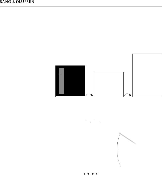
BeoSound 5
-Move the navigator arm  to MODE and use the wheel O to highlight SETTINGS.
-On BeoSound 5, press: 
 GO to activate ‘Customer Configuration Menu’ (the menu appears on left side of the screen, containing new sub menus).
MODE |
|
MODE |
|
|
|
SOUND |
|
COVERS |
|
|
|
|
N.MUSIC |
SYSTEM INFO |
|
ARTISTS |
|
|
|
|
|
|
|
|
N.RADIO |
SYSTEM SETTINGS |
|
ALBUMS |
|
|
|
|
SETTINGS |
|
VOLUME |
TITLES |
|
MAINTENANCE |
BALANCE |
|
|
||
|
|
|
BASS |
FAVOURITES |
|
PRODUCT INFO |
|
|
|
|
TREBLE |
QUEUE |
|
NETWORK INFO |
LOUDNESS |
|
|
|
Highlight SETTINGS and press 
 GO
GO
Service mode 2.3
Access to ‘Service Configuration Menu’
BeoMaster 5
-Select PC in the LIST on Beo4 and press GO / select the configured soft button, eg. PC on the screen on Beo5 and press OK.
-Press MENU 9 on Beo4 / press Menu + 9 (the ‘+’ enables numerical soft buttons) on the Beo5 screen.
-Press 0 0 GO on Beo4 / 0 0 OK on Beo5 (‘Configuration Menu’ expands).
The procedure is illutrated below:
GO .
EXIT .
GO .
1 |
. |
|
Configuration |
|
2 . |
|
|
||
3 . |
|
|
||
4 |
. |
|
System Info |
|
5 . |
|
|
||
6 |
. |
|
System Settings |
|
7 . |
|
|
||
8 |
. |
|
Maintenance |
|
.Configuration |
||||
9 |
|
|||
0 |
|
|
Picture |
|
|
|
|
|
|
MENU |
9 (Beo4) |
0 0 GO (Beo4) |
||
Menu |
‘+’ 9 (Beo5) |
0 0 OK (Beo5) |
||
BeoSound 5
Configuration
System info
System Settings
Maintenance
Picture
Product Info
Network Info
Network Settings
Roles
Recovery
- Move the navigator arm  to MODE and use the wheel O to highlight SETTINGS. - On BeoSound 5, press:


 GO to activate ‘Service Configuration Menu’
(the menu appears on left side of the screen, containing new sub menus).
MODE |
|
MODE |
|
|
|
|
|
|
|
SOUND |
|
COVERS |
|
|
|
|
|
SYSTEM INFO |
|
N.MUSIC |
|
|
|
ARTISTS |
|
SYSTEM SETTINGS |
|
|
|
|
|
N.RADIO |
|
|
VOLUME |
ALBUMS |
|
MAINTENANCE |
|
SETTINGS |
|
|
BALANCE |
TITLES |
|
PRODUCT INFO |
BASS |
|
|
|
|
|
|
NETWORK INFO |
|
|
|
|
TREBLE |
FAVOURITES |
|
NETWORK SETTINGS |
|
|
|
ROLES |
LOUDNESS |
|
|
|
|
QUEUE |
|
RECOVERY |
SPEAKER TYPE |
|
|
|
|
Highlight SETTINGS 


 GO
GO
Note!
The ‘Customer Configuration Menu‘ or ‘Service Configuration Menu’ must be activated from either BeoSound 5 or BeoMaster 5. It is not possible to activate the menus on both BeoSound 5 and BeoMaster 5 at the same time.

2.4Service mode
How to exit ‘Configuration Menus’
BeoMaster 5
-To exit ‘Configuration Menu’ on BeoMaster 5:
Press EXIT on Beo4 or BACK on Beo5 to return to BeoMaster 5 Main menu. (The number of times to press EXIT/BACK depends of the menu stage).
BeoSound 5
-To exit ‘Configuration Menu’ on BeoSound 5:
Move the navigator arm to MODE, use the wheel O to highlight N.MUSIC /
N.RADIO and press GO.
Survey of ‘Configuration Menus’
This chapter is a survey that describes the content of the ‘Customer Configuration Menu’ and the ‘Service Configuration Menu’ on BeoSound 5 and BeoMaster 5. The ‘Service Configuration Menu’ is the extended version of the ‘Customer Configuration Menu’, as opposed to the ‘Customer Configuration Menu’ contains all menu items.
Items marked with a ’*’ in the overview below is only available in the ‘Service Configuration Menu’.
Menu overview
BeoMaster 5 |
BeoSound 5 |
|
|
|
|
|
|
Configuration |
|
MODE |
|
System info |
|
SOUND |
|
|
|
|
|
System Settings |
|
SYSTEM INFO |
|
Maintenance |
|
SYSTEM SETTINGS |
|
Picture |
|
MAINTENANCE |
VOLUME |
|
|
|
|
Product Info |
|
|
|
* Network Info |
|
|
BALANCE |
|
|
|
|
* Network Settings |
|
PRODUCT INFO |
BASS |
|
|
||
* Roles |
|
*NETWORK INFO |
|
* Recovery |
|
*NETWORK SETTINGS |
TREBLE |
|
|
||
|
|
*ROLES |
LOUDNESS |
|
|
|
|
|
|
*RECOVERY |
SPEAKER TYPE |
|
|
|
|
Some menu items will only be available in BeoSound 5 and other only in BeoMaster 5. In the following description of the menu items, it will be mentioned whether the item is present in only BeoMaster 5 or BeoSound 5.
Service mode 2.5
Description af menu items
MODE (BeoSound 5 only)
This menu item provides the opportunity to choose one of the following options:
-N.MUSIC, opens the source N.Music and leaves ‘Configuration Menu’.
-N.RADIO, opens the source N.Radio and leaves ‘Configuration Menu’.
-SETTINGS, opens the basic SETTINGS menu and leaves ‘Configuration Menu’.
SOUND (BeoSound 5 only)
This menu item provides the opportunity to setup the settings for BeoSound 5.
- VOLUME, provides the opportunity to setup the default volume level. To enter, press  and a scale divided in steps from 0 to 90 appears on the screen.
- BALANCE, provides the opportunity to setup the default balance point. To enter, press  and a scale divided in steps from <9 to >9 appears on the screen.
-BASS, provides the opportunity to setup the default bass level. To enter press  and a scale divided in steps from -6 to 6 appears on the screen.
-TREBLE, provides the opportunity to setup the default treble level. To enter press  and a scale divided in steps from -6 to 6 appears on the screen.
-LOUDNESS, provides the opportunity to set loudness ON/OFF.
-SPEAKER TYPE, provides the opportunity to set whether a pair of BeoLab 5 is connected to BeoMaster 5 or not. This menu item is only visible when speakers are connected to one of the POWERLINK sockets on BeoMaster 5.
SYSTEM INFO
This menu item provides the opportunity to display information about the health of BeoMaster 5 and BeoSound 5. The information contains the following:
-BS5 CASE TEMP, reads out the temperature inside BeoSound 5 (in degrees Celsius).
-BM5 CASE TEMP, reads out the temperature inside BeoMaster 5 (in degrees Celsius).
-BM5 HDD TEMP, reads out the HDD temperature inside BeoMaster 5 (in degrees Celsius).
-BM5 UPTIME, reads out the time BeoMaster 5 has been connected to the mains.
-AVAILABLE STORAGE, reads out the free space left on the HDD in BeoMaster 5 (in gigabytes).

2.6Service mode
SYSTEM SETTINGS
BeoSound 5:
-LANGUAGE, provides the opportunity to setup the preferred language on BeoSound 5. The options are displayed on the respective languages and are: DANSK, DEUTSCH, ENGLISH, ESPANOL, FRANCAIS, ITALIANO, NEDERLANDS and SVENSKA (The setting does not have any impact to the language in ‘Customer Configuration Menu’ and ‘Service Configuration Menu’ as the only are available in english).
-TIME ZONE, this menu item provides the opportunity to setup the area where BeoSound 5 is installed. This setup is very important because it determines the time and thus the time for BeoMaster 5 to perform the automatic check for software updates. The options reaches from GMT-12:00 to GMT+13:00 (GMT stands for Greenwich Mean Time).
BeoMaster 5:
-Extended character set, provides the opportunity to enable the use of special characters (characters wich is not in common with the english character set), regarding to the chosen language.
-TIME ZONE, this item menu provides the opportunity to setup the area where BeoSound 5 is installed. This setup is very important because it determines the time and thus the time for BeoMaster 5 to perform the automatic check for software updates. The options reaches from GMT-12:00 to GMT+13:00 (GMT stands for Greenwich Mean Time).
MAINTENANCE
BeoSound 5/BeoMaster 5:
-CLEAN-UP*, this feature provides the opportunity to delete tracks or stations from the favourites list on BeoSound 5. The options are ON/OFF.
-UPDATE SOFTWARE, this feature provides the opportunity to perform on-demand software check/update. It is very important that BeoMaster 5 is not interrupted when the software update procedure is running.
The system is ready for use when the system has rebooted and the stby. LED lights red constantly.
-REBOOT, this feature reboots BeoMaster 5/BeoSound 5.
-SERVICE MENU**, this item menu accesses the service menu for BeoMaster 5, please refer to page 2.10 for further information.
*Only available on BeoSound 5
**Only available in ‘Service Configuration Menu’!

Service mode 2.7
PRODUCT INFO
PRODUCT INFO provides the opportunity to read-out information about software versions, type no., item no., serial no. etc. The items are described below.
BeoSound 5: |
|
|
BS5/BM5 APPLICATION |
Application software version |
|
BS5 MAIN FIRMWARE |
BeoSound 5 main firmware |
|
BS5 BOOT FIRMWARE |
BeoSound 5 boot firmware |
|
BS5 PCB |
BeoSound 5 PCB version |
|
BS5 BOM |
|
|
BS5 TYPE NO |
Type number for BeoSound 5 |
|
BS5 ITEM NO |
Item number for BeoSound 5 |
|
BS5 SERIAL NO |
Serial number for BeoSound 5 |
|
BM5 ML FIRMWARE |
BeoMaster 5 Master Link firmware |
|
BM5 ML PCB |
BeoMaster 5 |
Master Link PCB version |
BM5 MB BIOS |
BeoMaster 5 |
Motherboard BIOS |
BM5 SERIAL NO |
Serial number for BeoMaster 5 |
|
BM5 OS IMAGE |
BeoMaster 5 |
Operating System image |
BM5 OS UPDATE |
BeoMaster 5 |
Operating System update |
BeoMaster 5 (contains 2 sub-menus, one for BM5 and one for BS5):
Product info for BM5
BM5 Application |
BeoMaster 5 application software |
BM5 ML Firmware |
BeoMaster 5 Master Link firmware |
BM5 ML PCB |
BeoMaster 5 Master Link PCB version |
BM5 MB Bios |
BeoMaster 5 Motherboard BIOS |
BM5 Serial No |
Serial number for BeoMaster 5 |
BM5 OS Image |
BeoMaster 5 Operating System image |
BM5 OS Update |
BeoMaster 5 Operating System update |
Product Info for BS5 |
|
BS5 Main App |
BeoSound 5 main application firmware |
BS5 Main Firmware |
BeoSound 5 main firmware |
BS5 Boot Firmware |
BeoSound 5 boot firmware |
BS5 PCB |
BeoSound 5 PCB version |
BS5 BOM |
|
BS5 Type No |
Type number for BeoSound 5 |
BS5 Item No |
Item number for BeoSound 5 |
BS5 Serial No |
Serial number for BeoSound 5 |

2.8Service mode
NETWORK INFO
NETWORK INFO provides the opportunity to read-out network information. The elements are described below.
HOST NAME
Here the host name for BeoMaster 5 is read-out.
IP ADDRESS
Here the IP address for BeoMaster 5 is read-out.
MAC ADDRESS
Here the physical MAC address of the Ethernet adapter is read-out. If a wireless Ethernet adapter (WLAN) is connected, the MAC address for wireless adapter (WLAN) is shown, otherwise the read-out is for the wired network adapter (LAN).
CLIENTS CONNECTED
Here it is possible to see if a client PC is connected to BeoMaster 5, the options are ‘No clients connected’ or ‘1’.
INTERNET CONNECTION
This feature informs whether the network connection to the router/access point is OK or not. The options are YES/NO.
NETWORK SETTINGS
‘Network Settings’ provides the opportunity to set the ‘Client Password’. It is necessary to set the ‘Client Password’ in order to establish connection between BeoMaster 5 and the ‘Client PC’.
You can enter password data from both BeoSound 5 and BeoMaster 5.
Explanation for BeoSound 5:
O |
Changes/flicks through the characters. |
GO |
Accept the selected character. |
‘^’ |
Toggles between upper and lower case letters (placed in the character |
|
list). |
STORE |
Saves the created password (placed in the character list). |
Explanation for BeoMaster 5 (Beo4/Beo5): |
|
|
First press in the menu opens the character list. |
|
Second press and following, toggles between upper and lower case |
|
letters. |
|
Closes the character list. |
|
Moves the courser between the characters. |
GO/OK |
Saves the created password. |

Service mode 2.9
ROLES
This menu item provides the opportunity to define whether the BeoMaster 5/ BeoSound 5 is a AUDIO MASTER or not. If AUDIO MASTER is set to YES, it is possible to define which option the BeoMaster 5/BeoSound 5 is going to be in. If AUDIO MASTER is set to NO the ‘Option’ item is greyed out. The options are:
- |
AUDIO MASTER |
YES / NO |
- |
AM OPTIONS |
0 / 1 / 2 (greyed out if AUDIO MASTER is NO) |
RECOVERY |
|
|
|
If damages/faults for unexplainable reasons occur to the file system, and a total |
|
|
reinstallation is required, it is possible to perform a recovery of BeoMaster 5. The |
|
|
recovery function reinstalls all system files, with the only exception of the customer |
|
|
data such as music, pictures and preferred websites. |
|
|
The recovery process contains 2 steps which is illustrated below: |
|
- |
Step 1 of 2: Recovering system files. |
|
|
BeoMaster 5/BeoSound 5 reboots. |
|
- |
Step 2 of 2: Applying factory default settings. |
|
|
BeoMaster 5/BeoSound 5 reboots. |
|
- |
Then the recovery process is completed and the system is ready for use. |
|
|
The recovery process proceeds unattended when first executed. |
|
! |
It is very important that BeoMaster 5/BeoSound 5 is not interrupted during the |
|
|
process, to prevent major damages to the system. |
|
|
The recovery process is finished when the source menu is shown on the tv, or |
|
|
when the display on BeoSound 5 is off and the stby. LED lights red constantly. |
|
2.10Service mode
Access to Service Menu
BeoMaster 5
-Select PC in the LIST on Beo4 and press GO/select the configured soft button, eg. PC on the screen on Beo5 and press OK.
-Press MENU 9 on Beo4/press Menu + 9 (the ‘+’ enables numerical soft buttons) on the Beo5 screen.
-Press 0 0 GO on Beo4/0 0 OK on Beo 5 (‘Configuration Menu’ expands).
The procedure is illustrated below:
|
|
. |
|
|
|
GO |
|
|
|
|
EXIT |
. |
|
|
|
GO |
. |
|
|
|
1 |
. |
|
Configuration |
|
2 |
. |
|
|
|
3 |
. |
|
|
|
4 |
. |
|
System Info |
|
5 |
. |
|
|
|
6 |
. |
|
System Settings |
|
7 |
. |
|
|
|
8 |
. |
|
Maintenance |
|
.Configuration |
|
||
|
9 |
|
|
|
|
0 |
|
|
Picture |
|
|
|
|
|
MENU |
9 (Beo4) |
0 0 GO (Beo4) |
||
Menu |
‘+’ 9 (Beo5) |
0 0 OK (Beo5) |
||
- Move highlight text to ‘Service Menu’ and press GO/OK.
Configuration
System info
System Settings
Maintenance
Picture
Product Info
Network Info
Network Settings
Roles
Recovery
Move highlight text to ‘Maintenance’ and press GO/OK.
Maintenance
Update Software
Reboot
Service Menu
Now all running sources and processes related to BeoSound 5 or BeoMaster 5 shut down, and the SERVICE MENU appears on the screen.

Service mode 2.11
BeoSound 5
-Move the navigator arm  to MODE and use the wheel O to highlight
SETTINGS.
- On BeoSound 5, press: 


 GO to activate ‘Service Configuration Menu’ (the menu appears on left side of the screen, containing new sub menus).
-Move the navigator arm  to MAINTENANCE, use the wheel O to highlight
SERVICE MENU and press GO.
The procedure is illustrated below:
|
MODE |
|
MODE |
|
|
|
|
|
|
|
|
|
|
|
|
|
SOUND |
|
|
|
|
COVERS |
|
|
|
|
|
|
|
|
SYSTEM INFO |
|
|
|
|
N.MUSIC |
|
|
|
|
|
|
ARTISTS |
|
SYSTEM SETTINGS |
|
|
|
|
|
|
|
|
|
|
|
N.RADIO |
|
|
VOLUME |
|
|
|
ALBUMS |
|
MAINTENANCE |
|
|
|
|
|
|
|
|
||
|
SETTINGS |
|
|
BALANCE |
|
|
|
TITLES |
|
PRODUCT INFO |
BASS |
|
|
|
|
|
|
|
|
|
|
|
|
NETWORK INFO |
|
|
|
|
|
|
|
TREBLE |
|
|
|
FAVOURITES |
|
NETWORK SETTINGS |
|
|
|
|
|
|
ROLES |
LOUDNESS |
|
|
|
|
|
|
|
|
|
|
QUEUE |
|
RECOVERY |
|
SPEAKER TYPE |
|
|
|
|
|
|
|
|
- Highlight SETTINGS |
- Move the navigator arm |
to |
||||
|
GO |
MAINTENANCE, use the wheel O to |
||||
|
|
|
highlight SERVICE MENU and press GO. |
|||
Now all running sources and processes related to BeoSound 5 or BeoMaster 5 shut down, and the SERVICE MENU appears on the screen.
How to exit Service Menu
-To exit Service Menu on BeoSound 5/BeoMaster 5, double click the ‘Exit Service Menu’ icon on the desktop, and the product returns to its normal state.
2.12Service mode
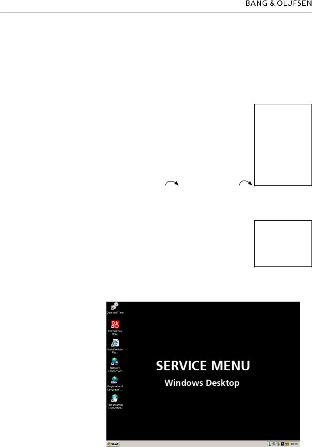
Survey of ‘Service Menu’
This chapter is a survey that describes the shortcuts of the icons in the ‘Service Menu’ on BeoSound 5 and BeoMaster 5. The purpose of these shortcuts is to give an easy access to the different features. The shortcuts are:
-‘Date and Time’
-‘Exit Service Menu’
-‘Install Adobe Flash’
-‘Network Connections’
-‘Regional and Language Options’
-‘Test Internet Connection’
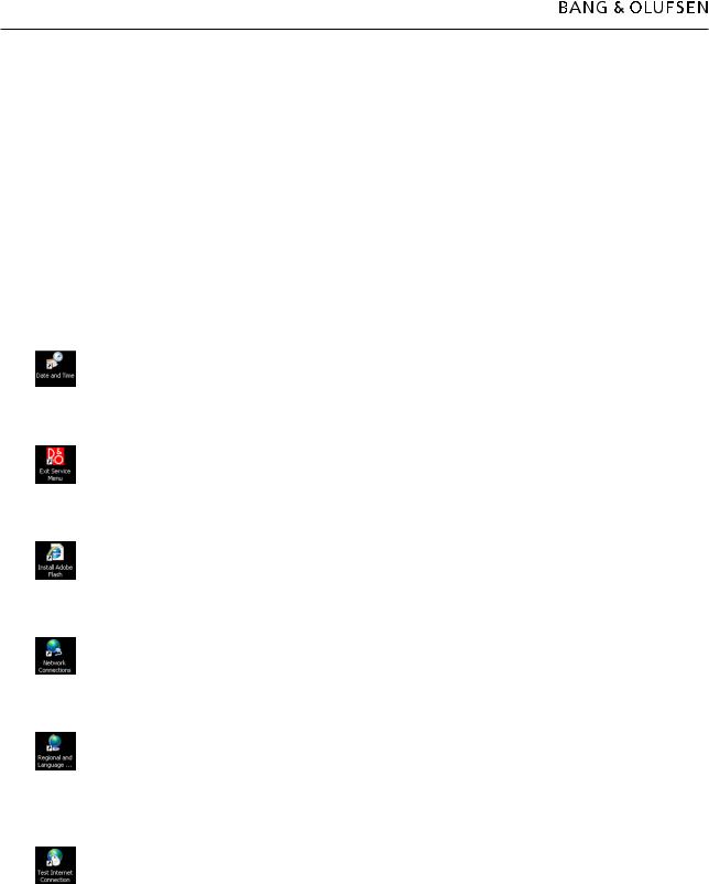
Description af menu items
‘Date and Time’
This icon is a shortcut to ‘Date and Time’ and provides the opportunity to manually set the date, time and time zone. This could be relevant if the auto update of date and time could not be performed.
‘Exit Service Menu’
This icon exits the ‘Service Menu’ and returns the product to its normal state.
‘Install Adobe Flash’
The shortcut ‘Install Adobe Flash’ is a link to install a ‘Flash Player’ which provides the opportunity to browse ‘Flash’ media files on BeoMaster 5 (WEB).
‘Network Connections’
The shortcut ‘Network Connections’ provides the opportunity to manually set up the settings for the network connection. This shows installations with a wireless network connection or a network without a ‘DHCP server’.
‘Regional and Language Options’
This icon is a shortcut to ‘Regional and Language Options’, and provides the opportunity to manually set up regional options and languages options (eg. text services and input languages). It might be necessary to perform this setup, if a router with special characters is installed in the network setup.
‘Test Internet Connection’
This icon is a shortcut to Bang & Olufsen’s homepage on the internet. The link provides the opportunity to check the internet connection from ‘Service Mode’. If the home page is shown, the internet connection is ok.

Service mode 2.13
Survey of control function
BeoSound 5 functionality
Selects/enters the high-lighted sub-menu.
Back to the previous menu, modified data is not saved.
GO Selects items.
Saves the modified data and leaves the sub-menu to the previous menu.
O Scrolls through menu items, radio stations, music files etc.
Moves the pointer on the screen according to the direction of the naviigation arm.
Beo4 functionality
MENU Bring up the menu overlay.
GO Selects the sub-menu where the cursor is located.
Accepts a menu, saving the values that have been entered.
Activates a function.
Moves the cursor bar up. Edits characters in the characters list.
Moves the cursor bar down. Edits characters in the characters list.
Selects a sub-menu in special cases.
 /
/  Modifies data.
STOP Back to the previous menu, modified data is not saved.
Digit
0 - 9 Modifies data.
Beo5 functionality
MENU Bring up the menu overlay.
OK, selects the sub-menu where the cursor is located.
Accepts a menu, saves the values that have been entered.
Activates a function.
Moves the cursor bar up. Edits characters in the characters list.
Moves the cursor bar down. Edits characters in the characters list.
Selects a sub-menu in special cases.
 /
/  Modifies data.
BACK Back to the previous menu, modified data is not saved.
Digit
0 - 9 Modifies data.

2.14
Fault flow chart 3.1
Fault flow chart
No function in BM5 ..................................................................... |
3.2 |
No red LED in BS5 ....................................................................... |
3.3 |
No function in BS5 ...................................................................... |
3.3 |
No operation of BS5 .................................................................... |
3.4 |
No ‘click sound’ (Stby. LED in BS5 OK) ......................................... |
3.4 |
No or incomplete boot sequence ................................................. |
3.5 |
Boot error (disk boot failure) ........................................................ |
3.5 |
No/faulty picture on BeoSound 5. (Stby. LED is OK) ...................... |
3.6 |
No display (no Bang & Olufsen text on DVI-D at startup) ............. |
3.7 |
No HDD activity (fan ok) .............................................................. |
3.7 |
No sound from BeoMaster 5 ....................................................... |
3.8 |
No N.Radio connection ................................................................ |
3.9 |
3.2Fault flow chart
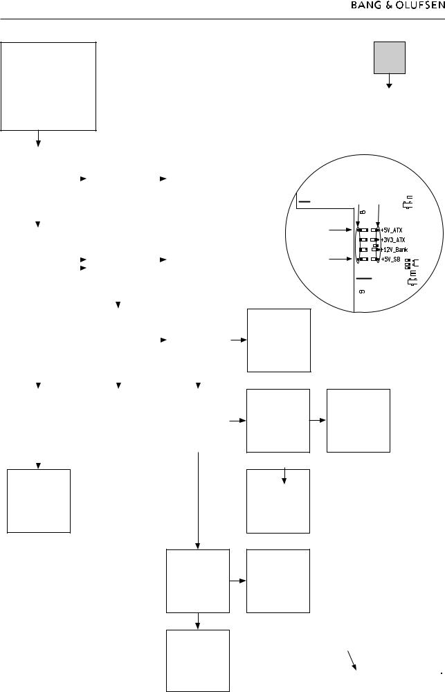
Fault symptom:
No function in BM5
Possible causes:
Defective PCB01,
Motherboard
Defective PCB4, SMPS
Defective PCB51, ML-PL
Defective 94, HDD
Confirm mains |
|
|
|
|
|
|
|
Poor or defective |
||
|
|
|
|
|
|
|
AC connection on |
|||
connection is ok by |
|
|
|
|
|
|
|
|||
|
|
|
Replace mains cable |
|
|
PCB04, Power |
||||
measuring on PCB4, |
|
|
|
|
|
|||||
|
|
|
|
|
|
|
Supply |
|||
P19, pin1-2 |
|
|
|
OK? |
|
|
||||
|
|
|
|
|
|
|
||||
|
|
|
|
|
|
|
|
|
||
OK? |
|
|
|
|
|
|
|
Replace PCB04, |
||
|
|
|
|
|
|
|
Power Supply |
|||
|
|
|
|
|
|
|
|
|
||
|
|
|
|
|
|
|
|
|
|
|
|
|
|
|
|
|
|
|
|
|
|
|
|
|
|
|
|
|
|
|
|
|
|
|
|
|
|
Disconnect W10 |
|
|
|
|
|
|
|
|
|
|
from PCB04, P18, |
|
|
|
|
|
Does the status LED |
|
|
|
and confirm |
|
|
Replace defective |
|||
shine red ? |
|
|
|
+12V_BUS on |
|
|
PCB04, Power |
|||
|
|
|
|
|
||||||
** |
|
|
|
PCB04, P18, pin 2-3 |
|
|
Supply |
|||
|
|
|
|
|
||||||
|
|
|
|
|
+5V_SB on PCB04, |
|
|
|
|
|
|
|
|
|
|
P18, pin 23. OK? |
|
|
|
|
|
|
|
|
|
|
|
|
|
|
|
|
|
|
|
|
|
|
|
|
|
|
|
|
|
|
|
|
|
|
|
|
|
|
|
|
|
|
|
Reconnect W10. |
|
|
|
|
|
|
|
|
|
|
On PCB51 confirm*: |
|
|
Confirm 0V on |
||
|
|
|
|
|
+3V3_ATX, |
|
|
|||
|
|
|
|
|
|
|
PCB51, P101 pin 9 |
|||
|
|
|
|
|
+5V_ATX, |
|
|
|||
|
|
|
|
|
|
|
|
|
||
|
|
|
|
|
+12V_Bank |
|
|
OK? |
||
|
|
|
|
|
|
|
|
|
||
|
|
|
|
|
OK? |
|
|
|
|
|
|
|
|
|
|
|
|
|
|
|
|
|
|
|
|
|
|
|
|
|
|
|
|
|
|
|
|
|
|
|
|
|
|
Push the POWER |
|
|
|
|
|
|
|
Disconnect W9 |
||
button on the rear |
|
|
|
|
|
|
|
from PCB94, HDD |
||
panel, and confirm |
|
|
|
Replace defective |
|
|
and W12 from |
|||
the power-up |
|
|
|
PCB01, |
|
|
PCB51, P150. |
|||
|
|
|
|
|
||||||
sequence |
|
|
|
Motherboard |
|
|
Confirm the before |
|||
|
|
|
|
|
|
|
|
|
mentioned voltages |
|
OK? |
|
|
|
|
|
|
|
again* OK? |
||
|
|
|
|
|
|
|
|
|
|
|
|
|
|
|
|
|
|
|
|
|
|
Done
Reconnect W9 to PCB94, HDD.
Confirm the before mentioned voltages again*
OK?
Fault in
BeoSound 5. Please refer to the next page.
 No
No
Yes
*Measuring points
PCB51
GND Voltage
+5V
+3.3V 

+12V 

+5V
Replace defective
PCB01,
Motherboard
Disconnect W5 from PCB51, P101. Confirm the before mentioned voltages again*
OK?
Replace defective PCB51, ML-PL
Replace defective
PCB01,
Motherboard
Replace defective
PCB94, HDD Power
Supply
** Status LED on BeoMaster 5
MASTER UNIT |
IR SPDIF |
M |
|
|
|

Fault flow chart 3.3
Fault symptom:
No red LED in BS5
No function in BS5
Possible causes:
Defective PCB01,
Mainboard
Defective PCB13, Input
Defective PCB61,
Backlight Inverter
Defective BM5
Confirm BM5 is |
|
|
Confirm |
|
|
Confirm |
|
|
|
||
powered on. |
|
|
+5V_SB_AUX |
|
|
+12V_BUS on |
|
|
|
||
Confirm |
|
|
+12V_AUX from |
|
|
PCB04, P18 pin 2-3, |
|
|
Follow the fault |
||
+5V_SB_AUX, |
|
|
BM5 power outlet |
|
|
+5V_SB on PCB04, |
|
|
flow chart on the |
||
|
|
|
|
|
|||||||
+12V_AUX |
|
|
(P150) |
|
|
P18 pin 23 |
|
|
previous page |
||
in the power cable* |
|
|
|
|
|
|
|
|
|
|
|
for BS5 OK? |
|
|
OK? |
|
|
OK? |
|
|
|
||
|
|
|
|
|
|
|
|
|
|
|
|
|
|
|
|
|
|
|
|
|
|
|
|
 No
No
Yes
|
|
|
|
|
|
|
|
|
|
|
|
|
|
|
|
|
|
|
|
|
Replace defective |
|
|
Replace defective |
|
|
|
|
|
|
|
||
|
|
|
|
W12, power cable |
|
|
|
|
|
|
|
|
|
|||
|
|
|
|
|
|
PCB51, ML-PL |
|
|
|
|
|
|
|
|||
|
|
|
|
for BS5 |
|
|
|
|
|
|
|
|
|
|||
|
|
|
|
|
|
|
|
|
|
|
|
|
|
|
||
|
|
|
|
|
|
|
|
|
|
|
|
|
|
|
|
|
|
|
|
|
|
|
|
|
|
|
|
|
|
|
|
|
|
|
|
|
|
|
|
|
|
|
|
|
|
|
|
|
|
|
Confirm |
|
|
|
|
|
|
|
|
|
|
|
|
|
|
|
|
+5V_AUX on |
|
|
|
|
|
|
|
|
|
|
|
|
|
|
|
|
PCB13, P4 pin 9, |
|
|
Replace defective |
|
|
|
|
|
|
|
|
|
|
|
||
+12V_AUX on |
|
|
|
|
|
|
|
|
|
|
|
|
|
|||
|
|
PCB13, Input |
|
|
|
|
|
|
|
|
|
|
|
|||
PCB13, P4 pin 5-8 |
|
|
|
|
|
|
|
|
|
|
|
|
|
|||
|
|
|
|
|
|
|
|
|
|
|
|
|
|
|
||
OK? |
|
|
|
|
|
|
|
|
|
|
|
|
|
|
|
|
|
|
|
|
|
|
|
|
|
|
|
|
|
|
|
|
|
|
|
|
|
|
|
|
|
|
|
|
|
|
|
|
|
|
|
|
|
|
|
|
|
|
|
|
|
|
|
|
|
|
|
Confirm |
|
|
Remove W23 from |
|
|
Remove W21 from |
|
|
Remove W20 from |
|
|
|
||||
|
|
PCB01, Mainboard. |
|
|
PCB01, Mainboard. |
|
|
PCB01, Mainboard. |
|
|
|
|||||
+3V3_SB on PCB01, |
|
|
|
|
|
|
|
|
Replace defective |
|||||||
|
|
Confirm: |
|
|
Confirm: |
|
|
Confirm: |
|
|
||||||
Mainboard, P10 |
|
|
|
|
|
|
|
|
PCB01, Mainboard |
|||||||
|
|
+3V3_SB on PCB01, |
|
|
+3V3_SB on PCB01, |
|
|
+3V3_SB on PCB01, |
|
|
||||||
pin 1 |
|
|
|
|
|
|
|
|
and reconnect |
|||||||
|
|
Mainboard, P10 |
|
|
Mainboard, P10 |
|
|
Mainboard, P10 |
|
|
||||||
|
|
|
|
|
|
|
|
|
|
W23, W21, W20 |
||||||
|
|
|
|
pin 1 |
|
|
pin 1 |
|
|
pin 1 |
|
|
||||
OK? |
|
|
|
|
|
|
|
|
|
|||||||
|
|
OK? |
|
|
OK? |
|
|
OK? |
|
|
|
|||||
|
|
|
|
|
|
|
|
|
|
|
||||||
|
|
|
|
|
|
|
|
|
|
|
|
|
|
|
|
|
|
|
|
|
|
|
|
|
|
|
|
|
|
|
|
|
|
|
|
|
|
|
|
|
|
|
|
|
|
|
|
|
|
|
|
|
|
|
Replace defective |
|
|
Replace defective |
|
|
Replace defective |
|
|
|
|||
Replace defective |
|
|
|
|
PCB14, Volume and |
|
|
PCB12, Navigator |
|
|
|
|||||
|
|
PCB58, Standby and |
|
|
|
|
|
|
|
|||||||
PCB01, Mainboard |
|
|
|
|
reconnect W23, |
|
|
and reconnect |
|
|
|
|||||
|
|
reconnect W23 |
|
|
|
|
|
|
|
|||||||
|
|
|
|
|
|
W21 |
|
|
W23, W21, W20 |
|
|
|
||||
|
|
|
|
|
|
|
|
|
|
|
|
|
||||
|
|
|
|
|
|
|
|
|
|
|
|
|
|
|
|
|
*BS5 power cable
1GND
25V_AUX
312V_AUX
4 IR
4 1
3 2
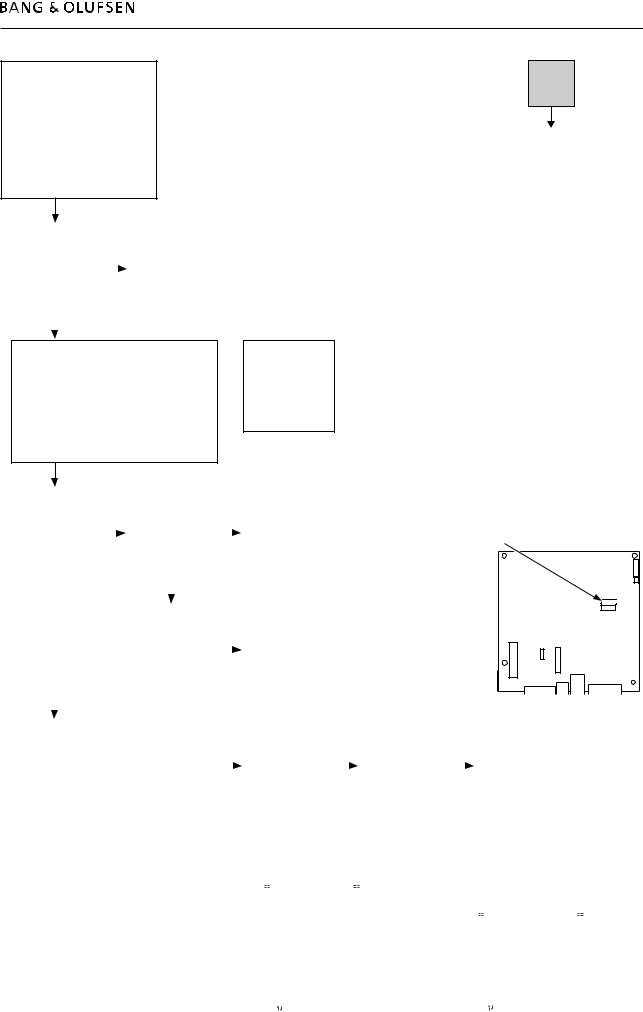
Survey of connector placement on PCB01
P6 |
P11 |
|
|
|
|
|
|
P2 |
P5 |
|
|
|
P8 |
P1 |
P4 |
|
P10 |
|
|
|
|
|
P7 |
P9 P3

3.4Fault flow chart
Fault symptom:
No operation of BS5
No ‘click sound’ (Stby. LED in
BS5 OK)
Possible causes, defective:
USB cable
PCB51, ML-PL
PCB01, Mainboard
PCB01, Motherboard
Restart |
|
|
|
|
BeoSound 5/ |
|
|
Replace USB cable |
|
BeoMaster 5 |
|
|
OK? |
|
|
|
|
||
|
|
|
|
|
OK? |
|
|
|
|
|
|
|
|
|
Confirm +5V_SB_Aux on PCB51, ML-PL P151 pin 1
OK?
Disconnect USB cable from PCB51, ML-PL and reconnect to an available USB socket on BeoMaster 5
Is the operation of BeoSound 5 OK?
Replace defective PCB01, Motherboard
Remove USB cable and confirm +5V_SB_Aux on PCB51, ML-PL P151 pin 1
OK?
Replace defective PCB01, Mainboard
Replace defective PCB01, Mainboard
 No
No
Yes
Replace defective
PCB51, ML-PL
Fault flow chart 3.5
Fault symptom:
No or incomplete boot sequence
Boot error (disk boot failure)
Possible causes, defective:
HDD/file structure
SATA cable
Power cable
PCB01, Motherboard
Restart |
|
|
|
|
BeoSound 5/ |
|
|
Replace W9, power |
|
BeoMaster 5 |
|
|
||
|
|
cable |
||
|
|
|
|
|
OK? |
|
|
|
|
|
|
|
|
|
|
|
|
|
|
 No
No
Yes
Disconnect BM5 from mains. Place USB pen drive with BeoMaster 5 ServiceTool in an available USB socket.
Connect the USB keyboard to an available USB socket.
Switch on the BeoMaster 5, press and hold the ‘Esc’ button on the keyboard, until the Boot Menu appears on the screen.
Did *Boot Menu appear on the screen?
Replace PCB01,
Motherboard.  Refer to adjustment
to serialise PCB01, Motherboard
|
|
|
|
|
|
|
|
|
|
|
|
|
|
|
|
|
|
|
|
|
|
|
|
|
|
|
|
Choose |
|
|
Check that W6, |
|
|
|
|
|
|
|
|
|
|
|
|
|
|
|
|
|
|
|
|
|
|
||
+ Hard Disk in the |
|
|
|
|
|
|
|
|
|
|
|
|
|
|
|
|
|
|
|
|
|
|
|
|
|||
|
|
SATA cable is OK |
|
|
|
|
|
|
|
|
|
|
|
|
|
|
|
|
|
|
|
|
|
|
|||
*Boot Menu. |
|
|
|
|
|
|
Replace or |
|
|
|
|
|
|
|
|
|
|
|
|
|
|
|
|||||
|
|
and properly |
|
|
|
|
|
|
|
|
|
|
|
|
|
|
|
|
|
|
|
||||||
|
|
|
|
|
|
|
|
reconnect W6, |
|
|
|
|
|
|
|
|
|
|
Correct placement of SATA cable |
|
|||||||
Is both Ch0 M. and |
|
|
connected |
|
|
|
|
|
|
|
|
|
|
|
|
|
|
|
|||||||||
|
|
|
|
|
|
SATA cable |
|
|
|
|
|
|
|
|
|
|
|
|
|
|
|
||||||
|
|
|
|
|
|
|
|
|
|
|
|
|
|
|
|
|
|
|
|
|
|
|
|||||
USB-HDD0 |
|
|
OK? |
|
|
|
|
|
|
|
|
|
|
|
|
|
|
|
|
|
|
|
|
|
|
||
present? |
|
|
|
|
|
|
|
|
|
|
|
|
|
|
|
|
|
|
|
|
|
|
|
|
|||
|
|
|
|
|
|
|
|
|
|
|
|
|
|
|
|
|
|
|
|
|
|
|
|
|
|
||
|
|
|
|
|
|
|
|
|
|
|
|
|
|
|
|
|
|
|
|
|
|
|
|
|
|
|
|
|
|
|
|
|
|
|
|
|
|
|
|
|
|
|
|
|
|
|
|
|
|
|
|
|
|
|
|
|
|
|
|
|
|
|
|
|
|
|
|
|
|
|
|
|
|
|
|
|
|
|
|
|
|
|
|
|
|
|
|
Replace defective |
|
|
|
|
Replace PCB01, |
|
|
|
|
|
|
|
|
|
|
|
|
|
|
|
|||
|
|
|
|
PCB94, HDD. |
|
|
|
|
|
|
|
|
|
|
|
|
|
|
|
|
|
|
|
||||
|
|
|
|
|
|
|
|
Motherboard. |
|
|
|
|
|
|
|
|
|
|
|
|
|
|
|
||||
|
|
|
|
Refer to adjustment |
|
|
|
|
|
|
|
|
|
|
|
|
|
|
|
|
|
|
|
||||
|
|
|
|
|
|
|
|
Refer to adjustment |
|
|
|
|
|
|
|
|
|
|
|
|
|
|
|
||||
|
|
|
|
to restore data |
|
|
|
|
|
|
|
|
|
|
|
|
|
|
|
|
|
|
|
||||
|
|
|
|
|
|
|
|
to serialise PCB01, |
|
|
|
|
|
|
|
|
|
|
|
|
|
|
|
||||
|
|
|
|
(only if relevant) |
|
|
|
|
|
|
|
|
|
|
|
|
|
|
|
|
|
|
|
||||
|
|
|
|
|
|
|
|
Motherboard |
|
|
|
|
|
|
|
|
|
|
|
|
|
|
|
||||
|
|
|
|
OK? |
|
|
|
|
|
|
|
|
|
|
|
|
|
|
|
|
|
|
|
||||
|
|
|
|
|
|
|
|
|
|
|
|
|
|
|
|
|
|
|
|
|
|
|
|
|
|
||
|
|
|
|
|
|
|
|
|
|
|
|
|
|
|
|
|
|
|
|
|
|
|
|
|
|
|
|
|
|
|
|
|
|
|
|
|
|
|
|
|
|
|
|
|
|
|
|
|
|
|
|
|
|
|
|
|
|
|
|
|
|
|
|
|
|
|
|
|
|
|
|
|
|
|
|
|
|
|
|
|
|
||
|
|
|
|
|
|
|
|
|
|
Perform the same |
|
|
Replace defective |
|
|
|
|
|
|
|
|
|
|
||||
Choose USB-HDD0 in the **Hard Disk Menu |
|
|
|
|
procedure as |
|
|
|
|
|
Replace PCB01, |
|
|
|
|||||||||||||
|
|
|
|
PCB94, HDD. |
|
|
|
|
|
|
|||||||||||||||||
to execute BeoMaster 5 ServiceTool. |
|
|
|
|
previous, but |
|
|
|
|
|
Motherboard. |
|
|
|
|||||||||||||
|
|
|
|
Refer to adjustment |
|
|
|
|
|
|
|||||||||||||||||
Refer to ServiceTool for adjustment on page 4.2 |
|
|
|
|
instead of choosing |
|
|
|
|
Refer to adjustment |
|
|
|
||||||||||||||
|
|
|
|
|
|
to restore data |
|
|
|
|
|
||||||||||||||||
and choose Clone System Drives. |
|
|
|
|
Clone System |
|
|
|
|
|
to serialise PCB01, |
|
|
|
|||||||||||||
|
|
|
|
(only if relevant) |
|
|
|
|
|
|
|||||||||||||||||
Await the cloning process to end. |
|
|
|
|
Drives, choose |
|
|
|
|
|
Motherboard |
|
|
|
|||||||||||||
|
|
|
|
|
OK? |
|
|
|
|
|
|
||||||||||||||||
Remove USB pen drive, click Reboot System. |
|
|
|
|
Clone Entire HDD |
|
|
|
|
|
|
|
|
|
|
|
|
|
|||||||||
|
|
|
|
|
|
|
|
|
|
|
|
|
|
|
|
|
|||||||||||
|
|
OK? |
|
|
|
|
|
OK? |
|
|
|
|
|
|
|
|
|
|
|
|
|
|
|
||||
|
|
|
|
|
|
|
|
|
|
|
|
|
|
|
|
|
|
|
|
|
|
||||||
|
|
|
|
|
|
|
|
|
|
|
|
|
|
|
|
|
|
|
|
|
|
||||||
|
|
|
* Boot Menu |
|
|
|
|
|
|
|
|
|
|
|
|
|
|||||||||||
|
|
|
|
|
|
|
|
|
|
|
|
|
|
|
|
|
|
|
|
|
|
|
|||||
|
|
|
|
|
|
|
|
|
|
|
|
|
|
|
|
|
|
|
|
|
|
|
|||||
|
|
|
|
|
|
|
|
|
|
|
|
|
|
|
|
|
|
|
|
|
|
|
|
|
|
|
|
|
|
|
|
|
|
|
|
|
|
|
|
Boot Menu |
|
|
** Hard Disk Menu |
|
|
|
|
||||||||
|
|
|
|
|
|
|
|
|
|
|
Select a Boot First device |
|
|
|
|
|
|
|
|
|
|
|
|
|
|||
|
|
|
|
|
|
|
|
|
|
|
|
|
|
|
|
|
|
|
|
Hard Disk |
|
||||||
|
|
|
|
|
|
|
|
|
|
|
LS120 |
|
|
|
|
|
|
|
|
|
|
|
|
|
|||
|
|
|
|
|
|
|
|
|
|
+ |
Hard Disk |
|
|
|
|
|
|
|
|
Select a Boot First device |
|
||||||
|
|
|
|
|
|
|
|
|
|
|
CDROM |
|
|
|
|
|
|
|
|||||||||
|
|
|
|
|
|
|
|
|
|
|
|
|
|
|
|
|
|
|
|
|
|
|
|
||||
|
|
|
|
|
|
|
|
|
|
|
ZIP100 |
|
|
|
|
Ch0 M. |
: |
Hitachi HCS725050VLA38 |
|
||||||||
|
|
|
|
|
|
|
|
|
|
|
USB-FDD |
|
|
|
|
|
|||||||||||
|
|
|
|
|
|
|
|
|
|
|
USB-ZIP |
|
|
|
|
USB-HDD0 |
: |
KingstonDataTraveler 2 |
|
|
|||||||
|
|
|
|
|
|
|
|
|
|
|
USB-CDROM |
|
|
|
|
Bootable Add-in Cards |
|
|
|||||||||
|
|
|
|
|
|
|
|
|
|
|
Legacy LAN |
|
|
|
|
|
|
|
|
|
|
|
|
|
|||
|
|
|
|
|
|
|
|
|
|
|
:Move Enter:Accept F4:Exit |
|
|
|
|
|
|
|
:Move Enter:Accept F4:Exit |
|
|
||||||
|
|
|
|
|
|
|
|
|
|
|
|
|
|
|
|
|
|
|
|
||||||||
|
|
|
|
|
|
|
|
|
|
|
|
|
|
|
|
|
|
|
|
|
|
|
|
|
|
|
|
Loading...