


B E O S O U N D 9 0 0 0
2

B E F O R E Y O U S T A R T … |
3 |
|
This Setting-up guide explains how to set up your BeoSound 9000 and make it ready for use.
The BeoSound 9000 may also be used in a fully integrated Bang & Olufsen AV system (see the sections “Connections” and “Ready for use…”). Please contact your Bang & Olufsen dealer.
We recommend that you follow the instructions in this guide carefully and suggest that you proceed as recommended here:
■Study the section “Placement” in this guide carefully in order to decide how and where to place the BeoSound 9000.
■If your setup includes one of the optional brackets or the stand, then assemble this according to the separate folder enclosed with the accessory.
■Set up your loudspeakers (or, if the BeoSound 9000 is to be used in a Bang & Olufsen AV system, set up this system) following the procedures described in the guides enclosed with these products.
■Make your connections to the BeoSound 9000 and proceed with your setup as described in this guide.
NOTE: Do not connect the BeoSound 9000 (or any other product) to the mains before you have completed the settingup procedure!
Please refer to the BeoSound 9000 User's guide (also enclosed) for detailed operating instructions.
Contents
4 Placement
7 Connections
9 Ready for use…
12Maintenance
13Miscellaneous information
Setting-up guide
4 |
P L A C E M E N T |
|
|
|
|
|
|
|
|
|
|
As illustrated in this section |
■ If you are going to hang the |
|
|
|
|
|
|
|
|
|
(figs 1 – 7) the BeoSound 9000 |
BeoSound 9000 on the wall, |
|
|
|
|
|
|
|
|
|
is designed for a variety of |
always use the correct size and |
|
|
|
|
|
|
|
|
|
placements. Its compactness |
type of screws and wall plugs |
|
|
|
|
|
|
|
|
|
facilitates placement next to |
to support the weight of the |
|
|
|
|
|
|
|
|
|
your favourite listening position, |
BeoSound 9000 (depending on |
|
|
|
|
|
|
|
|
|
which is also optimal for close- |
the material and the construc- |
|
|
|
|
|
|
|
|
|
||
|
|
|
|
|
|
|
|
|
||
|
|
|
|
|
|
|
|
|
up operation of the system. It |
tion of the wall). |
|
|
|
|
|
|
|
|
|
can be placed on a special stand, |
If in doubt, consult your Bang |
|
|
|
|
|
|
|
|
|
on a shelf or a table in various |
& Olufsen dealer. |
|
|
|
|
|
|
|
|
|
positions – or hanging off the |
■ Light partition wall are often |
|
|
|
|
|
|
|
|
|
wall (using one of the optional |
constructed of gypsum panels |
|
|
|
|
|
|
|
|
|
||
|
|
|
|
|
|
|
|
|
wall brackets). |
– known as drywall or wall |
|
|
|
|
|
|
|
|
|
||
|
|
|
|
|
|
|
|
|
|
board – secured to vertical |
|
|
|
|
|
|
|
|
|
■ At the end of this section is |
studs. Gypsum is not a satis- |
|
|
|
|
|
|
|
|
|
described how to centre the CD |
factory material to support the |
|
|
|
|
|
|
|
|
|
mechanism for the different |
weight of the BeoSound 9000! |
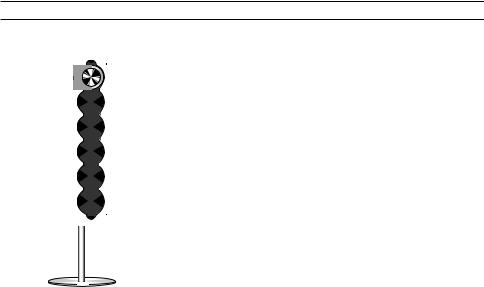
Fig. 1: The BeoSound 9000 |
setup situations mentioned |
If you wish to hang your Beo- |
||||||||
placed in a vertical position |
here – this is very important |
Sound 9000 on a gypsum wall, |
||||||||
using the Stand type 2055. |
for the functioning of the CD |
using one of the brackets, we |
||||||||
When placed like this, the CD |
player! |
recommend that at least one |
||||||||
mechanism must be centered |
■ In the section “Ready for |
mounting screw be a lag screw, |
||||||||
for a vertical position. |
use…” is described how to turn |
which is screwed securely into |
||||||||
The Stand is supplied with two |
the close-up operation panel |
a vertical wall stud. |
||||||||
different sets of feet: |
(and the display) so it can be |
■ When hanging the BeoSound |
||||||||
– |
spikes for use on a carpeted |
read from your preferred angle. |
9000 on the wall (as shown in |
|||||||
|
floor |
■ The BeoSound 9000 is |
figs 2, 3, and 7) we recommend |
|||||||
– |
rubber feet for use on a non- |
designed for use in dry |
that you conceal the cables |
|||||||
|
carpeted floor |
environments only, and for use |
using the optional Cable Cover |
|||||||
|
|
|
|
|
|
|
|
|
within a temperature range |
type 2062. |
Do not lift or move the Stand |
of 10 – 40° C (50 – 105° F). |
This cable cover has an overall |
||||||||
around while the BeoSound |
■ Avoid placing the BeoSound |
length of 75 cm (29½"). The |
||||||||
9000 is mounted. |
9000 in direct sunlight or direct |
folder enclosed with the cable |
||||||||
|
|
|
|
|
|
|
|
|
artificial light (e.g. a spotlight), |
cover describes how and where |
|
|
|
|
|
|
|
|
|
or near objects generating |
to fasten it in relation to the |
|
|
|
|
|
|
|
|
|
electrical noise (e.g. dimmers), |
different wall brackets. |
|
|
|
|
|
|
|
|
|
as this will reduce the sensitivity |
As you can see, we have used |
|
|
|
|
|
|
|
|
|
of the remote control receiver. |
two cable covers in fig. 2, and |
|
|
|
|
|
|
|
|
|
■ Place the BeoSound 9000 so |
one in figs 3 and 7, respectively. |
|
|
|
|
|
|
|
|
|
that ventilation will not be |
When mounted correctly this |
|
|
|
|
|
|
|
|
|
impeded, and remember to |
ensures that the BeoSound |
|
|
|
|
|
|
|
|
|
leave enough space above or |
9000 is hung at the optimal |
|
|
|
|
|
|
|
|
|
in front of the BeoSound 9000 |
height for easy access to the CD |
|
|
|
|
|
|
|
|
|
for the glass door to open, and |
compartments. The two |
|
|
|
|
|
|
|
|
|
to facilitate close-up operation. |
different heights also takes the |
movement of the glass door into consideration.
■ When lifting the BeoSound 9000 out of the box we recommend that you, in order to avoid fingermarks on the surfaces, use the two foam packing shells placed at each end of the BeoSound 9000.
5
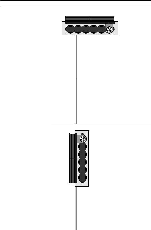
Fig. 2: The BeoSound 9000 hung flat on the wall in a high horizontal position using the Bracket type 2054, and two Cable Covers type 2062. When placed like this the CD mechanism must be centered for a horizontal position.
Fig. 3: The BeoSound 9000 hung flat on the wall in a vertical position using the Bracket type 2063, and one Cable Cover type 2062. When placed like this the CD mechanism must be centered for a vertical position.
 Loading...