

Badger Meter M2000 Operating Manual

M-Series® M2000
PROFIBUS DP
MAG-UM-01409-EN-04 (November 2016)
User Manual

M-Series® M2000, PROFIBUS DP
CONTENTS
About This Manual. . . . . . . . . . . . . . . . . . . . . . . . . . . . . . . . . . . . . . . . . . . . . . . . . . . . . . . . . . . . . . . . . . . . . .3
Denitions . . . . . . . . . . . . . . . . . . . . . . . . . . . . . . . . . . . . . . . . . . . . . . . . . . . . . . . . . . . . . . . . . . . . . . . .3
Scope . . . . . . . . . . . . . . . . . . . . . . . . . . . . . . . . . . . . . . . . . . . . . . . . . . . . . . . . . . . . . . . . . . . . . . . . . . .3
Introduction. . . . . . . . . . . . . . . . . . . . . . . . . . . . . . . . . . . . . . . . . . . . . . . . . . . . . . . . . . . . . . . . . . . . . . . . . .3
Installation. . . . . . . . . . . . . . . . . . . . . . . . . . . . . . . . . . . . . . . . . . . . . . . . . . . . . . . . . . . . . . . . . . . . . . . . . . .4
Prerequisites. . . . . . . . . . . . . . . . . . . . . . . . . . . . . . . . . . . . . . . . . . . . . . . . . . . . . . . . . . . . . . . . . . . . . . .4
Installing the Daughterboard . . . . . . . . . . . . . . . . . . . . . . . . . . . . . . . . . . . . . . . . . . . . . . . . . . . . . . . . . . . .4
System Conguration. . . . . . . . . . . . . . . . . . . . . . . . . . . . . . . . . . . . . . . . . . . . . . . . . . . . . . . . . . . . . . . . . . . .7
Master Class 1 . . . . . . . . . . . . . . . . . . . . . . . . . . . . . . . . . . . . . . . . . . . . . . . . . . . . . . . . . . . . . . . . . . . . . 7
Master Class 2. . . . . . . . . . . . . . . . . . . . . . . . . . . . . . . . . . . . . . . . . . . . . . . . . . . . . . . . . . . . . . . . . . . . . .7
General Station Data (GSD) Files for Master Class 1 Devices . . . . . . . . . . . . . . . . . . . . . . . . . . . . . . . . . . . . . . . . .8
Cyclic Data Exchange . . . . . . . . . . . . . . . . . . . . . . . . . . . . . . . . . . . . . . . . . . . . . . . . . . . . . . . . . . . . . . . . .8
Identity Numbers . . . . . . . . . . . . . . . . . . . . . . . . . . . . . . . . . . . . . . . . . . . . . . . . . . . . . . . . . . . . . . . . . . .9
Network Baud Rate . . . . . . . . . . . . . . . . . . . . . . . . . . . . . . . . . . . . . . . . . . . . . . . . . . . . . . . . . . . . . . . . . .9
Slave Device Network Address . . . . . . . . . . . . . . . . . . . . . . . . . . . . . . . . . . . . . . . . . . . . . . . . . . . . . . . . . . . 9
Data Management. . . . . . . . . . . . . . . . . . . . . . . . . . . . . . . . . . . . . . . . . . . . . . . . . . . . . . . . . . . . . . . . . . . . .10
Physical Block . . . . . . . . . . . . . . . . . . . . . . . . . . . . . . . . . . . . . . . . . . . . . . . . . . . . . . . . . . . . . . . . . . . . .10
Transducer Block . . . . . . . . . . . . . . . . . . . . . . . . . . . . . . . . . . . . . . . . . . . . . . . . . . . . . . . . . . . . . . . . . . .12
Analog Input Functional Block . . . . . . . . . . . . . . . . . . . . . . . . . . . . . . . . . . . . . . . . . . . . . . . . . . . . . . . . . . 17
Compliance . . . . . . . . . . . . . . . . . . . . . . . . . . . . . . . . . . . . . . . . . . . . . . . . . . . . . . . . . . . . . . . . . . . . . . . . . 19
Page ii November 2016MAG-UM-01409-EN-04
M2000
DSP
Profibus DP
Daughter
Board
Modbus RTU
Profibus-DP
INTELLIGENT
HOST
About This Manual
ABOUT THIS MANUAL
Denitions
DD Device Description
DP PROFIBUS® protocol for (D)ecentralized or distributed (P)eripherals. Defines the basic functions related to
cyclic data exchange.
DPV1 Extended functions of PROFIBUS DP that allow acyclic communication for parameter configuration. DP is
traditionally only suited for transfer of measured variables.
DTM Device Type Manager
GSD General Station Data file. Driver file that defines the behavior of the PROFIBUS DP device over PROFIBUS.
The driver file describes capabilities like data-rates, dynamic variables, etc. A PROFIBUS DP master uses the
GSD file to start cyclic communication with the device.
PA Profile The PA profile standardizes the basic functions for all the different PROFIBUS devices.
PV Process Value
SPS Alternate abbreviation for PLC (Programmable Logic Controller)
User Units Defined by configuration of the meter’s volume unit or flow unit
Scope
This document shall discuss the supported features of PROFIBUS DP, how these features are related to the M2000, and the
special considerations and type of data that is accessible over PROFIBUS DP. This document assumes general understanding
of the PROFIBUS DP protocol by the reader. For further information regarding the PROFIBUS DP Protocol, refer to
www.PROFIBUS.com.
The M2000 PROFIBUS DP daughterboard supports PROFIBUS DPV1 protocol. This is an extended protocol that allows for
acyclic communication for parameter configuration.
In addition, the M2000 PROFIBUS DP daughterboard supports PA Profile Version 3.0.
INTRODUCTION
PROFIBUS is an international, vendor-independent, bus standard for a wide range of applications in manufacturing,
production, process and building automation, and other automation control industries.
The PROFIBUS family comprises three types of protocol, PROFIBUS DP, PROFIBUS-PA and PROFIBUS-FMS, and each is used for
different tasks. Only PROFIBUS DP is considered in this document.
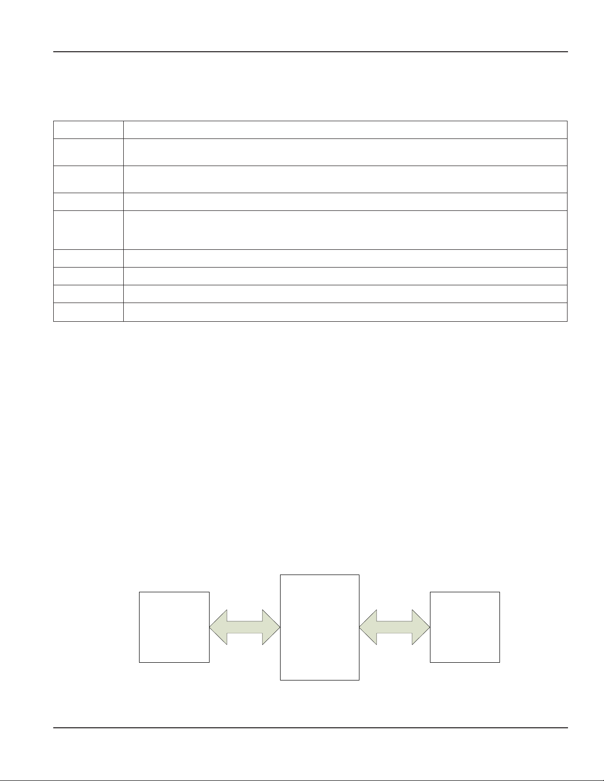
PROFIBUS DP (Decentralized Periphery) is a rapid and low cost communication connection designed for high speed data
transmission. PROFIBUS DP is accomplished with an M2000 through a PROFIBUS DP to MODBUS RTU signal conversion board,
referred to as the PROFIBUS DP daughterboard throughout the remainder of this document.
Figure 1: PROFIBUS DP-to-MODBUS RTU commands
Page 3 November 2016 MAG-UM-01409-EN-04
Installation
INSTALLATION
Prerequisites
Installing a PROFIBUS DP daughterboard into an M2000 requires firmware revision v1.10 or later.
Installing the Daughterboard
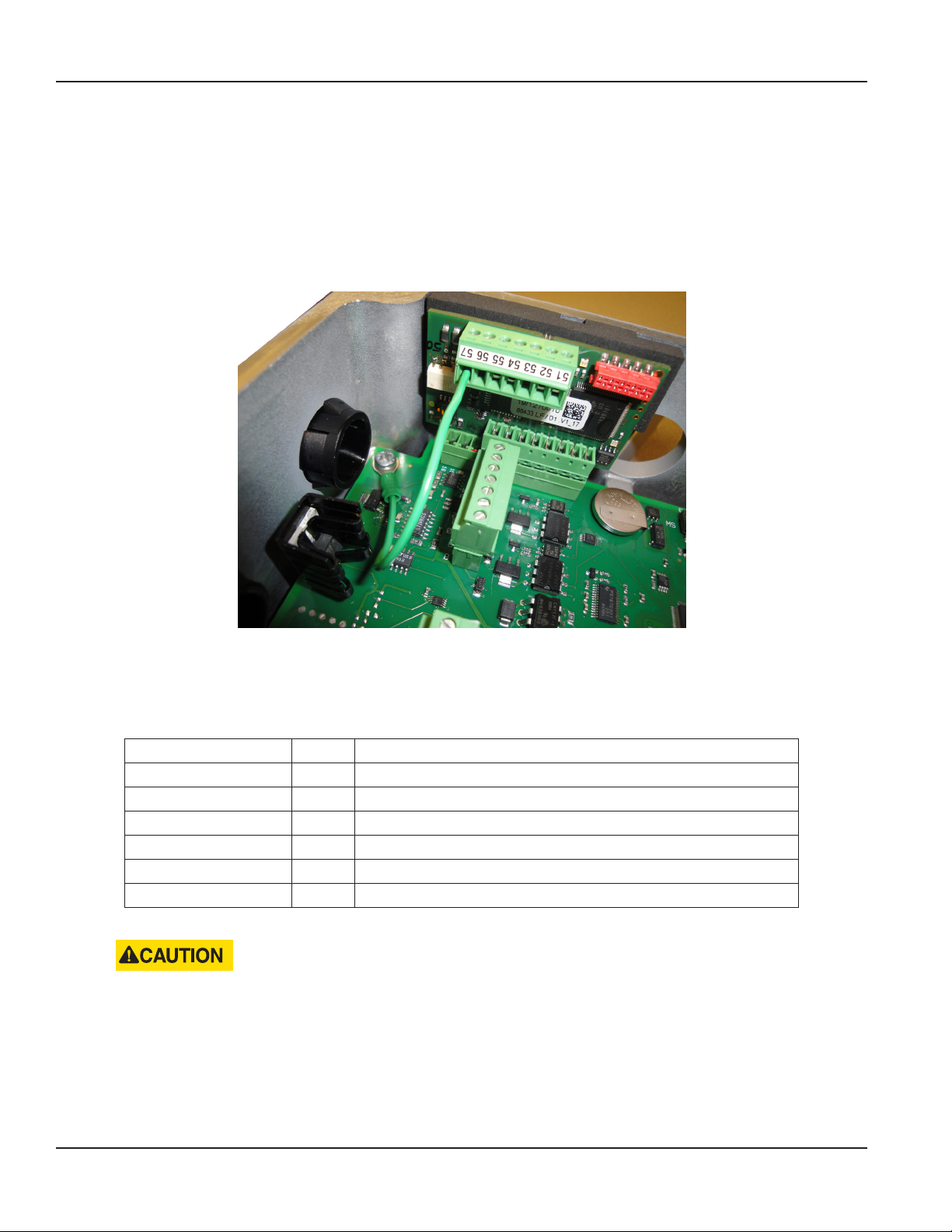
The PROFIBUS DP daughterboard connects to the 11-pin connector labeled COMMUNICATION on the main amplifier.
Figure 2: Daughterboard connection
Follow these steps to install the daughterboard.
1. Prior to installing the daughterboard, verify or congure the M2000 Communication Port B.
The port settings are located at Main Menu > Communications > Port B Settings.
Parameter Value Comments
Port Address 001 Mandatory value of 001
Extended Port Address — Application specific. Sets PROFIBUS DP address of module
Baud Rate 38400 PROFIBUS DP Daughterboard auto-bauds
Data Bits 8 Mandatory value of 8
Parity EVEN Mandatory value of EVEN
Stop Bits 1 Mandatory value of 1
2. Power o the M2000.
DISCONNECT THE INPUT POWER BEFORE ACCESSING THE EQUIPMENT.
This step is important for the M2000 to properly recognize the PROFIBUS DP daughterboard.
3. Prior to inserting the daughterboard, install the foam insulation pad as shown Figure 3 on page 5. Be sure to align the
groove with the two screws attaching the detector or wall mount bracket to the enclosure. The primary purpose of this
pad is to ensure the daughterboard is insulated from the enclosure wall. It is important to install this pad ush with the top
of the enclosure wall.
Page 4 November 2016MAG-UM-01409-EN-04

Installation
Apply insulation pad
flush with the top of
the housing.
Figure 3: Installing foam insulation pad
4. Insert the 8-pin daughterboard into the 11-pin connector.
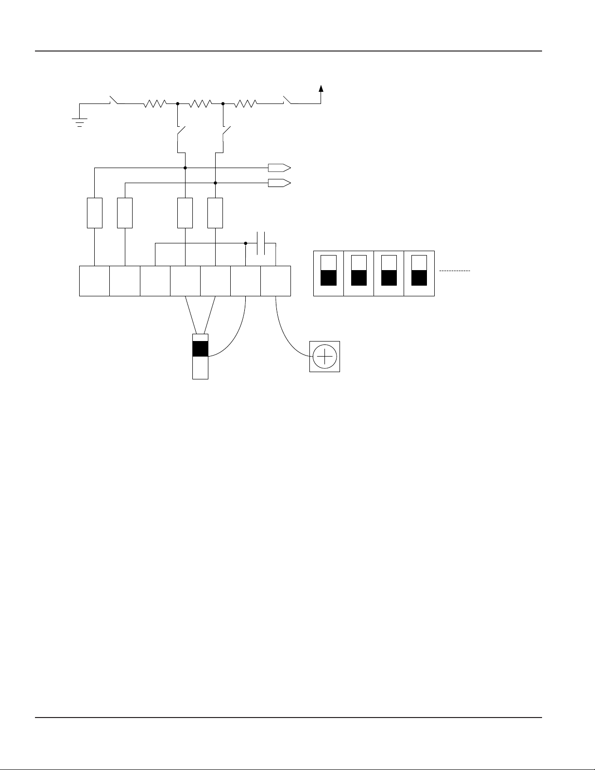
5. Use the following information to make appropriate wiring of signals to the 7-pin customer connector. See "Figure 4: Signal
wiring diagram" on page 6.
Pin Number Pin Description Comments
51 RXD/TXD-P Receive Data / Transmission Data – Plus
52 RXD/TXD-N Receive Data / Transmission Data – Negative
53 Shield —
54 RXD/TXD-P Receive Data / Transmission Data – Plus
55 RXD/TXD-N Receive Data / Transmission Data – Negative
56 Shield —
57 Chassi —
Page 5 November 2016 MAG-UM-01409-EN-04
Installation
5V
390 Ω
1
220 Ω
390 Ω
4
GND
3
2
RXD/TXD-P
RXD/TXD-M
FB
FB
5251
FB
5453 5655
+ -
FB
Closed
Open
43
57
1
2
Switch S1
Chassi
Shield
PCB
Fastening
Screw
Figure 4: Signal wiring diagram
6. Power on the M2000.
7. Allow time for the daughterboard to properly power up and be recognized by the M2000 before navigating the menus.
This time is typically 5 seconds. If the PROFIBUS DP daughterboard is not recognized, then the M2000 should be
power cycled.
8. Verify recognition of the PROFIBUS DP daughterboard. Navigate to Main Menu > Info > Help. The Daughterboard Info eld
indicates the Daughterboard Type is PROFIBUS DP.
Page 6 November 2016MAG-UM-01409-EN-04
 Loading...