


Research Control Valve
Series 9000
RESEARCH® CONTROL
Valves
Installation &
Operation Manual
BadgerMeter,Inc.
®
940467
1-02

TABLE OF CONTENTS
Page
General .............................................................................................................................................. 1
Installation ......................................................................................................................................... 1
Disassembly and Reassembly ........................................................................................................... 1
Replacing Trim Sets ........................................................................................................................... 1
Installing Trim Sets ............................................................................................................................. 2
Lapping Sequence ............................................................................................................................. 3
Assembly ........................................................................................................................................... 3
Stroke Adjustment and Pressure Test ................................................................................................ 4
Packing, Chevron Ring ....................................................................................................................... 5
Braided Teflon and Graphoil Packing .................................................................................................. 5
Bellows .............................................................................................................................................. 7
General ............................................................................................................................................ 7
Removal of Assembly from Valve .................................................................................................... 7
Removing lnnervalve from Bellows Assembly & Seat from Body .................................................... 8
Installing Bellows Seal Assembly, Innervalve & Seat....................................................................... 8
Valve Positioners ............................................................................................................................... 9
General ............................................................................................................................................ 9
Integral Mounting ............................................................................................................................. 9
Range Springs ................................................................................................................................. 9
Top Loading, Air-to-Close ................................................................................................................. 9
Bottom Loading, Air-to-Open .......................................................................................................... 10
Adjusting Zero ............................................................................................................................... 10
Servicing........................................................................................................................................ 10
Terminology ...................................................................................................................................... 11
Notes ............................................................................................................................................... 12
Special Information .......................................................................................................................... 13
General
The purpose of these instructions is to supply pertinent
information for installation of original equipment, repair,
adjustments, retrimming, repacking and other information necessary to achieve the best possible service
from Research Control Valves.
Research Control Valves are engineered, designed, and
manufactured with the end user in mind. Most parts are
interchangeable with any other like assembly. The inner
components (spare trims) are available in 39 different
flow coefficient (Cv) sizes and in many different materials compatible with most process conditions.
Installation
After inspecting the valve (or valves) and determining
that the valve (or valves) meets the specifications, install as follows:
1. Normal installation is directly into any 1/4", 1/2",
3/4", or 1” piping system with flow direction arrow on
body pointing downstream. This allows the stem packing to see the lowest pressure conditions after the
pressure drop occurs. It should be noted that chevron
ring stem packing is a dynamic seal that needs pressure to be energized.
2. Valves, especially plastic, should be bracket mounted
in high vibration areas or where they may be subjected
to damage from shock. If necessary, provide as required,
bypass, manual block valve, filters, etc. When installing valves that have the Low Flow “P” Series innervalves,
small micron filters should be used where process permits.
to hold unbalance created by higher pressure on actual
application. It should be noted that on air-to-close valves
with no pressure, the travel indicator will show over travel.
With 3 PSIG to actuator, the indicator will be very close
to the open position.
Disassembly and Reassembly
(Best done at instrument shop bench)
For the purpose of these instructions, consider the
topworks or actuator as a complete sub-assembly not
to be dismantled except for replacing diaphragms or
topworks packing. The only necessary topworks adjustment is made with the spring adjuster and/or the
zero adjustment on positioner-equipped valves (see
paragraph on Positioners). To position the stem, travel
in relation to the 3-15, 3-9, 9-15 PSIG etc. instrument
signal operating the valve.
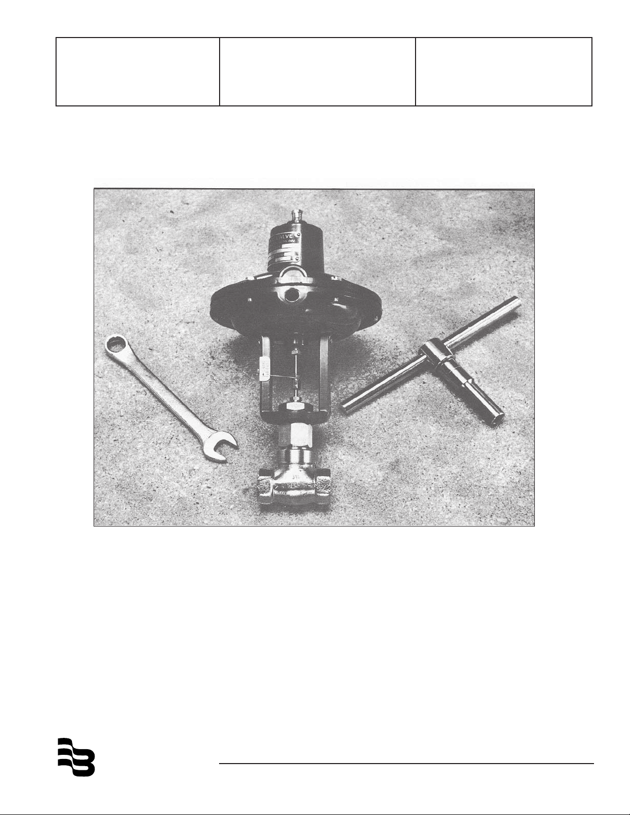
Replacing Trim Sets
Installing innervalve trim sets is accomplished with the
body and bonnet subassembly separated from the
topworks using appropriate wrenches. (Tool kits are
available at a nominal cost for 1/4”, 1/2”, 3/4”, and 1”
valves.) To separate the body bonnet assembly from
the topworks on ATO valves, apply 6-9 PSIG instrument air to the operator, lifting innervalve off seat to
prevent damage to the valve seating surfaces. (Not
necessary for ATC valves.)
3. Connect instrument air supply to diaphragm case
using appropriate NPT fittings (1/8" NPT for 1/4" valves
and 1/4" NPT for 1/2", 3/4", and 1” valves) to the desired tubing size adaptor (normally 1/4” tube fittings).
All connections to standard positioners, Moore products or Badger
®
, are 1/4" NPT. (For positioner data, see
paragraph under Positioners.)
4. All standard production valves as shipped are adjusted and preset at the factory with 90 PSIG air piped
to the inlet port of the body. Air-to-open valves are adjusted to come off seat at approximately 3.25 PSIG
instrument signal and be fully opened at 15 PSIG. Airto-close valves are set to close when signal is at 14.75
PSIG and be fully open at 3 PSIG. Process conditions
may dictate additional adjustment of the spring adjuster
FIG. 1
1
1 .With innervalve off seat, use two open-end wrenches
(1/4" for 1/4" valves and 3/8" for 1/2", 3/4", and 1”
valves), one holding the stem connector in position,
and with the other loosen the topworks stem nut above
travel pointer; remove travel pointer.
2. With valve body in vise (clamp on ends), loosen the
yoke to bonnet locknut (yoke locknut) with a slotted
end wrench (7/8" boxed end for 1/4" valves, 1-1/8" for
1/2", 3/4" and 1" valves), and unscrew completely.
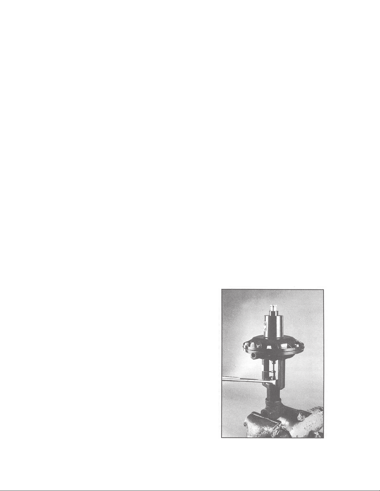
3. With the open-end wrench, turn the stem connector
counterclockwise (right hand threads), unscrewing from
the topworks stem completely. (Fig. 1)
4. Remove topworks from body bonnet assembly.
5. With the valve body in vise, loosen and unscrew
bonnet from body using open-end or crescent wrench.
Installing Trim Sets
(Matching pairs do not separate)
With all parts cleaned in an appropriate solvent, install
desired trim set in body bonnet assembly as follows:
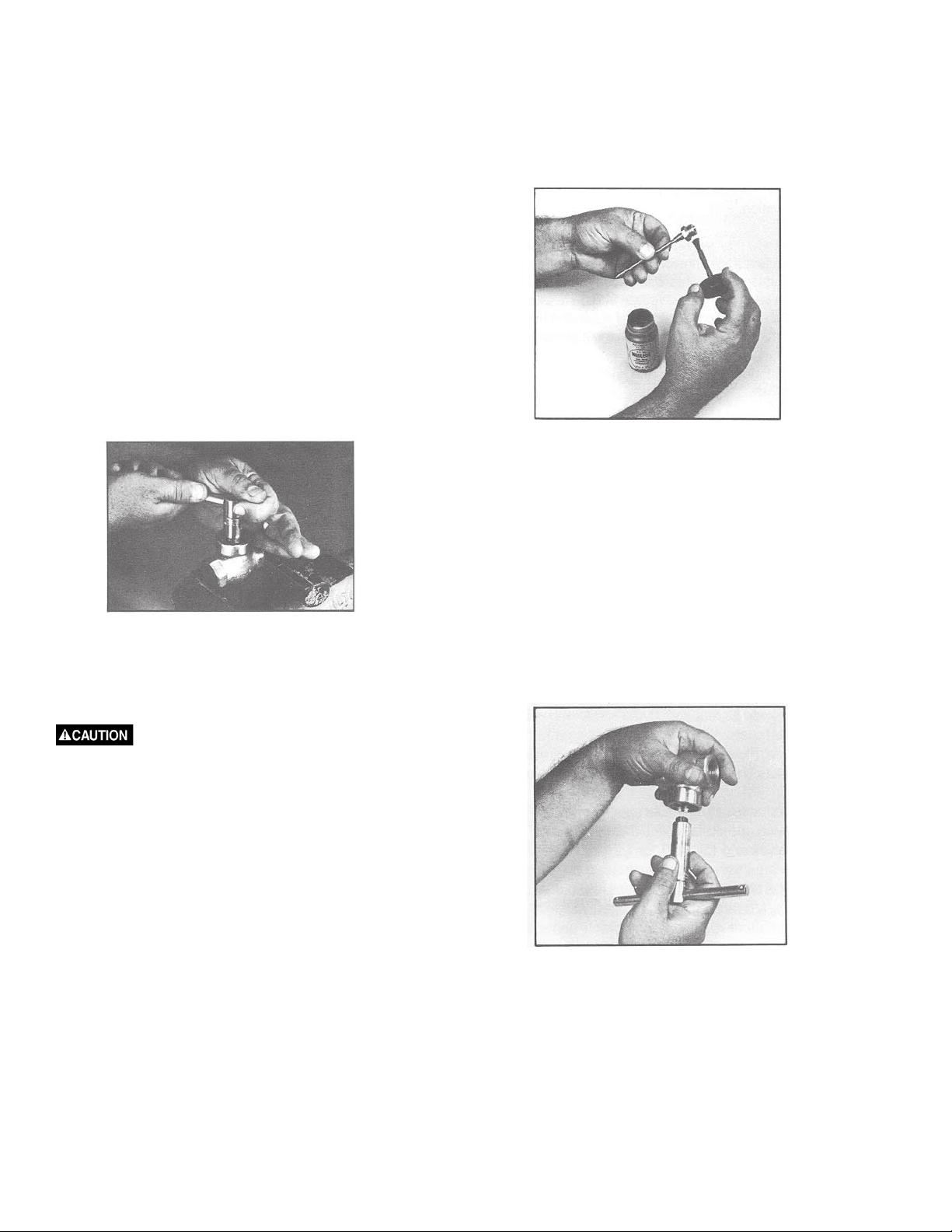
FIG. 3
1. With trim as shown in Figure 3, apply a coating of
Neolube (graphite dry film lubricant), process permitting,
to the threads and seating surfaces of the seat. Air dry
for 30 seconds. Do not use any thread sealing
compounds containing metal particles. NOTE: New
replacement innervalves, come pre-coated with NeoLube
except those specially cleaned.
FIG. 2
6. Remove seat from body using a deep thin wall socket
and T-handle assembly (3/8" hexagon for 1/4" valves,
5/8" hexagon for 1/2", 3/4" hexagon for 3/4"valves, and
15/16" hexagon for 1” valves).
Some purchased long set sockets
(heavyduty) will not fit body cavity without turning
O.D. to fit past body threads.
(Fig. 2)
7. Most standard innervalves “K” through “P18” in 1/4"
valves and “F” through the “P” series trim in 1/2" valves
can be removed upward from the bonnet through the
packing, all others by removing stem connector and
withdrawing downward through the packing. When
removing the larger trims down through packing, it is
best to withdraw stems until threaded portion is in
contact with packing and then rotate stem and allow
the threads to screw through the packing area.
2. Remove seat from innervalve and place hex first into
the long set socket wrench and T-handle assembly.
NOTE: Tissue paper can be stuffed into the socket to
prevent seat from falling through.
FIG. 4
3. With body inverted in palm of hand as shown in
Figure 4, start seat threads into body, invert body and
tighten seat. Do not over-torque. Standard torque figures
using new parts at the factory are: 10/11 ft/pounds on
“P” trim seats, 8.5 ft/pounds on other 1/4" seats, 35 ft/
pounds on 1/2", 3/4" and 1” seats. It should be noted
that torque figures are applicable to new parts and may
not be the same for used parts. For longest service life,
on new or used parts, it’s best to use procedure detailed
in paragraph 4.
2
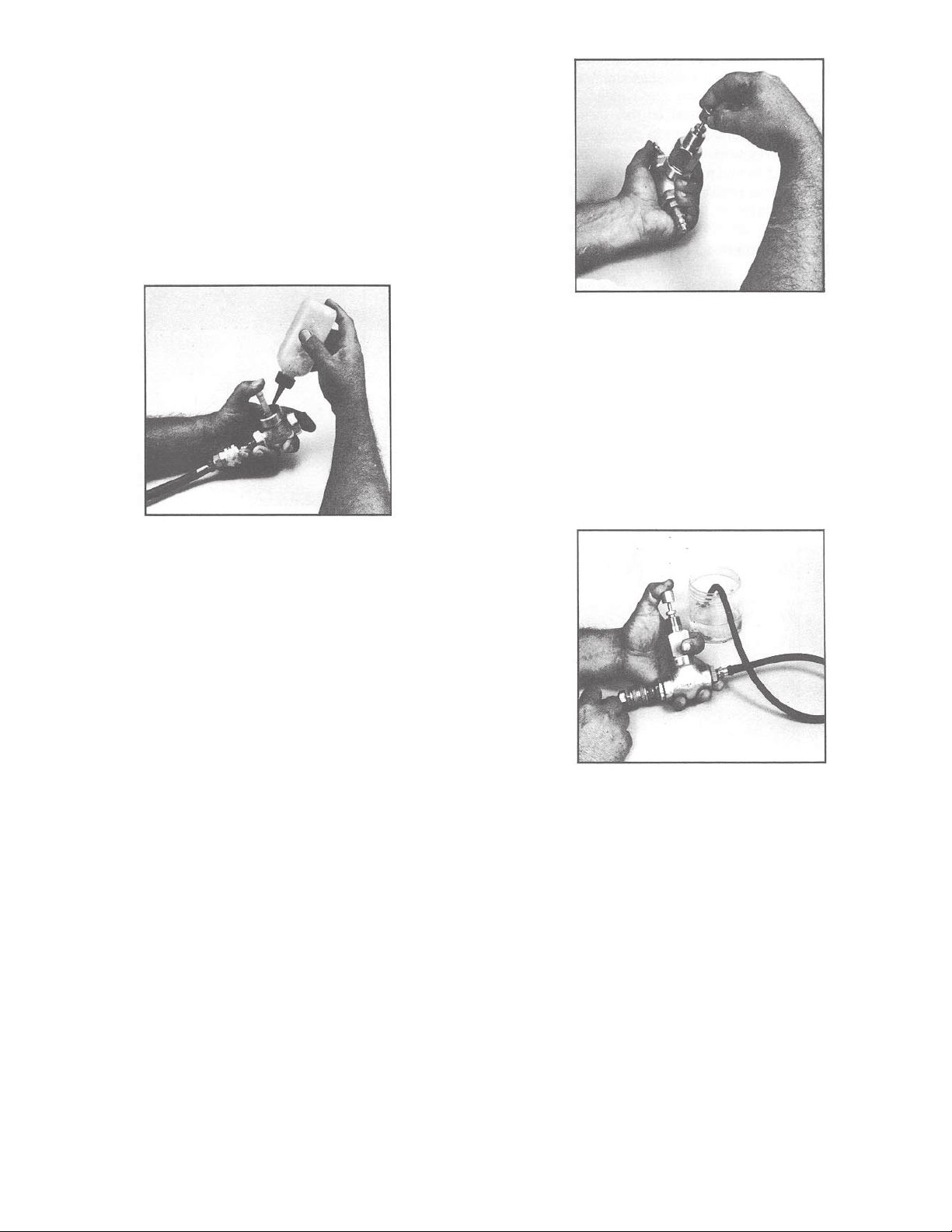
4. Torque seat firmly into body with the short T- handle
assembly. Check seat to body seal, by making body a
bubble chamber, using a pointed plastic plug in seat to
seal as shown in Figure 5 with downstream port plugged
and 50 psi air pressure upstream, check for leak. If
leak exists, re-torque seat and recheck until bubbletight seal is accomplished. On smaller letter or “P” series
trim sets, over-torquing seat in the body can reduce the
orifice size to where interference between innervalve
and seat can cause a premature mechanical failure
(galling) when stroking valve.
FIG. 6
clockwise, counterclockwise motion between the thumb
and forefinger, lifting the innervalve off seat and
repositioning periodically to achieve a uniform lap ring.
After each lapping operation, remove bonnet from body
and clean innervalve and seat from body. Clean seat by
submerging body in solvent and swabbing orifice with
wetted pipe cleaner and blow dry with air. After cleaning,
reassemble and check leak rate as shown in Figure 7.
Caution should be taken to not overlap.
FIG. 5
5. With body in vise, again clamping across ends of
body not sides of body, place body bonnet gasket in
place. (Process permitting, coat each side of gasket
with lubricant such as Dow Corning or Dupont Krytox
valve seal.) With the stem section of the trim set
installed in the bonnet, coat the bonnet threads (body
end) with lubricant.
6. Screw bonnet into body and tighten with open-end or
crescent wrench. Apply the proper torque to bonnet/
body joint as listed on the back side of individual
technical briefs.
7. Stroke innervalve manually to check for misalignment. Should misalignment exist, check straightness
of innervalve or packing. (See Packing Installation.)
NOTE: All replacement trim sets have been prelapped
at the factory. When installed per instructions, trims
should leak no more than 1/10 of one percent of
maximum flow for the given size, (ANSI Class III). If
necessary, with care, bubble-tight shutoff can normally
be achieved by lapping in seating surfaces with the
innervalve set installed in the body bonnet assembly
using lapping compound (white aluminum oxide 38-1000
grit) with the packing removed, using the packing glands
as the upper guide (brass lap bushing available at
factory). See Figure 6. Lapping should be done with a
FIG. 7
Lapping Sequence
Lap for about 30 seconds, clean and check leak rate;
repeat sequence until desired shutoff is achieved. If
after lapping three or four times leak still exists, check
the seating surfaces of both innervalve and seat for
excess nicks, scratches, or indication of galling if the
trim has previously been in service. Do not lap for
shutoff any of the “P” series trims.
Assembly
1. With body in vise, place topworks yoke on bonnet
with yoke locknut slipped over the stem connector and
down on bonnet threads (6-9 PSIG air on air-to-open
topworks).
2. With topworks in correct position relative to the
centerline of the body, tighten yoke locknut using a
boxed-end (slotted) wrench.
3
 Loading...