


 Loading...
Industrial Process Controller
Model PC200
CTL-UM-00483-EN-07 (April 2017)
User Manual

Industrial Process Controller, Model PC200
Page ii |
CTL-UM-00483-EN-07 |
April 2017 |

|
User Manual |
|
|
|
|
|
CONTENTS |
|
Scope of This Manual |
5 |
|
Unpacking the PC200 |
5 |
|
Safety Considerations |
5 |
|
Safety Terminology and Symbols |
5 |
|
Safety Instructions |
6 |
|
Disposal |
6 |
|
Safety Rules and Precautionary Measures |
6 |
|
PC200 Batch Controller Description |
7 |
|
Functions and Features |
7 |
|
Flow Meter Input |
7 |
|
Control Inputs |
7 |
|
Control Outputs |
7 |
|
Power Supply |
7 |
|
Configuration of the Unit |
8 |
|
Display Information |
8 |
|
Installation |
9 |
|
Installation Conditions |
9 |
|
Mounting the PC200 |
9 |
|
Wiring the PC200 |
11 |
|
Voltage Selection Sensor Supply |
11 |
|
Terminal Connectors |
11 |
|
Operation |
17 |
|
Control Panel |
17 |
|
Operator Information and Functions |
18 |
|
Operator Alarms |
20 |
|
Configuration |
21 |
|
Programming the Setup Level |
21 |
|
Transmitter Connections |
27 |
|
Transmitter Pulses Per Unit |
28 |
|
Maintenance |
29 |
|
Repair |
29 |
|
Technical Specifications |
30 |
|
General . . . . . . . . . . . . . . . . . . . . . . . |
. . . . . . . . . . . . . . . . . . . . . . . . . . . . . . . . . . . . . . . . . . . . . . . . . 30 |
|
Troubleshooting |
32 |
|
Record of Configuration Settings |
33 |
|
April 2017 |
CTL-UM-00483-EN-07 |
Page iii |

Industrial Process Controller, Model PC200
Page iv |
CTL-UM-00483-EN-07 |
April 2017 |

User Manual
SCOPE OF THIS MANUAL
This manual is divided into two main sections:
•The daily use of the unit is described in “Operation” on page 17. These instructions are meant for users.
•The remaining chapters provide a detailed description of all software settings and hardware installation guidance. These instructions and are meant exclusively for electricians/technicians.
This manual describes the standard unit as well as most of the options available. For additional information, please contact your supplier.
IIMPORTAN
Read this manual carefully before attempting any installation or operation.
Keep the manual in an accessible location for future reference.
UNPACKING THE PC200
NNOTE: If damage to the shipping container is obvious, request that the carrier be present when the product is unpacked. All claims for equipment damage during transit are the sole responsibility of the recipient.
After carefully unpacking the unit, check for any visible sign of damage. If found, notify the carrier for insurance purposes and call the factory for possible replacement. Keep all packing material in the event that the unit must be returned to the factory.
NNOTE: Operating temperature is 32…130° F (0…55° C) with a maximum humidity of 85% non-condensing. Always select a mounting location with proper ventilation and environmental protection.
SAFETY CONSIDERATIONS
Safety Terminology and Symbols
Indicates a hazardous situation, which, if not avoided, is estimated to be capable of causing death or serious personal injury.
Indicates a hazardous situation, which, if not avoided, could result in severe personal injury or death.
Indicates a hazardous situation, which, if not avoided, is estimated to be capable of causing minor or moderate personal injury or damage to property.
April 2017 |
CTL-UM-00483-EN-07 |
Page 5 |

Industrial Process Controller, Model PC200
Safety Instructions
•LIFE SUPPORT APPLICATIONS: THE PC200 IS NOT DESIGNED FOR USE IN LIFE SUPPORT APPLIANCES, DEVICES, OR SYSTEMS WHERE MALFUNCTION OF THE PRODUCT CAN REASONABLY BE EXPECTED TO RESULT IN A PERSONAL INJURY. CUSTOMERS USING OR SELLING THESE PRODUCTS FOR USE IN SUCH APPLICATIONS DO SO AT THEIR OWN RISK AND AGREE TO FULLY INDEMNIFY THE MANUFACTURER AND SUPPLIER FOR ANY DAMAGES RESULTING FROM SUCH IMPROPER USE OR SALE.
•ELECTROSTATIC DISCHARGE INFLICTS IRREPARABLE DAMAGE TO ELECTRONICS! BEFORE INSTALLING OR OPENING THE UNIT, INSTALLERS MUST DISCHARGE THEMSELVES BY TOUCHING A WELL-GROUNDED OBJECT.
•THIS UNIT MUST BE INSTALLED IN ACCORDANCE WITH THE EMC (ELECTROMAGNETIC COMPATIBILITY) GUIDELINES.
•CONNECT A PROPER GROUNDING TO THE ALUMINUM CASING AS INDICATED.
Disposal
Dispose of this product according to local regulations regarding waste electronic equipment. The separate collection and recycling of your waste equipment will help to conserve natural resources and ensure that it is recycled in a manner that protects the environment.
Safety Rules and Precautionary Measures
The manufacturer accepts no responsibility whatsoever if the following safety rules and precaution instructions and the procedures as described in this manual are not followed.
•Modifications of the PC200 implemented without preceding written consent from the manufacturer will result in the immediate termination of product liability and warranty period.
•Installation, use, maintenance, and servicing of this equipment must be carried out by authorized technicians.
•Check the mains voltage and information on the manufacturer's plate before installing the unit.
•Check all connections, settings and technical specifications of the various peripheral devices with the PC200 supplied.
•Open the casing only if all leads are free of potential.
•Never touch the electronic components (ESD sensitivity).
•Never expose the system to heavier conditions than allowed according to the casing classification (see manufacturer's plate and “Installation Conditions” on page 9).
•If the operator detects errors or dangers, or disagrees with the safety precautions taken, then inform the owner or principal responsible.
•Adhere to the local labor and safety laws and regulations.
Page 6 |
CTL-UM-00483-EN-07 |
April 2017 |

User Manual
PC200 BATCH CONTROLLER DESCRIPTION
Functions and Features
The batch controller model PC200 is a microprocessor-driven instrument designed for batching and filling both small and large quantities, as well as displaying total, accumulated total and flow rate.
This product is designed with a focus on:
•Ease-of-use with the numerical keyboard.
•Ruggedness for its application with a robust enclosure, keyboard and proper mechanical relays.
•Clear operator information: all relevant data can be monitored in one glance.
•User-friendly installation with quality plug-and-play terminals; suitable for both AC and DC applications (standard).
•A wide range of inputs, outputs and functions for a broad fulfillment in many applications.
Flow Meter Input
One flow meter: a passive or active pulse signal output can be connected to the PC200. The input circuit supports low and high frequency flow meters. A power supply is available to power the sensor with 8 / 12 or 24V DC.
Control Inputs
The PC200 has six control inputs:
•Start
•Hold
•Resume
•Reset totalizer
•Reset cycle counter
•Lockout the entire keyboard
Control Outputs
The PC200 has five control outputs—two mechanical relay outputs and three transistor outputs. The two mechanical relay outputs (make and break) are used for batching with two-stage control or one-stage control. Three transistor outputs are for connection to PLCs or other controlling equipment. The function of relay R2 and the transistor outputs can be configured to:
•Batching
•Two-stage control
•High flow rate alarm
•Low flow rate alarm
•No flow alarm
•Any alarm
•Scaled pulse output
•Pre-warn or end of batch signal
Power Supply
AC power supply: as standard, the PC200 will operate on 110…230V AC.
DC power supply: as standard, the PC200 can also operate on 24V DC.
April 2017 |
CTL-UM-00483-EN-07 |
Page 7 |

Industrial Process Controller, Model PC200
Configuration of the Unit
The PC200 is designed for many types of applications. Use the SETUP level to configure your PC200 to your specific requirements. For details, see “Configuration” on page 21 and “Record of Configuration Settings” on page 33.
The SETUP level includes several important features, such as K-factors, measurement units and selection of the control outputs. All settings are stored in EEPROM memory and will not be lost in the event of power failure.
Display Information
The PC200 has a large transflective LCD with a bright LED backlight and displays symbols and digits for measuring units, status information and keyword messages.
All total, accumulated total and batch counter information is stored in EEPROM memory and will not be lost in the event of power failure.
Page 8 |
CTL-UM-00483-EN-07 |
April 2017 |
User Manual
INSTALLATION
•MOUNTING, ELECTRICAL INSTALLATION, STARTUP AND MAINTENANCE OF THIS INSTRUMENT MAY ONLY BE CARRIED OUT BY TRAINED PERSONNEL AUTHORIZED BY THE OPERATOR OF THE FACILITY. PERSONNEL MUST READ AND UNDERSTAND THIS OPERATING MANUAL BEFORE CARRYING OUT ITS INSTRUCTIONS.
•THE PC200 MAY ONLY BE OPERATED BY PERSONNEL WHO ARE AUTHORIZED AND TRAINED BY THE OPERATOR OF THE FACILITY. OBSERVE ALL INSTRUCTIONS IN THIS MANUAL.
•ENSURE THAT THE MEASURING SYSTEM IS CORRECTLY WIRED ACCORDING TO THE WIRING DIAGRAMS. PROTECTION AGAINST ACCIDENTAL CONTACT IS NO LONGER ASSURED WHEN THE HOUSING COVER IS REMOVED OR THE PANEL CABINET HAS BEEN OPENED (DANGER FROM ELECTRICAL SHOCK). THE HOUSING MAY ONLY BE OPENED BY TRAINED PERSONNEL.
•OBEY ALL SAFETY PRECAUTIONS MENTIONED IN “Safety Considerations” on page 5.
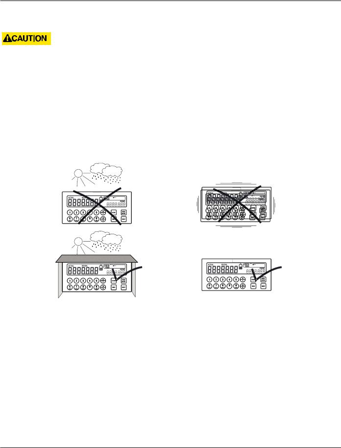
Installation Conditions
Figure 1: Acceptable installation conditions
Consider the IP classification of the casing (see the manufacturer's plate) when selecting a location for the PC200. An IP65 (NEMA 4X) casing should NEVER be exposed to weather conditions.
When used in very cold surroundings or varying climatic conditions, take the necessary precautions against moisture by placing a dry sachet of silica gel, or similar material, inside the instrument case.
Mounting the PC200
Mount the PC200 on a solid structure to avoid vibrations. The basic unit is equipped for panel mount. To install:
1.Measure and cut the mounting hole to the dimensions shown in Figure 2 on page 10.
2.Install the gasket around the mounting bezel.
3.Insert the unit through the front panel cutout.
4.Secure the unit to the panel with the mounting clips.
April 2017 |
CTL-UM-00483-EN-07 |
Page 9 |

Industrial Process Controller, Model PC200
Figure 2: Enclosure dimensions
Figure 3: Grounding location, top view
IIMPORTAN
Installations must have a reliable ground connection for the sensor and the metal casing.
Installations must have an effective screened cable for the input signal and grounding of its screen to the ground terminal or at the sensor itself, whichever is appropriate to the application.
Figure 4: Grounding location, bottom view
Page 10 |
CTL-UM-00483-EN-07 |
April 2017 |
User Manual
WIRING THE PC200
At installation, be sure to comply with the following requirements:
•Disconnect power to the unit before attempting any connection or service to the unit.
•Avoid using machine power service for AC power. When possible, use a dedicated or lighting circuit.
•Do not bundle or route signal lines with power lines.
•Keep all lines as short as possible.
•Use shielded wire for all input wiring.
•Observe all local electrical codes.
TO PREVENT ACCIDENTS, POWER SHOULD NOT BE APPLIED UNTIL ALL OTHER CONNECTIONS HAVE BEEN COMPLETED.
Voltage Selection Sensor Supply
Sensor supply
8.2…12 or 24V DC
A power supply for the sensor is available. The flow meter can be powered with 8.2, 12 or 24V DC.
Total power consumption
Max. 50 mA @ 24V
The voltage is selected with the two switches at the rear of the enclosure.
|
Switch positions |
|
||
|
|
|
|
|
|
|
Voltage Selection |
||
|
|
|
|
|
|
Switch 1 |
Switch 2 |
Voltage |
|
|
|
|
|
|
|
on |
|
on |
24V DC |
|
on |
|
off |
8.2V DC |
|
|
|
|
|
|
off |
|
off |
12V DC |
|
|
|
|
|
Figure 5: Switch setting sensor supply voltage |
Table 1: Switch positions |
|||
Terminal Connectors
Figure 6: Overview of terminal connectors
April 2017 |
CTL-UM-00483-EN-07 |
Page 11 |
Loading...