


HR-RED
High Resolution Remote Electronic Display
SCOPE OF MANUAL
This manual provides instructions for installing and using the HR-RED (High Resolution Remote Electronic Display) .
Product Description
The HR-RED is an electronic display designed to provide remote visual readings when connected directly to Badger Meter® Recordall® Disc, Turbo, Compound, and Fire Series meters equipped with high resolution (HR) encoders—HR-E®, HR-E LCD, HR-E LCD 4-20—or E-Series® Ultrasonic meters that are not easily accessible or are in difficult to read locations. Installations such as those inside houses or buildings, meter vaults, or dangerous industrial locations are ideal for the HR-RED.
For additional information and product specifications, refer to the HR-RED product data sheet, available in the Resource Library
at www.badgermeter.com.
STANDARD COMPONENTS
HR-RED Kit 64466-002
•Strain relief ring
•Three (3) connectors for wires
•Torx® seal screw
•Unit of measure adhesive label
Installation Tools
The following customer-supplied tools are recommended for installing the HR-RED. Items with a part number are available from Badger Meter.
•Electric drill
•3/16 in. carbide tip masonry drill bits
•Screw driver
•59983-001 Crimping tool
•59989-001 Cable stripper
•59991-001 Wire cutting pliers
Wire Options (if cable supplied with the meter/encoder is not sufficient)
•64153-003 One (1) ft Belden® cable
•68307-001 Nine (9) in. Twist Tight® connector cable
•66488-007 Ten (10) in. Nicor® connector cable
DSY-UM-02471-EN-01 (November 2017)
Installation Data
Location
LOCATION
The HR-RED can be installed indoors or outdoors.
IIMPORTAN
While the HR-RED electronics and battery are environmentally sealed and suitable for outdoor installation, the wire terminals are not sealed from moisture. The unit, therefore, should NOT be installed in locations below grade level or in a submersible environment.
INSTALLATION GUIDELINES
•Always use enough cable wire. It is better to have a little excess than to go back and rewire.
•If the HR-RED is replacing an existing RED or Read-o-Matic® display, do not use the existing interface wiring. Replace it with new wire.
•When installing the unit on buildings with a stone or masonry exterior, the use of masonry cleats and fasteners is required. After determining the location, use a 3/16 in. carbide-tip masonry bit, and drill two mounting holes. Insert masonry cleats and attach the HR-RED with round head screws.
•After wiring, if the unit does not operate, check for bare wires touching each other.
•If you secure the cable with staples, be careful not to pierce the outer sheath since this could short out the unit.
INSTALLING THE HR-RED
NNOTE: For best results the HR-RED should be mounted at eye level in an easily accessible location. Choose a location within the limits of the meter cable. Maximum cable length between the meter and the HR-RED is 2000 feet.
1.Using the HR-RED base as a template, mark the mounting hole locations on the wall where the unit will be mounted.
2.Drill the mounting holes at the marked locations and secure the base to the wall. (Mounting hardware is customer supplied.)
NNOTE: Avoid mounting the HR-RED on any type of loose siding since this may lead to wire breakage or other potential problems.
3.Drill a 3/16 in. (5 mm) entry hole in the wall of the structure to accommodate the meter cable.
4.Pass the meter cable with the flying leads through the entry hole to the HR-RED.
5.Cut the meter cable to the proper length at the HR-RED, allowing sufficient cable for the connection.
NNOTE: Allow sufficient length so the cable hangs loosely, not taut, where it enters the building to eliminate the possibility of rainwater running along the wire into the building.
6.Place the strain relief ring from the installation kit around the meter cable and secure it about 1-1/2 in. (38 mm) from the end.
7.Use a cable stripper to remove the outer sheath of the meter cable, up to the strain relief ring, to expose the three lead wires and the non-insulated shield wire.
8.Strip about 1/2 in. (13 mm) of insulation from the ends of the meter lead wires. Make sure you do not cut/damage the wires or the wire insulation. At this point, you can cut off the exposed shield wire, even with the meter cable outer sheath, to keep it out of the way.
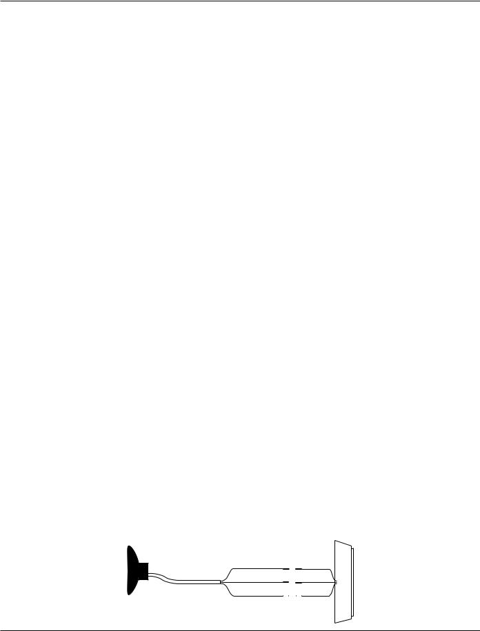
9.Join the meter wires and the HR-RED wires using the connectors from the installation kit, one for each pair of wires.
NNOTE: Polarity must be observed when connecting the meter and the HR-RED wires: red (power/clock) to red, green (data) to green, black (ground) to black.
RED - Power RED
GREEN - Data GREEN
Meter Cable with Flying Leads |
BLACK - Ground |
|
|
BLACK |
|
|
|
|
|
|
|
Page 2 |
DSY-UM-02471-EN-01 |
November 2017 |
 Loading...