


Model PC100 |
Process Controller |
|
|
Installation &
Operation Manual
IMPORTANT !!!! Read this manual before attempting any installation, wiring or operation.
SERVICE INFORMATION
(FILE MANUAL FOR FUTURE REFERENCE AND SERVICE)
Serial Number |
|
Date Installed |
/ |
/ |
||
Service Line |
|
|
Operator |
|
|
|
IOM-036-07
BadgerMeter,Inc. |
Part No. 53400-036 |
3-09
®
2

SCOPE OF THIS MANUAL |
|
OPERATION OF THE PC100 |
The sections in this manual have been arranged in such a way that you can, step-by-step, install, program, operate and, when required, troubleshoot the instrument.
The PC100 has many features. However, for normal operation, you need to be concerned with only a few of them.
The MAIN MENU shows most of the procedures and functions that are normally implemented to properly operate the unit.
The OPTIONAL MENU lists procedures or functions that can be implemented but are not required.
The COMMUNICATIONS MENU should be referenced only if you are connecting the PC100 to a serial printer or to a computer or process controller.
The PC100 is a batch controller. It will accept a signal input from the transmitter, scale it to the desired unit of measure, and send a signal to operate a valve, pump, alarm, motor, etc.
In addition, it can count the number of batches, totalize inventory, indicate rate of flow, provide high and low flow alarms and communicate with printers and computers.
Other features include “slow valve closing” compensation, batch size limit, fail safe shutdown, and programmable function disabling.
After all items of the MAIN MENU have been implemented, select and program those in the OPTIONAL and COMMUNICATIONS MENUS.
MAIN MENU |
|
- Unpack and install the PC100 ................................. |
4 |
- Wiring procedures ................................................... |
4 |
- Assembly and installation of PC100XP .................... |
5 |
- Operation and programming of all functions .......... |
10 |
- Troubleshooting and reprogramming ...................... |
18 |
WIRING |
|
- Connecting pulse transmitters to the PC100 .......... |
6 |
- Connecting single stage valves, two stage valves, |
|
pumps, motors, and alarms ...................................... |
7 |
- Connecting the AC or DC power .............................. |
6 |
PROGRAMMING |
|
- Scale factor to count in gallons, liters, etc. ............ 13 |
|
- Decimal point to show fractions ............................. |
12 |
-Count from zero up or from batch down to zero ..... 12
-End of batch to stay at zero or
to reset to batch size .............................................. |
13 |
- Programming the batch size .................................... |
15 |
- Programming the prewarn or |
|
first valve stage signal ........................................... |
15 |
DISPLAYS |
|
- Ten digit totalizer .................................................... |
10 |
- Instantaneous flow rate ........................................... |
10 |
COMMUNICATIONS MENU |
|
- Wiring a serial printer to the PC100 ....................... |
9 |
- Wiring to host computer or process controller ...... |
9 |
- Wiring the remote Print command .......................... |
9 |
- Selecting communications or totalizer output ...... |
17 |
- Programming the BAUD rate ................................... |
17 |
- Assigning and ID number to each PC100 ............... |
17 |
- Selecting information to be sent to the printer ...... |
17 |
- Selecting automatic print on STOP and/or START .. 17
- Selecting line print delay to match printer used .... |
17 |
- Enabling “on line” message to be printed after |
|
a failure or power down ......................................... |
17 |
OPTIONAL MENU |
|
THE FOLLOWING FUNCTIONS ARE OPTIONAL |
|
TO THE OPERATION OF THE UNIT. |
|
OPTIONAL WIRING |
|
- Connecting remote controls to START, STOP, |
|
RESUME, RESET COUNTERS and PRINT ............. |
8 |
- Connecting a printer ............................................... |
9 |
- Connecting to host computer/process controller .... |
9 |
- Connecting alarms or remote totalizers .................. |
8 |
OPTIONAL PROGRAMMING |
|
- Display FLOW RATE instead of BATCH COUNT ..... |
13 |
- LIMIT the batch size that can be programmed ..... |
15 |
-AUTORECYCLE to repeat batches automatically ... 15
-AUTOADJUST, to compensate for valve overrun .... 15
- CYCLE preset, to stop after a set no. of batches ..... |
15 |
- FAIL-SAFE will stop batch if pulses not sensed ..... |
12 |
- HI and LOW FLOW rate alarm setpoints ................ |
16 |
- FLOW ALARM on/off ................................................ |
16 |
- PREWARN signal duration ...................................... |
15 |
- DISABLE any combination of functions ................. |
14 |
- DISABLE START, STOP, RESUME .......................... |
14 |
- Programming outputs for flow alarms or |
|
scaled pulse output or cycle count output ........... |
12 |
- Resetting the totalizer ............................................ |
16 |
3
HOW TO UNPACK, ASSEMBLE AND INSTALL THE PC100
Note: If damage to the shipping container is obvious, request that the carrier be present when the product is unpacked. All claims for equipment damage during transit are the sole responsibility of the recepient.
UNPACKING
After carefully unpacking the unit, check 

 for any visible sign of damage. If found, notify the carrier for insurance purposes and call the factory for possible replacement. Keep all
packing material in the event that the unit must be return to the factory.
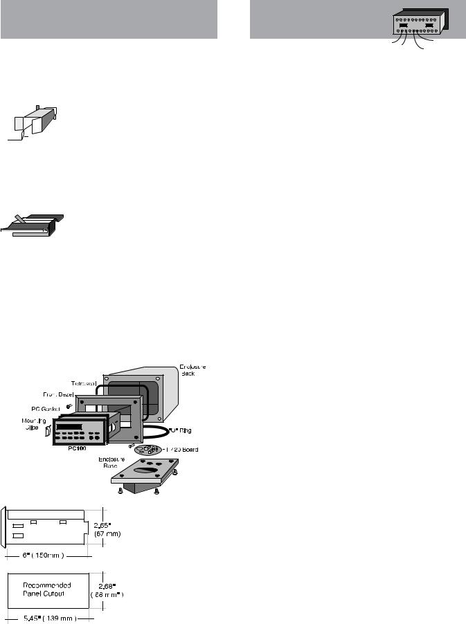
ASSEMBLY
The PC100 can be installed on the flow- 
 meter, on a wall or shelf, or in an instru-
 mentation panel. The picture below shows
  the exploded view of a meter or wall mounted unit. In this configuration, the PC100 is shipped separately and must be installed as shown.
(See wiring diagrams for proper transmitter signal connections.)
The basic unit is equipped for panel mount. To install:
1- Measure and cut mounting hole to the dimensions shown. 2- Install gasket around the mounting bezel.
3- Pass the unit through the front panel cutout.
4- Secure the unit to the panel with the mounting clips. 5- Complete wiring and reassemble unit.
Note: Operating temperature is 32° F to 130° F (0° to 55° C) with a maximum humidity of 85% non-con- densing.
Always select a mounting location with proper ventilation and environment protection.
HOW TO WIRE
THE PC100
The rear panel of the PC100 controller contains 36 screw terminals for connecting #28 to #18 gauge insulated wire (#18 gauge stranded twisted pair shielded cable is recommended.)
A wire stripper and a small screwdriver are the only tools required. Detailed diagrams in this section illustrate the proper wiring procedures for all standard and optional functions.
At installation, be sure to comply with the following requirements:
•Disconnect power to the unit before attempting any connection or service to the unit
•Avoid using machine power service for AC power. When possible, a dedicated or lighting circuit is recommended
•Do not bundle or route signal lines with power lines
•Keep all lines as short as possible
•Use twisted pair shielded wire for all input wiring
•Observe all applicable local electrical codes
Terminal Identification List
No |
Function |
No |
Function |
|
|
|
|
1 |
Reset Cycle Counter |
19 |
DC Power Input |
|
|
|
|
2 |
Resume Remote Input |
20 |
15 VDC Power Output |
3 |
Stop Remote Input |
21 |
DC Common |
|
|
|
|
4 |
Reset Totalizer |
22 |
Relay K1 Contact NC |
5 |
Transistor Output 1 |
23 |
Relay K1 Contact C |
|
|
|
|
6 |
Transistor Output 2 |
24 |
Relay K1 Contact NO |
7 |
Transistor Output 3 |
25 |
AC Power Input |
|
|
|
|
8 |
Transistor Output 1A |
26 |
AC Power Input |
9 |
Transistor Output 2A |
27 |
AC Power Input |
|
|
|
|
10 |
Transmitter Input 2 |
28 |
AC Power Input |
11 |
Low Frequency 2 |
29 |
Relay K2 Contact NC |
|
|
|
|
12 |
DC Common |
30 |
Relay K2 Contact C |
13 |
Low Frequency 1 |
31 |
Relay K2 Contact NO |
|
|
|
|
14 |
Transmitter Input 1 |
32 |
Chassis Ground |
15 |
Function Inhibit |
33 |
Serial Data Input (-) |
|
|
|
|
16 |
Print Command |
34 |
Serial Data Input (+) |
17 |
Start Command |
35 |
Serial Data Output (+) |
|
|
|
|
18 |
Pulse Input Doubler |
36 |
Serial Data Output(-) |
|
|
|
|
CAUTION: To prevent accidents, power connection should
Note: K1 relay coil jumper is factory wired to terminal 8. K2 relay coil jumper is factory wired to terminal 9. At the end of the batch, transistor outputs 2 and 2A (terminals 6 and 9) are energized. At prewarn, terminal outputs 1 and 1A (terminals 5 and 8) are energized.
4

HOW TO ASSEMBLE AND INSTALL THE PC100XP
This section deals with the procedures and recommendations on how to install Badger’s PC100XP electronic batch controller in hazardous locations.
Except for the assembly and installation procedures, all other instructions are identical to the standard PC100 and should be referred to in this manual.
DESCRIPTION
The PC100XP is a standard batch controller mounted in an explosion proof enclosure. The enclosure is FM approved for CLASS 1, DIVISION 1, GROUPS C & D and CLASS II, GROUPS E, F & G environments. The enclosure complys with CSA and UL standards. It is also rated for NEMA 3, 4, 7 & 9 service (watertight).
OPERATION
The operation of the PC100XP is identical to that of the PC100 controller. On the PC100XP model, programming of functions and control commands is done mechanically through explosion proof push buttons.
Note: To prevent accidental or unauthorized tampering, deactivate all programming or command functions (except for those required during production operation) using function #41.
UNPACKING
The PC100XP is shipped from the factory disassembled. The standard PC100 and the XP enclosure are shipped separately to facilitate installation and wiring.
ASSEMBLY
ALWAYS FOLLOW LOCAL CODES AND MANUFACTURER’S INSTRUCTIONS WHEN INSTALLING THIS AND OTHER TYPES OF EQUIPMENT IN HAZARDOUS ENVIRONMENTS.
Note: Operating temperature is 32° F to 130° F with a maximum humidity of 85% non-condensing. Select a mounting location with proper ventilation.
Warning: To prevent the danger of electrical shock or explosion, turn off the power in any circuits that may introduce power to the wiring during the installation of this controller.
STEP-BY-STEP INSTALLATION
The following step-by-step installation instructions should be regarded only as a guideline for proper installation. Local codes or practices may require additional functions to be performed in order to assure safety of installation and operation.
1.Using a 1/4" allen wrench, remove the cover bolts from the front cover. Carefully place the cover over a level surface.
2.Unscrew the mounting plate screws and remove the Mounting plate.
3.Open the PC100 carton and remove the unit. Use the enclosed mounting clips to mount the PC100 to the mounting plate.
4.Using the bottom and/or side tapped holes, mount the XP housing onto a firm platform, cabinet or the wall.
Upon completion of all wiring, tightly close all enclosures within the system.
Before applying power to the system:
•All electrical connections must be secure.
•All seals must be properly poured and completely cured and their seal fittings tightly closed.
•All joints in the conduit run must be tight.
•All enclosures in the system must be tightly closed. Apply power to the controller and test operation in a
manner that is suitable for the particular application. Exercise extreme caution!
For technical assistance during or after installation, please call our sales department or contact the Badger Meter representative in your area.
5

HOW TO CONNECT THE PC100 TO AC OR DC POWER
CAUTION: To prevent accidents, power connection should be made only after all other connections have been completed.
The PC100 is a microprocessor controller. It is important that the power supply be as "clean" as possible. Avoid using power lines that feed heavy loads such as pumps, motors, etc.
If dedicated lines are not available, a filtering or isolation system might be required.
It is recommended that fuse protection be installed. Use a 2/10th amp slow blow fuse on 120 VAC and a 1/10th amp slow blow fuse on 240 VAC supply.
Typical US electrical code identifies the black wire as the hot or hi lead, the white wire as the low or neutral lead, and the green wire as the chassis ground lead.
For 240 VAC operation:
|
|
|
|
|
|
|
|
|
|
USA |
|
|
|
|
|
|
Europe |
|
|
|
|
|
|
|
|
|
|
|
|
|
|
||||||||||||||||||||||
|
|
|
|
|
|
|
|
|
|
Black |
|
|
|
|
|
|
Blue |
|
|
|
|
|
|
|
|
|
|
|
|
|
|
||||||||||||||||||||||
|
|
|
|
|
|
|
|
|
|
Red |
|
|
|
|
|
|
Brown |
|
|
|
|
|
|
|
|
|
|
|
|
|
|
||||||||||||||||||||||
|
|
|
|
|
|
|
|
|
|
Green |
|
|
|
|
|
|
Green/yellow |
|
|
|
|
|
|
|
|
|
|
|
|
|
|
||||||||||||||||||||||
|
|
|
|
|
|
|
|
|
|
|
|
|
|
|
|
|
|
|
|
|
|
|
|
|
|
|
|
|
|
|
|
|
|
|
|
|
|
|
|
|
|
|
|
|
|
|
|
|
|
|
|
|
|
|
|
|
|
|
|
|
|
|
|
|
|
|
|
|
|
|
|
|
|
|
|
|
|
|
|
|
|
|
|
|
|
|
|
|
|
|
|
|
|
|
|
|
|
|
|
|
|
|
|
|
|
|
|
|
|
|
|
|
|
|
|
|
|
|
|
|
|
|
|
|
|
|
|
|
|
|
|
|
|
|
|
|
|
|
|
|
|
|
|
|
|
|
|
|
|
|
|
|
|
|
|
|
|
|
|
|
|
|
|
|
|
|
|
|
|
|
|
|
|
|
|
|
|
|
|
|
|
|
|
|
|
|
|
|
|
|
|
|
|
|
|
|
|
|
|
|
|
|
|
|
|
|
|
|
|
|
|
|
|
|
|
|
|
|
|
|
|
|
|
|
|
|
|
|
|
|
|
|
|
|
|
|
|
|
|
|
|
|
|
|
|
|
|
|
|
|
|
|
|
|
|
|
|
|
|
|
|
|
|
|
|
|
|
|
|
|
|
|
|
|
|
|
|
|
|
|
|
|
|
|
|
|
|
|
|
|
|
|
|
|
|
|
|
|
|
|
|
|
|
|
|
|
|
|
|
|
|
|
|
|
|
|
|
|
|
|
|
|
|
|
|
|
|
|
|
|
|
|
|
|
|
|
|
|
|
|
|
|
|
|
|
|
|
|
|
|
|
|
|
|
|
|
|
|
|
|
|
|
|
|
|
|
|
|
|
|
|
|
|
|
|
|
|
|
|
|
|
|
|
|
|
|
|
|
|
|
|
|
|
|
|
|
|
|
|
|
|
|
|
|
|
|
|
|
|
|
|
|
|
|
|
|
|
|
|
|
|
|
|
|
|
|
|
|
|
|
|
|
|
|
|
|
|
|
|
|
|
|
|
|
|
|
|
|
|
|
|
|
|
|
|
|
|
|
|
|
|
|
|
|
|
|
|
|
|
|
|
|
|
|
|
|
|
|
|
|
|
|
|
|
|
|
|
|
|
|
|
|
|
|
|
|
|
|
|
|
|
|
|
|
|
|
|
|
|
|
|
|
|
|
|
|
|
|
|
|
|
|
|
|
|
|
|
|
|
|
|
|
|
|
|
|
|
|
|
|
|
|
|
|
|
|
|
|
|
|
|
|
|
|
|
|
|
|
|
|
|
|
|
|
|
|
|
|
|
|
|
|
|
|
|
|
|
|
|
|
|
|
|
|
|
|
|
|
|
|
|
|
|
|
|
|
|
|
|
|
|
|
|
|
|
|
|
|
|
|
|
|
|
|
|
|
|
|
|
|
|
|
|
|
|
|
|
|
|
|
|
|
|
|
|
|
|
|
|
|
|
|
|
|
|
|
|
|
|
|
|
|
|
|
|
|
|
|
|
|
|
|
|
|
|
|
|
|
|
|
|
|
|
|
|
|
|
|
|
|
|
|
|
|
|
|
|
|
|
|
|
|
|
|
|
|
|
|
|
|
|
DC supply for mobile operation or as a backup supply can be done with a battery or other DC supply of 11-16 VDC/1amp.
Note: DC supply will not be available from terminal #20 when powering the unit with DC current.
HOW TO CONNECT SIGNAL TRANSMITTERS TO THE PC100
The following diagrams show how to wire most of the flow transmitters supplied with Badger Meter flow meters. Connection of transmitters from other manufacturers is similar. This section deals with pulse outputs generated by reed switches and by current sinking open collector transistors, the most common types of outputs found in flow meter pulse transmitters.
Note: A jumper between terminals #12 and #18 will double the transmitter output frequency.
WARNING!! Transmitter lines carry very low power signals and are sensitive to external noise. Always use shielded cable and keep AC power lines away from signal lines. Do not bundle or route these together since this may cause erratic operation of the PC100. DO NOT ground the cable shield at the transmitter end.
• REED SWITCH TRANSMITTERS (Type A)
Reed switch transmitters close a contact to DC common. Switches of this type have outputs of less than 150 HZ and generate contact bounce.
Therefore, installation of a jumper between terminals #12 and #13 is required. This effectively filters the unwanted extra closures caused by contact bounce. (Jumper terminals #11 and #12 if using transmitter input 2 on terminal #10).
MSE5XP 


• EPT1XP & PEPT1 (TYPE B)
These models require that a special current regulator supplied with the transmitter be installed exactly as shown.
Reversing the polarity will damage the transmitter. No pulses will be detected without it.
EPT-1XP |
6
 Loading...