

Page 1

Model EC-A,
Adjustable
Electric Contacting Register
Installation &
Operation Manual
IOM-425-05
®
BadgerMeter, Inc.
Part No. 53400-425
3-09
Page 2

PREFACE
SCOPE OF THE MANUAL
This manual contains information concerning the installation, operation and maintenance of Badger's Electric
Contracting Register, Model EC-A. To ensure efficient
operation of the EC-A, the instruction given in this
manual should be thoroughly read and understood.
Retain the manual in a location where it is readily
available for reference.
CHANGES IN THE MANUAL
Changes or additions to the original edition of this
manual will be covered by a "CHANGE NOTICE"
supplied with the manual. The change notice will explain any differences between the product received and
the EC-A described in this manual.
the meter causes a cam in the contactor section to
rotate. The cam operates a single-pole, double-throw
switch. When connected to a suitable power supply,
the register will provide a pulse output corresponding to
a predetermined quantity of liquid. If desired, the
pulses can be used to actuate a relay which, in turn, will
operate other equipment. In a typical application,
pulses from the EC-A would be transmitted to a
chemical feed pump for boiler makeup water or for
cooling towers.
SPECIFICATIONS
Totalizer - Nonreset with six number wheels plus
stationary zeros corresponding to test circle.
Units of Measure - Gallons...cubic feet...cubic
meters...liters...pounds.
Switch Type - Single-pole, double-throw...N.O. or N.C.
connections...roller-lever, cam-operated.
Switch Ratings - 10 amps and 1/4 hp, 125 or 250 volts
AC...1/2 amp, 125 volts DC...1/4 amp, 250 volts DC.
Contact Rates - Adjustable in field with change gears
and/or different gear trains.
DESCRIPTION
Badger's Electric Contacting Register, adjustable Model
EC-A, provides an electric pulse output for a given
quantity of liquid passing through a disc, turbo or other
type of meter. The contactor, or lower section of the ECA, contains a gear train assembly, cam-operated rollerlevel switch and appropriate change gears. The top
portion consists of a register with nonreset totalizer and
a hinged cover.
Contact rates can be changed in the field with change
gears and/or one of three different gear trains. To make
sure you obtain the correct parts, contact Badger
Meter, Inc., Customer Service, and provide the following information from EC-A nameplate:
- Existing pulse rate.
- Part number.
- Gear driver/driven.
NOTE: Normally closed contact should be used for
most applications, and especially to obtain shortest
contact duration.
OPERATION
MAINTENANCE AND SERVICING
For periodic inspection or when operation of the EC-A
indicates a need for servicing, refer to adjoining page for
identification of replacement parts and to back cover for
ordering information. If satisfactory servicing cannot be
performed, contact Badger Meter, Inc., Customer Service.
A. CHANGING GEAR TRAIN ASSEMBLY
1. Disconnect electric power at junction box.
2. Loosen and remove two register cover screws
(See item 2 in illustrated parts listed on
facing page.)
3. Lift and remove register hood, gasket and
register assembly (items 1, 4 and 5) from
contactor housing.
DRIVEN
CHANGE
GEAR
DRIVER
CHANGE
GEAR
BOTTOM
PLATE
ASSEMBLY
W/ GEAR TRAIN
ROLLER LEVEL
CAM
GREEN WIRE
(GROUND)
SWITCH
(SPDT)
RED WIRE
BLUE WIRE
BLACK WIRE
The Model EC-A Electric Contacting Register is mounted
on a meter equipped with proper change gears between
meter and register. Water or other liquid flowing through
Figure 2. Electrical Contactor Section
2
Page 3
4. With long-nose pliers, disconnect wire lugs
from terminals on switch (Item 13).
5. With small screwdriver, loosen screw holding ground wire (see Figure 2) and remove
screw and wire lug from bottom plate. Use
hold-down screwdriver to lift out screw.
6. Loosen metal and nylon screws (Items 14 and
17) that anchor bottom plate to housing.
7. The replacement gear train is a complete
assembly with mounting plate (Item 16).
Remove switch from existing plate (see instruction in Switch Replacement section below)
and mount on new assembly.
8. Adjust switch as described in Switch
Replacement section.
9. Install change gears in location as indicated
on nameplate.
B. SWITCH REPLACEMENT
1. To replace switch, remove the entire gear
train assembly as explained in section "A".
2. Remove two screws with hex nuts that hold
switch to bottom plate (Figure 3 on back
page). Install new switch.
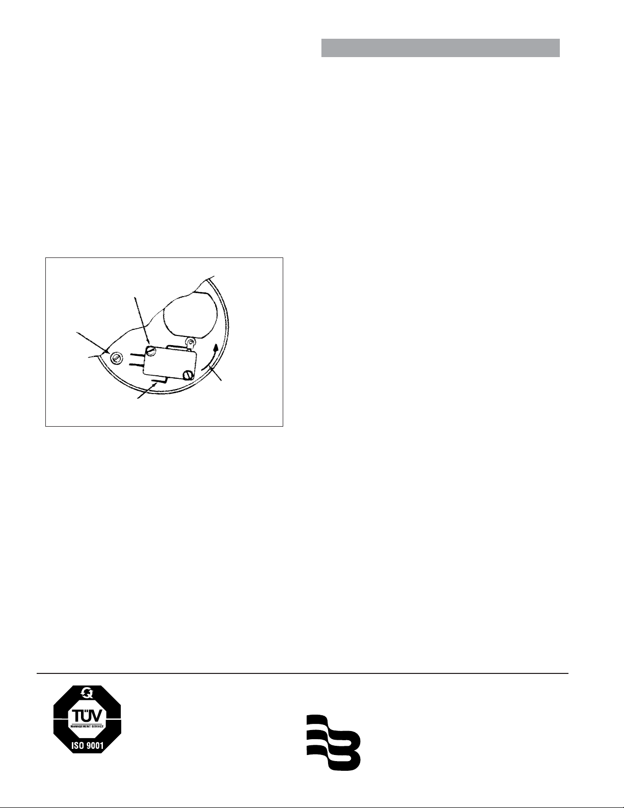
3. With both screws slightly loose, adjust
switch.
4. Rotate cam (Figure 3) so rounded "corner" is
opposite switch.
5. Now rotate switch into cam until normallyopen switch closes.
6. Tighten the screw opposite pivot screw, then
the pivot screw itself.
7. Reinstall gear train assembly in housing.
10. Reassemble contactor assembly, reversing
the procedure outlined above. Make certain
8. Reconnect wires to switch. (See Figure 2 for
proper color coding.)
nylon screw is in mounting hole under switch
lugs.
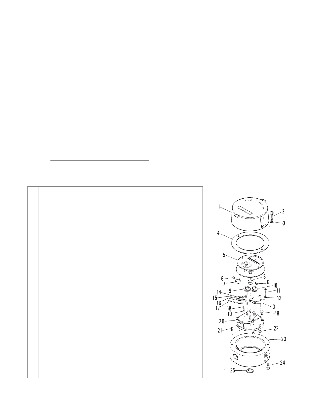
REPAIR PARTS LISTS
Item
No.
1 Hood Assembly, Register………………………………………………… 58234-002
2 Screw, Cover to Housing…………………………………………………. 55048-251
3 Lock Washer……………………………………………………………….. 55293-010
4 Gasket, Register Cover…………………………………………………… 58404-001
5 Register Assembly (Specify meter size and registration required)….. --------------6 Setscrew, Change Gear………………………………………………….. 01065-000
7 Change Gear, Register (Specify number of teeth and diameter)…….. ---------------
Change Gear, Electric Contactor (Specify number of teeth and
8
diameter)……………………………………………………………………
9 Change Gear, Driver (Specify number of teeth and diameter)………… --------------10 Change Gear, Driven (Specify number of teeth and diameter)……….. --------------11 Screw, Pan Head, Switch………………………………………………… 55090-120
12 Lock Washer………………………………………………………………. 55291-005
13 Switch, Roller-Lever……………………………………………………….. 24574-007
14 Wire Lead Assembly, Black (N.C.)……………………………………… 23218-092
15 Wire Lead Assembly, Blue (N.O.)………………………………………. 23218-091
16 Wire Lead Assembly, Red (Common)………………………………….. 23218-090
17 Wire Lead Assembly, Green (Ground)………………………………….. 23218-093
18 Screw, Pan Head, Bottom Plate…………………………………………. 55090-169
19 Lock Washer……………………………………………………………….. 55281-007
20 Bottom Plate and Gear Train Assy. (1:1 Gear Ratio)…………………. 58227-001
20 Bottom Plate and Gear Train Assy. (2:1 Gear Ratio)…………………. 58227-004
20 Bottom Plate and Gear Train Assy. (9:1 Gear Ratio)…………………. 58227-005
21 Screw, Nylon, Bottom Plate……………………………………………… 32296-000
22 Nut, Hex., Bottom Plate………………………………………………….. 55002-032
23 Housing, Contactor………………………………………………………… 57724-002
24 Screw, Fill. Head (Register to housing)…………………………………. 55048-276
Change Gear, Contactor to Meter (Specify number of teeth and
25
diameter)……………………………………………………………………
Name of Part
Part
Number
---------------
---------------
(Instructions continued on back page)
3
Page 4
C. INSTALLING DIFFERENT CHANGE GEARS
1. Repeat steps one through three in Section "A".
2. Loosen setscrews in gear hubs that hold
"driver and "driven" change gears to spindles
(Fig. 2).
3. Lift change gears from spindles.
4. Install different change gears. Note location
so that new gears are installed on correct
spindles (Figure 2).
ORDERING INFORMATION
Order replacement parts through your local Badger
Meter sales representative or directly from Badger
Meter, Inc. When placing an order, provide the following
information:
a. Complete description of assembly or parts
required.
b. Part number of item as listed in illustrated
parts list.
c. Quantity of parts required.
5. Reinstall parts removed under procedure "1"
above. Restore power.
PIVOT
SCREW
NYLON
SCREW
N.C.
N.O.
COMMON
CAM
SWITCH
SWITCH
ADJUSTMENT
MOVEMENT
Figure 3. Switch Adjustment
d. Purchase order number plus exact return and
billing addresses.
Please see our website at
www.badgermeter.com
for specific contacts.
Copyright © Badger Meter, Inc. 2009. All rights reserved.
Due to continuous research, product improvements and enhancements,
Badger Meter reserves the right to change product or system specifications
without notice, except to the extent an outstanding contractual obligation exists.
BadgerMeter, Inc.
P.O. Box 245036, Milwaukee, WI 53224-9536
Telephone: (414) 355-0400 / (800) 456-5023
®
Fax: (414) 355-7499 / (866) 613-9305
www.badgermeter.com
 Loading...