

Page 1

Page 2
Assembly and Use Instruction Manual
Table of Contents
Assembly and Use Instruction Manual ...................................................................................................................... 1
Safety Instruction ..................................................................................................................................................... 2
Parts List ................................................................................................................................................................... 3
Corner Supports & Middle Leg Support Inner Box (Box 1) ....................................................................................... 3
Hardware Box (Box 1) ............................................................................................................................................... 3
Corner Supports & Middle Leg Support Inner Box (Box 1) ....................................................................................... 3
Hardware Box Continued (Box 1) ............................................................................................................................. 4
Box 2 Contents .......................................................................................................................................................... 4
Box 3 Contents .......................................................................................................................................................... 4
Step 1: Ratchet and Rail Holder Installation ............................................................................................................ 5
Step 2: Height Adjustable Leg Assembly .................................................................................................................. 5
Step 3: King Table to Frame Ends ............................................................................................................................. 6
Step 3-C: Crib Table to Frame Ends ........................................................................................................................... 6
Step 4: Corner Brace for King Assembly ................................................................................................................... 7
Step 4-C: Corner Brace for Crib Assembly ................................................................................................................. 7
Step 5: Track Assembly for King Size Frame ............................................................................................................. 8
Step 5-C: Track Assembly for Crib Size Frame .......................................................................................................... 9
Step 6: Front Rail Bracket Assembly ......................................................................................................................... 9
Step 7: Take Up Rail Bracket Assembly ................................................................................................................... 10
Step 8: Bottom Carriage Assembly .......................................................................................................................... 10
Step 9: Track Adjustment ........................................................................................................................................ 11
Step 10: Rail Assembly for King .............................................................................................................................. 12
Step: 10-C: Rail Assembly for Crib .......................................................................................................................... 13
Step 11: Machine Magnetic Bracket ........................................................................................................................ 13
Step 12: Idler Rail Clamp Attachment to Frame ..................................................................................................... 14
Step 13: Rail Attachment to Frame ......................................................................................................................... 15
Step 14: Handwheel Attachment to Rail End .......................................................................................................... 15
Step 15: Leveling Feet Adjustment ......................................................................................................................... 15
Step 16: Wire Connection ........................................................................................................................................ 16
Step 17: Speed Control ............................................................................................................................................ 17
Frame Center Diagram ............................................................................................................................................ 17
Frame Rail Diagram ................................................................................................................................................. 18
Section 1: Fabri-Fast System................................................................................................................................... 18
Section 2: Leader Cloth ........................................................................................................................................... 19
Section 3: Attaching Fabric on the Frame Rails ...................................................................................................... 20
Section 4: Bungee Clamps ....................................................................................................................................... 22
Getting Started ........................................................................................................................................................ 22
Trouble Shooting Guide ........................................................................................................................................... 23
Page. 1
Page 3

Safety Instruction
Read all instructions before using.
When using this machine, basic safety precautions should always be taken, including the following:
FCC Warning Statement
Changes or modications not expressly approved by the party responsible for compliance could void the user’s
authority to operate the equipment.
This equipment has been tested and found to comply with the limits for a Class B digital device, pursuant
to Part 15 of the FCC Rules. These limits are designed to provide reasonable protection against harmful
interference in a residential installation. This equipment generates uses and can radiate radio frequency
energy and, if not installed and used in accordance with the instructions, may cause harmful interference
to radio communications. However, there is no guarantee that interference will not occur in a particular
installation. If this equipment does cause harmful interference to radio or television reception, which can be
determined by turning the equipment off and on, the user is encouraged to try to correct the interference by
one or more of the following measures:
-- Reorient or relocate the receiving antenna.
-- Increase the separation between the equipment and receiver.
-- Connect the equipment into an outlet on a circuit different from that to which the receiver is connected.
-- Consult the dealer or an experienced radio/TV technician for help
WARNING -
Warning: Unplug both power cords from the power outlet when attaching the fabric to your
frame to protect your system from static discharge.
• Never operate this system if it has a damaged cord or plug, if it is not working properly, or if it has been
dropped or damaged. Return the system to the nearest authorized dealer for repair or adjustment.
• Keep ngers away from all moving parts.
• To disconnect, always turn the power button to the off position before unplugging any cables.
• Keep the machine and frame free from the accumulation of lint, dust, and loose cloth.
• Do not unplug by pulling on the cord. To unplug, grasp the plug, not the cord.
If you have any questions contact your authorized Baby Lock retailer.
Page. 2
Page 4
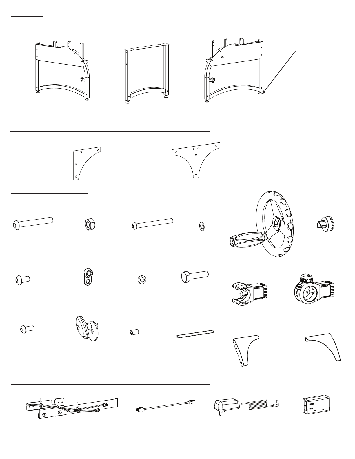
Parts List
Box 1 Contents
Leveling Foot (6)
(Pre-installed on
Frame Ends and
Middle Leg)
03-10943
Left Frame End (1)
A100091
Middle Leg (1)
A100092
Corner Supports & Middle Leg Support Inner Box (Box 1)
Corner Support (2)
04-10708
Middle Leg
Brace (2)
04-10709
Hardware Box (Box 1)
M8 x 50mm
SBHCS (6)
03-10726
M8 Nylock
Nut (6)
03-10730
M10 x 125mm
SBHCS (1)
03-10950
M10 Washer (1)
03-10952
Right Frame End (1)
A100093
Handwheel
Coupler (1)
05-10926
Handwheel Assembly (1)
A100095
M8 x 16mm
SBHCS (36)
03-10951
M6 x 16mm
SBHCS (1)
03-10003
Magnet
Bracket (1)
05-10928
Rail Clamp Lock
Pin Assembly (1)
A100096
Magnet Bracket
Spacer (1)
05-10933
M6 x 8mm Set
Screws (10)
03-10111
1/4 x 1 inch Hex
Bolt (1)
03-10964
Track Coupler (2)
04-10443
Corner Supports & Middle Leg Support Inner Box (Box 1)
Sensor Bracket (1)
A100094
Ethernet Cable
Short (1)
02-10941
Rail Holder
Assembly (1)
A100097
Front Leg
Brace Left (1)
04-10711
Power Supply (2)
02-10940
Top Rail Ratchet
Assembly (1)
A100098
Front Leg
Brace Right (1)
04-10712
Master Board
Box (1)
A100099
Page. 3
Page 5
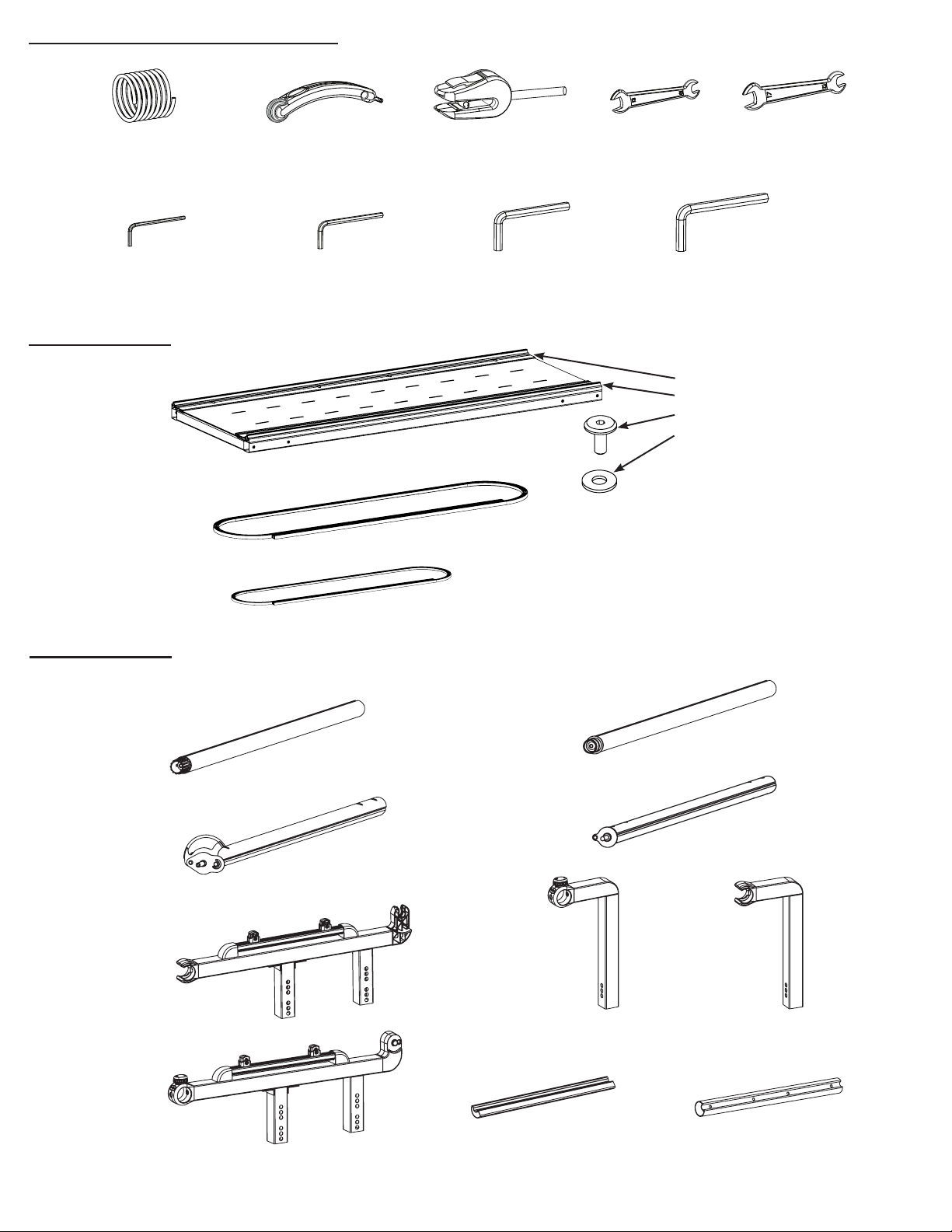
Hardware Box Continued (Box 1)
Fabri-Fast Tubing (4)
05-10439
Box 2 Contents
Table Assembly (2)
A100100
10 ft Plastic Track (4)
05-10330
5 ft Plastic Track (4)
05-10329
3mm Allen
Wrench (1)
03-10166
Fabri-Fast Tool (1)
05-10417
Bungee Clamp (4)
4mm Allen
Wrench (1)
03-10167
08-10572
Open Wrench
13mm and 10mm
03-10743
5mm Allen
Wrench (1)
03-10741
Open Wrench 17mm
and 13mm
03-10948
6mm Allen
Wrench (1)
03-10742
(The following items are preinstalled in Table Assembly)
Rear Track 04-10880
Front Track 04-10878
M6 Connector Bolt 03-10953
M6 Plastic Washer 05-10949
Box 3 Contents
Rail Ratcheting End (4)
A100101
Idler Rail Clamp Locking
Assembly (1)
A100103
Front Rail Bracket Left
Rail Holder End (1)
A100105
Rail Non-Ratcheting End (4)
A100102
Idler Rail Clamp Floating
Assembly (1)
A100104
Take Up Rail Right Arm
Ratchet End (1)
A100108
Take Up Rail Left Arm
Rail Holder End (1)
A100107
Front Rail Bracket
Right Ratchet (1)
A100106
Clamp Rail Coupler (2)
04-10714
Rail Coupler (4)
04-10457
Page. 4
Page 6
Frame Assembly
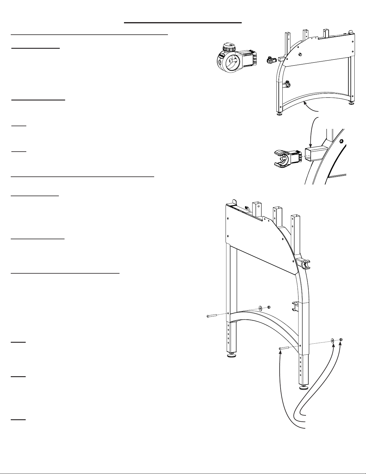
Step 1: Ratchet and Rail Holder Installation
Parts Needed
1- Right Frame End
1- Left Frame End
1- Top Rail Ratchet Assembly
1- Rail Holder Assembly
Tools Required
4mm Allen Wrench
1-1: Insert the Top Rail Ratchet Assembly into the Right Frame End tube end
and tighten the M6 x 25mm SBHCS. (Fig. 1-2)
1-2: Insert and fasten the Rail Holder Assembly into Left Frame End tube
end. (Fig. 1-3)
Top Rail Ratchet
Assembly (Right)
Fig. 1-1
Right Frame End
Left Frame End
Fig. 1-2
Step 2: Height Adjustable Leg Assembly
Parts Needed
1- Right Frame End
1- Left Frame End
1- Middle Leg
Tools Required
5mm Allen Wrench
Open Wrench 13mm and 10mm
Height of Fabric Surface Chart
(Height is determined by the quilting surface to the oor.)
Top Hole 44” 4th 39”
8th 43” 3rd 38”
7th 42” 2nd 37”
6th 41” Bottom Hole 36”
5th 40”
2-1: To adjust the legs, remove the pre-installed M8 x 55mm
SBHCS, M8 Flat Washer, and M8 Nylock Nut from the frame
ends and middle leg if assembling in King size. (Fig. 2-1)
Rail Holder Assembly
(Left)
Fig. 1-3
2-2: Adjust the leg height using the Height of Fabric Surface
Chart. The bottom of the machine handles typically start at
about 8” above the Quilting surface. Determine what setting
will be most comfortable for you based on your height.
2-3: Fasten the M8 x 55mm SBHCS, M8 Flat Washer, and M8
Hex Nut to the adjusted legs with the tools provided. (Fig.
2-1)
Fig. 2-1
M8 Hex Nut
M8 Flat Washer
M8 x 55mm SBHCS
Page. 5
Page 7
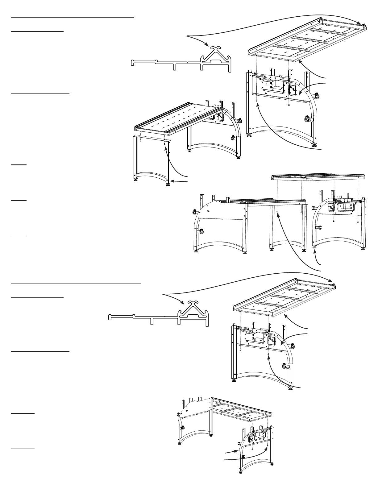
Step 3: King Table to Frame Ends
Parts Needed:
1- Right Frame End
1- Left Frame End
1- Middle Leg
2- Table Assembly
8- M8 x 16mm SBHCS
Tools Required:
5mm Allen Wrench
Note: Using two people is recommended for this step. Loosely fasten
the M8 x 16mm SBHCS to allow for
adjustment in step 4.
3-1: Attach the Table Assembly to
the frame ends using M8 x 16mm
SBHCS. (Fig. 3-1)
Table Assembly Front
Track Prole
Note: The Table Assemblies have
a Pro-Stitcher Compatible Track
which is wider than the rear track.
M8 x 16mm SBHCS
Middle Leg
Fig. 3-1
Table Assembly
Right Frame End
M8 x 16mm SBHCS
3-2: Fasten the Middle Leg to Table
Fig. 3-2
Structure using M8 x 16mm SBHCS.
(Fig. 3-2)
3-3: Bolt the second Table Assembly
to the Middle Leg and Right Frame
End. (Fig. 3-3)
Step 3-C: Crib Table to Frame Ends
Parts Needed:
1- Right Frame End
Table Assembly Front
Track Prole
1- Left Frame End
1- Table Assembly
4- M8 x 16mm SBHCS
Note: The Table Assemblies have
a Pro-Stitcher Compatible Track
which is wider than the rear track.
Tools Required:
5mm Allen Wrench
Fig. 3-3
Left Frame End
M8 x 16mm SBHCS
Table Assembly
Right Frame End
Note: Using two people is recommended for this
step. Loosely fasten the M8 x 16mm SBHCS to
allow for adjustment in step 4-C.
3-1-C: Attach the Table Assembly to the bracket
of the frame ends using M8 x 16mm SBHCS.
(Fig. 3-1-C)
3-2-C: Bolt the other end of the Table Assembly
to the remaining frame end to complete the crib
size frame assembly. (Fig. 3-2-C)
Left Frame End
M8 x 16mm SBHCS
Fig. 3-2-C
Fig. 3-1-C
M8 x 16mm SBHCS
Page. 6
Page 8
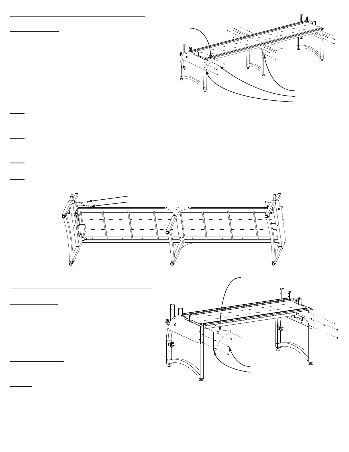
Step 4: Corner Brace for King Assembly
Parts Needed:
Corner Support Long Edge
1- Front Leg Brace Left
1- Front Leg Brace Right
2- Corner Support
2- Middle Leg Brace
26- M8 x 16mm SBHCS
Tools Required:
5mm Allen Wrench
Fig. 4-1
Middle Leg Brace
M8 x 16mm SBHCS
Corner Support
4-1: Align the Corner Supports so that the long edge follows the table surface and fasten with M8 x 16mm
SBHCS. The Corner Supports should lay ush with the Table Assembly and Frame End surfaces. (Fig. 4-1)
4-2: Fasten the Middle Leg Braces to the Table Assemblies and Middle Leg. The Middle Leg Braces should
lay ush with the surface of the Table Assemblies and Middle Leg. (Fig. 4-1)
4-3: Attach the Front Leg Braces to the Table Assemblies and Frame Ends. (Fig. 4-2)
4-4: Securely fasten all the M8 x 16mm SBHCS in this Step and from Step 3.
M8 x 16mm SBHCS
Front Leg Brace Left
Fig. 4-2
Step 4-C: Corner Brace for Crib Assembly
Parts Needed:
1- Front Leg Brace Left
1- Front Leg Brace Right
2- Corner Support
2- Middle Leg Brace
14- M8 x 16mm SBHCS
Tools Required:
5mm Allen Wrench
Corner Support Long Edge
M8 x 16mm SBHCS
Corner Support
4-1-C: Align the Corner Supports so that the
long edge follows the table surface and fasten
with M8 x 16mm SBHCS. The Corner Supports
should lay ush with the Table Assembly and
Frame End surfaces. (Fig. 4-1-C)
Fig. 4-1-C
Page. 7
Page 9

4-2-C: Attach the Front Leg Braces to the Table Assemblies and Frame Ends. (Fig. 4-2-C)
4-3-C: Securely fasten all the M8 x 16mm SBHCS in
this Step and from Step 3-C.
Step 5: Track Assembly for King Size Frame
Parts Needed:
2- Track Coupler
4- 10 ft Plastic Track
8- M6 x 8mm Set Screw
Tools Required:
3mm Allen Wrench
Back Track Support
Front Track Support
4mm Allen Wrench
5-1: Detach the pre-installed Track Support
from the Table Assembly by unfastening the
M6 Connector Bolts with a 4mm Allen Wrench.
(Fig. 5-1)
M8 x 16mm SBHCS
Front Leg Brace Left
Fig. 4-2-C
M6 Connector Bolt
M6 Plastic Washer
5-2: Insert the Track Coupler into the Track
Support end leaving approximately half of the
coupler exposed. (Fig. 5-2) Insert and fasten
M6 x 8mm Set Screws into the Track Support
end using a 3mm Allen Wrench. (Fig. 5-3)
5-3: Slide a Track Support end onto the
coupled back track assembly and fasten M6 x
8mm Set Screws with a 3mm Allen Wrench to
complete one 10 ft Track Support. (Fig. 5-3)
5-4: Slide the 10 ft Plastic Track down the
track groves of the Back Track Support Assembly. (Fig. 5-4)
5-5: Repeat step 5-2 to 5-4 to assemble the
10 ft Front Track Support Assembly.
5-6: Loosely fasten the Front Track Assembly
and securely fasten the Rear Track Assembly
onto the Table Assembly with Connector Bolts
and M6 Plastic Washers. The Rear Track As-
sembly side should be ush with the back edge
of the table. (Fig. 5-1)
Fig. 5-1
Fig. 5-2
Fig. 5-3
Back Track Support
Track Coupler
M6 x 8mm Set Screw
Note: The Front Track Assembly will be adjusted and tightened in step 9.
Fig. 5-4
Rear Track Assembly Side
Plastic Track
Page. 8
Page 10

Step 5-C: Track Assembly for Crib Size Frame
Parts Needed:
Back Track Support
Front Track Support
4- 5 ft Plastic Track
Tools Required:
4mm Allen Wrench
5-1-C: Detach the pre-installed Track Support
from the Table Assembly by unfastening the
M6 Connector Bolts with a 4mm Allen Wrench.
(Fig. 5-1-C)
5-2-C: Slide the 5 ft Plastic Track down the
track grooves of the Track Support Assembly.
(Fig. 5-2-C)
5-3-C: Repeat step 5-2 to assemble the 5 ft
Front Track Support Assembly.
5-4-C: Loosely fasten the Front Track Assembly and securely fasten the Back Track Assembly onto the Table Assembly with Connector
Bolts and M6 Plastic Washer. The Rear Track
Assembly side should be ush with the back
edge of the table. (Fig. 5-1)
Fig. 5-1-C
Fig. 5-2-C
M6 Connector Bolt
M6 Plastic Washer
Back Track Assembly Side
Plastic Track
Note: The Front Track Assembly will be adjusted and tightened in step 9.
Front Rail Bracket Left Rail Holder
End
Step 6: Front Rail Bracket Assembly
Parts Needed:
1- Front Rail Bracket Right Ratchet End
1- Front Rail Bracket Left Rail Holder End
Fig. 6-1
Note: Loosen the M8 x 16mm SBHCS on the Rail Brackets if the brackets are a tight t into frame ends.
4- M8 x 50mm SBHCS
4- M8 Nylock Nut
Tools Required:
5mm Allen Wrench
Open Wrench 13mm and 10mm
Note: The bolt height may need to be adjusted after the
sewing machine has been set on the frame so that fabric
lays at in the throat of the machine. This assembly step
is universal for both Crib and King size frames.
6-1: Insert the Rail Brackets into the corresponding tube
ends. (Fig. 6-2)
M8 x 16mm SBHCS
Front Rail Bracket Left Rail Holder End
Front Rail Bracket Right Ratchet End
Rail Holding End
M8 Nylock Nut
M8 x 50mm SBHCS
Ratchet End
Fig. 6-2
Page. 9
Page 11

6-2: Fasten a set of M8 x 50mm SBHCS and M8 Nylock
Nuts through the second hole from the bottom of the Rail
Brackets as a default. (Fig. 6-2 and Fig. 6-3)
M8 Nylock Nut
M8 x 50mm SBHCS
Step 7: Take Up Rail Bracket Assembly
Parts Needed:
1- Take Up Rail Right Arm Ratchet End
1- Take Up Rail Left Arm Rail Holder End
2- M8 x 50mm SBHCS
2- M8 Nylock Nut
Tools Required:
5mm Allen Wrench
Open Wrench 13mm and 10mm
Fig. 6-3
Take Up Rail Left Arm Rail Holder End
Take Up Rail Right Arm Ratchet End
Note: The height may need to be adjusted after
the sewing machine has been set on the frame.
This assembly step is universal for both Crib and
King size frames.
7-1: Insert the Rail Brackets into the corresponding
tube ends. (Fig. 7-1)
7-2: Fasten a set of M8 x 50mm SBHCS and M8
Nylock Nuts through the middle hole of the Rail Arm
Brackets. (Fig. 7-1)
Step 8: Bottom Carriage Assembly
Parts Needed:
2- M6 Set Screw
1- Sensor Bracket
1- Carriage Assembly (included
with sewing machine)
1- Master Board Box
1- Power Supply
Fig. 8-1
Non-Ratchet End
Fig. 7-1
Ratchet End
Backside of
the carriage
Sensor
Bracket tab
Tools Required:
3mm Allen Wrench
8-1: Attach and align the Sensor Bracket to the
backside of the carriage. The Sensor Bracket tab
should be ush against the rear of the carriage.
(Fig. 8-1)
8-2: Insert and fasten a set of M6 Set Screws
into the Sensor Bracket. (Fig. 8-2)
Fig. 8-2
M6 Set Screw
Page. 10
Page 12

8-3: Position the Master Board Box so that the
two ports are facing the front of the carriage.
Peel the tape from the back of the Master Board
Box and attach the box to the side of the Carriage Assembly. (Fig. 8-3)
8-4: Plug the Front Cable into the Front Port
and Rear Cable into the Rear Port on the Master
Board Box. (Fig. 8-4)
Step 9: Track Adjustment
Parts Needed:
1- Bottom Carriage Assembly
1- Frame Assembly
Tools Required:
4mm Allen Wrench
Fig. 8-3
Fig. 8-4
Front Cable
Rear Cable
Master Board Box
Front
Rear
Note: This assembly step is universal for both
Crib and King size frames.
9-1: Place and align the Bottom Carriage Assembly on the track assemblies. The Front Track
Assembly should be loosely fastened from a
previous step. (Fig. 9-1)
9-2: The Rear Track Support should be aligned
ush with the Table Frame Side from a previous
step. If not, align and securely fasten. (Fig. 9-1)
9-3: Press down on the Bottom Carriage As-
sembly and move the carriage from left to right,
fastening the Front Track M6 Connector Bolts
rmly. Continue this step for the remainder of
the Connector Bolts along the frame. (Fig. 9-2)
Fig. 9-1
Fig. 9-2
Rear Track Side
Rear Frame Side
M6 Connector Bolts
Page. 11
Page 13

Step 10: Rail Assembly for King
Parts Needed:
4- Rail Ratcheting End
4- Rail Non-Ratcheting End
4- Rail Coupler
2- Clamp Rail Coupler
1- Idler Rail Clamp Locking
Assembly
1- Idler Clamp Floating Assembly
24 - M6 x 10mm Set Screws (Pre-
installed in the Rail Couplers)
Tools Required:
3mm Allen Wrench
Note: Loosen M6 x 10mm Set Screws if the
Rail Couplers do not easily slide into the rail
ends. (Fig. 10-1)
10-1: Insert a Rail Coupler into a Rail Ratcheting End. Align the holes on the Rail Coupler
with the holes in the rail ends. (Fig. 10-2 and
Fig. 10-3.)
10-2: Tighten the pre-installed M6 x 10mm
Set Screws in the ratcheting and Non-Ratchet-
ing rail ends with an 3mm Allen Wrench. (Fig.
10-4)
Fig. 10-1
End
Fig. 10-2
Fig. 10-3
Fig. 10-4
Idler Rail Clamp
Locking Assembly
Fig. 10-5
3mm Allen Wrench
Rail Ratcheting EndRail Non-Ratcheting
Rail Coupler
Idler Clamp Floating
Assembly
Clamp Rail Coupler
10-3: Repeat step 10-1 and 10-2 for the
three remaining Rail Assemblies.
10-5: Insert the Clamp Rail Couplers into an
Idler Clamp Floating Assembly End. Align the
holes on the Clamp Rail Couplers with the
holes in the rail ends. (Fig. 10-5 and Fig. 10-
6.) Align the Clamp Rails so that the hinges
are on the same side. (Fig. 10-7)
10-6: Tighten the pre-installed M6 x 10mm
Set Screws into the Idler Rail Clamp Locking
Assembly and Idler Clamp Floating Assembly
with an 3mm Allen Wrench. (Fig. 10-7)
Fig. 10-6
Fig. 10-7
Hinges
Page. 12
Page 14

Step: 10-C: Rail Assembly for Crib
Parts Needed:
4- Rail Ratcheting End
4- Rail Non-Ratcheting End
Fig. 10-1-C
Rail Ratcheting End
Non-Ratcheting End Insert
1- Idler Rail Clamp Locking
Assembly
1- Idler Clamp Floating Assembly
Hinge
Hinge
8 - M6 x 10mm Set Screws (Pre-
installed in the Rail Couplers)
Tools Required:
3mm Allen Wrench
4mm Allen Wrench
6mm Allen Wrench
Fig. 10-2-C
Idler Rail Clamp Locking Assembly
Idler Clamp Floating Insert
M6 Set Screws
10-1-C: Unfasten the Non-Ratcheting End Insert from a Rail Non-Ratcheting End with a 6mm Allen Wrench.
Insert and fasten the Non-Ratcheting End Insert into the Rail Ratcheting End. (Fig. 10-1-C)
Note: If the rail end is difcult to remove, loosen the bolt half way out. Push in the bolt to release the compression cone, which will allow the rail end to be easily removed.
10-2-C: Repeat step 10-1-C for the remaining 3 rail ends.
10-3-C: Unfasten the Idler Clamp Floating Insert from the Idler Clamp Floating Assembly by removing four
M6 Set Screws with an M3 Allen Wrench. Insert and Fasten the Idler Clamp Floating Insert into the Idler Rail
Clamp Locking Assembly. Align the Clamp Rails so that the hinges are on the same side. (Fig. 10-2-C)
Step 11: Machine Magnetic Bracket
Parts Needed:
1- Magnet Bracket
1- Magnet Bracket Spacer
1- 1/4 x 1 inch Hex Bolt
Tools Required:
Fig. 11-1
1- 7/16 inch Wrench (Not provided with frame
contents.)
Magnet Bracket Spacer
Magnet Bracket
1/4 inch Hex Bolt
11-1: Remove the 1/4 x 1 inch hex bolt from the rear
right machine wheel. Align and fasten the Magnet
Bracket Spacer, Magnet Bracket, and 1/4 x 1 inch Hex
Bolt. (Fig. 11-1)
11-2: Place the Machine on the Bottom Carriage. (Fig.
9-3)
Note: Magnet Bracket Spacer is not used when using a
Pro-Stitcher system. This assembly step is universal for
both Crib and King size frames.
Fig. 11-2
Page. 13
Page 15

Step 12: Idler Rail Clamp Attachment to Frame
Parts Needed:
1- Idler Rail Assembly
1- Rail Clamp Lock Pin Assembly
1- M6 x 16mm SBHCS
Tools Required:
4mm Allen Wrench
Foward
Note: This assembly step is universal for
both Crib and King size frames.
Idler Rail Assembly clamp locking end
Front Rail Bracket Ratchet End rear hole
12-1: Insert the Idler Rail Assembly
through the throat of the machine and
clamp locking end into the Front Rail
Bracket Ratchet End rear hole. (Fig. 12-1)
Fig. 12-1
12-2: Rotate the Idler Rail Assembly so
that the Clamp Lock Rail End square Key is
facing forward. (Fig. 12-2)
12-3: Clip the Non-Ratcheting Floating
Clamp Lock Rail End Key
End into Front Rail Bracket Non-Ratchet
rear coupler. (Fig. 12-3)
Fig. 12-2
12-4: Align the keyed ends of the Idler Rail Assembly clamp locking end with the Rail Clamp Lock Pin end.
Attach the Rail Clamp Lock Pin Assembly to the Idler Rail Clamp Locking Assembly by fastening the M6 x
16mm SBHCS with a 4mm Allen Wrench. (Fig. 12-4)
Fig. 12-3
Front Rail Bracket Non-Ratchet rear coupler
Rail Clamp Lock Pin Assembly
M6 x 16mm SBHCS
Idler Rail Assembly clamp locking end key
Rail Clamp Lock Pin end key
Fig. 12-4
Page. 14
Page 16

Step 13: Rail Attachment to Frame
Parts Needed:
4- Rail Assembly
Note: This assembly step is universal for
both Crib and King size frames.
13-1: Insert the Rail Assembly through
the throat of the machine and Ratcheting
End into the Rail Ratchet End of the take
up rail ratchet assembly. (Fig. 13-1)
13-2: Clip the Non-Racheting End of the
rail into the Rail Holder of the take up rail
non-ratchet assembly. (Fig. 13-1)
13-3: Similar to Steps 13-1 and 13-2
install the remaining rails into their corresponding frame ends. (Fig. 13-1)
Fig. 13-1
Non-Ratcheting End
Rail Holder
Rail Ratchet End
Ratching End
Step 14: Handwheel Attachment to Rail End
Parts Needed:
1- Handwheel Assembly
1- Handwheel Coupler
1- M10 Washer
1- M10 x 125mm SBHCS
Tools Required:
6mm Allen Wrench
Note: This assembly step is universal for both
Crib and King size frames.
14-1: Remove the M10 x 80mm SBHCS from
the existing Take Up Rail Assembly with a 6mm
Allen Wrench. (Fig. 14-1)
14-2: Fasten Handwheel Coupler, Handwheel
Assembly, M10 Washer, and M10 x 125mm
SBHCS with a 6mm Allen Wrench to the end of
the Rail Assembly from Step: 14-1. (Fig. 14-2)
M10 x 80mm SBHCS
Fig. 14-1
M10 x 125mm SBHCS
M10 Washer
Handwheel Assembly
Handwheel Coupler
Fig. 14-2
Step 15: Leveling Feet Adjustment
Tools Required:
1- Open Wrench 17mm
Step 15-1: Adjust leveling feet with the 17mm Open Wrench so
that the machine remains stationary without interaction from the
user. To raise the leg of the machine simply turn the foot clock-wise
shown in Fig. 15-1 and reverse action to lower the foot.
Fig. 15-1
Page. 15
Page 17

Step 16: Wire Connection
Parts Needed:
1- Ethernet Cable Short
2- Ethernet Cable Long (Pre-installed on frame
ends)
1- Power Supply
2- Motor Cable (Pre-installed on frame ends)
16-1: Plug the Ethernet Cable Short into the Ethernet
ports on the underside of the Table Assemblies between
the Middle Leg. (Fig. 16-1)
Note: Step 16-1 is only required for King size frame as-
sembly.
16-2: Plug the Ethernet Cable Long, Power Supply Cable, and Motor Cable into the corresponding ports in the
Right Frame End. The Motor Cable Tab must be oriented
upward. (Fig. 16-2 and Fig. 16-3)
16-3: Plug the Ethernet Cable Long and Motor Cable into
the corresponding ports on the Left Frame End.
Note: The Left Frame End does not require a power supply.
16-4: Plug the Ethernet Cables that are near the rear of
the Frame Ends into the Table Assembly Ethernet Port.
(Fig. 16-4 and Fig. 16-5)
Fig. 16-1
Motor Cable
Tab
Fig. 16-2
Ethernet Cable Short
Middle Leg
Right Frame
End
Ethernet Cable Long
Power Supply Cable
Motor Cable
16-5: Plug the Power Supply into the Master Board Box.
(Fig. 16-6)
Fig. 16-3
Ethernet Port
Ethernet Cable
Fig. 16-4
Fig. 16-5
Right Frame
End
Master Board Box
Power Supply
Fig. 16-6
Page. 16
Page 18

16-6: Plug a 12V power supply into the sewing machine board on the carriage and into 110 – 220 VAC
power.
Step 17: Speed Control
Note: The Speed Control knob is located
on the side of the Right Frame End.
17-1: Switching the Speed Control Knob
setting away from STOP turns the sliding
rail on and controls the speed at which the
sliding rails move. (Fig. 16-1)
Frame Center Diagram
Crib Center 30 in
Fig. 17-1
King Center 60 in
King Total Length 120 in
Page. 17
Page 19

Frame Rail Diagram
Quilting Setup
Take up Rail
Idler Rail
Backing Rail
Top Rail
Batting Rail
Section 1: Fabri-Fast System
Tools Required:
1- Fabri-Fast Tool
4- Fabri-Fast Tube
Fig-S. 1-1
Fabri-Fast Tool
Fabri-Fast Tube
Note: This assembly step is universal for both Crib and King size frames.
Section 1-1: Lay the fabric over the Fabri-Fast Slot of a rail assembly and secure the fabric by pressing in
the Fabri-Fast Tubing with a Fabri-Fast Tool. (Fig. 1-1-S)
Note: Some fabrics maybe difcult to insert into the Fabri-Fast Slot, another option is to tape the fabric to
the rail.
Page. 18
Page 20

Section 2: Leader Cloth
Leader Cloth Diagram
Section 2-1: High thread count fabric such as Muslin is recommended for
18"
3/4" Casing
Top Leader
Leader Cloth material. Thick fabric may
be difcult to install in the rail Fabri-Fast
Slot.
18"
3/4" Casing
Backing Leader
Section 2-2: Cut your Leader Cloth
fabric to the match that of the Leader
Cloth Diagram with room for 1 inch for
a fabric casing and the width 6 inches
shorter than your rail length. Surge or
24"
3/4" Casing
Take-up Leader
Center Marks
hem all edges.
Fig-S. 2-1
Section 2-3: Fold over 1 inch for the fabric casing and sew a 3/4 inch casing with a conventional
sewing machine leaving both ends open.
Section 2-4: Slide the Fabri-Fast Tubing down the casing to ease the use of the Fabri-Fast system.
(Section 1)
Section 2-5: Pin the Leader Cloths to the appropriate sections of the quilt. (Fig-S. 2-2)
Leader Cloth Example
Casing
Take Up Leader
Insert Fabri-Fast Tube
Down the Length of
Casing
Fig-S. 2-2
Pins
Casing
Top Leader
Quilt Top
Batting
Quilt Backing
Backing Leader
Casing
Page. 19
Page 21

Section 3: Attaching Fabric on the Frame Rails
Tools Required:
1- Fabri-Fast Tool
4- Fabri-Fast Tube (Crib or King)
Note: This assembly step is universal for both Crib
and King size frames.
Section 3-1: Move the sewing machine back so that
the Take Up Rail moves to the rear position. (Fig-
S. 3-1) Unplug the power cords so the Take Up Rail
stays in the rear position.
Section 3-2: Pull the Rail Clamp Clip out and twist
the Idler Rail Clamp open. (Fig-S. 3-2)
Section 3-3: Attach the Take Up Leader into the
Take Up Rail using the Fabri-Fast System. (Fig-S. 3-3)
Section 3-4: Feed the Take Up Leader through the
Idler Rail hinged slot. (Fig-S. 3-3)
Take up Rail
Fig-S. 3-1
Take up Rail
Section 3-5: Pin the fabric and the batting to the
Take Up Leader. (Section 2: Leader Cloth and Fig-S.
3-3)
Section 3-6: Clamp the fabric by latching the Rail
Clamp Clip. (Fig-S. 3-3 and Fig-S. 3-4)
Take up Rail
Rail Clamp
Clip
Take Up Leader
Fig-S. 3-2
Take up Rail
Idler Rail
Rail Clamp
Clip
Idler Rail
Rail Clamp Clip
Fig-S. 3-3
Batting
Fabric
Idler Rail
Take Up Leader
Fig-S. 3-4
Page. 20
Page 22

Section 3-7: Disengage the Clamp Rail Lock Pin and
tighten the Idler Rail Assembly by turning the rail Counterclockwise a full rotation. Re-engage the Clamp Rail
Lock Pin ensuring the fabric is wrapped on the Idler Rail.
(Fig-S. 3-5)
Note: Section 3-7 will make the Quilting Surface at
and taut during quilting while the sliding rail operates.
Sections: 3-2, 3-6, and 3-7 will have to be repeated as
the quilt is rolled up on the Take Up Rail.
Section 3-6: Attach the Backing Leader to the Backing
Rail using the Fabri-Fast System and ratchet the remaining fabric onto the rail. (Section 1: Fabri-Fast System
and Fig-S. 3-7)
Section 3-7: Similarly, attach the Top Leader to the Top
Rail using the Fabri-Fast System and ratchet the remaining fabric onto the rail. (Section 1: Fabri-Fast System
and Fig-S. 3-8)
Take Up Leader
Fig-S. 3-5
Clamp Rail Lock
Pin
Section 3-8: The batting can be Fabri-Fasted onto the
Batting Rail if the batting is thin, otherwise tape and roll
it onto the rail to ease batting management. (Fig-S. 3-8)
Note: The Take Up Rail and Batting Rail have no par-
ticular direction of rotation and can rotate both ways
without effecting the frames performance.
Plug the power cords back in after the fabric installation
has been completed.
Top Leader
Quilt Top
Batting
Quilt Backing
Fig-S. 3-6
Quilt Top
Batting
Backing Rail
Fig-S. 3-7
Top Rail
Batting Rail
Fig-S. 3-8
Page. 21
Page 23

Section 4: Bungee Clamps
Tools Required:
4- Bungee Clamp
Note: This assembly step is universal for
both Crib and King size frames.
Section 4-1: Depress the bungee stop that
is built into the Bungee Track System and
pass the end of the bungee cord through the
bungee stop hole. (Fig-S. 4-1)
Section 4-2: Clamp the Bungee to the edge
of the fabric. Depress the bungee stop while
pulling on the cord end for tension and release when taut to lock. (Fig-S. 4-1)
Getting Started
Press to Unlock
Bungee Clamp
Fig-S. 4-1
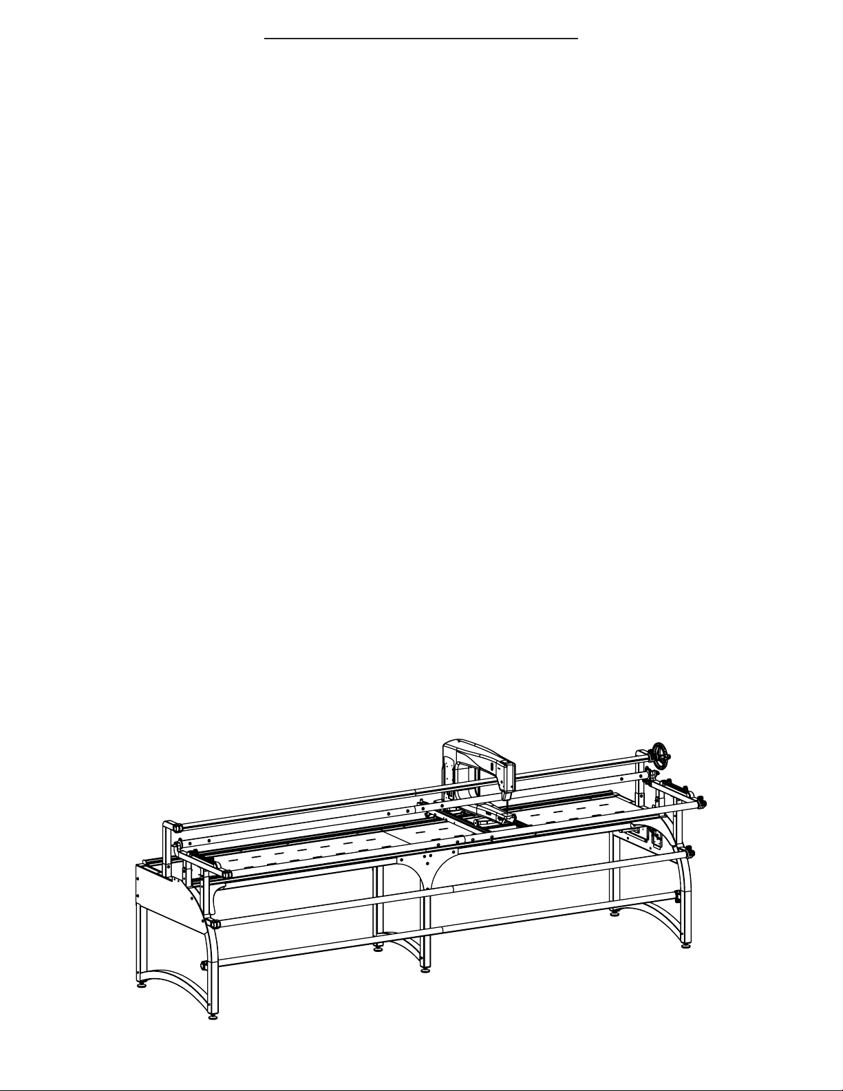
The Momentum Frame is a unique patented system that allows the user to quilt the same size patterns all
the way through the quilt unlike traditional quilting frames. As a quilt is rolled onto the Take Up Rail through
the quilting process, the Momentum Frame automatically moves the completed portion of the quilt that is
rolled onto the Take Up Rail forward and back to permit the user take advantage of the entire length of the
throat of the machine. For the rst time ever, the maximum pattern size possible for the sewing machine
can be quilted from the beginning to end of a quilt without having to plan or compensate for the increasing
size of the fabric roll on the take up rail.
Upon completing the assembly of the frame, plug in the power supply from the Master Control Box and the
from the Right Frame End. The system is designed for use with 110-220 AVC power. Using a power strip or
surge protector will protect your system from power surges. The red LED light on the Master Control Board
and Right Frame Side indicates the system has power. The blue LED light indicates communication between
the circuit boards.
To use the system, set the control knob on the right side of the frame to Fast. Move the sewing machine forward and back on the carriage ve or six times to calibrate the system. The Take Up Rail Assembly will move
away from the needle as you move the machine back and away from the back of the throat of the machine
as you move the machine forward. During calibration the initial rst few movements of each side of the
frame may not be immediately even until calibration is complete. The system will gradually calibrate with
each movement causing the two sides to increasingly move more and more evenly. Each time the frame is
powered on or the speed setting is changed, it will begin the calibration process. After the initial ve or six
movements, the system will be calibrated and is ready for quilting.
Page. 22
Page 24

Trouble Shooting Guide
Sliding Rail not moving: Check if the Speed Control Knob is switched away from stop. The cables to the
Master Board Box, Frame Ends, and Table Structure must be attached correctly in their respective ports.
(Step 8: Bottom Carriage Assembly, Step 15: Wire Connection, and Step 16: Speed Control) There is also a
built-in sleep mode when the machine is not in operation. This may need to be reset, which would require
the user to unplug and plug the AC Power Supply.
Bungee Clamps: If it is necessary to use the bungee clamps over the batting on your quilt, turn the bun-
gee clamps upside down so the rubber grip in the clamp is gripping against the bottom fabric instead of the
batting. Having the rubber grip clamp against the batting is less effective than having it clamp against the
fabric.
Fabric Issues: Do not over-tighten the fabric on the quilting frame. Stretching the fabric will result in a
quilt that does lay at when it is nished.
Frame Cleaning: Regularly clean the wheels and track of your carriage and frame. Lint from the batting
will build up quickly, causing the carriage not to roll as smoothly if neglected.
Page. 23
 Loading...