

Page 1

Page 2

TRADEMARKS
IMPORTANT:
READ BEFORE DOWNLOADING, COPYING, INSTALLING OR USING.
By downloading, copying, installing or using the software you agree to this license. If you do not agree
to this license, do not download, install, copy or use the software.
Intel License Agreement For Open Source Computer Vision Library
Copyright © 2000, Intel Corporation, all rights reserved. Third party copyrights are property of their respective owners.
Redistribution and use in source and binary forms, with or without modification, are permitted provided that the
following conditions are met:
• Redistribution’s of source code must retain the above copyright notice, this list of conditions and the following
disclaimer.
• Redistribution’s in binary form must reproduce the above copyright notice, this list of conditions and the
following disclaimer in the documentation and/or other materials provided with the distribution.
• The name of Intel Corporation may not be used to endorse or promote products derived from this software
without specific prior written permission.
This software is provided by the copyright holders and contributors “as is” and any express or implied warranties,
including, but not limited to, the implied warranties of merchantability and fitness for a particular purpose are
disclaimed. In no event shall Intel or contributors be liable for any direct, indirect, incidental, special, exemplary,
or consequential damages (including, but not limited to, procurement of substitute goods or services; loss of use,
data, or profits; or business interruption) however caused and on any theory of liability, whether in contract, strict
liability, or tort (including negligence or otherwise) arising in any way out of the use of this software, even if
advised of the possibility of such damage.
All information provided related to future Intel products and plans is preliminary and subject to change at any time, without notice.
SD is a registered trademark or a trademark of SD-3C, LLC.
CompactFlash is a registered trademark or a trademark of Sandisk Corporation.
Memory Stick is a registered trademark or a trademark of Sony Corporation.
SmartMedia is a registered trademark or a trademark of Toshiba Corporation.
MultiMediaCard (MMC) is a registered trademark or a trademark of Infineon Technologies AG.
xD-Picture Card is a registered trademark or a trademark of Fuji Photo Film Co. Ltd.
IBM is a registered trademark or a trademark of International Business Machines Corporation.
Microsoft, Windows and Windows Vista are registered trademarks or trademarks of Microsoft Corporation.
Each company whose software title is mentioned in this manual has a Software License Agreement specific to its proprietary programs.
All other brands and product names mentioned in this manual are registered trademarks of their respective companies. However, the
explanations for markings such as
® and ™ are not clearly described within the text.
Page 3

INTRODUCTION
INTRODUCTION
Thank you for purchasing this machine. Before using this machine, carefully read the “IMPORTANT
SAFETY INSTRUCTIONS”, and then study this manual for the correct operation of the various functions.
In addition, after you have finished reading this manual, store it where it can quickly be accessed for
future reference.
IMPORTANT SAFETY INSTRUCTIONS
Please read these safety instructions before attempting to use the machine.
DANGER - To reduce the risk of electrical shock
1Always unplug the machine from the electrical outlet immediately after using, when cleaning, making any user
servicing adjustments mentioned in this manual, or if you are leaving the machine unattended.
WARNING - To reduce the risk of burns, fire, electrical shock, or injury to
persons.
2Always unplug the machine from the electrical outlet when making any adjustments mentioned in the instruction
manual.
• To unplug the machine, switch the machine to the symbol “O” position to turn it off, then grasp the plug and pull
it out of the electrical outlet. Do not pull on the cord.
• Plug the machine directly into the electrical outlet. Do not use an extension cord.
• Always unplug your machine if the power is cut.
3Electrical Hazards:
• This machine should be connected to an AC power source within the range indicated on the rating label. Do not
connect it to a DC power source or inverter. If you are not sure what kind of power source you have, contact a
qualified electrician.
• This machine is approved for use in the country of purchase only.
4Never operate this machine if it has a damaged cord or plug, if it is not working properly, has been dropped or
damaged, or water is spilled on the unit. Return the machine to the nearest authorized retailer for examination,
repair, electrical or mechanical adjustment.
• While the machine is stored or in use if you notice anything unusual, such as an odor, heat, discoloration or
deformation, stop using the machine immediately and unplug the power cord.
• When transporting the machine, be sure to carry it by its handle. Lifting the machine by any other part may
damage the machine or result in the machine falling, which could cause injuries.
• When lifting the machine, be careful not to make any sudden or careless movements, otherwise you may injure
your back or knees.
B-1
Page 4

IMPORTANT SAFETY INSTRUCTIONS
5Always keep your work area clear:
• Never operate the machine with any air openings blocked. Keep ventilation openings of the machine and foot
control free from the build up of lint, dust, and loose cloth.
• Do not use extension cords. Plug the machine directly into the electrical outlet.
• Never drop or insert foreign objects in any opening.
• Do not operate where aerosol (spray) products are being used or where oxygen is being administered.
• Do not use the machine near a heat source, such as a stove or iron; otherwise, the machine, power cord or
garment being sewn may ignite, resulting in fire or an electric shock.
• Do not place this machine on an unstable surface, such as an unsteady or slanted table, otherwise the machine
may fall, resulting in injuries.
6Special care is required when embroidering:
• Always pay close attention to the needle. Do not use bent or damaged needles.
• Keep fingers away from all moving parts. Special care is required around the machine needle.
• Switch the machine to the symbol “O” position to turn it off when making any adjustments in the needle area.
• Do not use a damaged or incorrect needle plate, as it could cause the needle to break.
• Do not push or pull the fabric when embroidering.
7This machine is not a toy:
• Your close attention is necessary when the machine is used by or near children.
• The plastic bag that this machine was supplied in should be kept out of the reach of children or disposed of.
Never allow children to play with the bag due to the danger of suffocation.
• Do not use outdoors.
8For a longer service life:
• When storing this machine, avoid direct sunlight and high humidity locations. Do not use or store the machine
near a space heater, iron, halogen lamp, or other hot objects.
• Use only neutral soaps or detergents to clean the case. Benzene, thinner, and scouring powders can damage the
case and machine, and should never be used.
• Always consult the operation manual when replacing or installing any assemblies, the presser feet, needle, or
other parts to assure correct installation.
9For repair or adjustment:
• If the light unit is damaged, it must be replaced by an authorized retailer.
• In the event a malfunction occurs or adjustment is required, first follow the troubleshooting table in the back of
the operation manual to inspect and adjust the machine yourself. If the problem persists, please consult your
local authorized Baby Lock retailer.
Use this machine only for its intended use as described in the manual.
Use accessories recommended by the manufacturer as contained in this manual.
Use only the interface cable (USB cable) included with this machine.
Use only the mouse designed specifically for this machine.
Use only the sensor pen included with this machine.
The contents of this manual and specifications of this product are subject to change without notice.
For additional product information and updates, visit our website at www.babylock.com
B-2
Page 5

IMPORTANT SAFETY INSTRUCTIONS
SAVE THESE INSTRUCTIONS
This machine is intended for household use.
This appliance is not intended for use by persons (including children) with reduced
physical, sensory or mental capabilities, or lack of experience and knowledge,
unless they have been given supervision or instruction concerning use of the
appliance by a person responsible for their safety. Children should be supervised
to ensure that they do not play with the appliance.
FOR USERS IN THE UK, EIRE, MALTA
AND CYPRUS ONLY
IMPORTANT
• In the event of replacing the plug fuse, use a fuse approved by ASTA to BS 1362, i.e. carrying the mark,
rating as marked on plug.
• Always replace the fuse cover. Never use plugs with the fuse cover omitted.
• If the available electrical outlet is not suitable for the plug supplied with this equipment, you should contact your
authorized retailer to obtain the correct lead.
B-3
Page 6

IMPORTANT SAFETY INSTRUCTIONS
Federal Communications Commission (FCC)
Declaration of Conformity (For USA Only)
Responsible Party: Tacony Corporation
1760 Gilsinn Lane,
Fenton, Missouri 63026 USA
declares that the product
Product Name:
Model Number:
This device complies with Part 15 of the FCC Rules. Operation is subject to the following two conditions: (1) this
device may not cause harmful interference, and (2) this device must accept any interference received, including
interference that may cause undesired operation.
This equipment has been tested and found to comply with the limits for a Class B digital device, pursuant to Part 15
of the FCC Rules. These limits are designed to provide reasonable protection against harmful interference in a
residential installation. This equipment generates, uses, and can radiate radio frequency energy and, if not installed
and used in accordance with the instructions, may cause harmful interference to radio communications. However,
there is no guarantee that interference will not occur in a particular installation. If this equipment does cause
harmful interference to radio or television reception, which can be determined by turning the equipment off and on,
the user is encouraged to try to correct the interference by one or more of the following measures:
Baby Lock Sewing Machine
BLPY
• Reorient or relocate the receiving antenna.
• Increase the separation between the equipment and receiver.
• Connect the equipment into an outlet on a circuit different from that to which the receiver is connected.
• Consult the retailer or an experienced radio/TV technician for help.
• The included interface cable should be used in order to ensure compliance with the limits for a Class B digital
device.
• Changes or modifications not expressly approved by Tacony Corporation could void the user’s authority to
operate the equipment.
B-4
Page 7

OUTSTANDING FEATURES
OUTSTANDING FEATURES
Sensor Function - Automatic
Pattern Placement
When embroidering, you can set the pattern
position quickly with the automatic positioning
function using the sensor pen.
See “USING SENSOR FUNCTIONS IN
“EMBROIDERY”/“EMBROIDERY EDIT” MODE”
on page B-60.
LED Pointer Shows You the
Needle Drop Position
Included Embroidery foot with LED pointer
indicates the needle drop position, by using a red
LED light.
The LED pointer indicates where the needle drop
point will be so that it is easier to adjust the
embroidery location.
See “CHANGING THE EMBROIDERY FOOT” on
page B-46.
B-5
Page 8

WHAT YOU CAN DO WITH THIS MACHINE
WHAT YOU CAN DO WITH THIS MACHINE
B Basic operations
After purchasing your machine, be sure to read this section first. This section provides details on the
initial setup procedures as well as descriptions of this machine’s more useful functions.
Chapter 1 Getting Ready
To learn the operation of the principal parts and the
screens
Page B-16
Chapter 2 Sensor Functions
Try the new function using the supplied sensor pen
Page B-54
E Embroidering
This section gives instruction on how to embroider designs with this machine.
Chapter 1, “Embroidery”, provides details on sewing embroidery patterns stored on the machine as well
as patterns that have been imported. Chapter 2, “Embroidery Edit”, provides details on editing
embroidery patterns to create custom embroidery. Chapter 3, “How to Create Bobbin Work
(Embroidery)” gives instruction on creating dimensional embroidery.
Chapter 1 Embroidery
Maximum 30 cm × 18 cm (approx. 12 inches × 7 inches)
for large embroidery designs
Page E-2
Chapter 3 How to Create Bobbin
Work (Embroidery)
Wind medium to heavy weight thread on a bobbin for a
three-dimensional appearance.
Page E-86
Chapter 2 Embroidery Edit
Designs can be combined, rotated or enlarged
Page E-56
A Appendix
This section provides important information for operating this machine.
Chapter 1 Maintenance and
Troubleshooting
Find troubleshooting tips and pointers as well as how
to keep your machine in the best working order.
Page A-2
B-6
Page 9

Contents
CONTENTS
TRADEMARKS
INTRODUCTION ................................................. 1
IMPORTANT SAFETY INSTRUCTIONS ................ 1
OUTSTANDING FEATURES ................................. 5
WHAT YOU CAN DO WITH THIS MACHINE ..... 6
NAMES OF MACHINE PARTS AND THEIR FUNCTIONS
Machine................................................................................. 9
Needle and Presser Foot Section .......................................... 10
Embroidery Unit................................................................... 10
Operation Buttons................................................................ 11
Included Accessories............................................................ 12
Options................................................................................ 14
..... 9
B Basic operations
Chapter1 Getting Ready 16
TURNING THE MACHINE ON/OFF................... 17
Setting Your Machine for the First Time................................ 18
LCD SCREEN ...................................................... 20
Using the Machine Setting Mode Key .................................. 22
Using the Machine Help Key ............................................... 29
LOWER THREADING ......................................... 31
Winding the Bobbin ............................................................. 31
Setting the Bobbin ................................................................ 36
UPPER THREADING........................................... 38
Upper Threading.................................................................. 38
Pulling Up the Bobbin Thread .............................................. 41
Using Threads that Unwind Quickly .................................... 42
BEFORE EMBROIDERING .................................. 43
Embroidery Step by Step....................................................... 43
About the Embroidery Unit................................................... 44
CHANGING THE EMBROIDERY FOOT ............. 46
Removing the Embroidery Foot ............................................ 46
Attaching the Embroidery Foot ............................................. 46
CHANGING THE NEEDLE.................................. 49
About the Needle ................................................................. 50
USING FUNCTIONS BY CONNECTING THE
ACCESSORY TO THE MACHINE ........................ 50
Using USB Media or Embroidery Card Reader/USB
Card Writer Module*............................................................ 50
Connecting the Machine to the Computer ............................ 51
Using a USB Mouse ............................................................. 51
Chapter2 Sensor Functions 54
CONNECTING THE SENSOR PEN...................... 55
Using the Sensor Pen Holder................................................ 55
USING THE SENSOR PEN .................................. 57
Using the Sensor Pen............................................................ 57
Important Information about Sensor Pen............................... 57
Calibrating the Sensor Pen.................................................... 58
USING SENSOR FUNCTIONS IN
“EMBROIDERY”/“EMBROIDERY EDIT” MODE
Specifying the Embroidering Position With the Sensor Pen ... 60
.... 60
E Embroidering
Chapter1 Embroidery 2
SELECTING PATTERNS......................................... 3
Selecting Embroidery Patterns/Baby Lock “Exclusives”/Floral
Alphabet/Bobbin Work Patterns ............................................. 4
Selecting Character Patterns................................................... 5
Selecting Frame Patterns ........................................................ 7
Selecting Patterns from Embroidery Cards.............................. 7
Selecting Patterns from USB Media/Computer ....................... 8
VIEWING THE EMBROIDERING SCREEN ........... 9
PREPARING THE FABRIC .................................. 11
Attaching Iron-on Stabilizers (Backing) to the Fabric............ 11
Hooping the Fabric in the Embroidery Frame....................... 13
Embroidering Small Fabrics or Fabric Edges......................... 16
ATTACHING THE EMBROIDERY FRAME .......... 17
CONFIRMING THE PATTERN POSITION ......... 19
Checking the Pattern Position .............................................. 19
Previewing the Completed Pattern....................................... 20
SEWING AN EMBROIDERY PATTERN............... 21
Embroidering Attractive Finishes.......................................... 21
Sewing Embroidery Patterns................................................. 22
Sewing Embroidery Patterns Which Use Appliqué ............... 23
ADJUSTMENTS DURING THE EMBROIDERY
PROCESS............................................................. 26
If the Bobbin Runs Out of Thread ........................................ 26
If the Thread Breaks During Sewing ..................................... 27
Restarting from the Beginning .............................................. 28
Resuming Embroidery After Turning Off the Power .............. 28
MAKING EMBROIDERY ADJUSTMENTS........... 30
Adjusting Thread Tension .................................................... 30
Adjusting the Bobbin Case (with No Color on the Screw) .... 31
Using the Automatic Thread Cutting Function
(END COLOR TRIM)............................................................ 32
Using the Thread Trimming Function (JUMP STITCH TRIM)
Adjusting the Embroidery Speed.......................................... 33
Changing the Thread Color Display ..................................... 34
Changing the “Embroidery Frame Display”.......................... 35
..... 32
REVISING THE PATTERN................................... 36
Moving the Pattern .............................................................. 36
Aligning the Pattern and the Needle .................................... 36
Changing the Size of the Pattern .......................................... 37
Rotating the Pattern ............................................................. 38
Creating a Horizontal Mirror Image ..................................... 39
Enlarging the Editing Screen................................................. 39
Changing the Density (Alphabet Character and Frame
Patterns Only)...................................................................... 40
Changing the Colors of Alphabet Character Patterns............ 40
Embroidering Linked Characters .......................................... 41
Uninterrupted Embroidering (Monochrome - Using a Single
Color) .................................................................................. 43
USING THE MEMORY FUNCTION ................... 44
Embroidery Data Precautions............................................... 44
Saving Embroidery Patterns in the Machine’s Memory ......... 46
Saving Embroidery Patterns to USB Media ........................... 47
Saving Embroidery Patterns in the Computer ....................... 48
Retrieving Patterns from the Machine’s Memory.................. 49
Recalling from USB Media................................................... 50
Recalling from the Computer............................................... 51
EMBROIDERY APPLICATIONS .......................... 52
Using a Frame Pattern to Make an Appliqué (1) ................... 52
Using a Frame Pattern to Make an Appliqué (2) ................... 53
Sewing Split Embroidery Patterns......................................... 54
Chapter2 Embroidery Edit 56
EXPLANATION OF FUNCTIONS....................... 57
SELECTING PATTERNS TO EDIT ....................... 58
Selecting Embroidery Patterns/Baby Lock “Exclusives”/Floral
Alphabet Patterns/Frame/Bobbin Work Patterns ................... 59
Selecting Alphabet Character Patterns.................................. 59
EDITING PATTERNS .......................................... 61
Moving the Pattern .............................................................. 63
B-7
Page 10

CONTENTS
Rotating the Pattern.............................................................. 63
Changing the Size of the Pattern........................................... 63
Deleting the Pattern.............................................................. 63
Displaying Patterns in the Screen Magnified by 200% .......... 63
Changing the Configuration of Character Patterns ................ 64
Changing Character Spacing ................................................ 64
Reducing Character Spacing................................................. 65
Separating Combined Character Patterns.............................. 65
Changing the Color of Each Alphabet Character in a Pattern
Embroidering Linked Characters........................................... 67
Changing the Thread Color .................................................. 67
Creating a Custom Thread Table .......................................... 68
Choosing a Color from the Custom Thread Table ................. 72
Designing Repeated Patterns ................................................ 73
Embroidering the Pattern Repeatedly.................................... 77
Duplicating a Pattern............................................................ 79
After Editing ......................................................................... 79
COMBINING PATTERNS.................................... 80
Editing Combined Patterns ................................................... 80
Sewing Combined Patterns................................................... 83
VARIOUS EMBROIDERING FUNCTIONS.......... 84
Uninterrupted Embroidering (Monochrome - Using a Single
Color)................................................................................... 84
Basting Embroidery .............................................................. 84
USING THE MEMORY FUNCTION.................... 85
..... 66
Chapter3 How to Create Bobbin Work
(Embroidery) 86
ABOUT BOBBIN WORK .................................... 87
PREPARING FOR BOBBIN WORK ..................... 87
Required Materials ............................................................... 87
Upper Threading.................................................................. 88
Preparing the Bobbin Thread ................................................ 88
CREATING BOBBIN WORK ............................... 92
Selecting the Pattern............................................................. 92
Start Embroidering................................................................ 93
ADJUSTING THE THREAD TENSION ................ 96
TROUBLESHOOTING ........................................ 97
A Appendix
Chapter1
CARE AND MAINTENANCE................................. 3
Restrictions on oiling.............................................................. 3
Precautions on storing the machine........................................ 3
Cleaning the LCD Screen ....................................................... 3
Cleaning the Machine Casing................................................. 3
Cleaning the Race .................................................................. 3
Cleaning the Cutter in the Bobbin Case Area .......................... 5
About the Maintenance Message ............................................ 5
ADJUSTING THE SCREEN .................................... 6
Adjusting the Brightness of the Screen Display ....................... 6
Touch Panel is Malfunctioning ............................................... 6
TROUBLESHOOTING .......................................... 7
ERROR MESSAGES ............................................. 10
SPECIFICATIONS ............................................... 13
UPGRADING YOUR MACHINE’S SOFTWARE
Upgrade Procedure Using USB Media.................................. 14
Upgrade Procedure Using Computer.................................... 15
INDEX ................................................................ 16
Maintenance and Troubleshooting
2
..... 14
B-8
Page 11

NAMES OF MACHINE PARTS AND THEIR FUNCTIONS
NAMES OF MACHINE PARTS AND THEIR FUNCTIONS
The names of the various parts of the machine and their functions are described below. Before using the
machine, carefully read these descriptions to learn the names of the machine parts.
Machine
■ Front View
a Top cover
Open the top cover to thread the machine and wind the
bobbin.
b Pre-tension disk
Pass the thread around the pre-tension disk when winding the
bobbin thread. (page B-31)
c Thread guide for bobbin winding
Pass the thread through this thread guide when winding the
bobbin thread. (page B-31)
d Spool pin
Place a spool of thread on the spool pin. (page B-38)
e Spool cap
Use the spool cap to hold the spool of thread in place.
(page B-38)
f Supplemental spool pin
Use this spool pin to wind the bobbin thread. (page B-31)
g Bobbin winder
Use the bobbin winder when winding the bobbin. (page B-31)
h LCD (liquid crystal display)
Settings for the selected pattern and error messages appear in
the LCD. (page B-20)
i Speaker
j Operation buttons (5 buttons)
Use these buttons to operate the machine. (page B-11)
k Embroidery unit
Attach the embroidery unit to embroider (page B-44).
l Thread cutter
Pass the threads through the thread cutter to cut them.
(page B-40)
m Thread guide plate
Pass the thread around the thread guide plate when threading
upper thread. (page B-38)
■ Right-side/Rear View
a Connector for the presser foot
Connect the embroidery foot “W+” with LED pointer. (The
embroidery foot “W+” with LED pointer is optional on certain
models.) (page B-46)
b Handle
Carry the machine by its handle when transporting the
machine.
c Presser foot lever
Raise and lower the presser foot lever to raise and lower the
presser foot. (page B-46)
d Air vent
The air vent allows the air surrounding the motor to circulate.
Do not cover the air vent while the machine is being used.
e Main power switch
Use the main power switch to turn the machine ON and OFF.
(page B-17)
f Power cord receptacle
Insert the power cord into the machine receptacle. (page B-17)
g Sensor pen holder connector
Connect the included sensor pen holder. (page B-55)
h Sensor pen jack
Connect the sensor pen. (page B-55)
i USB port for computer
In order to import/export patterns between a computer and the
machine, plug the USB cable into the USB port. (page B-51,
E-48)
j USB port for mouse / media
In order to send patterns from/to USB media, plug the USB
media directly into the USB port. (page B-50, E-47)
Connect the USB mouse to operate with mouse. (page B-51)
k Handwheel
Rotate the handwheel toward you (counterclockwise) to raise
and lower the needle. The wheel should be turned toward the
front of the machine.
B-9
Page 12

NAMES OF MACHINE PARTS AND THEIR FUNCTIONS
CAUTION
Needle and Presser Foot Section
a Embroidery foot screw
Use the embroidery foot screw to hold the embroidery foot in
place. (page B-46)
b Embroidery foot
The embroidery foot helps control fabric flexibility for better
stitch consistency. Use the “W+” embroidery foot for most
machine embroidering. (page B-46)
c Bobbin cover
Open the bobbin cover to set the bobbin. (page B-36)
d Needle plate cover
Remove the needle plate cover to clean the race. (page E-22)
e Needle plate
f Needle bar thread guide
Pass the upper thread through the needle bar thread guide.
(page B-38)
g Needle clamp screw
Use the needle clamp screw to hold the needle in place.
(page B-49)
Embroidery Unit
a Carriage
The carriage moves the embroidery frame automatically when
embroidering. (page B-44)
b Release button (located under the embroidery unit)
Press the release button to remove the embroidery unit.
(page B-44)
c Embroidery frame holder
Insert the embroidery frame into the embroidery frame holder
to hold the frame in place. (page E-17)
d Frame-securing lever
Press the frame-securing lever down to secure the embroidery
frame. (page E-17)
e Embroidery unit connection
Insert the embroidery unit connection into the connection port
when attaching the embroidery unit. (page B-44)
• Before inserting or removing the embroidery
unit, turn the main power to OFF.
• After the embroidery frame is set in the frame
holder, be sure the frame-securing lever is
correctly lowered.
B-10
Page 13

Operation Buttons
CAUTION
a “Start/Stop” button /
Press this button to begin embroidering. The button changes
color according to the machine’s operation mode.
Green: The machine is ready to embroider or is
embroidering.
Red: The machine cannot embroider.
NAMES OF MACHINE PARTS AND THEIR FUNCTIONS
b “Needle Position” button
Press this button to raise or lower the needle.
c “Thread Cutter” button
Press this button after embroidering to automatically trim the
excess thread.
d “Presser Foot Lifter” button
Press this button to lower the embroidery foot and apply
pressure to the fabric. Press this button again to raise the
embroidery foot.
e “Automatic Threading” button
Use this button to automatically thread the needle.
• Do not press the thread cutter button after the
threads have been cut. The needle may break
and threads may become tangled, or damage
to the machine may occur.
B-11
Page 14

NAMES OF MACHINE PARTS AND THEIR FUNCTIONS
75/11
3 needles
90/14
1 needle
75/11
2 needles
Included Accessories
1
9 10111213141516
17 18 19 20 21 22 23 24
25 26 27 28 29 30 31 32
2345678
33 34 35
B-12
Page 15

No. Part Name Part Code
Memo
1 Embroidery foot “W+” with
LED pointer (on machine)
2 Needle set X59535-051
3 Ball point needle set XD0705-051
4 Bobbin × 10
(One is on machine.)
5 Seam ripper XF4967-001
6 Scissors XC1807-121
7 Cleaning brush X59476-051
8 Screwdriver (small) X55468-051
9 Screwdriver (large) XC4237-021
10 Disc-shaped screwdriver XC1074-051
11 Vertical spool pin XC8619-052
12 Spool cap (small) 130013-154
13 Spool cap (medium) × 2
(One is on machine.)
14 Spool cap (large) 130012-054
15 Spool cap (mini insert) XA5752-121
16 Spool felt (on machine) X57045-051
17 Spool net × 2 XA5523-050
18 Embroidery needle plate
cover
19 Touch pen (stylus) XA9940-051
20 USB cable XD0745-051
21 Bobbin case
(no color on the screw) (on
machine)
22 Bobbin case (gray, for bobbin
work)
23 Bobbin center pin and
instruction sheet
24 Bobbin cover (on machine) XE8992-101
25 Embroidery frame set (large)
H 180 mm × W 130 mm
(H 7 inches × W 5 inches)
26 Embroidery frame set
(extra large)
H 300 mm × W 180 mm
(H 12 inches × W 7 inches)
27 Embroidery bobbin thread BBTE-W
28
Stabilizer material
29 Power cord XC6052-051
30 Sensor pen XF4702-001
31 Pen holder XF2973-001
32 Dust cover XF4694-001
33 Accessory bag XC4487-021
34 Instruction and Reference
Guide
35 Quick Reference Guide XF3653-001
XF3124-001
X52800-150
X55260-153
XE5131-001
XC8167-551
XE8298-001
XF5048-001
EF75: Frame
EF79: Embroidery sheet
EF76: Frame
EF80: Embroidery sheet
X81176-001
XF3652-001
NAMES OF MACHINE PARTS AND THEIR FUNCTIONS
• Always use accessories recommended for
this machine.
• Included accessory may vary depending on
the country or region.
B-13
Page 16

NAMES OF MACHINE PARTS AND THEIR FUNCTIONS
Memo
Note
Options
The following are available as optional accessories to be purchased separately from your authorized Baby
Lock retailer.
1234567
891011
No. Part Name Part Code
1 Square embroidery frame
H 150 mm × W 150 mm
(H 6 inches x W 6 inches)
2 Embroidery frame set (small)
H 20 mm × W 60 mm
(H 1 inch × W 2-1/2 inches)
3 Embroidery frame set
(medium)
H 100 mm × W 100 mm
(H 4 inches × W 4 inches)
4 Embroidery foot with mid
shank
5 Border embroidery frame
H 300 mm × W 100 mm
(H 12 inches x W 4 inches)
6 Border embroidery frame set
H 180 mm × W 100 mm (H 7
inches × W 4 inches)
7 10 spool stand BLMA-TS
8 King spool thread stand BLMA-STS
9 Embroidery card Reader BLECR
10 Bobbin work kit BL-BWA
11 USB mouse XE4904-101
BLMA-150
EF73: Frame
EF77: Embroidery sheet
EF74: Frame
EF78: Embroidery sheet
XF4012-001
BLMA-CBH
BLSO-BF
• All specifications are correct at the time of
printing. Please be aware that some
specifications may change without notice.
B-14
• Embroidery cards purchased in foreign
countries may not work with your machine.
• Visit your nearest authorized Baby Lock
retailer for a complete listing of optional
accessories and embroidery cards available
for your machine.
Page 17

Basic
operations
This section provides details on the initial setup procedures as well as descriptions of this machine’s more
useful functions.
Page number starts with “B” in this section.
Chapter1 Getting Ready .......................................................B-16
Chapter2 Sensor Functions ...................................................B-54
Page 18

B Basic operations
Chapter 1
Getting Ready
TURNING THE MACHINE ON/OFF ........................17
Setting Your Machine for the First Time ...................................18
LCD SCREEN............................................................20
■ Home Page Screen ................................................................... 20
■ Key Functions........................................................................... 21
Using the Machine Setting Mode Key ......................................22
■ Selecting the “Eco Mode” or “Shutoff Support Mode”............. 25
■ Changing the Pointer Shape When a USB Mouse Is Used ........ 25
■ Selecting the Initial Screen Display.......................................... 25
■ Choosing the Display Language................................................ 26
■
Changing the Background Colors of the Embroidery Patterns
■ Specifying the Size of Pattern Thumbnails ...............................27
■ Saving a Settings Screen Image to USB Media.......................... 28
Using the Machine Help Key ...................................................29
LOWER THREADING ..............................................31
Winding the Bobbin..................................................................31
■ Using the Supplemental Spool Pin............................................31
■ Using the Spool Pin.................................................................. 34
■ Untangling Thread from Beneath the Bobbin Winder Seat ...... 35
Setting the Bobbin ....................................................................36
UPPER THREADING................................................38
Upper Threading....................................................................... 38
Pulling Up the Bobbin Thread................................................... 41
Using Threads that Unwind Quickly .........................................42
■ Using the Spool Net .................................................................42
BEFORE EMBROIDERING........................................43
Embroidery Step by Step ..........................................................43
About the Embroidery Unit....................................................... 44
■ Attaching the Embroidery Unit ................................................ 44
■ Removing the Embroidery Unit ............................................... 44
CHANGING THE EMBROIDERY FOOT................... 46
Removing the Embroidery Foot................................................. 46
Attaching the Embroidery Foot .................................................46
■ Checking the Needle Drop Point With the
Embroidery Foot “W+” with LED Pointer ................................ 47
■ Adjusting the LED Pointer ........................................................ 48
■ Adjusting the Brightness of the LED Pointer............................. 48
CHANGING THE NEEDLE.......................................49
About the Needle...................................................................... 50
USING FUNCTIONS BY CONNECTING THE
ACCESSORY TO THE MACHINE .............................50
Using USB Media or Embroidery Card Reader/USB Card
Writer Module* ........................................................................50
Connecting the Machine to the Computer ................................51
Using a USB Mouse ..................................................................51
■ Clicking a Key .......................................................................... 51
■ Changing Pages ........................................................................52
...... 26
Page 19

TURNING THE MACHINE ON/OFF
WARNING
CAUTION
TURNING THE MACHINE ON/OFF
B
• Use only regular household electricity for the power source. Using other power sources may result in fire,
electric shock, or damage to the machine.
• Make sure that the plugs on the power cord are firmly inserted into the electrical outlet and the power
cord receptacle on the machine.
• Do not insert the plug on the power cord into an electrical outlet that is in poor condition.
• Turn the main power to OFF and remove the plug in the following circumstances:
When you are away from the machine
After using the machine
When the power fails during use
When the machine does not operate correctly due to a bad connection or a disconnection
During electrical storms
• Use only the power cord included with this machine.
• Do not use extension cords or multi-plug adapters with many other appliances plugged in to them. Fire or
electric shock may result.
• Do not touch the plug with wet hands. Electric shock may result.
• When unplugging the machine, always turn the main power to OFF first. Always grasp the plug to remove
it from the outlet. Pulling on the cord may damage the cord, or lead to fire or electric shock.
• Do not allow the power cord to be cut, damaged, modified, forcefully bent, pulled, twisted, or bundled.
Do not place heavy objects on the cord. Do not subject the cord to heat. These things may damage the
cord, or cause fire or electric shock. If the cord or plug is damaged, take the machine to your authorized
retailer for repairs before continuing use.
• Unplug the power cord if the machine is not to be used for a long period of time. Otherwise, a fire may
result.
• When leaving the machine unattended, either the main switch of the machine should be turned to OFF or
the plug must be removed from the socket-outlet.
• When servicing the machine or when removing covers, the machine must be unplugged.
• For U.S.A. only
This appliance has a polarized plug (one blade wider than the other). To reduce the risk of electrical
shock, this plug is intended to fit in a polarized outlet only one way.
If the plug does not fit fully in the outlet, reverse the plug. If it still does not fit, contact a qualified
electrician to install the proper outlet. Do not modify the plug in any way.
1
Getting Ready
Basic operations B-17
Page 20

TURNING THE MACHINE ON/OFF
Memo
CAUTION
Insert the power supply cord into the power
a
cord receptacle, then insert the plug into a
wall outlet.
a Main power switch
b Power supply cord
Turn the main power switch to “I” to turn
b
on the machine.
Setting Your Machine for the First
Time
When you first turn on the machine, set the
language and time/date to your language and local
time/date. Follow the procedure below when the
settings screen appears automatically.
Press and to set your local language.
a
Press .
b
a OFF
b ON
• When the machine is turned on, it will make
an activation sound; this is not a
malfunction.
When the machine is turned on, the
c
opening movie is played. Touch anywhere
on the screen to display the Home page
screen.
• Only touch the screen with your finger or the
included touch pen. Do not use a sharp pencil,
screwdriver, or other hard or sharp object. It is
not necessary to press hard on the screen.
Pressing too hard or using a sharp object may
damage the screen.
The message screen, confirming if you want
c
to set time/date, appears. To set the
time/date, press ; to cancel the
setting, press .
→ The screen to set time/date appears.
Turn the main power switch to “O” to turn
d
off the machine.
B-18
Page 21

Press or to set time/date.
Note
dc
b
a
d
a Press to display the time on the screen.
b Set the year (YYYY), month (MM) and date (DD).
c Select whether 24h or 12h setting to display.
d Set the current time.
TURNING THE MACHINE ON/OFF
B
1
Getting Ready
Press to start using your machine.
e
→ The clock starts from 0 second of the time you set.
• The time/date you set may be cleared, if
you don’t turn on the machine for a certain
period.
Basic operations B-19
Page 22

LCD SCREEN
CAUTION
b
a
LCD SCREEN
• Only touch the screen with your finger or the included touch pen. Do not use a sharp pencil, screwdriver,
or other hard or sharp object. It is not necessary to press hard on the screen. Pressing too hard or using a
sharp object may damage the screen.
■ Home Page Screen
No. Display Key Name Explanation Page
a “Embroidery” key After the embroidery unit is attached, press this key to embroider
patterns.
b “Embroidery Edit” key Press this key to combine embroidery patterns. With the “Embroidery
Edit” functions, you can also create original embroidery patterns or
frame patterns.
E-3
E-57
B-20
Page 23

■ Key Functions
a
cde b
LCD SCREEN
B
1
Getting Ready
No. Display Key Name Explanation Page
a Home page screen
key
b Clock key Press this key to set the clock to your local time. B-18
c Presser foot/Needle
exchange key
d Machine help key Press this key to see explanations on how to use the machine. B-29
e Machine setting
mode key
Press this key anytime it is displayed to return to the home page screen and
select a different category - “Embroidery” or “Embroidery Edit”.
Press this key before changing the needle, the presser foot, etc. This key locks
all key and button functions to prevent operation of the machine.
Press this key to change the needle stop position, change the volume of
operation sound, adjust the pattern or screen, and change other machine
settings.
B-20
B-46 to
B-49
B-22
For additional operational information, refer to page reference number listed above.
Basic operations B-21
Page 24

LCD SCREEN
Memo
CAUTION
a
d
e
b
c
i
g
h
f
i
Using the Machine Setting Mode Key
Press to change the default machine settings (needle stop position, embroidery speed, opening
display, etc.).
• Press or next to the page numbers, to display a different settings screen.
a Select the needle stop position (the needle position when the machine is not operating) to be up or down.
b Select the operation of the “Needle Position – Stitch Placement” button from the following two sequences.
Each press of the “Needle Position – Stitch Placement” button:
“ON” – raises the needle, stops it at a nearly lowered position, then lowers it
“OFF” – raises the needle, then lowers it
c Change the shape of the pointer when a USB mouse is used (see page B-25).
d Turn the “Upper and Bobbin Thread Sensor” “ON” or “OFF”. If it is turned “OFF”, the machine can be used without
thread. (see page E-26)
• If “Upper and Bobbin Thread Sensor” is set to “OFF”, remove the upper thread. If the machine is used
with the upper thread threaded, the machine will not be able to detect if the thread has become tangled.
Continuing to use the machine with tangled thread may cause damage.
e Change the speaker volume. Increase the number for louder volume, decrease for softer volume.
f Select to save the machine power by setting the “Eco Mode” or the “Shutoff Support Mode” (see page B-25).
g Select the initial screen that is displayed when the machine is turned on (see page B-25).
h Change the display language (see page B-26).
i Press to save the current settings screen image to USB media (see page B-28).
B-22
Page 25

LCD SCREEN
Memo
j
k
l
o
n
m
j Change the brightness of the needle area and work area lights.
k Change the screen display brightness (see page A-6).
l Calibrate the sensor function (see page B-58).
m Display the total number of stitches sewn on this machine, which is a reminder to take your machine in for regular
servicing. (Contact your authorized retailer for details.)
n The “No.” is the internal machine number for the machine.
o Display the program version. “Version 1” shows the program version of the LCD panel, “Version 2” shows the
program version of the machine.
B
1
Getting Ready
• The latest version of software is installed in your machine. Check with your local authorized Baby Lock
retailer or at “ www.babylock.com
” for available updates (see page A-14).
Basic operations B-23
Page 26

LCD SCREEN
p
s
t
u
q
r
v
y
w
x
R
z
Q
p Select from among 16 embroidery frame displays (see page E-35).
q Change the thread color display on the “Embroidery” screen; thread number, color name (see page E-34).
r When the thread number “#123” is selected, select from six thread brands (see page E-34).
s Adjust the maximum embroidery speed setting (see page E-33).
t Adjust the upper thread tension for embroidering (see page E-30).
u Select the height of the embroidery foot during embroidering (see page E-11).
v Change the initial mode of the display (Embroidery/Embroidery Edit) (see page E-4).
w Change the color of the background for the embroidery display area (see page B-26).
x Change the color of the background for the thumbnail area (see page B-26).
y Press to specify the size of pattern thumbnails (see page B-27).
z Change the display units from metric to standard measurements (mm/inch).
Q Adjust the distance between the pattern and the basting stitching (see page E-84).
R Adjusting the position and brightness of the embroidery foot with LED pointer (see page B-48).
B-24
Page 27

LCD SCREEN
Note
Memo
Memo
■ Selecting the “Eco Mode” or
“Shutoff Support Mode”
You can save the machine power by setting the eco
mode or the shutoff support mode.
If you leave the machine without using for a
specified period of time, the machine enters in one
of these modes.
“Eco Mode”;
Machine will enter a sleep mode. Touch the screen
or any operational button to continue sewing.
“Shutoff Support Mode”;
Machine will turn off after set period of time. Turn
machine off and then back on to restart sewing.
Condition Eco Mode Shutoff Support
Mode
Available time 0 - 120 (minute) 1 - 12 (hour)
“Start/Stop” button Green flashing Green slow flashing
Suspended function Machine light,
Screen display, LED
pointer
After recovering The machine starts
from the previous
operation.
All functions
You need to turn off
the machine.
■ Changing the Pointer Shape When a
USB Mouse Is Used
In the settings screen, the shape can be selected for
the pointer that appears when a USB mouse is
connected. Depending upon the background color,
select the desired shape from the three that are
available.
• For details on changing the background
color, refer to “Changing the Background
Colors of the Embroidery Patterns” on
page B-26.
Press .
a
→ The settings screen appears.
Display page 1 of the settings screen.
b
Use or to choose the pointer shape
c
from the three settings available ( ,
and ).
B
1
Getting Ready
Press the “Start/Stop” button or touch the screen
display to recover from these modes.
Press .
a
→ The settings screen appears.
Display page 2 of the settings screen.
b
Use or to select the time until
c
entering the mode.
• If you turn off the machine while the
machine is in the “Eco Mode” or the
“Shutoff Support Mode”, wait for about 5
seconds before turning on the machine
again.
Press to return to the original screen.
d
• The setting remains selected even if the
machine is turned off.
■ Selecting the Initial Screen Display
The Initial screen that appears on the machine can
be changed.
Press .
a
→ The settings screen appears.
Display page 2 of the settings screen.
b
Basic operations B-25
Page 28

LCD SCREEN
a
a
b
Use or to select the setting for the
c
initial screen display.
* Opening Screen: When the machine is turned on,
the home page screen appears after the opening
movie screen is touched.
* Home Page: When the machine is turned on, the
home page screen appears.
* Embroidery Screen: When the machine is turned
on, the “Embroidery” screen appears if the
embroidery unit is attached to the machine.
Press to return to the original screen.
d
■ Choosing the Display Language
■ Changing the Background Colors of
the Embroidery Patterns
In the settings screen, the background colors can be
changed for the embroidery pattern and pattern
thumbnails. Depending on the pattern color, select
the desired background color from the 66 settings
available. Different background colors can be
selected for the embroidery pattern and pattern
thumbnails.
Press .
a
→ The settings screen appears.
Display page 6 of the settings screen.
b
Press .
c
Press .
a
→ The settings screen appears.
Display page 2 of the settings screen.
b
Use and to choose the display
c
language.
* Select from “English”, “Deutsch (German)”,
“Français (French)”, “Italiano (Italian)”, “Nederlands
(Dutch), “Español (Spanish)”, “ (Japanese)”,
“Dansk (Danish)”, “Norsk (Norwegian)”, “Suomi
(Finnish)”, “Svenska (Swedish)”, “Português
(Portuguese)”, and “Русский (Russian)”.
a Embroidery pattern background
b Pattern thumbnails background
a Display language
Press to return to the original screen.
d
B-26
Page 29

LCD SCREEN
Memo
b
a
b
a
Select the background color from the 66
d
settings available.
a Embroidery pattern background
b Selected color
■ Specifying the Size of Pattern
Thumbnails
The thumbnails for selecting an embroidery pattern
can be set to be displayed at the smaller size or a
larger size. The larger size is 1.5 times the smaller
size.
B
1
Getting Ready
a Pattern thumbnails background
b Selected color
Press to return to the original screen.
e
• The setting remains selected even if the
machine is turned off.
Press .
a
→ The settings screen appears.
Display page 6 of the settings screen.
b
Basic operations B-27
Page 30

LCD SCREEN
Note
Note
Press or to select the desired
c
thumbnail size.
• When thumbnail size setting has been
changed the pattern selection screen will
not immediately reflect the chosen size. To
view the patterns with the new thumbnail
size, return to the category selection
screen, and then select the pattern category
again.
■ Saving a Settings Screen Image to
USB Media
An image of the settings screen can be saved as a
BMP file.
A maximum of 100 images can be saved on a single
USB media at one time.
Insert the USB media into the USB port on
a
the right side of the machine.
a USB port
b USB media
Press .
b
→ The settings screen appears. Select the settings
screen page, make the changes that you want, and
then save the screen image.
Press .
c
→ The image file will be saved to the USB media.
Remove the USB media, and then for future
d
reference, check the saved image using a
computer.
The files for Settings screen images are saved with the
name “S##.BMP”.
* “##” in the name “S##.BMP” will automatically be
replaced with a number between S00 and S99.
• If 100 image files have already been saved
on the USB media, the following message
appears. In this case, delete a file from the
USB media or use different USB media.
B-28
Page 31

Using the Machine Help Key
LCD SCREEN
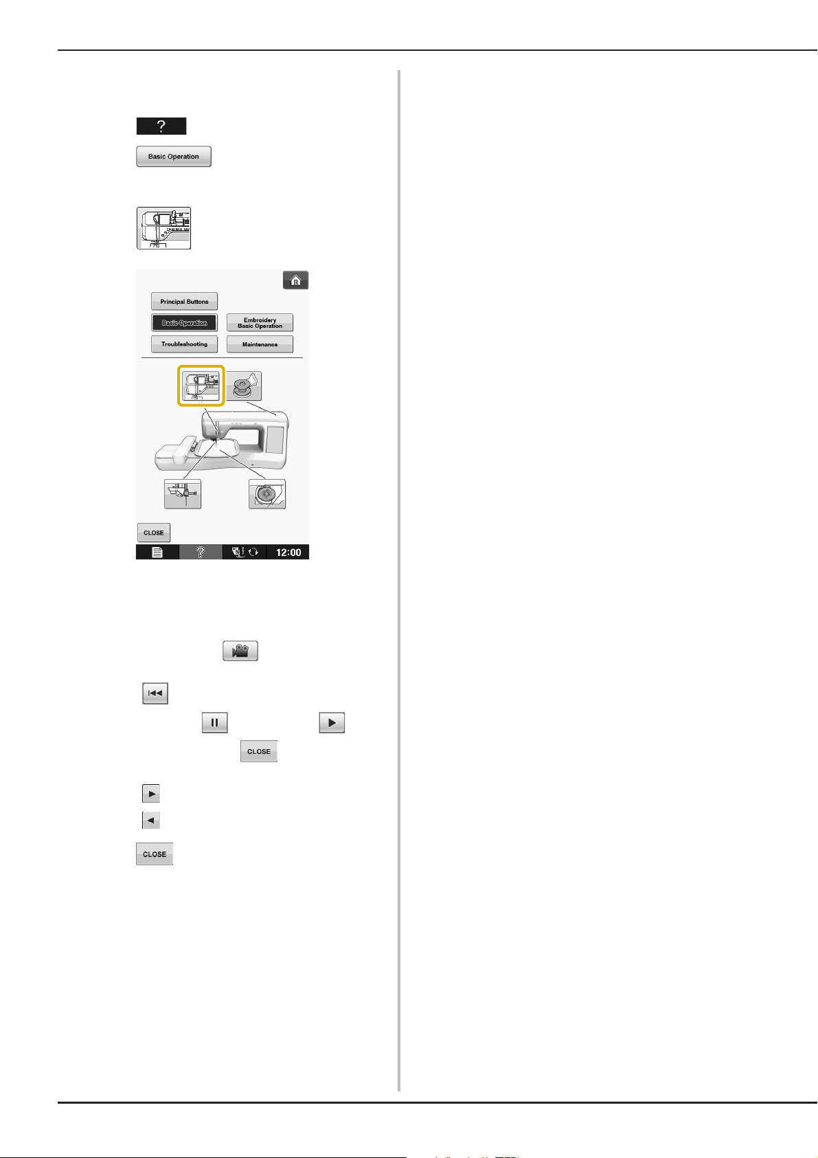
Press to open the machine help screen. Five categories are displayed at the top of the screen.
Press a key to see more information about that category.
displays information about
the operation buttons.
threading the machine, etc. Some of the
functions are described in the movies. Watch
these movies for a better understanding of
the functions. Certain individual threading
screens are animated.
displays information about
displays information about
attaching the embroidery unit, changing
embroidery feet, preparing fabric for
embroidering, checking the tension, etc.
B
1
Getting Ready
information.
displays troubleshooting
displays information about
cleaning the machine, etc.
Basic operations B-29
Page 32
LCD SCREEN
Example: Displaying information about
upper threading
Press .
a
Press .
b
→ The lower half of the screen will change.
Press (upper threading).
c
→ The screen shows instructions for threading the
machine.
Read the instructions.
d
* To view video, press of the displayed
instructions.
Press under movie to go back to the
beginning. Press to pause. Press to
restart after pause. Press to close out the
movie.
* Press to view the next page.
* Press to view the previous page.
Press to return to the original screen.
e
B-30
Page 33

LOWER THREADING
CAUTION
Winding the Bobbin
Press → → →
in this order to display a video example of
bobbin winding on the LCD (see page B-30).
Follow the steps explained below to complete the
operation.
• The included bobbin was designed specifically
for this machine. If bobbins from other models
are used, the machine will not operate
correctly. Use only the included bobbin or
bobbins of the same type (part code:
X52800-150).
LOWER THREADING
■ Using the Supplemental Spool Pin
With this machine, you can wind the bobbin
without unthreading the machine. While using the
main spool pin to sew, you can conveniently wind
the bobbin using the supplemental spool pin.
B
1
Getting Ready
* Actual size
a This model
b Other models
c 11.5 mm (approx. 7/16 inch)
a Supplemental spool pin
Turn the main power to ON and open the
a
top cover.
Align the groove in the bobbin with the
b
spring on the bobbin winder shaft, and set
the bobbin on the shaft.
a Groove in the bobbin
b Spring on the shaft
Basic operations B-31
Page 34
LOWER THREADING
CAUTION
Memo
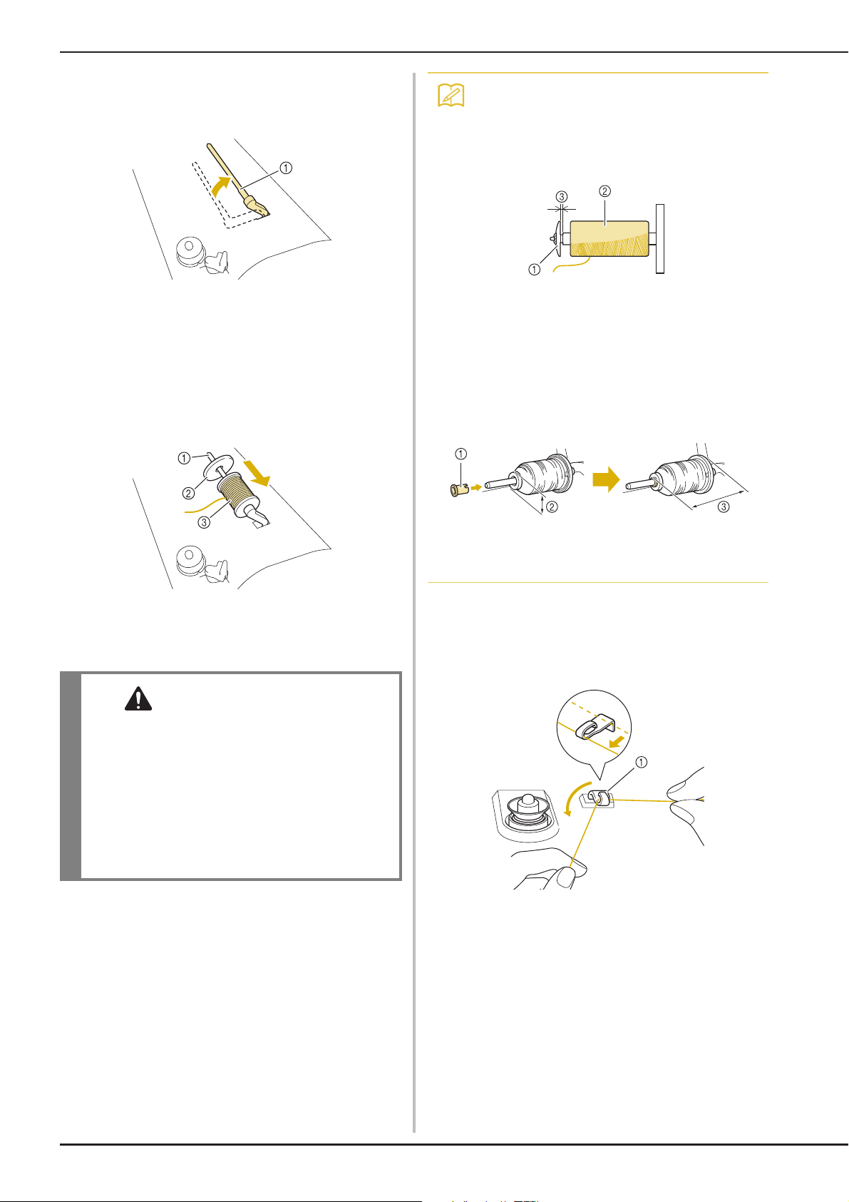
Set the supplemental spool pin in the “up”
c
position.
• When sewing with fine, cross-wound
thread, use the small spool cap, and leave a
small space between the cap and the
thread spool.
a Supplemental spool pin
Place the spool of thread on the
d
supplemental spool pin, so that thread
unrolls from the front. Push the spool cap
onto the spool pin as far as possible to
secure the thread spool.
a Spool pin
b Spool cap
c Thread spool
a Spool cap (small)
b Thread spool (cross-wound thread)
c Space
• If a spool of thread whose core is 12 mm
(1/2 inch) in diameter and 75 mm (3 inches)
high is inserted onto the spool pin, use the
mini spool insert.
a Spool cap (mini insert)
b 12 mm (1/2 inch)
c 75 mm (3 inches)
With your right hand, hold the thread near
e
the thread spool. With your left hand, hold
the end of the thread, and use both hands to
pass the thread through the thread guide.
• If the thread spool and/or spool cap are set
incorrectly, the thread may tangle on the spool
pin and cause the needle to break.
• Use the spool cap (large, medium, or small)
that is closest in size to the thread spool. If a
spool cap smaller than the thread spool is
used, the thread may become caught in the slit
on the end of the spool and cause the needle
to break.
a Thread guide
B-32
Page 35

LOWER THREADING
CAUTION
Memo
Pass the thread around the pre-tension disk
f
making sure that the thread is under the
pre-tension disk.
a Pre-tension disk
→ Make sure that the thread passes under the
pre-tension disk.
b Pre-tension disk
c Pull it in as far as possible.
→ Check to make sure thread is securely set between
pre-tension disks.
Wind the thread clockwise around the
g
bobbin 5-6 Times.
Pass the end of the thread through the guide
h
slit in the bobbin winder seat, and pull the
thread to the right to cut the thread with
the cutter.
a Guide slit (with built-in cutter)
b Bobbin winder seat
• Be sure to follow the process described. If the
thread is not cut with the cutter, and the
bobbin is wound, when the thread runs low it
may tangle around the bobbin and cause the
needle to break.
Set the bobbin winding switch to the left,
i
until it clicks into place.
B
1
Getting Ready
a Bobbin winding switch
• Sliding the bobbin winding switch to the left
switches the machine into bobbin winding
mode.
→ The bobbin winding window appears.
Basic operations B-33
Page 36

LOWER THREADING
Note
Memo
Memo
CAUTION
Press .
j
→ Bobbin winding starts automatically. The bobbin
stops rotating when bobbin winding is completed.
The bobbin winding switch will automatically return
to its original position.
• changes to while the bobbin
is winding.
• Stay near the machine while winding the
bobbin to make sure the bobbin thread is
being wound correctly. If the bobbin thread
is wound incorrectly, press
immediately to stop the bobbin winding.
• The sound of winding the bobbin with stiff
thread, such as nylon thread for quilting,
may be different from the one produced
when winding normal thread; however, this
is not a sign of a malfunction.
Cut the thread with scissors and remove the
k
bobbin.
• When removing the bobbin, do not pull on
the bobbin winder seat. Doing so could
loosen or remove the bobbin winder seat,
and could result in damage to the machine.
• Setting the bobbin improperly may cause the
thread tension to loosen, breaking the needle
and possibly resulting in injury.
• You can change the winding speed by
pressing (to decrease) or (to
increase) in the bobbin winding window.
• Press to minimize the bobbin
winding window. Then, you can perform
other operations, such as selecting a
pattern or adjusting the thread tension,
while the bobbin is being wound.
• Press (in top right of the LCD screen)
to display the bobbin winding window
again.
■ Using the Spool Pin
You can use the main spool pin to wind the bobbin
before sewing. You cannot use this spool pin to
wind the bobbin while sewing.
B-34
Page 37

LOWER THREADING
CAUTION
Turn the main power to ON and open the
a
top cover.
Align the groove in the bobbin with the
b
spring on the bobbin winder shaft, and set
the bobbin on the shaft.
a Groove in the bobbin
b Spring on the shaft
Pivot the spool pin so that it angles upward.
c
Set the thread spool on the spool pin so that
the thread unwinds from the front of the
spool.
Pass the thread through the thread guide.
f
a Thread guide
Pass the thread around the pre-tension disk
g
making sure that the thread is under the
pre-tension disk.
B
1
Getting Ready
a Spool pin
b Spool cap
c Thread spool
d Spool felt
Push the spool cap onto the spool pin as far
d
as possible, then return the spool pin to its
original position.
While holding the thread with both hands,
e
pull the thread up from under the thread
guide plate.
a Thread guide
b Pre-tension disk
Follow steps g through k on page B-33
h
through B-34.
■ Untangling Thread from Beneath the
Bobbin Winder Seat
If the bobbin winding starts when the thread is not
passed through the pre-tension disk correctly, the
thread may become tangled beneath the bobbin
winder seat.
Wind off the thread according to the following
procedure.
a Thread
b Bobbin winder seat
a Thread guide plate
• Do not remove the bobbin winder seat even if
the thread becomes tangled under the bobbin
winder seat. It may result in injuries.
Basic operations B-35
Page 38

LOWER THREADING
Note
CAUTION
If the thread becomes tangled under the
a
bobbin winder seat, press once to
stop the bobbin winding.
Cut the thread with scissors near the
b
pre-tension disk.
a Pre-tension disk
Setting the Bobbin
Press → → →
in this order to display a video example of
the operation on the LCD (see page B-30). Follow
the steps explained below to complete the
operation.
• Use a bobbin thread that has been correctly
wound. Otherwise, the needle may break or
the thread tension will be incorrect.
Push the bobbin winder switch to the right,
c
and then raise the bobbin at least 10 cm
(4 inches) from the shaft.
Cut the thread near the bobbin and hold the
d
thread end with your left hand. Unwind the
thread clockwise near the bobbin winder
seat with your right hand as shown below.
• The included bobbin was designed specifically
for this machine. If bobbins from other models
are used, the machine will not operate
correctly. Use only the included bobbin or
bobbins of the same type (part code:
X52800-150).
* Actual size
a This model
b Other models
c 11.5 mm (approx. 7/16 inch)
• Before inserting or changing the bobbin, be
sure to press in the LCD, otherwise
injuries may occur if the “Start/Stop” button
or any other button is pressed and the machine
starts sewing.
Wind the bobbin again.
e
• Make sure that the thread passes through
the pre-tension disk correctly (page B-33).
B-36
Press .
a
Page 39
LOWER THREADING
CAUTION
Memo
CAUTION
1
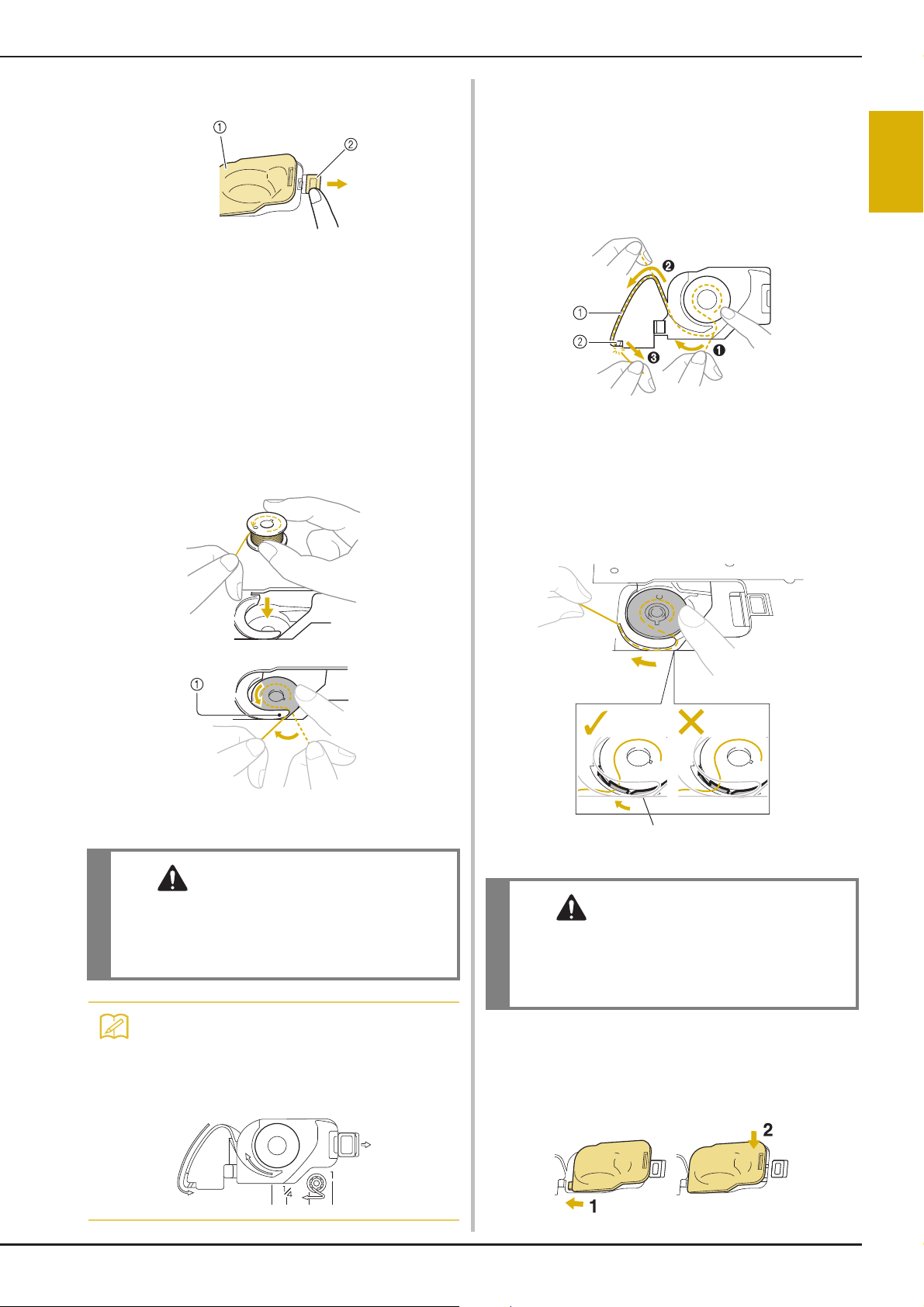
Slide the bobbin cover latch to the right.
b
a Bobbin cover
b Latch
→ The bobbin cover opens.
Remove the bobbin cover.
c
Insert the bobbin with your right hand so
d
that the end of the thread is on the left, and
then, after pulling the thread firmly around
the tab with your left hand as shown, lightly
pull the thread to guide it through the slit.
While lightly holding down bobbin with
e
your right hand as shown, guide the thread
through the slit (a and b).
* At this time, check that the bobbin easily rotates
counterclockwise.
Then, pull the thread toward you to cut it
with the cutter (c).
a Slit
b Cutter (Cut the thread with the cutter.)
→ The cutter cuts the thread.
Make sure that the thread is correctly
passed through the flat spring of the bobbin
case. If it is not inserted correctly, reinstall
the thread.
B
1
Getting Ready
a Tab
* Be sure to insert the bobbin correctly.
• Be sure to install the bobbin so that the thread
unwinds in the correct direction, otherwise
the thread may break or the thread tension will
be incorrect.
• The order that the bobbin thread should be
passed through the bobbin case is
indicated by marks around the bobbin case.
Be sure to thread the machine as indicated.
a Flat spring
• Be sure to hold down the bobbin with your
finger and unwind the bobbin thread
correctly. Otherwise, the thread may break or
the thread tension will be incorrect.
Insert the tab in the lower-left corner of the
f
bobbin cover (1), and then lightly press
down on the right side to close the cover
(2).
Basic operations B-37
Page 40
UPPER THREADING
CAUTION
Memo
Memo
Note
UPPER THREADING
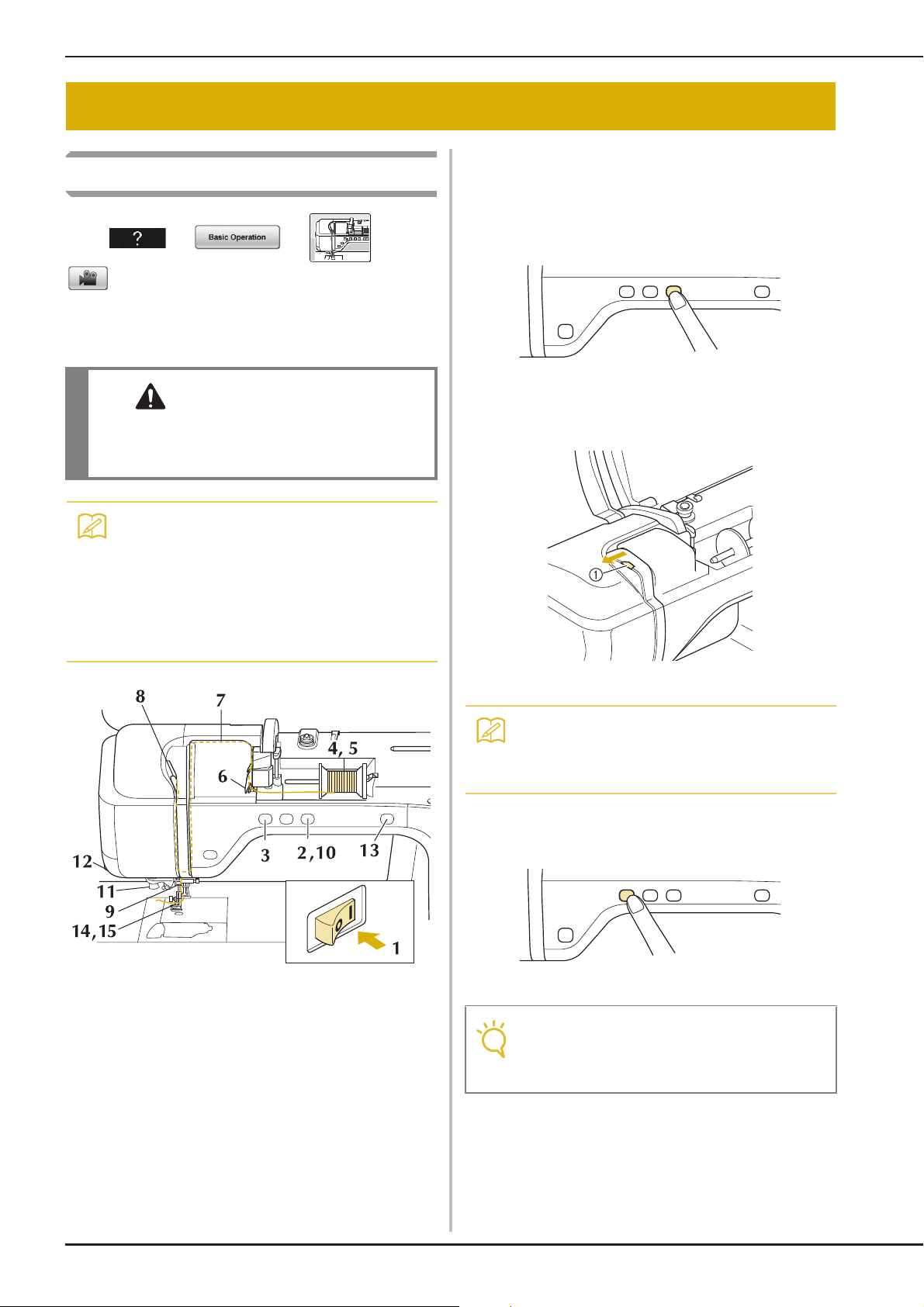
Upper Threading
Press → → →
in this order to display a video example of
the operation on the LCD (see page B-30). Follow
the steps explained below to complete the
operation.
• Be sure to thread the machine properly.
Improper threading can cause the thread to
tangle and break the needle, leading to injury.
Turn the main power to ON.
a
Press the “Presser Foot Lifter” button to
b
raise the presser foot.
→ The upper thread shutter opens so the machine can
be threaded.
• The automatic threading function can be
used with embroidery machine needle sizes
75/11 through 90/14.
• Thread such as transparent nylon
monofilament thread and thread with a
thickness of 130/20 or thicker cannot be
used with the automatic threading function.
a Upper thread shutter
• This machine is equipped with an upper
thread shutter, allowing you to check that
the upper threading is performed correctly.
Press the “Needle Position” button to raise
c
the needle.
B-38
• If you try to thread the needle automatically
without raising the needle, the thread may
not thread correctly.
Page 41

Pivot the spool pin so that it angles upward.
CAUTION
Memo
d
Set the thread spool on the spool pin so that
the thread unwinds from the front of the
spool.
a Spool pin
b Spool cap
c Thread spool
d Spool felt
Push the spool cap onto the spool pin as far
e
as possible, then return the spool pin to its
original position.
UPPER THREADING
• When sewing with fine, cross-wound
thread, use the small spool cap, and leave a
small space between the cap and the
thread spool.
a Spool cap (small)
b Thread spool (cross-wound thread)
c Space
• If a spool of thread whose core is 12 mm
(1/2 inch) in diameter and 75 mm (3 inches)
high is inserted onto the spool pin, use the
mini spool insert.
B
1
Getting Ready
• If the thread spool and/or spool cap are set
incorrectly, the thread may tangle on the spool
pin and cause the needle to break.
• Use the spool cap (large, medium, or small)
that is closest in size to the thread spool. If a
spool cap smaller than the thread spool is
used, the thread may become caught in the slit
on the end of the spool and cause the needle
to break.
a Spool cap (mini insert)
b 12 mm (1/2 inch)
c 75 mm (3 inches)
While holding the thread with both hands,
f
pull the thread up from under the thread
guide plate.
a Thread guide plate
While holding the thread in your right
g
hand, pass the thread through the thread
guide in the direction indicated.
Basic operations B-39
Page 42

UPPER THREADING
Memo
Note
Guide the thread down, up, then down
h
through the groove, as shown in the
illustration.
• Look in the upper groove area to check if
the thread catches on the take-up lever
visible inside the upper groove area.
Pass the thread through the thread guide
k
disks (marked “7”). Make sure that the
thread passes through the groove in the
thread guide.
a Groove in thread guide
Pull the thread up through the thread cutter
l
to cut the thread, as shown in the
illustration.
a Look in the upper groove area
Pass the thread through the needle bar
i
thread guide (marked “6”) by holding the
thread with both hands and guiding it as
shown in the illustration.
a Needle bar thread guide
Press the “Presser Foot Lifter” button to
j
lower presser foot.
a Thread cutter
• When using thread that quickly winds off
the spool, such as metallic thread, it may be
difficult to thread the needle if the thread is
cut.
Therefore, instead of using the thread
cutter, pull out about 80 mm (approx. 3
inches) of thread after passing it through the
thread guide disks (marked “7”).
a 80 mm (approx. 3 inches) or more
B-40
Page 43

Press the “Automatic Threading” button to
Memo
Note
Memo
Note
Memo
m
have the machine automatically thread the
needle.
UPPER THREADING
• If the needle could not be threaded or the
thread was not passed through the needle
bar thread guides, perform the procedure
again starting from step
Then, pass the thread through the eye of
the needle after step
c.
i.
B
1
Getting Ready
→ The thread passes through the eye of the needle.
• When the “Automatic Threading” button is
pressed, the presser foot will be
automatically lowered. After threading is
finished, the presser foot moves back to the
position before the “Automatic Threading”
button was pressed.
Carefully pull the end of the thread that was
n
passed through the eye of the needle.
* If a loop was formed in the thread passed through
the eye of the needle, carefully pull on the loop of
thread through to the back of the needle.
• Some needles cannot be threaded with the
needle threader. In this case, instead of
using the needle threader after passing the
thread through the needle bar thread guide
(marked “6”), manually pass the thread
through the eye of the needle from the front
to the back.
Pulling Up the Bobbin Thread
There may be some applications where you want
to pull up the bobbin thread; for example, when
embroidering bobbin work designs.
• Pulling the loop of thread gently will avoid
needle breakage.
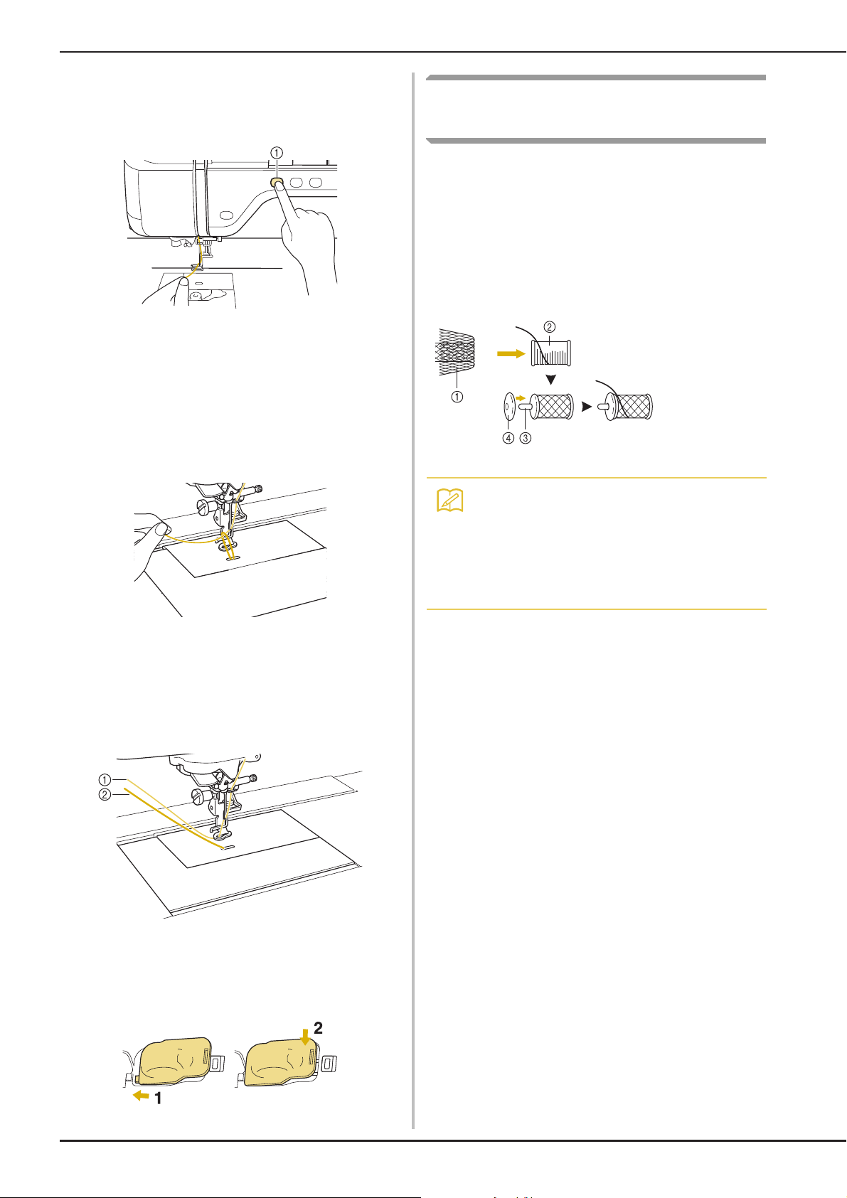
Pull out about 10-15 cm (approx. 4-6
o
inches) of the thread, and then pass it under
the presser foot toward the rear of the
machine.
→ Raise the presser foot lever if the presser foot is
lowered.
a About 10-15 cm (approx. 4-6 inches)
• You can pull up the bobbin thread after
threading the upper thread (“UPPER
THREADING” on page B-38).
Guide the bobbin thread through the
a
groove, following the arrow in the
illustration.
* Do not cut the thread with the cutter.
* Do not replace the bobbin cover.
Basic operations B-41
Page 44
UPPER THREADING
Memo
While holding the upper thread, press the
b
“Needle Position” button to lower the
needle.
Using Threads that Unwind
Quickly
■ Using the Spool Net
If using transparent nylon monofilament thread,
metallic thread, or other strong thread, place the
included spool net over the spool before using it.
When using specialty threads, threading must be
done manually.
If the spool net is too long, fold it once to match it to
the spool size before placing it over the spool.
a “Needle Position” button
Press the “Needle Position” button to raise
c
the needle.
Gently pull the upper thread. A loop of the
d
bobbin thread will come out of the hole in
the needle plate.
Pull up the bobbin thread, pass it under the
e
presser foot and pull it about
100 mm (approx. 4 inches) toward the back
of the machine, making it even with the
upper thread.
a Spool net
b Thread spool
c Spool pin
d Spool cap
• When threading the spool with the spool net
on, make sure that 5 cm - 6 cm (approx.
2 inches - 2-1/2 inches) of thread are pulled
out.
• It may be necessary to adjust the thread
tension when using the spool net.
f
B-42
a Upper thread
b Bobbin thread
Replace the bobbin cover.
Page 45

BEFORE EMBROIDERING
Step 7
Step 2
Step 1
Step 3, 8
Step 9
Step 4, 5
Step 6
Embroidery Step by Step
Follow the steps below to prepare the machine for embroidery.
BEFORE EMBROIDERING
B
1
Getting Ready
Step # Aim Action Page
1 Bobbin thread setup For the bobbin thread, wind embroidery bobbin thread and set it in place. B-31
2 Fabric preparation Attach a stabilizer material to the fabric, and hoop it in the embroidery frame. E-11 to
3 Pattern selection Turn the main power to ON, and select an embroidery pattern. E-3
4 Checking the needle Use needle 75/11 for most embroidering. B-50
5 Embroidery foot attaching Attach embroidery foot “W+” with LED pointer. B-46
6 Embroidery unit attaching Attach the embroidery unit. B-44
7 Embroidery frame attachment Attach the embroidery frame to the embroidery unit. E-17
8 Checking the layout Check and adjust the size and position of the embroidery. E-19
9 Embroidery thread setup Set up embroidery thread according to the pattern. E-21
* It is recommended that a 90/14 needle should be used when embroidering on heavy weight fabrics or stabilizing products (for example;
denim, puffy foam, etc.).
E-17
Basic operations B-43
Page 46

BEFORE EMBROIDERING
CAUTION
Note
Note
Note
CAUTION
About the Embroidery Unit
■ Attaching the Embroidery Unit
• Do not move the machine with the embroidery
unit attached. The embroidery unit could fall
off and cause injury.
• Keep your hands and foreign objects away
from the embroidery carriage and frame when
the machine is embroidering. Otherwise,
injury may result.
• To avoid distorting your embroidery design, do
not touch the embroidery carriage and frame
when the machine is embroidering.
• Be sure to turn off the power before
installing the embroidery unit. Otherwise,
the machine may be damaged.
• Do not touch the inner connector of the
embroidery unit. The pins on the
embroidery unit connection may be
damaged.
• Do not apply strong force to the embroidery
unit carriage or pick up the unit by the
carriage. Otherwise, the embroidery unit
may be damaged.
• When not using or when transporting the
embroidery unit, pack it securely in the
shipping carton box.
• Be sure there is no gap between the
embroidery unit and the machine. If there is
a gap, the embroidery patterns will not
embroider with the correct registration.
• Do not push on the carriage when installing
the embroidery unit onto the machine.
Moving the carriage may damage the
embroidery unit.
Turn the main power to ON.
c
→ The following message will appear.
Press .
d
→ The carriage will move to the initialization position.
Turn the main power to OFF.
a
Insert the embroidery unit connection into
b
the machine connection port. The spring
hinge on the connection port cover will
allow easy access to the port. Push lightly
on the connection port cover until the unit
clicks into place.
a Embroidery unit connection
b Machine connection port
• Either “Embroidery” screen or “Embroidery
Edit” screen appears, depending on the
setting selected in the settings screen.
■ Removing the Embroidery Unit
Press either (Embroidery) or
a
(Embroidery Edit), then press .
→ The carriage will move to the removal position.
• Always remove the embroidery frame before
pressing . Otherwise, the frame may
strike the embroidery foot, and possibly cause
injury.
• The embroidery unit will not fit in the shipping
carton box if this step is not done.
B-44
Page 47

The warning message “The carriage of the
Note
CAUTION
b
embroidery unit will move. Keep your
hands etc. away from the carriage.”
appears. Press and turn the main
power OFF.
BEFORE EMBROIDERING
B
1
• Be sure to turn off the machine before
removing the embroidery unit, otherwise
damage to the machine may result.
Hold down the release button, and pull the
c
embroidery unit away from the machine.
Getting Ready
a Release button
• Do not carry the embroidery unit by holding
the release button compartment.
Basic operations B-45
Page 48
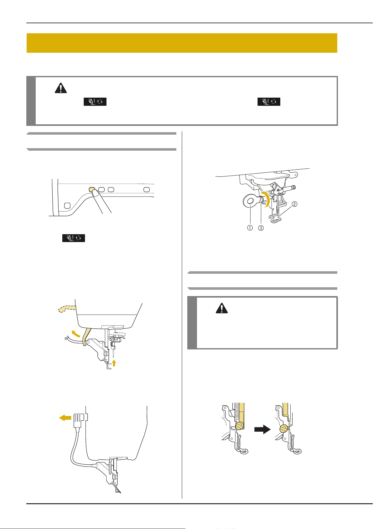
CHANGING THE EMBROIDERY FOOT
CAUTION
CAUTION
CHANGING THE EMBROIDERY FOOT
The embroidery foot is attached to the machine when purchased, with the connector of the embroidery
foot “W+” with LED pointer unplugged from the machine.
• Always press on the screen before changing the embroidery foot. If is not pressed and
the “Start/Stop” button or another button is pressed, the machine will start and may cause injury.
• Only use embroidery feet made for this machine. Using other presser feet may lead to accident or injury.
Use the included screwdriver to loosen the
Removing the Embroidery Foot
Press the “Needle Position” button to raise
a
the needle.
e
screw of the embroidery foot, then remove
the embroidery foot.
Press .
b
* If the message “OK to automatically lower the
presser foot? ” appears on the LCD screen, press OK
to continue.
→ The entire screen becomes white, and all keys and
operation buttons are locked.
Raise the presser foot lever.
c
Unplug the connector of the embroidery
d
foot “W+” from the jack on the back of the
machine.
a Screwdriver
b Embroidery foot
c Embroidery foot screw
→ Remove the embroidery foot.
Attaching the Embroidery Foot
• Make sure that the embroidery foot is installed
in the correct direction, otherwise the needle
may strike the embroidery foot, breaking the
needle and causing injuries.
Position the embroidery foot “W+” with
a
LED pointer on the presser foot bar by
aligning the notch of the presser foot to the
large screw.
Side view
B-46
Page 49

CHANGING THE EMBROIDERY FOOT
CAUTION
Memo
Note
Hold the embroidery foot in place with
b
your right hand, and then use the included
screwdriver to securely tighten the
embroidery foot screw.
• Use the included screwdriver to firmly tighten
the screw of the embroidery foot. If the screw
is loose, the needle may strike the embroidery
foot and possibly cause injury.
Plug the connector of the embroidery foot
c
“W+” with LED pointer into the jack on the
back of your machine.
■ Checking the Needle Drop Point
With the Embroidery Foot “W+”
with LED Pointer
Before beginning to embroider when using the
embroidery foot “W+” with LED pointer, carefully
read the procedures described in the “Embroidery”
and “Embroidery Edit” chapters.
Press in the embroidery screen.
a
→ The LED pointer indicates the needle drop point.
B
1
Getting Ready
Press to unlock all keys and
d
buttons.
→ All keys and operation buttons are unlocked, and
the previous screen is displayed.
• When the LED pointer is turned on, the
presser foot height is automatically adjusted
according to the fabric thickness.
• If is pressed again, the fabric thickness
is remeasured and the presser foot is set to
the optimum height.
* The LED pointer turns off automatically by lowering
the presser foot or returning to the previous page.
• With bulky fabrics, the position may not be
accurate due to the various depths of the
fabrics. In this case, manually adjust the
position according to the thickness of the
fabric.
• With fabric that has a very uneven surface
such as quilting, the fabric thickness may
not be correctly measured. In this case, the
pointer indication should be used only as a
reference.
Basic operations B-47
Page 50
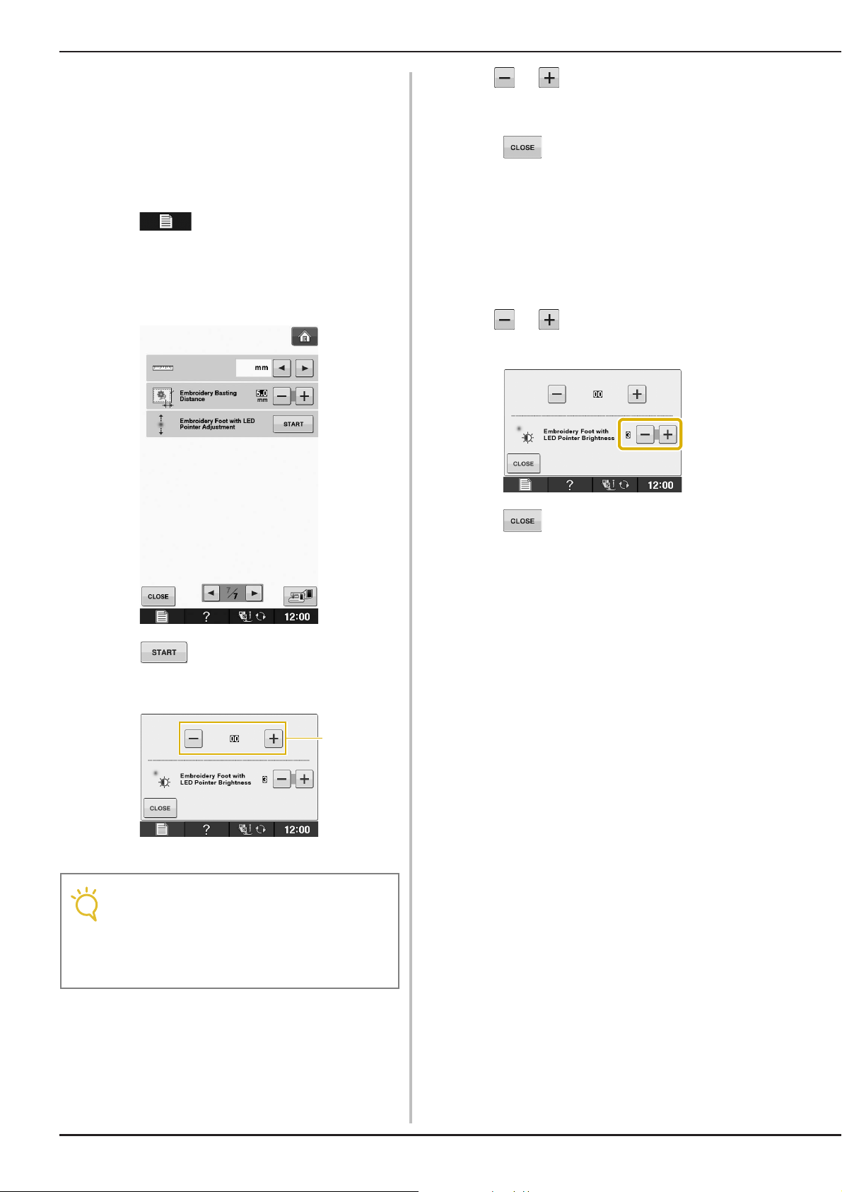
CHANGING THE EMBROIDERY FOOT
Note
a
■ Adjusting the LED Pointer
Adjust the LED pointer if it indicates a point different
than the actual needle drop point.
Before adjusting the LED pointer, mark the actual
needle drop point on the fabric to be embroidered,
and then hoop the fabric and attach the embroidery
frame.
Press .
a
→ The settings screen appears.
Display page 7 of the Embroidery settings
b
screen.
Use or to adjust the LED pointer so
d
that it indicates the actual needle drop
point.
Press twice to return to the original
e
screen.
■ Adjusting the Brightness of the LED
Pointer
Follow the steps from a to d to display
a
the embroidery foot with LED pointer
adjustment screen.
Use or to adjust the brightness of
b
the LED pointer.
Press .
c
→ The Embroidery Foot “W+” with LED Pointer
Adjustment screen appears.
a LED pointer adjustment
• The specified setting is saved in the
machine’s memory. This is useful for
positioning during continuous
embroidering.
• For normal use, return the setting to “00”.
Press twice to return to the original
c
screen.
B-48
Page 51
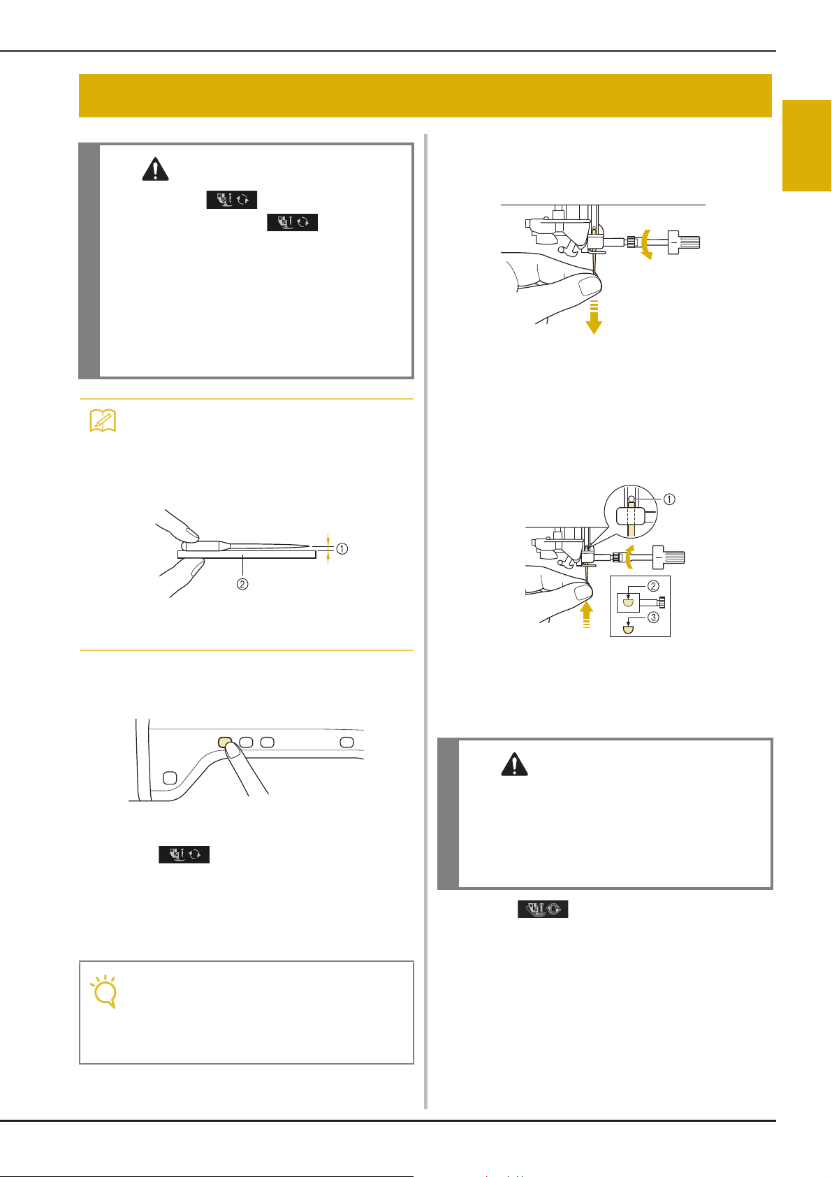
CHANGING THE NEEDLE
CAUTION
Memo
Note
CAUTION
• Always press on the screen before
changing the needle. If is not pressed
and the Start/Stop button or another operation
button is pressed accidentally, the machine
will start and injury may result.
• Use only embroidery machine needles made
for home use. Other needles may bend or
break and may cause injury.
• Never sew with a bent needle. A bent needle
will easily break and may cause injury.
• To check the needle correctly, place the flat
side of the needle on a flat surface. Check
the needle from the top and the sides.
Throw away any bent needles.
CHANGING THE NEEDLE
Use the screwdriver to turn the screw
c
toward the front of the machine and loosen
the screw. Remove the needle.
With the flat side of the needle facing the
d
back, insert the new needle all the way to
the top of the needle stopper (viewing
window) in the needle clamp. Use a
screwdriver to securely tighten the needle
clamp screw.
B
1
Getting Ready
a Parallel space
b Level surface (bobbin cover, glass, etc.)
Press the “Needle Position” button to raise
a
the needle.
Press .
b
* If the message “OK to automatically lower the
presser foot? ” appears on the LCD screen, press OK
to continue.
→ The entire screen becomes white, and all keys and
operation buttons are locked.
• Before replacing the needle, cover the hole
in the needle plate with fabric or paper to
prevent the needle from falling into the
machine.
a Needle stopper
b Hole for setting the needle
c Flat side of needle
• Be sure to push in the needle until it touches
the stopper, and securely tighten the needle
clamp screw with a screwdriver. If the needle
is not completely inserted or the needle clamp
screw is loose, the needle may break or the
machine may be damaged.
Press to unlock all keys and
e
buttons.
Basic operations B-49
Page 52

USING FUNCTIONS BY CONNECTING THE ACCESSORY TO THE MACHINE
Note
Memo
About the Needle
The needle is probably the most important part of the machine. Choosing the proper needle for your
embroidering project will result in a beautiful finish and fewer problems. Below are some things to keep
in mind about needles.
• Use needle 75/11 for embroidery.
• It is recommended that a 90/14 needle should be used when embroidering on heavyweight fabrics or
stabilizing products (for example, denim, puffy foam, etc.). A 75/11 needle may bend or break, which could
result in injury.
• The smaller the needle number, the finer the needles. As the numbers increase, the needles get thicker.
• Use fine (thinner) needles for lightweight fabrics, and thicker (larger) needles for heavyweight fabrics.
USING FUNCTIONS BY CONNECTING THE
ACCESSORY TO THE MACHINE
Using USB Media or Embroidery
Card Reader/USB Card Writer
Module*
* If you have purchased the Palette Ver5 or later,
Palette Petite or Palette PTS, you can plug the
included USB card writer module into the machine
as an embroidery card reader, and recall patterns.
• Use only an embroidery card reader
designed for this machine. Using an
unauthorized embroidery card reader may
cause your machine to operate incorrectly.
• Embroidery patterns cannot be saved from
the machine to an embroidery card inserted
into a connected USB card writer module.
a USB port for mouse / media (USB 2.0)
b USB media
• USB media is widely used, however some
USB media may not be usable with this
machine. Please visit our website for more
details.
• Depending on the type of USB media being
used, either directly plug the USB device
into the machine’s USB port or plug the
USB media Reader/Writer into the
machine’s USB port.
B-50
a USB port for mouse / media
b Embroidery card Reader/USB card writer module*
Page 53

USING FUNCTIONS BY CONNECTING THE ACCESSORY TO THE MACHINE
Note
Note
Note
Memo
a
Connecting the Machine to the
Computer
Using the included USB cable, the machine can be
connected to your computer.
a USB port for computer
b USB cable connector
Using a USB Mouse
The USB mouse, connected to the machine, can
be used to perform a variety of operations in the
screens.
• If a mouse other than the optional USB
mouse is used, it may not perform as
described in this Instruction and Reference
Guide.
B
1
Getting Ready
• The connectors on the USB cable can only
be inserted into a port in one direction. If it
is difficult to insert the connector, do not
insert it with force. Check the orientation of
the connector.
• For details on the position of the USB port
on the computer (or USB hub), refer to the
instruction manual for the corresponding
equipment.
a USB port for mouse / media
b USB mouse
• Do not perform operations with the mouse
at the same time that you are touching the
screen with your finger or the included
touch pen.
• A USB mouse can be connected or
disconnected at any time.
• The mouse pointer does not appear in the
opening screen.
■ Clicking a Key
When the mouse is connected, the pointer appears
on the screen. Move the mouse to position the
pointer over the desired key, and then click the left
mouse button.
• Double-clicking has no effect.
a Pointer
Basic operations B-51
Page 54
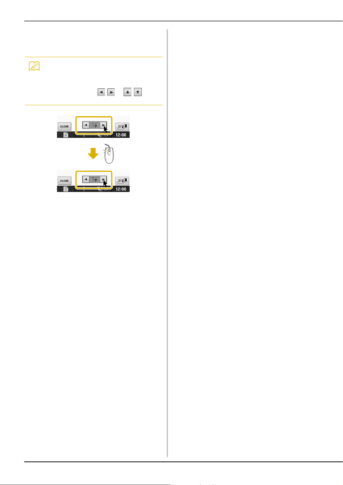
USING FUNCTIONS BY CONNECTING THE ACCESSORY TO THE MACHINE
Memo
■ Changing Pages
Rotate the mouse wheel to switch through the tabs
of the pattern selection screens.
• If page numbers and a vertical scroll bar for
additional pages are displayed, rotate the
mouse wheel or click the left mouse button
with the pointer on / or / to
display the previous or next page.
B-52
Page 55

USING FUNCTIONS BY CONNECTING THE ACCESSORY TO THE MACHINE
B
1
Getting Ready
Basic operations B-53
Page 56

B Basic operations
Note
Chapter 2
Sensor Functions
CONNECTING THE SENSOR PEN...........................55
Using the Sensor Pen Holder ....................................................55
USING THE SENSOR PEN........................................57
Using the Sensor Pen ................................................................57
Important Information about Sensor Pen..................................57
Calibrating the Sensor Pen........................................................58
USING SENSOR FUNCTIONS IN
“EMBROIDERY”/“EMBROIDERY EDIT” MODE ......60
Specifying the Embroidering Position With the Sensor Pen....... 60
■ Selecting the Embroidering Position by the Pattern Edge......... 61
■ Selecting the Embroidering Position by the Pattern Center...... 62
• Sensor functions and the sensor
pen may not be available in some
countries or regions.
Page 57
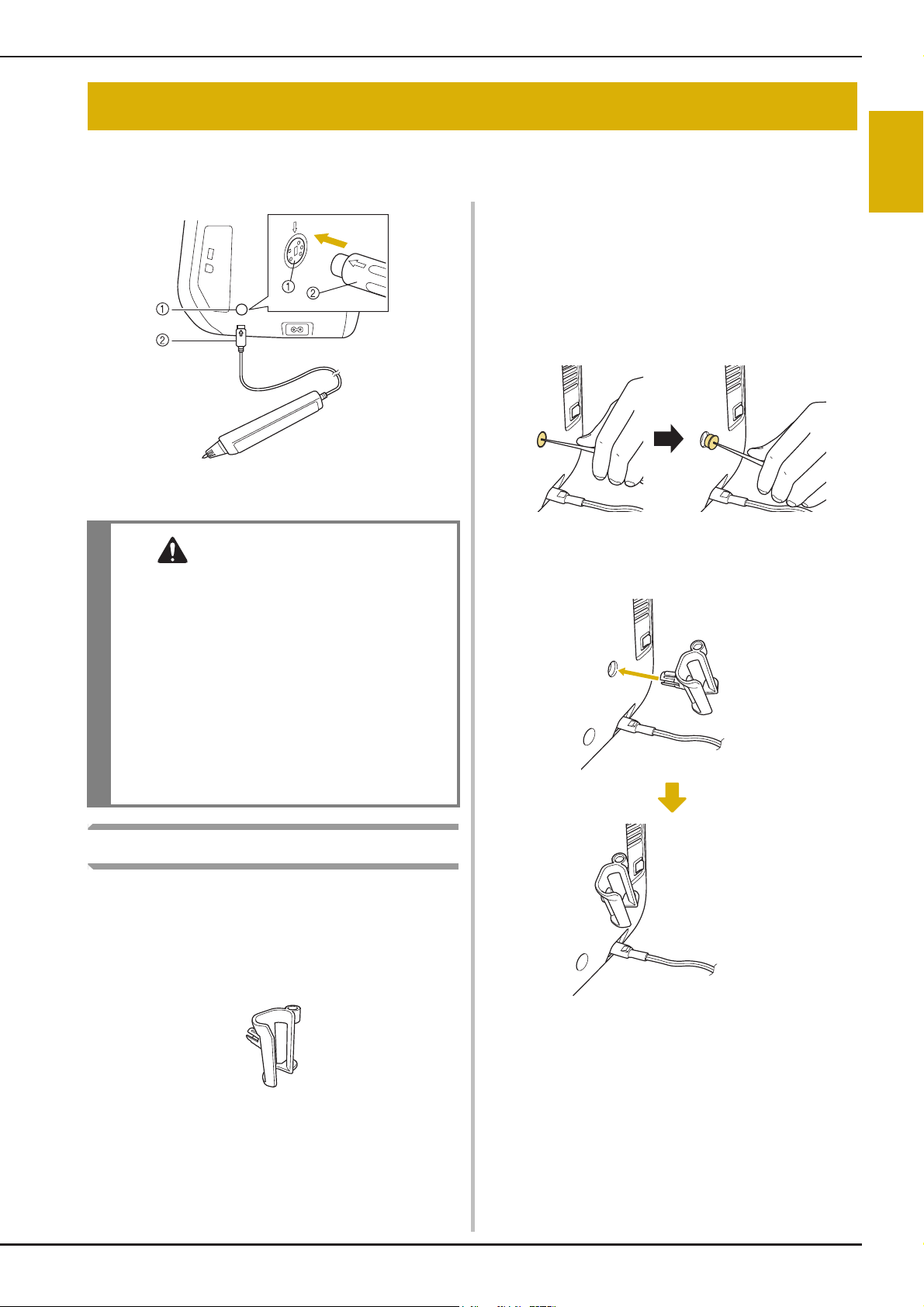
CONNECTING THE SENSOR PEN
CAUTION
CONNECTING THE SENSOR PEN
When connecting the sensor pen to the machine, make sure that the arrow on the sensor pen connector
faces up, lines up with the arrow on the machine, and that the connector is firmly inserted into the jack.
Insert the point end of the cleaning brush or
a
the seam ripper point into the hole in the
protective cap on the right side of the
machine. Lightly pull out the protective cap
to remove it.
→ Insert the point of the seam ripper or cleaning brush
into the hole in the protective cap, and then lightly
pull out the protective cap to remove it.
a Sensor pen jack
b Sensor pen connector
B
2
Sensor Functions
• When connecting the sensor pen, make sure
that the arrow on the sensor pen connector
faces up and aligns with the arrow on the
machine, otherwise the connector pins will
not align correctly and the connector will be
damaged.
• When connecting or disconnecting the sensor
pen, grab the connector, and then slowly push
it straight in or pull it straight out.
• When disconnecting the sensor pen from the
machine, do not pull on the cord, otherwise
the sensor pen may be damaged.
Using the Sensor Pen Holder
Before connecting the sensor pen to the machine,
attach the sensor pen holder to keep the sensor
pen with the machine.
The right side of the holder can be used to hold the
touch pen.
Firmly insert the sensor pen holder into the
b
hole where the protective cap was
removed.
Sensor pen holder
Basic operations B-55
Page 58

CONNECTING THE SENSOR PEN
Set the sensor pen in the sensor pen holder
c
with the pen tip pointing downward, and
then connect the sensor pen to the
machine.
B-56
Page 59

USING THE SENSOR PEN
Note
Memo
CAUTION
IMPORTANT
USING THE SENSOR PEN
B
Using the Sensor Pen
Hold the sensor pen, and then touch the point to
be specified. When the tip of the sensor pen is
pushed in, the position information is sent to the
machine.
When using the sensor pen, touch slowly and
gently for the definite operation.
1) Touch: Touch a point with the sensor pen, then
immediately lift up the pen.
2) Long touch: Touch a point with the sensor pen
and hold it down for at least one second to
activate the functions that you just selected.
Important Information about
Sensor Pen
The sensor pen emits the signal to the machine,
and then the sensor pen receiver receives the
signal to specify the position.
a Sensor pen receiver inside the machine
b Signal is waved out from the sensor pen
• Do not insert any object into the sensor pen
and the receiver, otherwise the machine may
be damaged.
2
Sensor Functions
• Once a point is touched with the sensor pen
and the entered information is applied in the
screen, perform the next operation.
Repeatedly touching a point with the sensor
pen may prevent the information from being
correctly read.
• Do not drag the sensor pen tip on the
machine, otherwise the sensor pen tip may
be chipped off.
• If there is any problem with the guideline
marker, the sensor function may not
operate correctly.
• The sensor pen can be used to touch on the
screen as a touch pen.
• Do not put your hand, the fabric or any object
between the machine and the sensor pen,
otherwise the sensor pen receiver may not
receive the ultrasonic wave.
• Do not use the machine close to any other unit
which produces ultrasonic wave or a vibration
sound, otherwise interference may occur.
Basic operations B-57
Page 60

USING THE SENSOR PEN
Calibrating the Sensor Pen
Before using the sensor pen for the first time be
sure to calibrate it to the screen. Doing so allows
the machine to learn the position you usually hold
a pen.
Hold the sensor pen at a comfortable angle and
then calibrate the machine according to the
procedure below.
Be sure to keep the sensor pen at the same angle
while calibrating the first and second points.
First touch the green dot marking on the
d
needle plate cover using the sensor pen.
* Touch on the needle plate cover.
Press .
a
Display page 3 of the settings screen.
b
Connect the sensor pen to the machine and
c
then press .
→ The Sensor Function Calibration screen appears.
a Needle plate cover
* A beep will sound and the a will change to red. (If
the beep is not heard, check that the volume setting
on page 1/7 of the settings is set at 1 or higher and
then touch a again.)
* Press to redo the first point by starting over
from step c.
B-58
Page 61

Touch the second point at the center of the
e
cross-hair using the sensor pen.
* Touch on the point in the illustration.
USING THE SENSOR PEN
B
2
Sensor Functions
a Embroidery unit
Press to finish the calibration. To
f
repeat the calibration touch the first point
again using the sensor pen, and continue
with step
* Press to return to the original screen without
finishing the calibration.
* Press to reset the calibration.
e.
Basic operations B-59
Page 62

USING SENSOR FUNCTIONS IN “EMBROIDERY”/“EMBROIDERY EDIT” MODE
USING SENSOR FUNCTIONS IN
“EMBROIDERY”/“EMBROIDERY EDIT” MODE
Before using the sensor functions, carefully read the procedure in “Embroidery” and “Embroidery Edit” to
familiarize yourself with the machine operations.
Press .
g
Specifying the Embroidering
Position With the Sensor Pen
By using the sensor pen, the embroidering position
can be adjusted to the desired location. This
function can be performed in either “Embroidery”
or “Embroidery Edit” mode, but the procedure
described below is performed in “Embroidery”
mode.
If the message “The carriage of the embroidery
unit will move. Keep your hands etc. away from
the carriage.” appears during the operation, ensure
safety, and then press .
Turn on the machine.
a
Press (Embroidery) or
b
(Embroidery Edit).
Select the category for the pattern to be
c
embroidered.
In the pattern selection screen, press the
d
key for the pattern to be embroidered.
Press .
e
→ Select the desired area and press when the
following message appears (only for use of the extra
large embroidery frame).
Hoop the fabric and attach the embroidery
f
frame to the machine.
→ Refer to “Hooping the Fabric in the Embroidery
Frame” on page E-13 and “ATTACHING THE
EMBROIDERY FRAME” on page E-17.
B-60
Page 63

USING SENSOR FUNCTIONS IN “EMBROIDERY”/“EMBROIDERY EDIT” MODE
Press .
h
→ The embroidering position selection screen appears.
Select the method for positioning the
i
embroidery pattern.
* To align the edge of the embroidery with a pattern
or mark on the fabric, select the edge. If the center of
the pattern to be embroidered is determined, select
the center position.
With the sensor pen, touch the point on the
c
fabric corresponding to corner a in the
screen.
a Square of pattern edge
b Pattern position
With the sensor pen, touch the point on the
d
fabric corresponding to corner b in the
screen.
B
2
Sensor Functions
■ Selecting the Embroidering Position
by the Pattern Edge
From on the screen, press the edge
a
to be the reference for positioning.
Press .
b
a Square of pattern edge
b Pattern position
→ If you don’t need to adjust the positions, continue to
i.
step
Press to adjust the positions.
e
Basic operations B-61
Page 64
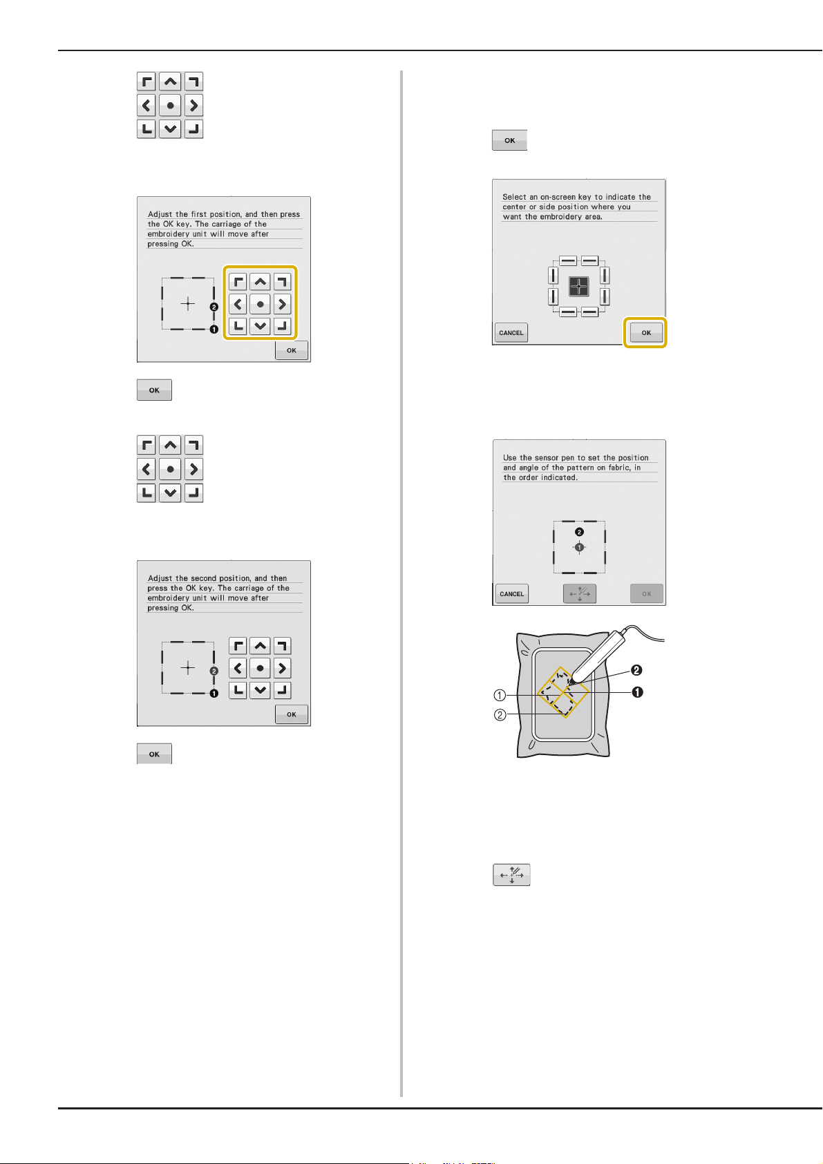
USING SENSOR FUNCTIONS IN “EMBROIDERY”/“EMBROIDERY EDIT” MODE
■ Selecting the Embroidering Position
Press to move the LED pointer
f
by the Pattern Center
(in the “Embroidery Edit” mode only) on
the fabric for adjusting the first position.
Press to apply the setting.
g
Press to move the LED pointer
h
(in the “Embroidery Edit” mode only) on
the fabric for adjusting the second position.
Press in the following screen.
a
With the sensor pen, touch 2 points on the
b
fabric corresponding to the numbers in the
center of the embroidery pattern.
Press to apply the setting.
i
The preview in the embroidery screen is
j
updated according to the specified
embroidering position.
Press the “Start/Stop” button to start
k
embroidering.
B-62
a Center line of the pattern
b Pattern position
→ Specified point number turns into red.
→ If you don’t need to adjust the positions, continue to
g.
step
Press to adjust the positions.
c
Page 65
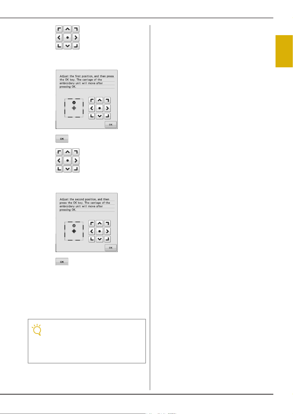
USING SENSOR FUNCTIONS IN “EMBROIDERY”/“EMBROIDERY EDIT” MODE
Note
Press to move the LED pointer
d
(in the “Embroidery Edit” mode only) on
the fabric for adjusting the first position.
Press to apply the setting.
e
B
2
Sensor Functions
Press to move the LED pointer
f
(in the “Embroidery Edit” mode only) on
the fabric for adjusting the second position.
Press to apply the setting.
g
The preview in the embroidery screen is
h
updated according to the specified
embroidering position.
Press the “Start/Stop” button to start
i
embroidering.
• When using the sensor pen to specify the
embroidering position, it may not be
possible to exactly specify the desired
location. In this case, move the embroidery
frame to align the center of the pattern with
the location indicated by the LED pointer.
Basic operations B-63
Page 66

USING SENSOR FUNCTIONS IN “EMBROIDERY”/“EMBROIDERY EDIT” MODE
B-64
Page 67

Embroidering
This section provides instruction to embroider designs with this machine.
Page number starts with “E” in this section.
Before starting embroidery work, refer to “BEFORE EMBROIDERING” of “Basic operations”.
The screen display and machine illustration may vary slightly, depending on the countries or regions.
Chapter1 Embroidery .............................................................E-2
Chapter2 Embroidery Edit ....................................................E-56
Chapter3 How to Create Bobbin Work (Embroidery)........... E-86
Page 68

E Embroidering
Chapter 1
Embroidery
SELECTING PATTERNS..............................................3
■ Copyright Information .............................................................. 3
Selecting Embroidery Patterns/Baby Lock “Exclusives”/Floral
Alphabet/Bobbin Work Patterns .................................................4
Selecting Character Patterns.......................................................5
Selecting Frame Patterns............................................................. 7
Selecting Patterns from Embroidery Cards..................................7
■ About Embroidery Card Reader (Sold Separately) and USB Card
Writer Module*.......................................................................... 7
■ About Embroidery Cards (Sold Separately) ............................... 7
Selecting Patterns from USB Media/Computer ...........................8
VIEWING THE EMBROIDERING SCREEN ................. 9
■ Key Functions........................................................................... 10
PREPARING THE FABRIC ........................................11
Attaching Iron-on Stabilizers (Backing) to the Fabric ...............11
Hooping the Fabric in the Embroidery Frame ..........................13
■ Types of Embroidery Frames .................................................... 13
■ Inserting the Fabric .................................................................. 14
■ Using the Embroidery Sheet ....................................................15
Embroidering Small Fabrics or Fabric Edges ............................16
■ Embroidering Small Fabrics...................................................... 16
■ Embroidering Edges or Corners................................................ 16
■ Embroidering Ribbons or Tape................................................. 16
ATTACHING THE EMBROIDERY FRAME................17
■ Removing the Embroidery Frame ............................................. 17
CONFIRMING THE PATTERN POSITION ............... 19
Checking the Pattern Position ..................................................19
Previewing the Completed Pattern ..........................................20
■ Frame sizes displayed on screen............................................... 20
SEWING AN EMBROIDERY PATTERN..................... 21
Embroidering Attractive Finishes ..............................................21
■ Embroidery Needle Plate Cover .............................................. 22
Sewing Embroidery Patterns .....................................................22
Sewing Embroidery Patterns Which Use Appliqué ................... 23
ADJUSTMENTS DURING THE EMBROIDERY PROCESS
If the Bobbin Runs Out of Thread ............................................ 26
If the Thread Breaks During Sewing ......................................... 27
Restarting from the Beginning .................................................. 28
Resuming Embroidery After Turning Off the Power.................. 28
.....26
MAKING EMBROIDERY ADJUSTMENTS.................30
Adjusting Thread Tension .........................................................30
■ Correct Thread Tension ...........................................................30
■ Upper Thread is Too Tight ....................................................... 30
■ Upper Thread is Too Loose ...................................................... 30
Adjusting the Bobbin Case (with No Color on the Screw) ........31
■ Correct Tension .......................................................................31
■ Bobbin Thread is Too Loose ..................................................... 31
■ Bobbin Thread is Too Tight ...................................................... 32
Using the Automatic Thread Cutting Function
(END COLOR TRIM)................................................................. 32
Using the Thread Trimming Function (JUMP STITCH TRIM) ....32
■ Selecting the Length of Jump Stitch Not to Trim...................... 33
Adjusting the Embroidery Speed ...............................................33
Changing the Thread Color Display ......................................... 34
Changing the “Embroidery Frame Display”.............................. 35
REVISING THE PATTERN ........................................36
Moving the Pattern................................................................... 36
Aligning the Pattern and the Needle ........................................ 36
Changing the Size of the Pattern .............................................. 37
Rotating the Pattern ................................................................. 38
Creating a Horizontal Mirror Image ........................................ 39
Enlarging the Editing Screen..................................................... 39
Changing the Density (Alphabet Character and Frame
Patterns Only) ......................................................................... 40
Changing the Colors of Alphabet Character Patterns .............. 40
Embroidering Linked Characters .............................................. 41
Uninterrupted Embroidering
(Monochrome - Using a Single Color) ...................................... 43
USING THE MEMORY FUNCTION......................... 44
Embroidery Data Precautions................................................... 44
■ Types of Embroidery Data that can be Used.............................44
■ Types of USB Devices/Media that can be Used ........................44
■ Computers and Operating Systems with the Following
Specifications can be Used.......................................................45
■
Precautions on Using the Computer to Create and Save Data
■ Tajima (.dst) Embroidery Data..................................................45
Saving Embroidery Patterns in the Machine’s Memory ............ 46
■ If the Memory is Full.................................................................46
Saving Embroidery Patterns to USB Media............................... 47
Saving Embroidery Patterns in the Computer........................... 48
Retrieving Patterns from the Machine’s Memory .................... 49
Recalling from USB Media ....................................................... 50
Recalling from the Computer ................................................... 51
.......45
EMBROIDERY APPLICATIONS................................52
Using a Frame Pattern to Make an Appliqué (1)....................... 52
Using a Frame Pattern to Make an Appliqué (2)....................... 53
Sewing Split Embroidery Patterns............................................. 54
Page 69

SELECTING PATTERNS
a
c
g
b
d
i
e
j
h
f
Memo
SELECTING PATTERNS
■ Copyright Information
The patterns stored in the machine and embroidery cards are intended for private use only. Any public or
commercial use of copyrighted patterns is an infringement of copyright law and is strictly prohibited.
There are many character and decorative embroidery patterns stored in the machine’s memory (see the “Quick
Reference Guide” for a full summary of patterns in the machine’s memory). You can also use patterns from the
embroidery cards (sold separately).
Once the machine has finished the initialization and the carriage has moved to the start position, the pattern type
selection screen will display.
If another screen is displayed, press , then Embroidery ( or ) to display the screen below.
There are 6 categories of patterns in this machine.
E
1
Embroidery
a Baby Lock “Exclusives”
b Embroidery pattern
c Floral alphabet patterns
d Frame patterns
e Character patterns
f Bobbin work patterns (see page E-92)
g Patterns saved in the machine’s memory (see
page E-49)
h Patterns saved in USB media (see page E-50)
i Patterns saved on the computer (see page E-51)
j Press this key to position the embroidery unit for
storage
• A key that appears stacked, such as
and , indicates that
there are sub-categories, which must be
selected before a pattern selection screen
appears.
Embroidering E-3
Page 70
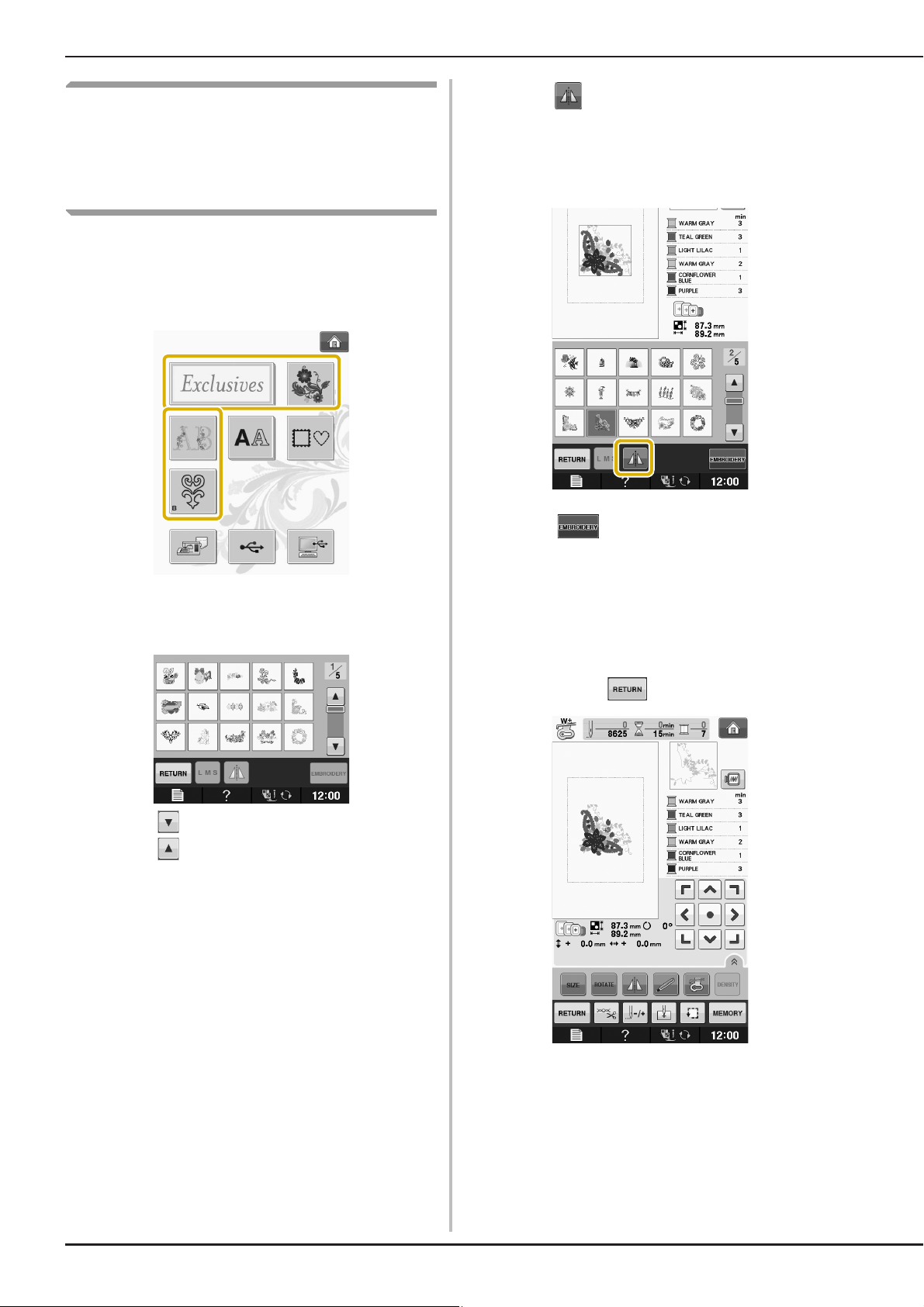
SELECTING PATTERNS
Selecting Embroidery
Patterns/Baby Lock
“Exclusives”/Floral
Alphabet/Bobbin Work Patterns
Touch the key of the category of the pattern
a
you want to embroider.
* Refer to “CREATING BOBBIN WORK” on page E-92
about the bobbin work patterns.
Press to create a mirror image of the
c
pattern as needed.
* If a mistake has been made when selecting the
pattern, press the key of the pattern you want to
embroider and the new selection appears.
Press .
d
→ The embroidery screen is displayed.
Press the key of the pattern you want to
b
embroider.
* Press to view the next page.
* Press to view the previous page.
→ The selected pattern is displayed.
Proceed to “VIEWING THE
e
EMBROIDERING SCREEN” on page E-9 to
embroider the pattern.
* To return to the previous screen to select another
pattern, press .
E-4
Page 71

Selecting Character Patterns
Memo
Example: Entering “We Fly”.
Press .
a
Press the key of the font you want to
b
embroider.
SELECTING PATTERNS
* If you want to change the size of a character, select
the character and then press to change the
size. The size changes each time you press the key,
from large to medium to small.
* If you make a mistake, press to erase the
mistake.
* If the pattern is too small to see clearly, you can use
the key to check it.
Press and enter “e”.
e
E
1
Embroidery
Press to change the selection screens.
c
• If you continue adding characters after
changing the size, the new characters will
be entered in the new size.
• You cannot change the size of the entered
characters after combining character stitch
patterns.
Press and then enter “W”.
d
Press to enter a space.
f
Embroidering E-5
Page 72
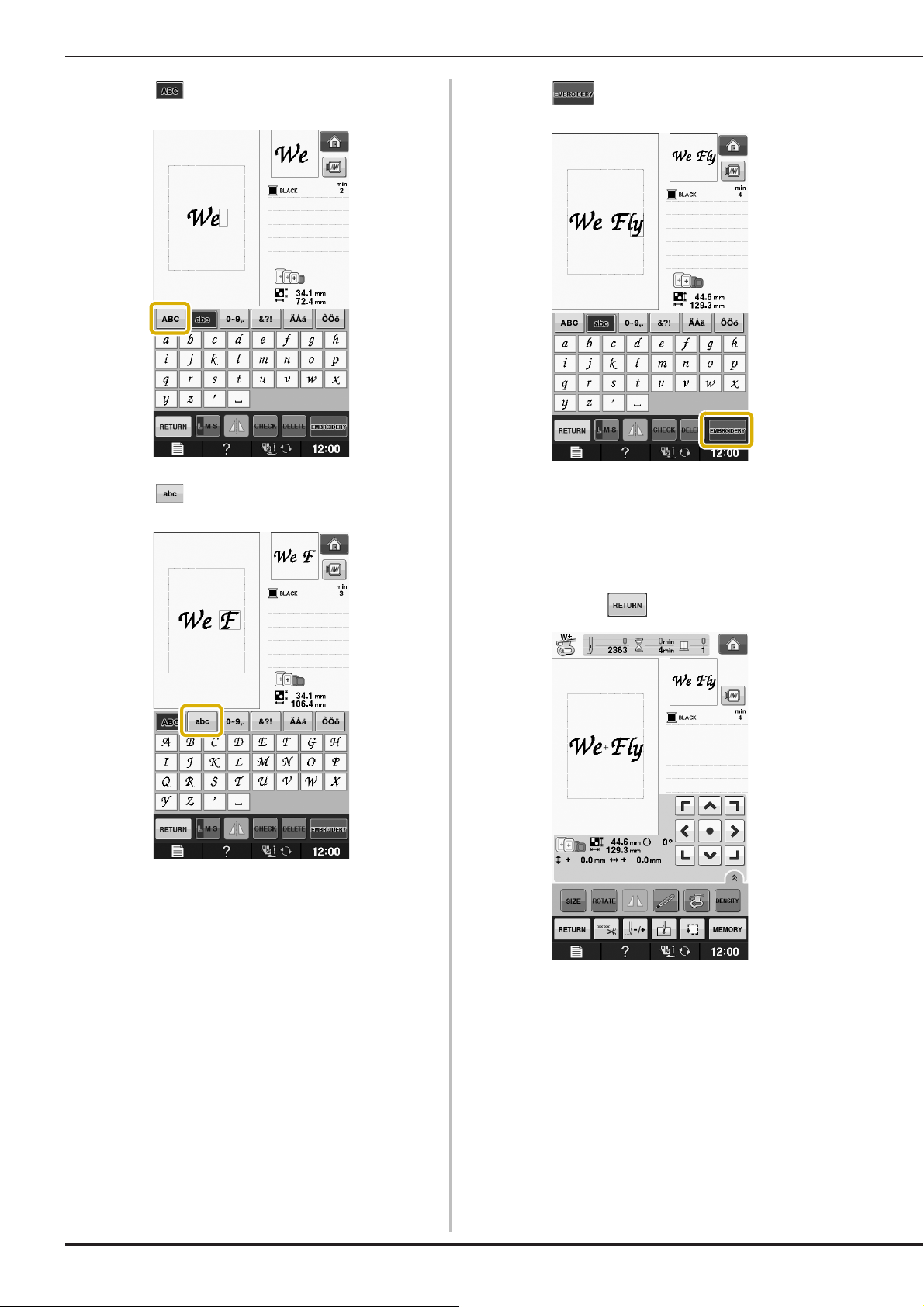
SELECTING PATTERNS
Press again and enter “F”.
g
Press and then enter “ly”.
h
Press .
i
→ The embroidery screen is displayed.
Proceed to “VIEWING THE
j
EMBROIDERING SCREEN” on page E-9 to
embroider the pattern.
* To return to the previous screen to select another
pattern, press .
E-6
Page 73

Selecting Frame Patterns
a
b
Note
Press .
a
SELECTING PATTERNS
Proceed to “VIEWING THE
e
EMBROIDERING SCREEN” on page E-9 to
embroider the pattern.
* To return to the previous screen to select another
pattern, press .
E
1
Press the key of the frame shape you want
b
to embroider in the top part of the screen.
a Frame shapes
b Frame patterns
→ Various frame patterns are displayed at the bottom
part of the screen.
Press the key of the frame pattern you want
c
to embroider.
* If you make a mistake selecting the pattern, press the
key of the pattern you want to embroider.
→ The selected pattern is displayed on the screen.
Press .
d
Embroidery
Selecting Patterns from
Embroidery Cards
■ About Embroidery Card Reader
(Sold Separately) and USB Card
Writer Module*
• Use only an embroidery card Reader designed
for this machine. Using an unauthorized
embroidery card Reader may cause your
machine to operate incorrectly.
* If you have purchased the Palette Ver5 or later,
Palette Petite or Palette PTS, you can plug the
included USB card writer module into the machine
as an embroidery card reader, and recall patterns.
→ The embroidery screen is displayed.
• Embroidery patterns cannot be saved from
the machine to an embroidery card inserted
into a connected USB card writer module*.
■ About Embroidery Cards
(Sold Separately)
• Use only embroidery cards manufactured for this
machine. Using unauthorized cards may cause
your machine to operate incorrectly.
• Embroidery cards sold in foreign countries
cannot be used with this machine.
• Store embroidery cards in the hard case.
Embroidering E-7
Page 74

SELECTING PATTERNS
Note
Plug the optional embroidery card
a
Reader/USB card writer module into the
USB port on the machine.
a USB port
b Embroidery card Reader/USB card writer module
Insert the card completely into the card
b
Reader/USB card writer module.
* Insert the embroidery card so that the end with a
printed arrow is facing up.
Press the key of the USB port.
c
→ The patterns on the embroidery card are displayed
on the selection screen.
Follow the steps on page E-4 to select a
d
pattern.
Selecting Patterns from USB
Media/Computer
• Two embroidery USB card Readers/USB
card writer module cannot be used with this
machine at the same time. If two
embroidery USB card Readers/USB card
writer module are inserted, only the
embroidery USB card Reader/USB card
writer module inserted first is detected.
To recall patterns from the computer or USB
media, see pages E-50 to E-51.
E-8
Page 75

VIEWING THE EMBROIDERING SCREEN
Note
b
l
a
c
e
f
j
k
m
h i
g
d
VIEWING THE EMBROIDERING SCREEN
E
1
Embroidery
a Shows the presser foot code.
Attach embroidery foot “W+” for most embroidery projects. When the foot presser symbol is displayed on the
screen, you are able to sew.
b Shows the boundary for embroidering with the extra large frame (30 cm × 18 cm (approx. 12 inches × 7 inches)).
c Shows a preview of the selected pattern.
d Shows the size of the selected pattern.
e Shows the embroidery frames that can be used for the selected pattern. Be sure to use the proper frame (see page
E-13).
f Shows how far the sewing position is from the center (when you move the sewing position).
g Shows the degree of rotation of the pattern.
h Shows how many stitches are in the selected pattern and how many stitches have been sewn so far.
i Shows the time necessary to sew the pattern, and the time already spent sewing the pattern (not including time for
changing and automatically trimming the thread).
j Shows the number of colors in the selected pattern, and the number of the color currently being sewn.
k Shows the part of the embroidery that will be sewn with the first thread color.
l Shows the order for thread color changes and the embroidering time for each thread color.
m Press an arrow key to move the pattern in the direction shown by the arrow. (Press the Center key to return the
pattern to the center of the embroidery area.)
* The displayed time is the approximate time that will be required. The actual embroidering time may be longer than the
displayed time, depending on the embroidery frame that is used. In addition, the amount of time required to change
thread colors is not included.
• There is an explanation of additional key functions on the next page.
Embroidering E-9
Page 76
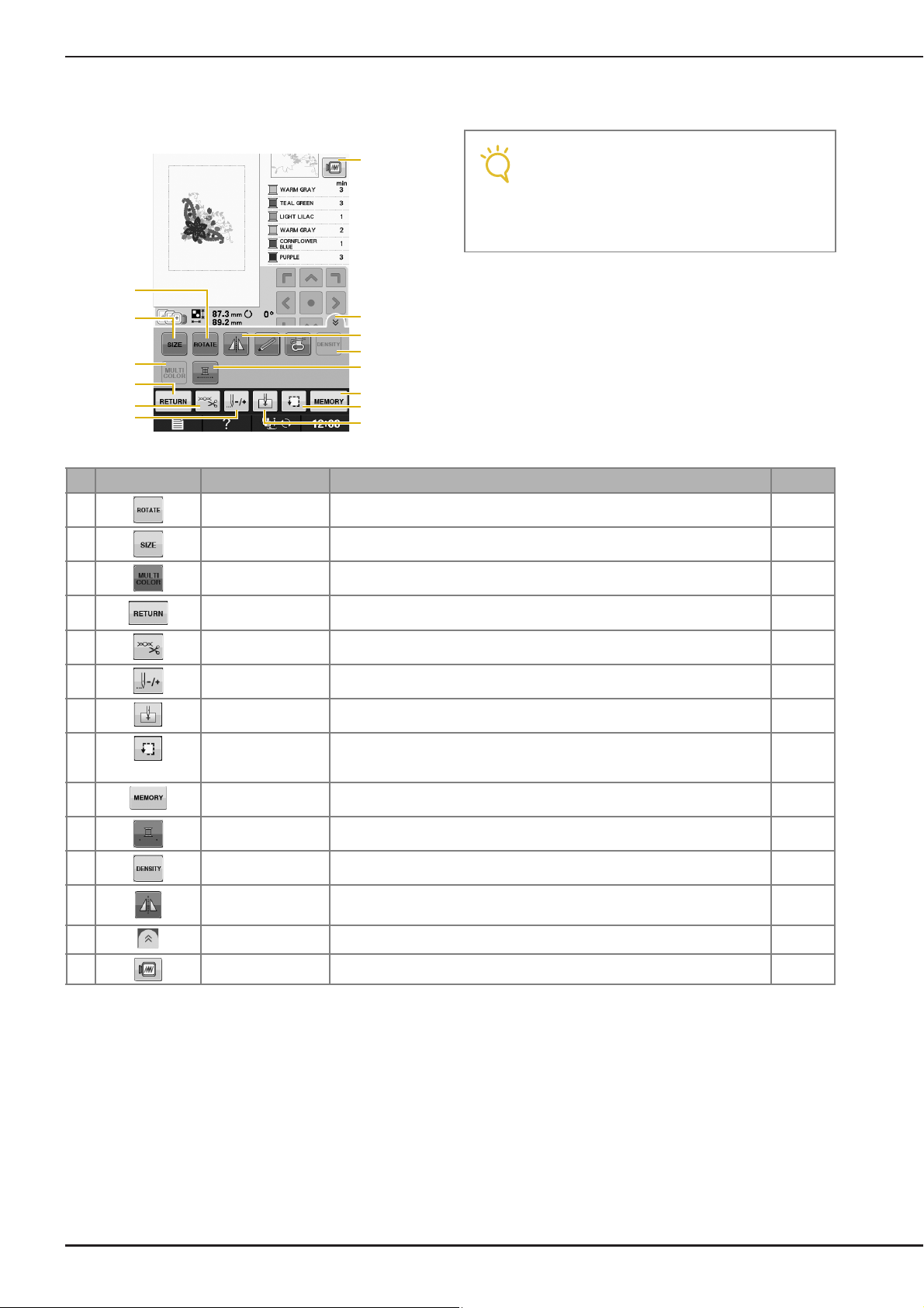
VIEWING THE EMBROIDERING SCREEN
Note
z
p
s
Q
t
v
u
r
n
o
q
y
x
w
■ Key Functions
Using these keys, you can change the size of the pattern, rotate the pattern, etc.
• Some operations or functions are not
available for certain patterns. If the key
display is light gray, you cannot use that
function or operation with the selected
pattern.
No. Display Key Name Explanation Page
n Rotate key Press this key to rotate the pattern. You can rotate a pattern one degree, 10
degrees or 90 degrees at a time.
o Size key Press this key to change the size of the pattern. E-37
E-38
p Multi color key Press this key to change the color of each letter when sewing alphabet
character patterns.
q Return key Press this key to return to the pattern type selection screen. —
r Cut/Tension key Press this key to specify automatic thread cutting, thread trimming or the
s Forward/Back key Press this key to move the needle forward or back in the pattern; useful if the
t Starting point key Press this key to move the needle start position to align the needle with the
u Trial key Press this key to check the position of the pattern.The embroidery frame moves
v Memory key Press this key to save a pattern in the machine’s memory, USB media or a
w Uninterrupted
embroidery key
x Density key Press this key to change the density of alphabet character or frame patterns. E-40
y Horizontal mirror
image key
z Function page key Press this key to show all the keys in this screen. E-40
Q Image key Press this key for a preview of the sewn image. E-20
thread tension. For embroidery, these functions are set automatically.
thread breaks while sewing or if you want to start again from the beginning.
pattern position.
to the desired position so you can check that there is enough space to sew the
pattern.
computer.
Press this key to embroider the selected pattern with a single color. E-43
Press this key to create a horizontal mirror image of the pattern. E-39
E-40
E-32 to
E-33
E-27 to
E-29
E-36
E-19
E-46 to
E-48
E-10
Page 77

PREPARING THE FABRIC
CAUTION
Note
CAUTION
PREPARING THE FABRIC
• Use fabrics with a thickness of less than 3 mm (approx. 1/8 inch). Using fabrics thicker than 3 mm
(approx. 1/8 inch) may cause the needle to break.
• When using layers with thicker batting etc., you can sew more attractive embroidery by adjusting the
embroidery presser foot height in the embroidery settings screen (see below).
• In the case of thick terry cloth towels we recommend that you place a piece of water soluble stabilizer on
the top surface of the towel. This will help to reduce the nap of the toweling and result in more attractive
embroidery.
E
1
Embroidery
• Press . In the “Embroidery Foot
Height” display, use and in the
settings screen. Adjust the presser foot
height for thick or puffy fabrics.
• To increase the space between the presser
foot and the needle plate, set the
embroidery foot height to a larger number,
1.5 mm setting is used for most
embroidery.
Attaching Iron-on Stabilizers
(Backing) to the Fabric
For best results in your embroidery projects,
always use stabilizer material for embroidery.
Follow the package instructions for the stabilizer
being used.
When using fabrics that cannot be ironed (such as
towel or fabrics that have loops which expand
when ironed) or in places where ironing is
difficult, position the stabilizer material under the
fabric without fusing it, then position the fabric
and stabilizer in the embroidery frame, or check
with your authorized retailer for the correct
stabilizer to use.
• Always use a stabilizer material for embroidery
when sewing stretch fabrics, lightweight
fabrics, fabrics with a coarse weave, or fabrics
which cause pattern shrinkage. Otherwise, the
needle may break and cause injury. Not using
a stabilizer material may result in a poor finish
to your project.
Use a piece of stabilizer which is larger
a
than the embroidery frame being used.
a Size of the embroidery frame
b Iron-on stabilizer (backing)
Embroidering E-11
Page 78

PREPARING THE FABRIC
Memo
Iron the iron-on stabilizer material to the
b
wrong side of the fabric.
a Fusible side of stabilizer
b Fabric (wrong side)
• When embroidering on thin fabrics such as
organdy or lawn, or on napped fabrics such
as towel or corduroy, use water soluble
stabilizer (sold separately) for best results.
The water soluble stabilizer material will
dissolve completely in water, giving the
project a more attractive finish.
E-12
Page 79

Hooping the Fabric in the Embroidery Frame
CAUTION
ab
PREPARING THE FABRIC
■ Types of Embroidery Frames
The types and numbers of supplied embroidery frames differ depending on the country or region.
Extra Large Large
Embroidery field
300 mm × 180 mm
(approx. 12 inches × 7 inches)
Use when embroidering connected or combined characters or
patterns, or when embroidering large patterns.
Other optional embroidery frames can be used. When choosing frames that do not appear on the screen, be sure
to check the design size of the embroidery field of the optional frame. Check with your authorized retailer for
frame compatibility.
Select a frame that matches the pattern size. Included frame options are displayed on the LCD.
Use when embroidering patterns between 100 mm × 100 mm
(approx. 4 inches × 4 inches) and
180 mm × 130 mm (approx. 7 inches × 5 inches).
Embroidery field
180 mm × 130 mm
(approx. 7 inches × 5 inches)
E
1
Embroidery
a Highlighted: Can be used
b Shaded: Cannot be used
• If you use a frame that is too small, the presser foot may strike the frame during sewing and cause injury.
Embroidering E-13
Page 80
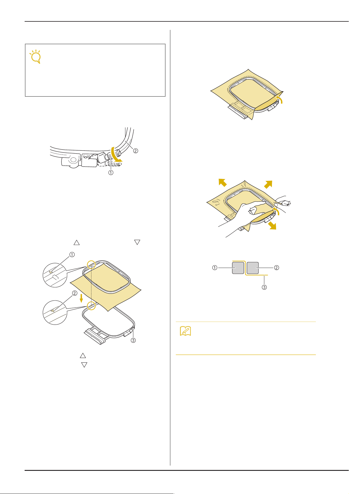
PREPARING THE FABRIC
Note
Memo
■ Inserting the Fabric
• If the fabric is not securely held in the
embroidery frame, the embroidery design
will sew out poorly. Insert the fabric on a
level surface, and gently stretch the fabric
taut in the frame. Follow the steps below to
insert the fabric correctly.
Lift-up and loosen the frame adjustment
a
screw and remove the inner frame.
a Frame adjustment screw
b Inner frame
Slightly tighten the frame adjustment screw,
c
and then remove the slack in the fabric by
pulling on the edges and corners. Do not
loosen the screw.
Gently stretch the fabric taut, and tighten
d
the frame adjustment screw to keep the
fabric from loosening after stretching.
* After stretching the fabric, make sure the fabric is
taut.
Lay the fabric right side up on top of the
b
outer frame.
Re-insert the inner frame making sure to align the
inner frame’s with the outer frame’s .
a Inner frame’s
b Outer frame’s
c Frame adjustment screw
* Make sure the inside and outside frames are even
before you start embroidering.
a Outer frame
b Inner frame
c Fabric
• Stretch the fabric from all four corners and
all four edges. While stretching the fabric,
tighten the frame adjustment screw.
E-14
Page 81
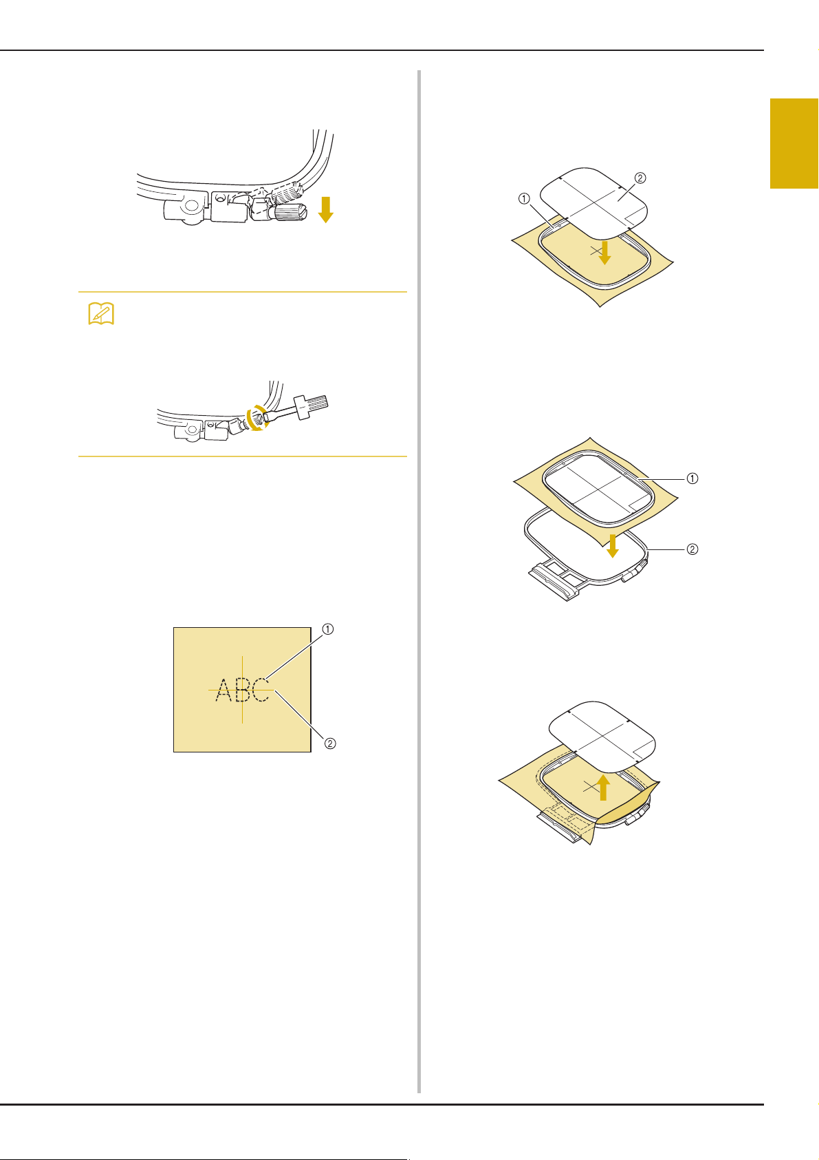
PREPARING THE FABRIC
Memo
Return the frame adjustment screw to its
e
initial position.
• You can use the included screwdriver when
you loosen or tighten the frame adjustment
screw.
Place the embroidery sheet on the inner
b
frame. Align the guide lines on the
embroidery sheet with the mark you made
on the fabric.
a Inner frame
b Guide line
Gently stretch the fabric so there are no
c
folds or wrinkles, and press the inner frame
into the outer frame.
E
1
Embroidery
■ Using the Embroidery Sheet
When you want to embroider the pattern in a
particular place, use the embroidery sheet with the
frame.
With a chalk pencil, mark the area of the
a
fabric you want to embroider.
a Embroidery pattern
b Mark
a Inner frame
b Outer frame
Remove the embroidery sheet.
d
Embroidering E-15
Page 82

PREPARING THE FABRIC
Embroidering Small Fabrics or
Fabric Edges
Use an embroidery stabilizer to provide extra
support. After embroidering, remove the stabilizer
carefully. Attach the stabilizer as shown in the
following examples. We recommend using a
stabilizer for embroidery.
■ Embroidering Small Fabrics
Use a temporary spray adhesive to adhere the small
piece of fabric to the larger piece in the frame.
If you do not wish to use a temporary spray
adhesive, attach the stabilizer with a basting stitch.
■ Embroidering Ribbons or Tape
Secure with double-sided tape or a temporary spray
adhesive.
a Ribbon or tape
b Stabilizer
a Fabric
b Stabilizer
■ Embroidering Edges or Corners
Use a temporary spray adhesive to adhere the small
piece of fabric to the larger piece in the frame.
If you do not wish to use a temporary spray
adhesive, attach the stabilizer with a basting stitch.
a Fabric
b Stabilizer
E-16
Page 83

ATTACHING THE EMBROIDERY FRAME
Note
CAUTION
ATTACHING THE EMBROIDERY FRAME
E
• Wind and insert the bobbin before attaching the embroidery frame.
Press the “Presser Foot Lifter” button to
a
raise the presser foot.
Align the embroidery frame guide with the
b
right edge of the embroidery frame holder.
a Embroidery frame holder
b Embroidery frame guide
Slide the embroidery frame into the holder,
c
making sure to align the embroidery frame’s
with the holder’s .
Lower the frame-securing lever to be level
d
with the frame to secure the embroidery
frame in the embroidery frame holder.
a Frame-securing lever
• If the frame-securing lever is not lowered, the
following message appears. You cannot start
sewing until you lower the frame-securing
lever.
1
Embroidery
a Arrow mark
■ Removing the Embroidery Frame
Raise the frame-securing lever.
a
Embroidering E-17
Page 84

ATTACHING THE EMBROIDERY FRAME
Pull the embroidery frame toward you.
b
E-18
Page 85
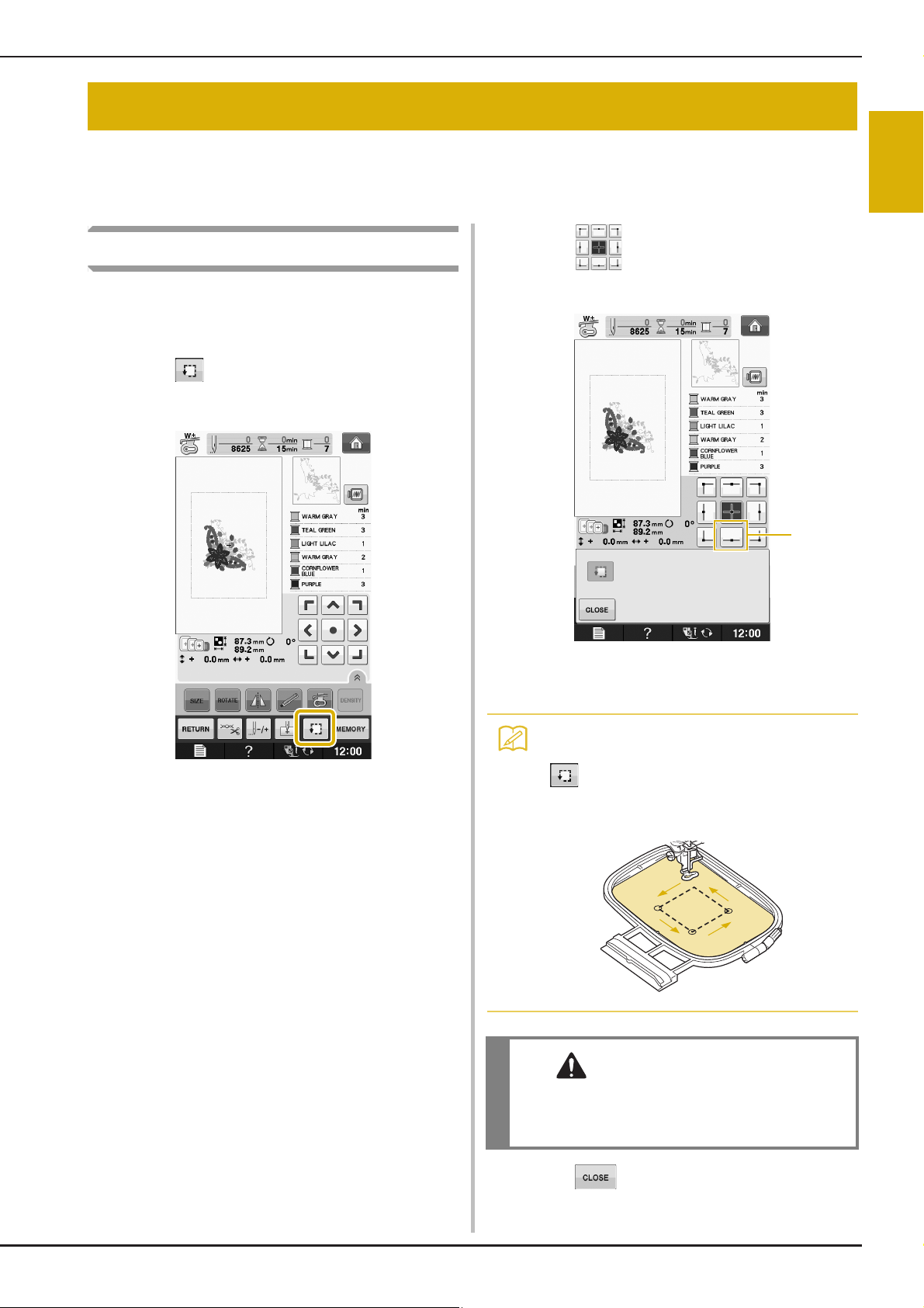
CONFIRMING THE PATTERN POSITION
Memo
CAUTION
a
CONFIRMING THE PATTERN POSITION
The pattern is normally positioned in the center of the embroidery frame. If the pattern needs to be
repositioned for better placement on the garment, you can check the layout before starting embroidery.
Checking the Pattern Position
The embroidery frame moves and shows the
pattern position. Watch the frame closely to make
sure the pattern will be sewn in the right place.
Press .
a
From , press the key for the position
b
that you want to check.
E
1
Embroidery
→ The following screen is displayed.
a Selected position
→ The needle will move to the selected position on the
pattern.
• To see the entire embroidering area, press
. The embroidery frame moves and
shows the embroidery area.
• Make sure the needle is up when the
embroidery frame is moving. If the needle is
down, it could break and result in injury.
Press .
c
Embroidering E-19
Page 86
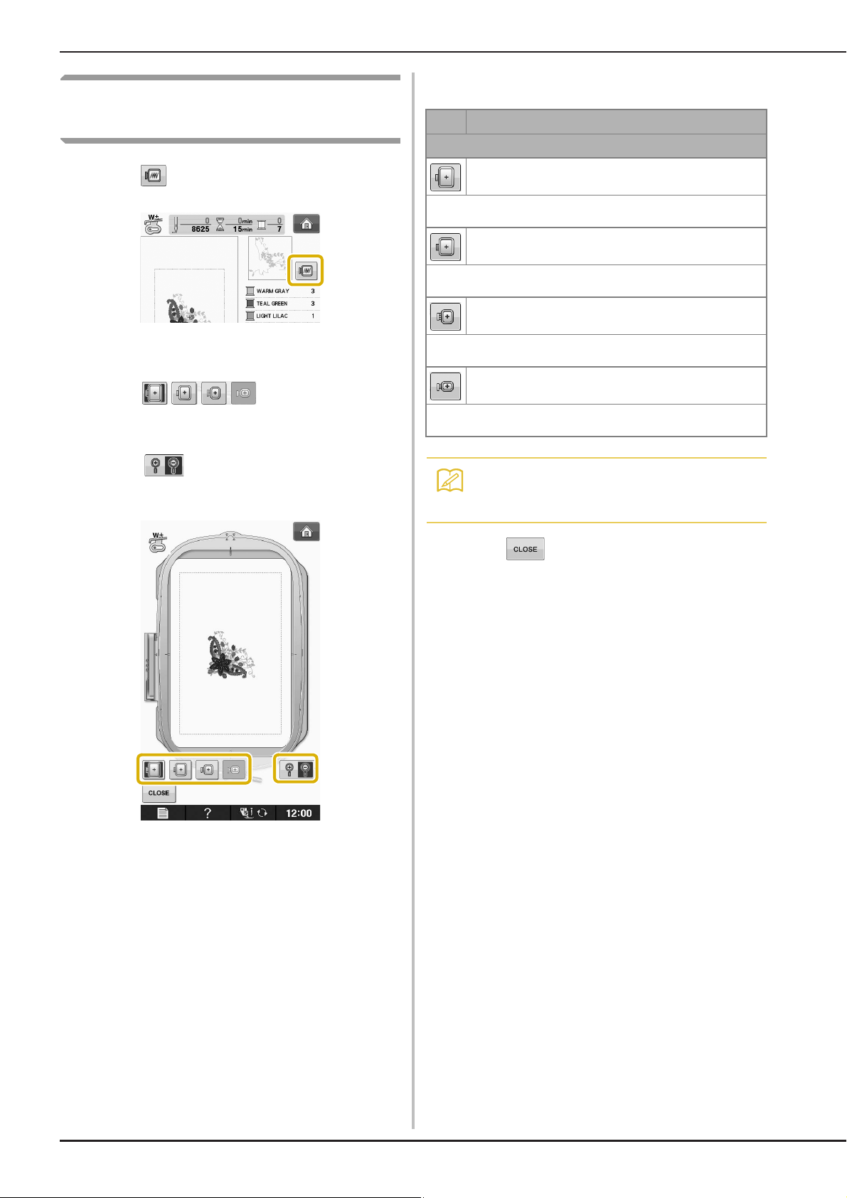
CONFIRMING THE PATTERN POSITION
Memo
Previewing the Completed
Pattern
Press .
a
■ Frame sizes displayed on screen
Icon Name
Embroidering area
Extra large embroidery frame
H 300 mm × W 180 mm
(H 12 inches × W 7 inches)
Large embroidery frame
H 180 mm × W 130 mm
(H 7 inches × W 5 inches)
Medium embroidery frame (optional)
→ An image of the pattern as it will be embroidered
appears.
Press to select the frame
b
used in the preview.
* Frames displayed in light gray cannot be selected.
* Press to enlarge the image of the pattern.
* The pattern can be sewn as it appears in the
following display.
H 100 mm × W 100 mm
(H 4 inches × W 4 inches)
Small embroidery frame (optional)
H 20 mm × W 60 mm
(H 1 inch × W 2-1/2 inches)
• You can begin sewing from this screen by
pressing the “Start/Stop” button.
Press to return to the original screen.
a
E-20
Page 87

SEWING AN EMBROIDERY PATTERN
Memo
CAUTION
Note
SEWING AN EMBROIDERY PATTERN
Embroidering Attractive Finishes
There are many factors that go into beautiful embroidery. Using the appropriate stabilizer (see page E-11)
and hooping the fabric in the frame (see page E-13) are two important factors mentioned earlier. Another
important point is the appropriateness of the needle and thread being used. See the explanation of threads
below.
E
1
Embroidery
Thread Upper thread Use embroidery thread intended for use with this machine.
Bobbin thread Use embroidery bobbin thread intended for use with this machine.
• If you use threads other than those listed above, the embroidery may not sew out correctly.
Other embroidery threads may not yield optimum results.
Included bobbin case varies depending on the model of machine. See explanation below to understand
the different bobbin cases.
Bobbin case (recommended for
sewing and for embroidering with
included 60 weight bobbin thread)
a Standard bobbin case
(green marking on the screw)
Bobbin case (for prewound or other
embroidery bobbin threads)
Standard bobbin case originally installed in the machine has a green marking on the screw. We
recommend using the included embroidery bobbin thread with this bobbin case. Do not adjust the
tension screw on this bobbin case with the green marked screw.
The bobbin case with no color on the screw is set with tighter tension for embroidery with different
weights of bobbin threads and a variety of embroidery techniques. This bobbin case is identified
with a dark colored mark on the inside of the bobbin cavity. The tension screw on this case can be
adjusted if necessary (see page E-31).
a Bobbin case (no color on the
screw)
See “Cleaning the Race” of “Appendix” for how to remove the bobbin case.
• When embroidering on large garments (especially jackets or other heavy fabrics), do not let the fabric
hang over the table. Otherwise, the embroidery unit cannot move freely and the embroidery frame may
strike the needle, causing the needle to bend or break and possibly cause injury.
Place the fabric so that it does not hang off the table or hold the fabric to keep it from dragging.
• Before embroidering, check that there is enough thread in the bobbin. If you start to sew your
embroidery project without enough thread in the bobbin, you will need to rewind the bobbin in the
middle of the embroidery pattern.
• Do not leave objects in the range of motion of the embroidery frame. The frame may strike the object
and cause a poor finish to the embroidery pattern.
• When embroidering on large garments (especially jackets or other heavy fabrics), do not let the fabric
hang over the table. Otherwise, the embroidery unit cannot move freely, and the pattern may not turn
out as planned.
Embroidering E-21
Page 88

SEWING AN EMBROIDERY PATTERN
CAUTION
Note
Memo
b
a
■ Embroidery Needle Plate Cover
Under some conditions, based on the type of fabric,
stabilizer, or thread being used, there may be some
looping in the upper thread. In this case, attach the
included embroidery needle plate cover to the
needle plate. Attach the cover by inserting the two
projections on the underside of the cover into the
notches on the needle plate as shown below.
a Groove
b Projection
c Notch
To remove the embroidery needle plate cover, place
your fingernail in the groove and lift the plate out.
Sewing Embroidery Patterns
Example:
• Push the embroidery needle plate cover as far
as possible to attach it. If the embroidery
needle plate cover is not securely attached, it
may cause the needle to break.
• Do not use the embroidery needle plate
cover for any applications other than
embroidery.
a Embroidery color order
b Cursor
• The [+] cursor moves over the pattern,
showing which part of the pattern is being
sewn.
Thread the machine with thread for the first
a
color, pass the thread through the hole in
embroidery foot, pull out some thread to
give it some slack, and then lightly hold the
end of the thread in your left hand.
E-22
Page 89
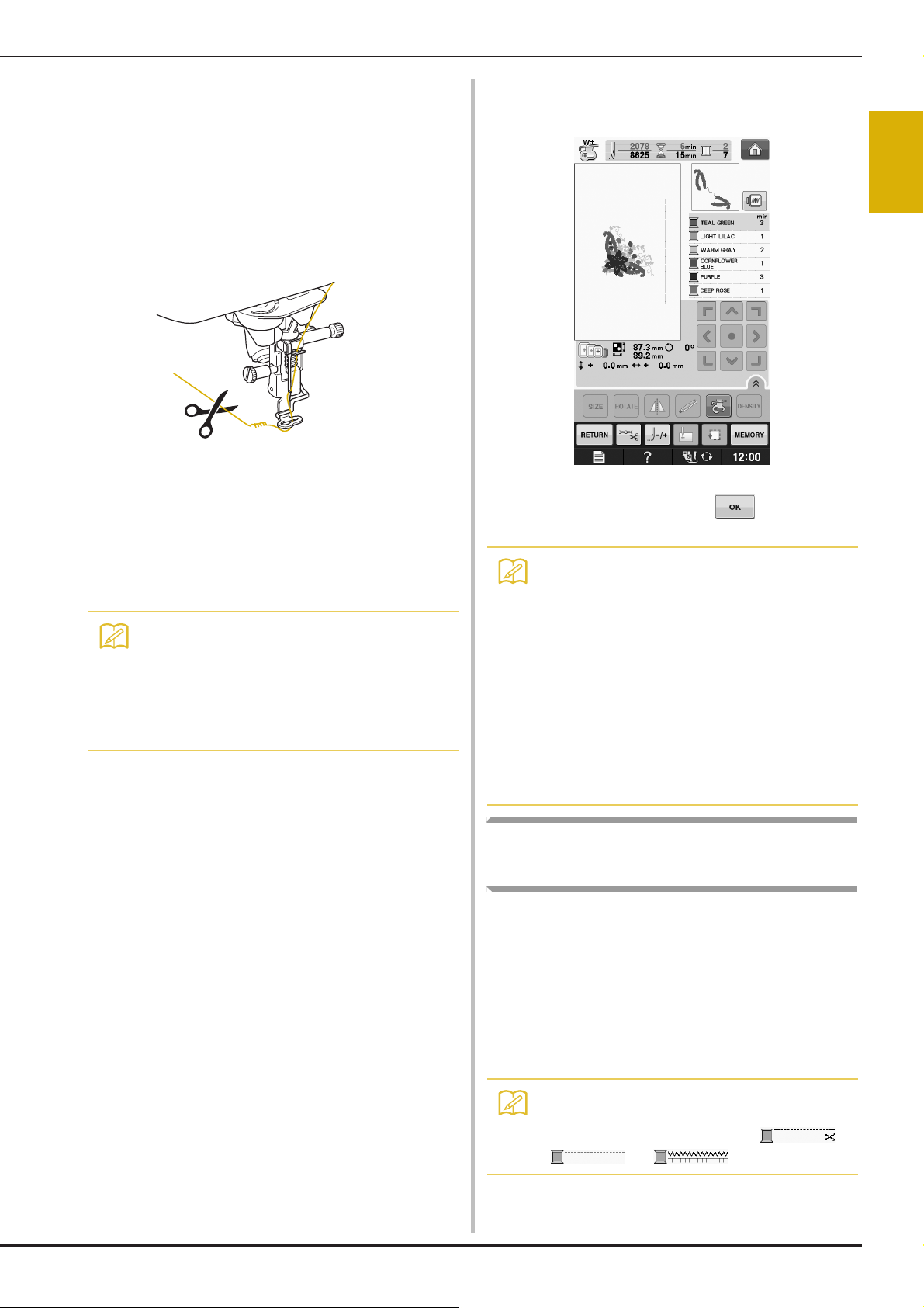
SEWING AN EMBROIDERY PATTERN
Memo
Memo
Memo
Lower the presser foot, then press the
b
“Start/Stop” button to start embroidering.
After 5-6 stitches, press the “Start/Stop”
button again to stop the machine.
Trim the excess thread at the end of the
c
seam. If the end of the seam is under the
presser foot, raise the presser foot, then
trim the excess thread.
Press the “Start/Stop” button to start
d
embroidering.
→ When the first color is completely sewn, the machine
will automatically trim the threads and stop. The
presser foot will then automatically be raised.
On the embroidery color order display, the next
color will move to the top.
• If there is thread left over from the beginning
of sewing, it may be sewn over as you
continue embroidering the pattern, making
it very difficult to deal with the thread after
the pattern is finished. Trim the threads at
the beginning of each thread change.
Remove the thread for the first color from
e
the machine. Thread the machine with the
next color.
Repeat the same steps for embroidering the
f
remaining colors.
→ When the last color is sewn, “Finished sewing” will
appear on the display. Press , and the display
will return to the original screen.
• The Thread Trimming Function is originally
set to trim excess thread jumps (threads
linking parts of the pattern, etc.). Depending
on the type of thread and fabric that are
used, an end of upper thread may remain
on the surface of the fabric at the beginning
of the stitching. After embroidering is
finished, cut off this excess thread.
If the setting has been turned off, trim the
excess thread jumps using scissors after
the pattern is finished.
See page E-32 for information on the thread
trimming function.
E
1
Embroidery
Sewing Embroidery Patterns
Which Use Appliqué
There are some patterns which call for an appliqué
inside the pattern. Prepare the base fabric and the
appliqué fabric (appliqué piece).
When sewing an embroidery pattern with an
appliqué, the color sewing order display shows
“APPLIQUE MATERIAL”, “APPLIQUE POSITION”,
“APPLIQUE”, and then the sewing order of the
colors around the appliqué.
• Depending on the thread color display
setting, the display may show ,
, or .
Embroidering E-23
Page 90

SEWING AN EMBROIDERY PATTERN
Memo
Memo
Attach an iron-on stabilizer to the wrong
a
side of the appliqué material.
a Appliqué material (cotton, felt, etc.)
b Iron-on stabilizer
Place the appliqué material into the
b
embroidery frame, and then press the
“Start/Stop” button to sew the outline of
the appliqué.
Place the base material into the embroidery
d
frame.
a Base material
Press the “Start/Stop” button to sew the
e
position of the appliqué.
* Use the same thread color you plan to use when
attaching the appliqué in step g.
a Outline of appliqué
b Appliqué material
• The embroidery procedure is the same as
the basic procedure explained on
page E-22.
→ The machine will sew around the outline of the
appliqué pieces and will then stop.
Remove the appliqué material from the
c
embroidery frame, and then cut carefully
along the stitching. After cutting, remove all
of the stitching thread carefully.
* Carefully cut out the pattern on the outline you just
sewed. Do not cut inside the stitching line, as the
appliqué fabric will not be caught by the appliqué
stitch.
a Position of appliqué
b Base material
→ The machine will sew around the position of the
appliqué and will then stop.
Apply a thin layer of adhesive or spray
f
adhesive to the back of the appliqué piece
and attach it to the appliqué position so that
it follows the seam of the outline.
• If the appliqué material is a lightweight
fabric, you may want to use a fusible web
on the back to stabilize the fabric and for
appliqué placement. Fuse appliqué in place
with an iron.
Do not remove fabric from the frame to iron
the appliqué material.
E-24
Page 91

Press the “Start/Stop” button.
Memo
Memo
g
• Some patterns may not show all three
appliqué steps. Sometimes the
“APPLIQUE” step will be shown as a color.
→ The appliqué will then be completed.
Change the upper thread and then carry out
h
the rest of the embroidering.
SEWING AN EMBROIDERY PATTERN
E
1
Embroidery
• Some glue may get onto the presser foot,
needle, and needle plate at this time. Finish
embroidering the appliqué pattern and then
clean away the glue.
• For best sewing results clip all threads
between color steps.
Embroidering E-25
Page 92

ADJUSTMENTS DURING THE EMBROIDERY PROCESS
Note
Note
ADJUSTMENTS DURING THE EMBROIDERY PROCESS
• Be careful not to bump the embroidery unit carriage or the presser foot when removing or attaching
the embroidery frame. Otherwise, the pattern will not embroider correctly.
Unlock the frame-securing lever and
If the Bobbin Runs Out of Thread
When the bobbin begins to run out of thread
during embroidering, the machine will stop and
the message below will appear. Press and
follow the directions below to rethread the lower
threading. If very little sewing remains, you can
embroider 10 final stitches without rethreading the
machine by pressing . The machine will stop
after sewing the 10 stitches.
b
remove the embroidery frame.
* Be careful not to apply strong force to the fabric at
this time. Otherwise, the fabric may loosen in the
frame.
a
• If “Upper and Bobbin Thread Sensor” in the
settings screen of the machine setting
mode is set to “OFF”, the message shown
above does not appear.
Press .
Insert a wound bobbin into the machine
c
(see “Setting the Bobbin” of “Basic
operations”).
Press .
d
E-26
→ After the thread is automatically cut, the carriage
will move.
→ The carriage will return to its original position.
Attach the embroidery frame.
e
To return to the spot in the pattern where
f
you stopped sewing, follow steps
through
f in the next section.
c
Page 93

If the Thread Breaks During
Sewing
Press the “Start/Stop” button to stop the
a
machine.
If the upper thread is broken, redo the
b
upper threading. If the bobbin thread is
broken, press and follow the
directions in steps
previous section to reset the bobbin.
Press .
c
a through e from the
ADJUSTMENTS DURING THE EMBROIDERY PROCESS
Press , , , or to move
d
the needle back the correct number of
stitches before the spot where the thread
broke.
* If you cannot move back to the spot where the
thread broke, press to select the color and
move to the beginning position of that color, then
use , , , or to move ahead
to slightly before where the thread broke.
E
1
Embroidery
Press to return to the original screen.
e
Press the “Presser Foot Lifter” button to
f
lower the presser foot, and press the
“Start/Stop” button to continue sewing.
Embroidering E-27
Page 94

ADJUSTMENTS DURING THE EMBROIDERY PROCESS
Memo
Note
a
Restarting from the Beginning
Press .
a
Resuming Embroidery After
Turning Off the Power
The current color and stitch number are saved
when embroidery is stopped. The next time the
machine is turned on, you have the option to
continue or delete the pattern.
• Even if the power goes out in the middle of
embroidery, the machine returns to the
point where embroidery was stopped when
the machine is turned on again.
Press .
b
→ The embroidery frame moves, returning the needle
to the pattern’s beginning position.
Press the “Presser Foot Lifter” button to
c
lower the presser foot and start sewing.
a Current stitch number when embroidery was
stopped
• Do not remove the embroidery unit or the
memory will no longer remember your
design.
Turn the main power to ON.
a
Follow the instructions shown on the screen
b
and remove the embroidery frame.
→ The following message will appear.
E-28
Page 95
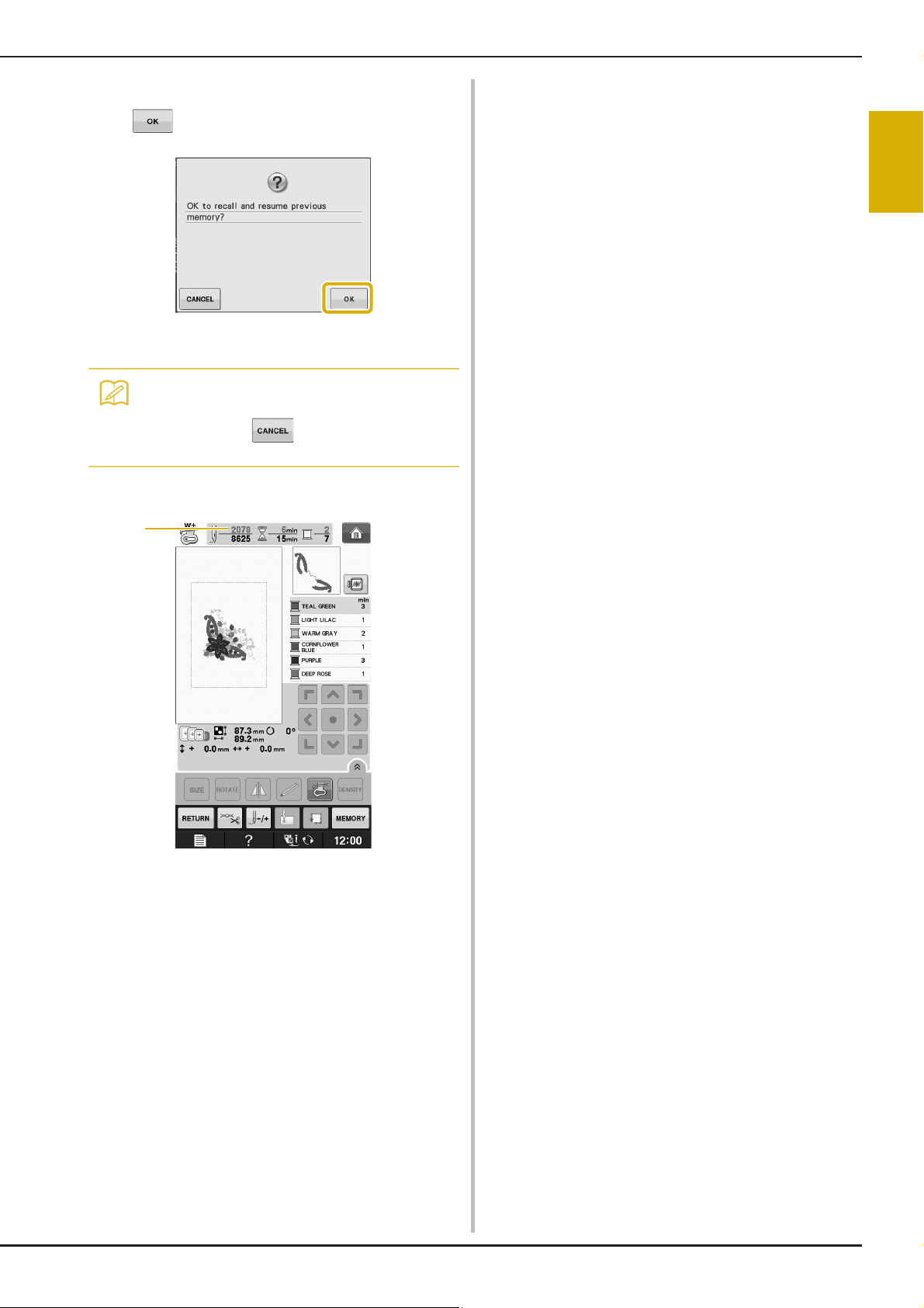
Attach the embroidery frame and press
Memo
a
c
.
→ The previous embroidery screen displayed before
the machine was turned off appears.
• If you want to start a new embroidery
pattern, press so the pattern
selection screen appears.
Continue embroidering.
d
ADJUSTMENTS DURING THE EMBROIDERY PROCESS
E
1
Embroidery
a Stitch number when embroidery is resumed
Embroidering E-29
Page 96

MAKING EMBROIDERY ADJUSTMENTS
Note
Memo
Note
Note
MAKING EMBROIDERY ADJUSTMENTS
Press .
Adjusting Thread Tension
When embroidering, the thread tension should be
set so that the upper thread can slightly be seen on
the wrong side of the fabric.
■ Correct Thread Tension
The pattern can be seen from the wrong side of the
fabric. If the thread tension is not set correctly, the
pattern will not finish well. The fabric may pucker or
the thread may break.
a Right side
b Wrong side
Follow the operations described below to adjust
thread tension according to the situation.
a
• If the thread tension setting is made
extremely weak, the machine may stop
during sewing. This is not the sign of a
malfunction. Increase the thread tension
slightly, and begin sewing again.
• If you turn the main power to OFF or select
a different pattern, the thread tension will
reset to the automatic setting.
• When you retrieve a saved pattern, the
thread tension setting will be the same as
when the pattern was saved.
■ Upper Thread is Too Tight
The tension of the upper thread is too tight, resulting
in the bobbin thread being visible from the right side
of the fabric.
• If the bobbin thread was incorrectly
threaded, the upper thread may be too
tight. In this case, refer to “Setting the
Bobbin” of “Basic operations” and rethread
the bobbin thread.
Press to weaken the upper thread
b
tension. (The tension number will
decrease.)
Press .
c
■ Upper Thread is Too Loose
The tension of the upper thread is too loose,
resulting in a loose upper thread, loose thread locks,
or loops appearing on the right side of the fabric.
• If the upper thread was incorrectly
threaded, the upper thread may be too
loose. In this case, refer to “Upper
Threading” of “Basic operations” and
rethread the upper thread.
E-30
a Right side
b Wrong side
a Right side
b Wrong side
Press .
a
Page 97
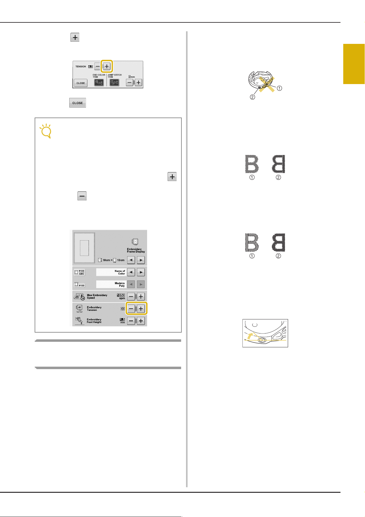
MAKING EMBROIDERY ADJUSTMENTS
Note
Press to tighten the upper thread
b
tension. (The tension number will increase.)
Press .
c
• With “Embroidery Tension” on the setting
screen, the tension of the upper thread can
be adjusted for embroidering. The selected
setting will be applied to all patterns.
When embroidering, if the overall tension of
the upper thread is too tight or too loose,
adjust it from the setting screen. Press
to tighten the upper thread tension and
press to loosen the upper tension. If an
individual embroidery pattern needs
additional fine tuning, refer to “Adjusting
Thread Tension” on page E-30.
To adjust the bobbin tension for embroidery
function, using the bobbin case (with no color on
the screw), turn the slotted-head screw (-) with a
(small) screwdriver.
a Do not turn a phillips screw (+).
b Adjust with a screwdriver (small).
■ Correct Tension
Upper thread slightly appears on the wrong side of
fabric.
a Right side
b Wrong side
■ Bobbin Thread is Too Loose
Bobbin thread appears slightly on the right side of
fabric.
E
1
Embroidery
Adjusting the Bobbin Case (with
No Color on the Screw)
The bobbin case (with no color on the screw) can
be adjusted when bobbin tension changes are
required to accommodate different bobbin
threads. See “Embroidering Attractive Finishes” on
page E-21.
a Right side
b Wrong side
If this occurs, turn the slotted-head screw (-)
clockwise, being careful not to over-tighten the
screw, approximately 30-45 degrees to increase
bobbin tension.
Embroidering E-31
Page 98

MAKING EMBROIDERY ADJUSTMENTS
CAUTION
■ Bobbin Thread is Too Tight
Upper thread on the right side of fabric seems to be
lifting/looping and bobbin thread is not seen on the
wrong side of fabric.
a Right side
b Wrong side
If this occurs, turn the slotted-head screw (-)
counterclockwise, being careful not to over-loosen
the screw, approximately 30-45 degrees to decrease
bobbin tension.
• When adjusting the bobbin case, be sure to
remove the bobbin from the bobbin case.
• DO NOT adjust the position of the phillips (+)
screw on the bobbin case as this may result in
damage to the bobbin case, rendering it
unusable.
• If the slotted-head screw (-) is difficult to turn,
do not use force. Turning the screw too much
or providing force in either (rotational)
direction may cause damage to the bobbin
case. Should damage occur, the bobbin case
may not maintain proper tension.
Press .
a
Press to turn off the automatic thread
b
cutting function.
→ The key will display as
* When one color thread is sewn, the machine will
stop without cutting the thread.
Using the Thread Trimming
Function (JUMP STITCH TRIM)
Using the Automatic Thread
Cutting Function
(END COLOR TRIM)
The automatic thread cutting function will cut
the thread at the end of sewing each color. This
function is initially turned on. To turn this function
off, press key and then . This function can
be turned on or off during embroidering.
* This setting returns to its default
when the machine is turned off.
E-32
The thread trimming function will
automatically trim any excess thread jumps within
the color. This function is initially turned on. To
turn this function off, press key and then
. This function can be turned on or off during
embroidering.
* Your customized setting remains after turning the
machine off and on.
a Jump stitch
Page 99

a
Note
Note
• When this function is turned on, use the
included ball point needle 75/11 for
embroidering patterns with short jump
stitches such as alphabet characters. Using
other needles may cause the thread to
break.
Press .
MAKING EMBROIDERY ADJUSTMENTS
■ Selecting the Length of Jump Stitch
Not to Trim
When the thread trimming function is turned
on, you can select the length of the jump stitch not
to trim the thread. This function can be turned on or
off during embroidering.
Select a setting from 5 mm to 50 mm in 5 mm
increments.
* Your customized setting remains after turning the
machine off and on.
Press or to select the length of jump stitch.
For example: Press to select 25 mm (1 inch)
and the machine will not trim a jump stitch of 25
mm or less before moving to the next stitching.
E
1
Embroidery
Press to turn off the thread trimming
b
function.
→ The key will display as
* The machine will not trim the thread before moving
to the next stitching.
• If design has many trims it is recommended
to select a higher jump stitch trim setting in
order to reduce the amount of excess tails
on backside of fabric.
• The higher number of the jump stitch length
selected, the fewer number of times the
machine will trim. In this case, more jump
stitches remain on the surface of the fabric.
Adjusting the Embroidery Speed
Press .
a
In the “Max Embroidery Speed” display, use
b
to change the maximum
embroidery speed.
* You can choose from 3 different speed levels, 350
spm, 600 spm or 1050 spm.
Embroidering E-33
Page 100
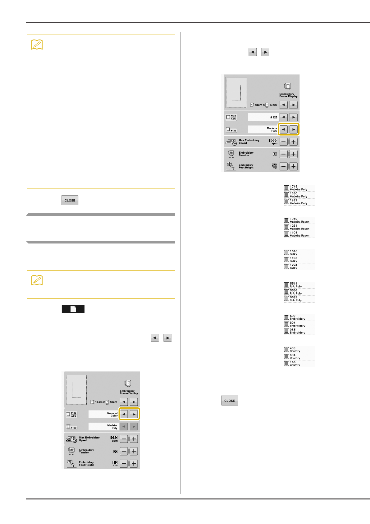
MAKING EMBROIDERY ADJUSTMENTS
Memo
Memo
#123
• “spm” is the number of stitches sewn in one
minute.
• Decrease the sewing speed when
embroidering on thin, thick, or heavy
fabrics.
• The sewing speed can be changed after an
embroidery has been started.
• The maximum sewing speed setting does
not change until a new setting is selected.
The setting specified before the main power
is set to OFF remains selected the next time
that the machine is turned on.
• Decrease the sewing speed to 600 spm
when using a speciality thread like a
metallic thread.
• While selecting the bobbin work pattern, the
embroidery speed recommendation is set at
“100 spm”; however you can choose from
100 spm, 200 spm, or 350 spm.
When the thread number is
c
displayed, use to select from six
embroidery thread brands pictured below.
MADEIRA /POLYESTER
THREAD#
Press .
c
Changing the Thread Color
Display
You can display the name of the thread colors or
embroidery thread number.
• Colors on the screen may vary slightly from
actual spool colors.
Press .
a
In the “Thread Color Display”, use
b
to display the name of the thread colors or
the embroidery thread number.
MADEIRA RAYON THREAD#
SULKY THREAD#
ROBISON-ANTON/POLYESTER
THREAD#
EMBROIDERY / POLYESTER
THREAD#
COUNTRY/COTTON THREAD#*
* Depending on the country or area, cotton-like
polyester thread is sold.
E-34
Press .
d
 Loading...