

Page 1

IP200 User Manual
Aztech Systems
VoIP Business Phone
IP200User Manual
Version 0.9
Mar 19, 2007
Page 1 of 72
Page 2

IP 200 User Manual
Copyright © 2007 Aztech Systems Limited.
All rights reserved.
No part of this document may be reproduced or transmitted in any form
without the written permission of Aztech Systems Limited.
The information contained in this document is subject to change without
notice. Although Aztech Systems attempted to ensure the accuracy of this
document, this document may include errors or omissions. The examples and
sample programs are for illustration only and may not be suited for your
purposes. You should verify the applicability of any example before placing
the product into use.
These materials are provided "As Is" without warranty of any kind, either
express or implied, relating to sale and/or use of Aztech products including
liability or warranties relating for a particular purpose, consequential or
incidental damages, merchantability, or infringement of any patent,
copyright, or other intellectual property right. Aztech Systems further does not
warrant the accuracy or completeness of the information, text, graphics, or
other items contained within these materials. Aztech Systems shall not be
liable for any special, indirect, incidental, or consequential damages,
including without limitation, lost revenues, or lost profits, which may result from
the use of these materials.
IP200 is a trademark of Aztech Systems Limited. All other company or product
names mentioned are used for identification purposes only and may be
trademarks of their respective owners.
Page 2 of 72
Page 3

IP 200 User Manual
Global Offices
Headquarters:
Aztech Systems Ltd
No. 31 Ubi Road 1, Aztech Building,
Singapore 408694
Tel: (65) 6741-7211
Fax: (65) 6749-1198
http://www.aztech.com/
Asia:
Aztech Systems (H.K.) Ltd
Rooms 2-10, Third Floor,
No. 1 Science Park East Avenue
Hong Kong Science Park, Pak Shek Kok,
Shatin, New Territories, Hong Kong
Tel: (852) 2757-1177
Fax: (852) 2753-0578
Az-Technology Sdn Bhd
No. 105-106, Ground Floor, Block A,
Kelana Business Centre,
No. 97, Jalan SS7/2, Kelana Jaya,
47301 Petaling Jaya, Selangor, Malaysia
Tel: (603) 7804 8450
Fax: (603) 7804 8457
Aztech Communication Device (SZ) Ltd
Block C, Rooms 306-308,
Intelig Technology Digital Park,
No 8, Hong Mian Road,
Futian Free Trade Zone,
Shenzhen, China
Tel: (86)(755) 2533 1110
Fax: (86)(755) 2533 1117
Aztech Communication Device (DG) Ltd
Jiu Jiang Shui Village,
Chang Ping Town, Dong Guan City,
Guang Dong Province, China
Tel: (86) (769) 83931888 or 83936688
Fax: (86) (769) 83931138
Europe:
Aztech Systems GmbH
Kreuzberger Ring 21 65205
Wiesbaden, Germany
Tel: (49)(0)(611) 9748 450
Fax: (49)(0)(611) 9748 455
North America:
Aztech Labs, Inc
4005 Clipper Court
Fremont, CA 94538, USA
Tel: (1)(510) 683 9800
Fax: (1)(510) 683 9803
Subsidiaries:
Shiro Corporation Pte Ltd
31 Ubi Road 1, # 07-00, Aztech Building
Singapore 408694
Tel: (65) 6843 1333
Fax: (65) 6749 3083
http://www.shirocorp.com/
Shiro Corporation (HK) Ltd
Rooms 2-10, 3/F, No. 1 Science Park East Ave,
Hong Kong Science Park, Pak Shek Kok,
Shatin, New Territories, Hong Kong
Tel: (852) 2757 1177
Fax: (852) 2753 0578
Page 3 of 72
Page 4

IP 200 User Manual
Contents
1
Introduction................................................................. 6
2
3
1.1 Phone Features ................................................................6
1.2 Requirements ...................................................................8
Installation................................................................... 9
2.1 Package Contents..........................................................9
2.2 Safety Notes......................................................................9
2.3 Connection.....................................................................10
2.4 Setup................................................................................11
2.5 Deployment Sample.....................................................11
Physical Details......................................................... 13
3.1 Keypad Description.......................................................13
3.2 LCD Description .............................................................15
3.3 Basic Soft button features............................................16
3.4 Hardware Specification ...............................................17
4
5
6
Page 4 of 72
Phone Configuration Guide .................................... 18
4.1 Configuring via IP200 ...................................................18
4.2 Configuring via Web Interface ...................................23
4.3 Aztech Auto-Provisioning .............................................28
Understanding the Web User Interface.................. 29
5.1 The Basic Web Interface ..............................................29
5.2 The Advanced Web Interface....................................41
Functions ................................................................... 59
Page 5

IP 200 User Manual
6.1 Menu Structure...............................................................59
6.2 Making and Answering Calls.......................................60
6.3 Handling Calls ................................................................61
6.4 Phonebook .....................................................................63
6.5 Call Logs..........................................................................64
6.6 Call Settings ....................................................................65
7
Troubleshooting ........................................................ 69
Glossary of Terms .................................................................. 71
Page 5 of 72
Page 6

IP200 User Manual
1 Introduction
Thank you for purchasing Aztech IP200 Business Phone. You made an
excellent choice and we hope you will enjoy all its capabilities.
Aztech IP200 is full-feature telephones that provide voice
communication over an IP network using the SIP IP telephony
protocol. It is suitable for office use, allowing you to place 3-way
conference call, call transfer, call waiting, caller identification and
name display, voice mail, hands free speakerphone, call hunting, call
forward, DID support and more.
1.1 Phone Features
• Support SIPP (RFC 3261)
• STN Type LCD dot matrix, 102X 68 dots
8 multi- functional soft keys
•
• 200 Entries of Phonebook
• DID Support
• Speakerphone support
• 3-way Conference Call
• 10 Last number redial
• Headset support
• Call hold
• Do not disturb
• Caller ID & Name display
• Consultation hold
Page 6 of 72
Page 7

IP 200 User Manual
• Call waiting
Call transfer - Blind
•
• Automatic call transfer
• Call transfer - Attended
Call redirecting to External Number
•
• Call forward - Unconditional
• Call forward - Busy
• Call forward - No Answer
• Group call forwarding
• Call park/retrieve
• Call Pick-up Group
• Voicemail
• Ring back
• Instant messaging
• Message Indicator
• Automated attendant
• Outgoing Call Barring
• Auto dial (Speed dial Last number)
Intercom
•
• Call Hunting
• Headset support mode
• Follow me (Local or remote extension)
• Customer details retrieval
Page 7 of 72
Page 8

IP 200 User Manual
1.2 Requirements
• A SIP based IP PBX system or network installed and running with a
SIP account created for the new IP200
• 802.3 Ethernet/Fast Ethernet LAN
Page 8 of 72
Page 9

IP 200 User Manual
One Handset
2 Installation
2.1 Package Contents
• One IP200
•
• One Handset Cable
• One Power Adapter
• Two CAT-5 UTP Straight Ethernet Network Cables (RJ-45)
• One User Manual
• One Easy Start Guide
2.2 Safety Notes
• Use the 5V power supply included in the package. Using a
different power supply may cause damage to the phone, affect
its behavior, or induce noise.
• Do not place the phone on carpets or other materials that may
block the air vents to avoid overheating.
• Place on an even surface to help the rubber pads maintain a
secure grip.
Attach the footstand and handset cord properly
•
• To clean, use an anti-static cloth. Avoid using cleaning liquids that
may damage the surface or the internal electronics of the phone.
Page 9 of 72
Page 10
IP 200 User Manual
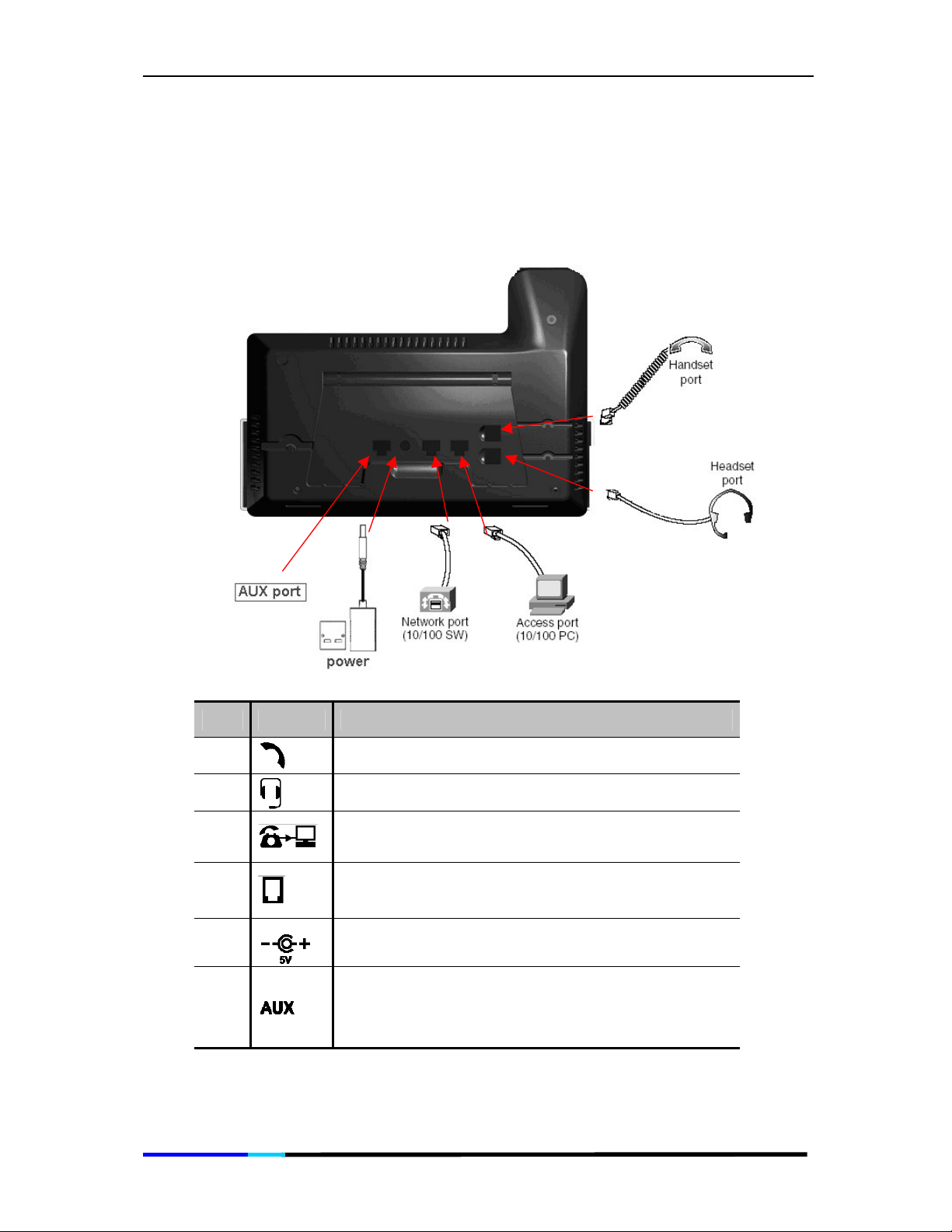
2.3 Connection
Connection diagram:
The table below describes the connectors on IP200:
Item Sign Function
1
2
3
4
5
6
Handset jack
Headset jack
10/100 Base-T Ethernet Jack (RJ-45) for
connecting to your PC/Notebook Network card
10/100 Base-T Ethernet Jack (RJ-45) for
connecting to Ethernet.
Power jack for connecting to the power adapter
in the package.
Auxiliary jack for connecting to extra devices like
fax, analog telephone connection or Power Fail
Transfer and so on.
Page 10 of 72
Page 11
IP 200 User Manual
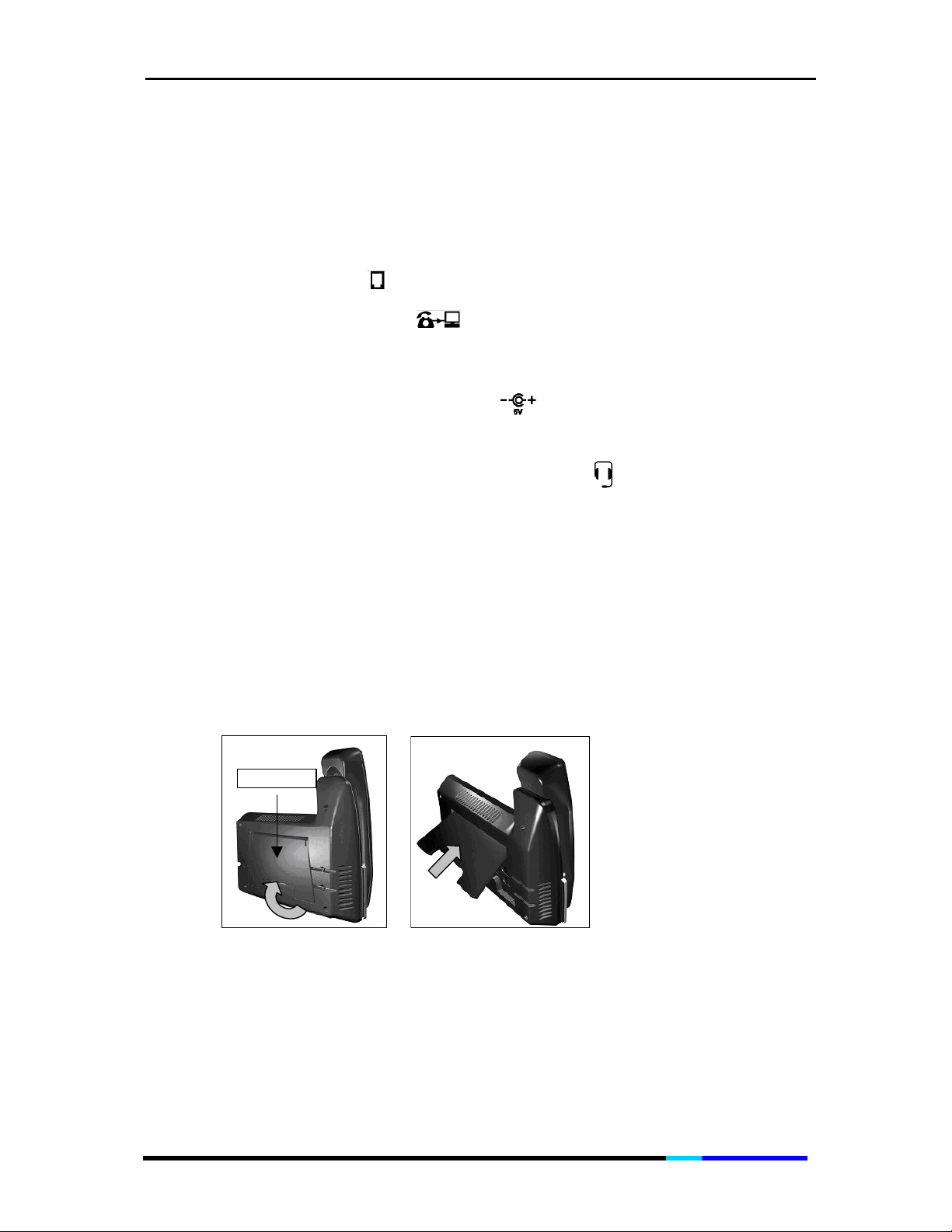
Connection procedure:
1. Rotate the footstand, please refer to the Setup section for details.
2. Connect the phone to the network, insert the Ethernet cable into
the port labeled and then insert the other end into the network;
3. Connect the LAN port of the IP200 to your PC with Ethernet
RJ-45 cable.
4. Connect IP200 to a power source, insert the power supply
connector into the port labeled and then plug it into the
power source.
5. Connect the headset into the port labeled at the bottom of
the phone (optional).
2.4 Setup
1. Turn the phone upside down;
2. Push the footstand 60° to snap the two remaining pegs into place.
Please refer to the pictures below for the correct placement of the
footstand. Please refer to the figure as shown below.
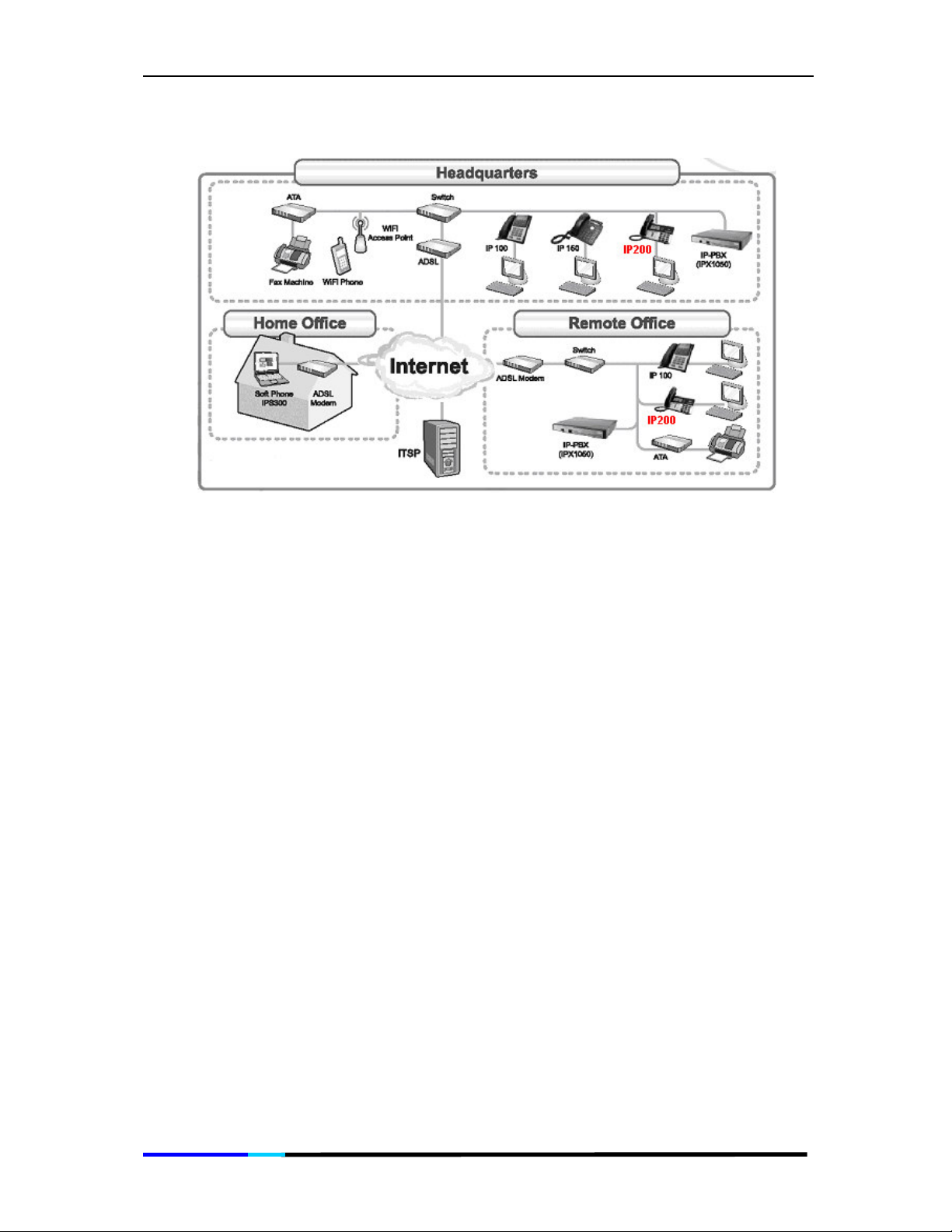
2.5 Deployment Sample
The following diagram is one deployment sample for your information.
Page 11 of 72
Page 12
IP 200 User Manual
Page 12 of 72
Page 13
IP 200 User Manual
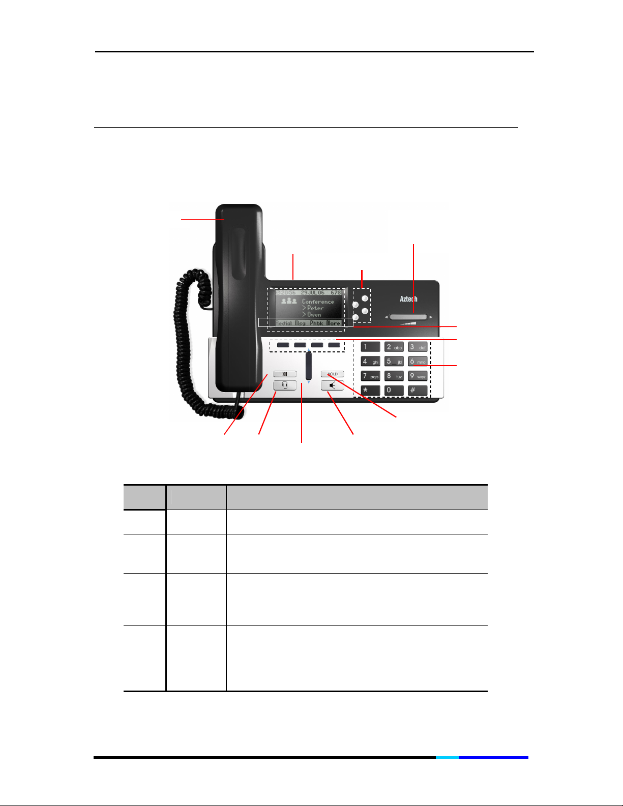
Handset
LCD
Line or short cut
Dialing pad
Soft keys
Soft key features
3 Physical Details
3.1 Keypad Description
Volume /
Left and right key
Mute
key
Headset
key
Up and
down key
Speakerphone
key
Hold key
Item Name Function
1 Handset Functions like a traditional handset.
The IP Phone “desktop” which displays the time,
2 LCD
3
4
Line or
short cut
keys
Volume
key/Left
& Right
Scroll key
date, your phone number, caller ID, line/ call
status and the soft key tabs.
Enables you to select the corresponding line
option displayed on the LCD screen and perform
the function of first soft key on the left hand side.
Increases or decreases the volume for the
current active voice receiver: handset, headset,
or speakerphone;
Enables you to scroll left or right through text and
select features that are displayed on the LCD.
Page 13 of 72
Page 14

IP 200 User Manual
5 Soft keys
6
7
8 Hold key Enables you to hold the calls.
9
10
11
12 Mute key
Soft key
features
Dialing
pad
Speakerphone
key
Up &
Down
Scroll key
Headset
key
Soft key functions change depending on the
status of the phone (for example, you are on a
call or the phone is not in use). The key’s current
function is shown on the bottom of the LCD
screen.
Shows available choices based on current
phone functions. Displayed on the last line of
LCD screen.
Press the dial pad keys to dial a phone number.
Dial pad keys work exactly like those on your
existing telephones.
Enables you to be hand-free.
Enables you to scroll up or down through text
and select features that are displayed on the
LCD screen.
Headset activation key. Enables you to use
headset for calls.
Enables you to mute / un-mute the microphone
during a call.
Page 14 of 72
Page 15
IP 200 User Manual
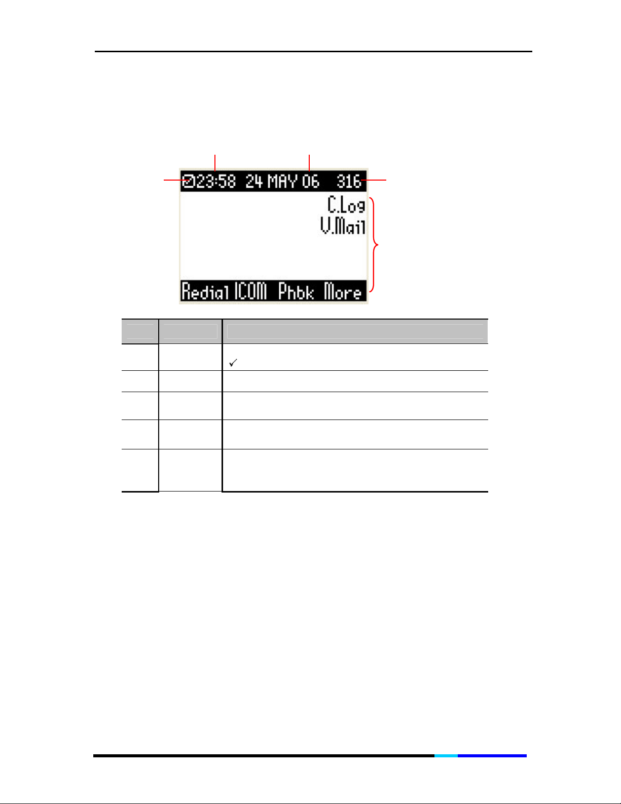
Time
Date
Time
3.2 LCD Description
Network Icon
Item Name Icon Definition
Extension No.
Functions
1
Network
Icon
2 Time
X shows network disconnected;
shows network connected.
Shows the time you have set
3 Date Show the date you have set
4
Extension
No.
Shows the extension number of IP200
Shows the functions of IP200. Press the
5 Functions
corresponding soft key to enable the function,
and press
soft key to display more functions.
More
Page 15 of 72
Page 16

IP 200 User Manual
3.3
Basic Soft button features
The soft buttons below the LCD screen allow you to easily select
phone functions. For basic soft button feature definitions, see the
table below. Other buttons are explained in the Manual
Configuration section of chapter 4.
Item Name Icon Definition
1 Redial
2 IntC Allows you to place intercom calls
3 Phbk
4
5 Follo Allows you to set Follow me.
6 Here Allows you to set use follow me.
7 P.up
DND
Displays a list of recently called numbers
Press to enter the phonebook
Do not disturb. Sends incoming calls to voice mail, or
gives a busy signal if voice mail is not available (see
item 5 in Setup for details)
Pickup a call from another phone in your group
8 C.Fwd
9 Set Allows you to enter the basic settings page.
10 VMSet Allows you to set voice mail
11 Moni
12 C.ReD
13 Trans
14 Conf
15 Park Press to park a call on hold during the active call.
16 C.hlod
17 More
Forwards calls, with 3 options: When there is no
answer, Unconditional, When the line is busy.
Allows you to set the number, whose status will be
monitored by this IP phone.
Call redirect. Redirects all the incoming calls to PSTN
lines.
Press to transfer a call to another extension during
the active call.
Press to initiate a conference call when the first call
in connected.
Press this soft key during an active call, and then you
can initiate a Consultation Hold.
Allows you to view more functions.
Page 16 of 72
Page 17

IP 200 User Manual
3.4 Hardware Specification
Model
LAN interface 2xRJ45 10/100Base-T
Power
Headset Jack
LED 4 LED with different indication purposes
Dimension
(Standing)
Weight
Temperature
Humidity
Compliance CE / FCC
IP200
Integrated IEEE 802.3af PoE support,
Optional Switching Mode Power Adapter
Input: 100-240VAC 50-60 Hz
Output: +5VDC, 2A
RJ connector (standard telecom handset
connector)
W: 250mm
H: 177mm
D: 150mm
0.77 Kg
32-113 °F
0-40 °C
30%-90%
(non-condensing)
Page 17 of 72
Page 18

IP 200 User Manual
4 Phone Configuration Guide
4.1 Configuring via IP200
When the IP200 is turned on the first time, you should configure the
following first so that you can use the phone to place VoIP calls:
a. VoIP Setting
i. SIP Configuration
ii. User Configuration
b. Network Setting
i. WAN Configuration
ii. DHCP
iii. MAC Address
iv. LAN Configuration
v. DNS Proxy
vi. Add DNS Server
c. Date / Time
d. Ring Tone
e. Ring Volume
f. Contrast
g. Mic Gain
h. Super User Password
i. Factory Setting
j. Save&Reset
k. SW Version
Page 18 of 72
Page 19
IP 200 User Manual
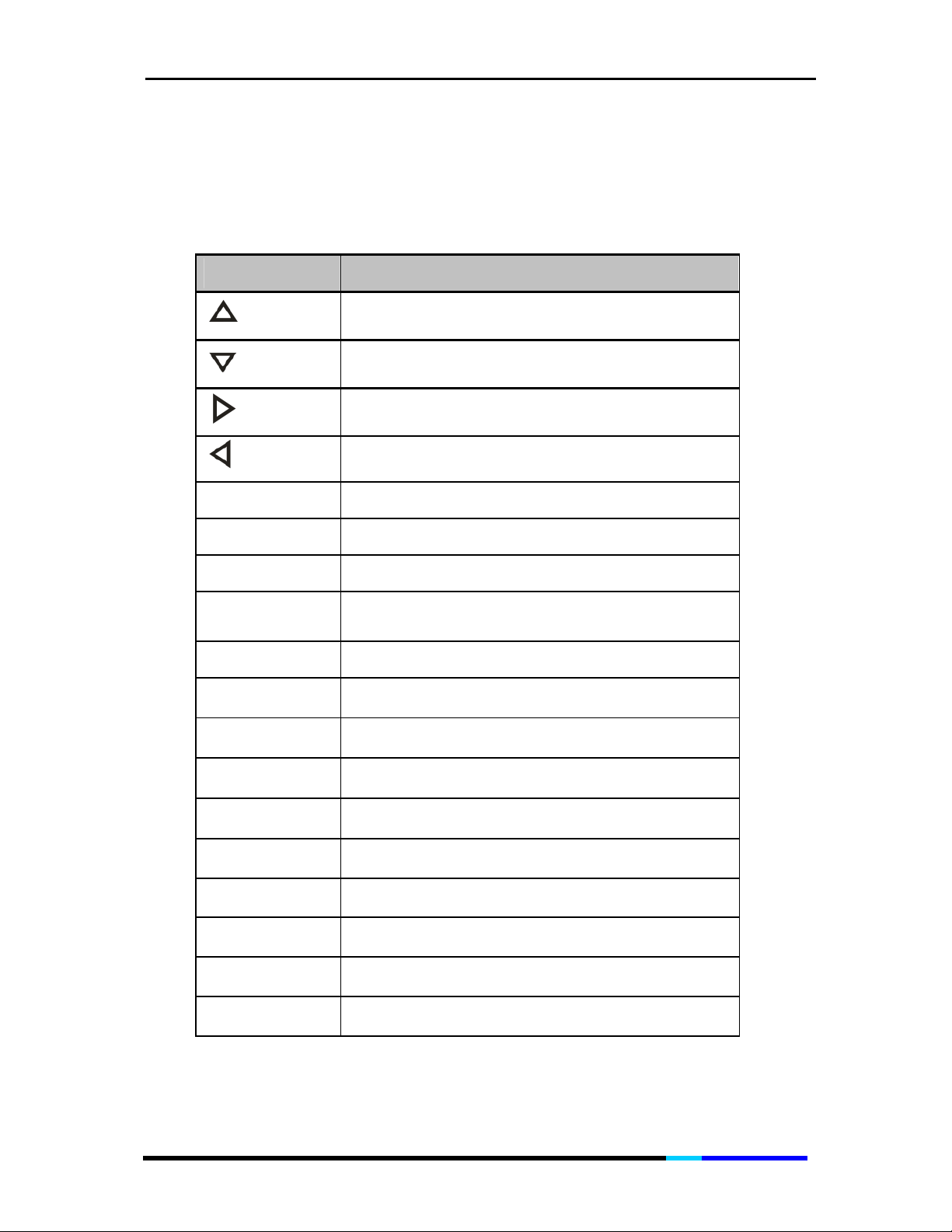
Manual Configuration
When manually configuring the VoIP and network settings, use below
keys to edit your entries.
Key Function
Soft key
Dial
Soft key
Call
Select
Cancel
Soft key
Del
Soft key
Act
Add Soft key Allows you to add an entry
Press to dial number displayed on the LCD
Press to dial the highlighted number.
Soft key
Soft key
Actives the highlighted entry
Moves cursor up
Moves cursor down
Moves cursor to the right
Moves cursor to the left
Choose the item you want to change or review
Cancels any changes you have made, if
pressed before OK or Save
Deletes an entry
Soft key
Edit
Clear
Save
Back
Next
Soft key
OK
More
Soft key
Soft key
Soft key
Soft key
Edits part of an entry
Soft key
Clears the previous character
Saves your choice
Goes back to the previous option
Moves to the next page
Confirms your choice
Allows you to view more options
Page 19 of 72
Page 20
IP 200 User Manual
* Pressed for “.”
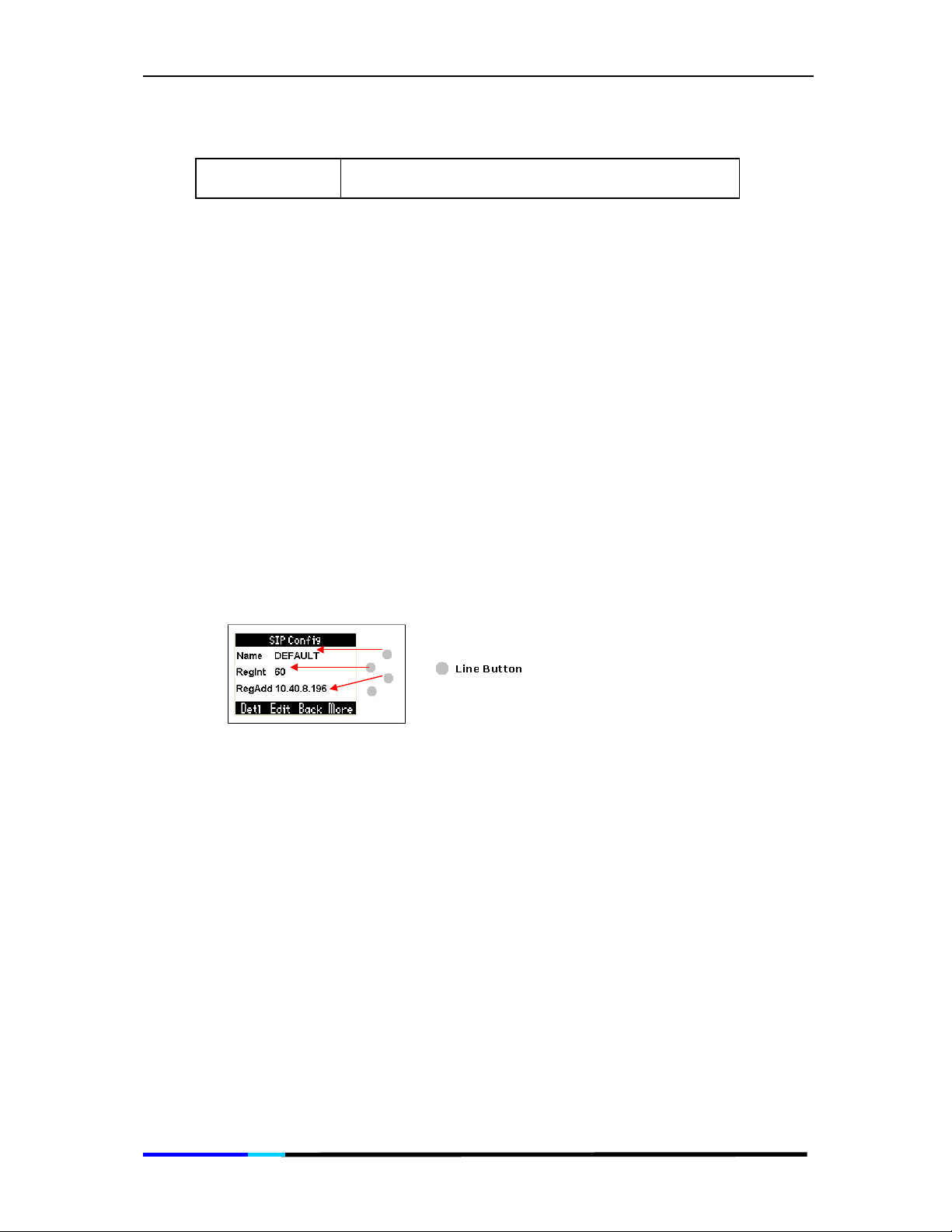
VoIP Settings
SIP Config/ User Config
IP200 supports up to 4 independent SIP accounts. Each account
owns independent SIP Server, user and NAT settings among others.
1. Use More soft key to display the Set tab;
2. Press the Set soft key, and then use the scroll key to select VoIP
Setting, press the Select soft key;
3. Press Select soft key to enter SIP config or press up&down scroll key
to locate User Config and press Select soft key;
• To check the details —Press Det soft key;
• To edit —Press Edit soft key and press the line key for the line
you desired to edit.
• To add —Press More soft key to display Add tab and press to
Add soft key to edit.
• To delete —Press More soft key to display Del tab and press the
Del soft key.
• To enable— Press More soft key to display Ena tab and press
the Ena soft key
Network Settings
WAN Configuration
1. Use More soft key to display the Set tab;
2. Press the Set soft key, and then use the scroll key to select Network
Setting, press the Select soft key;
Page 20 of 72
Page 21

IP 200 User Manual
3. Use the scroll key to view the menu list (DHCP, MAC Address, LAN
Config, DNS Proxy, Add DNS Server);
4. Go to the location WAN Config;
5. Press the line key for the line you desired to edit, and then edit the
configuration (refer to Manual Configuration form for more key
functions).
You are allowed to enable or disable DHCP under the NET mode, also
configure LAN settings, set DNS Proxy and add new DNS Proxy if
needed.
Date / Time Setting
1. Use More soft key to display the Set tab;
2. Press the Set soft key, and then use the scroll key and Select soft
key to enter
Date / Time;
3. Use the up&down scroll key and Select soft key again to enter
Date Set / Time Set;
4. Edit the Date and time and press OK soft key (for example:
change the Date: 29/05/2006 to 30/05/2006):
• Press left&right scroll to move the cursor to digit “9” [2I9/05/2006]
and press 0 [20/05/2006], and then move the cursor back to
digit “2”[I20/05/2006] and press 3[30/05/2006]. This design is to
make user entries logical date and time.
Ring Tone / Volume
1. Under Set mode, for
Ring Tone
, press the
Select
soft key to enter
directly. For Ring Volume, use up&down scroll key to locate, and
then press the Select soft key.
2. Press up&down scroll key to select the desired tone / volume and
press Select soft key to confirm.
Contrast Setting
1. Under Set mode, use the scroll key and Select soft key to enter
Contrast;
Page 21 of 72
Page 22

IP 200 User Manual
2. Press the scroll key to select the contrast level and press the Select
soft key.
Mic Gain
You are allowed to set the volume the recipient receives (1-6 levels):
1. Under Set mode, use the scroll key and Select soft key to enter Mic
Gain, and use the scroll key to select Handset Mic / Headset Mic/
Speaker Mic;
2. Use scroll key and Select soft key to choose the one you desired to
set.
Inputting Super User Password
There is no password for the first time. You can set the new password
here, or keep it blank.
1. Under Set mode, use the scroll key and
Select
soft key to enter
Super User Pwd, key in the password;
2. Press Ok soft key to confirm, key in the new password;
3. Press Ok soft key, key in the new password once again to confirm;
Press Ok soft key to confirm, then the password is changed.
4.
Factory Setting
1. Under Set mode, use the scroll key and Select soft key to enter
Factory Setting;
2. Press the scroll key then Select soft key to select Yes / No. When
Yes is selected, key in the super user password, and press OK soft
key to resume factory default setting. If your password remains the
default setting, the system will resume factory default setting
without asking password.
Page 22 of 72
Page 23

IP 200 User Manual
Save & Reset
This is to confirm all the setting above for the phone:
1. Under Set mode, use the scroll key and Select soft key to enter
Save & Reset;
2. Press the scroll key then Select soft key to select Yes / No; When
Yes is selected, key in the super user password, and press OK soft
key to resume factory default setting. If your password remains the
default setting, the system will resume factory default setting
without asking password.
Software Version
•
Under Set mode, use the scroll key and Select soft key to enter SW
Version to view the software version.
4.2 Configuring via Web Interface
Registration Procedure
For non-DHCP clients, please refer to Configuring your Computer.
The web interface allows you to register the IP200 with Setup pages.
And if you want to activate more functions, you are recommended
to configure Basic and Advanced phone settings, refer to
Understanding Web User Interface.
Step1. To access the web interface
1. Open your browser.
2. If your PC is connected to LAN interface, enter http://10.0.0.99/
in the address bar and press ENTER to access the IP Phone
Administration web interface using the account: username:
admin and password: epicrouter
Page 23 of 72
Page 24

IP 200 User Manual
Figure 1 Overall Status Page
Step2. Click Step 1:Network Selection link to enter the next page:
Figure 2 Network Selection page
Page 24 of 72
Page 25
IP 200 User Manual
If you have a DHCP server-enabled device (eg. router), select DHCP
Client or PPPoE, otherwise select static IP.
DHCP Client
Allows the IP200 to obtain IP address, subnet mask, gateway and DNS server
automatically from the DHCP server, if there is a DHCP server (such as a router) in
your network.
PPPoE Connection
Those ADSL and Cable Modem users please select this item for it is a protocol
especially designed for them. With this system, ADSL ISP automatically assigns all the
required IP parameters to any device connected to it when the device log on.
Username: please input the user name of the account given by your ADSL ISP.
Password: please input the password of the account given by your ADSL ISP.
Static IP
IP Address: Enter the IP address of IP200
Netmask:
Gateway: Enter the address of the router or the address of upper-gateway.
DNS Server: Key in the address of the local DNS Server.
Enter the subnet mask of the network
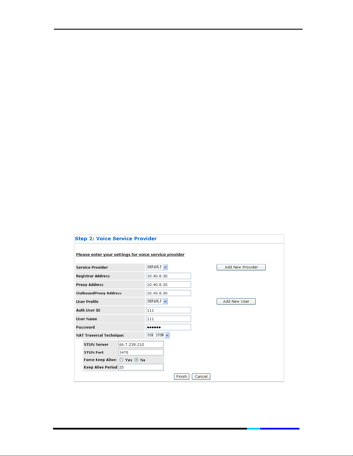
Step3. Click Proceed to Step 2 to enter the next step:
Figure 3 Voice Service Provider page
Page 25 of 72
Page 26
IP 200 User Manual
Service Provider: Press “Add New Provider” to add new SIP server, the maximum of
which is up to 4.
Registrar Address:
provider (ITSP) or IP-PBX registrar address.
Proxy Address: IP address or Domain name of proxy.
OutboundProxy Address: IP address or Domain name of Outbound Proxy, or Media
Gateway, or Session Border Controller.
User Profile: Press “Add New User” to add new user, the maximum of which is up to
4.
Auth User ID: SIP service subscriber’s Authenticate ID used for authentication.
Usually has the form of digit similar to phone number or actually a phone number.
User Name: SIP service subscriber’s Authenticate user name used for caller ID
display.
Password: SIP service subscriber’s account password for IP200 to register to (SIP)
servers of ITSP.
Quick setting: Auth User ID, User Name and Password can be input the digit ‘0’
directly so that the IP200 will auto-register to IP-PBX or ITSP.
NAT Traversal Technique:
NONE
: If the IP phone directly connected to the Modem, please select this.
USE STUN
---- Server: Enter the IP address or Domain Name of the STUN Server. The
default is 66.7.238.210. This field is applicable only if USE STUN is selected as the
NAT traversal technique.
----STUN Port: Enter the port number on which the STUN server listens for
requests from the STUN Client on ATA. The range is 1 to 65535. The default is
3478. This field is applicable only if USE STUN is selected as the NAT traversal
technique.
----Force Keep Alive: Only valid when STUN is not used. If STUN is not enabled,
and keep alive is still expected to be sent then select Yes otherwise select No.
----Keep Alive Period: The keep alive interval in seconds to be used when STUN
is not enabled.
SIP Server’s IP address or Domain name provided by VoIP service
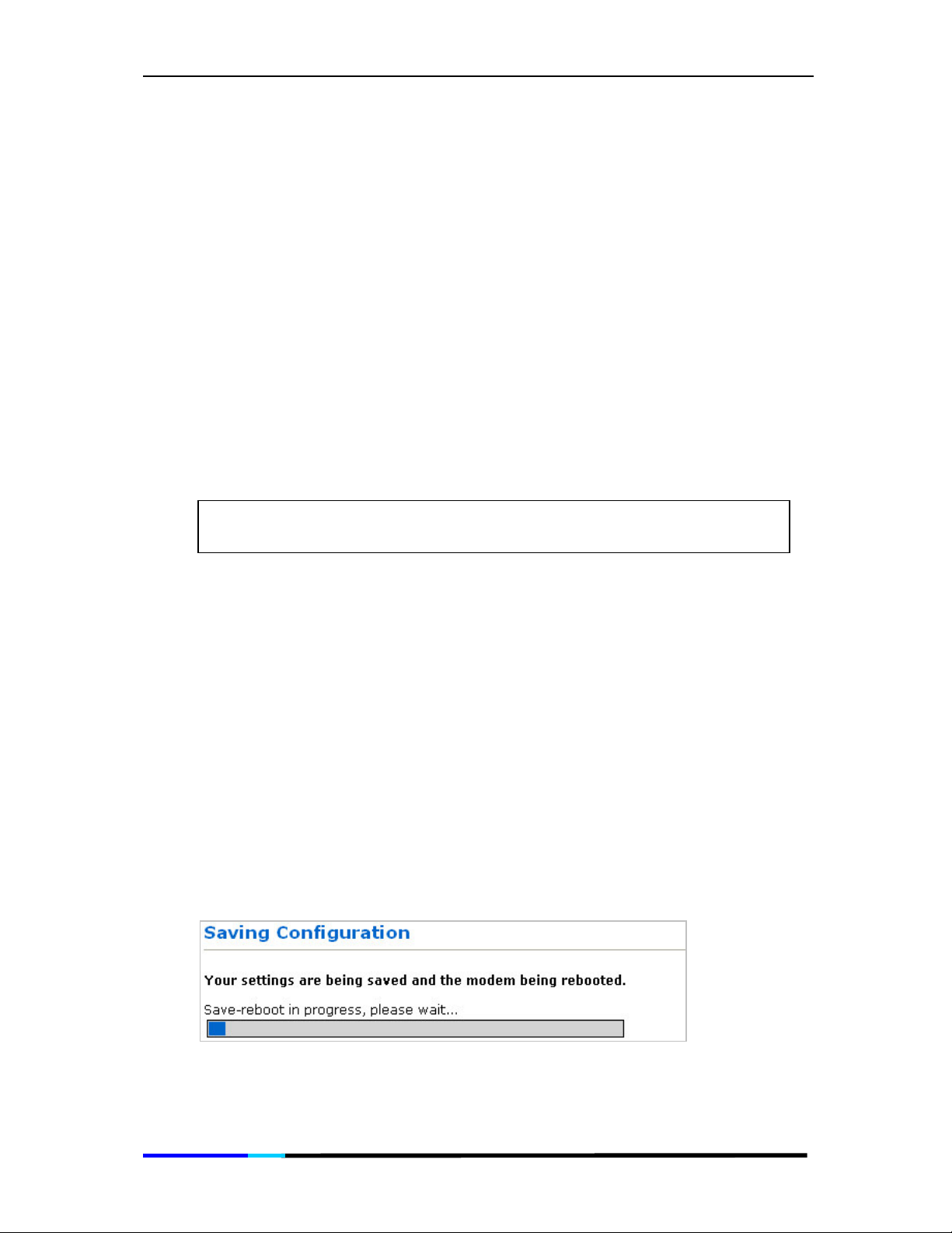
Step4. Click Finish to save the configuration. Please wait about 30
seconds for the process to complete.
Figure 4 Saving Configuration page
Page 26 of 72
Page 27

IP 200 User Manual
Configuring your Computer
If you do not have a DHCP network, you need to manually configure
your computer to access the user interface. These instructions are
only applicable for phones that are not part of a DHCP network.
1. Connect one end of RJ45 to LAN port ( ), and the other end
to PC.
2. From your desktop, select Start > Run. Enter control ncpa.cpl and
then click OK. This opens Network Connections.
3. Right-click LAN and then select Properties.
4. In the Local Area Connection Properties dialog box, select Internet
Protocol (TCP/IP) and then click Properties.
5. In the Internet Protocol (TCP/IP) Properties dialog box, select Use
the following IP address. Enter the IP address:10.0.0.100 and
Subnet mask:255.255.255.0.
6. Click OK to close the
Internet Protocol (TCP/IP) Properties
dialog
box.
7. Click Close to close the Local Area Connection Properties dialog
box.
Page 27 of 72
Page 28

IP 200 User Manual
4.3 Aztech Auto-Provisioning
IP200 can be registered to the server and gets its extension number
automatically when connected to Aztech IPX1050, there is no need
to set parameters except the registrar address of Aztech IPX1050, and
then you can use IP200 to place calls. Here is a diagram example for
you to set up the connection:
Page 28 of 72
Page 29
IP 200 User Manual
Top Pane
Left Pane
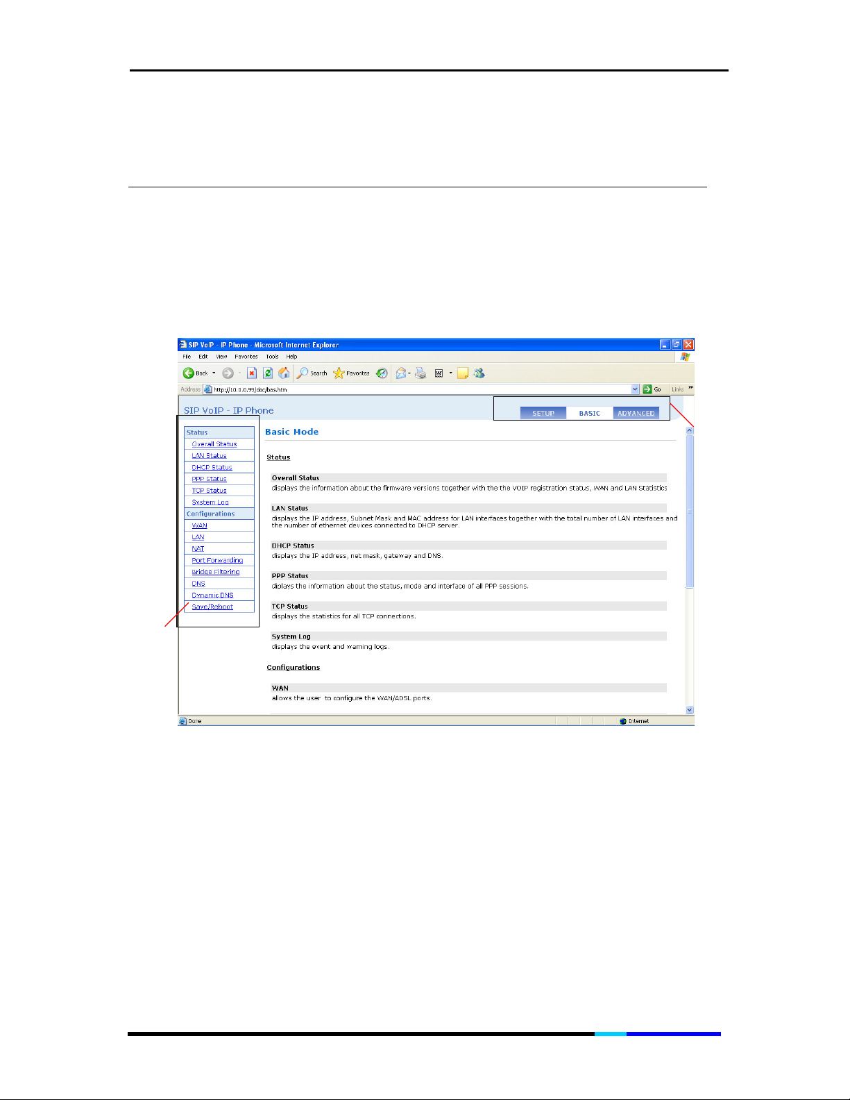
5 Understanding the Web User Interface
The IP Phone Web Interface is divided into three sections – top, left,
and main panes. Navigation is done using the top and left panes.
These panes display the menus and links that you can select to go to
a certain configuration page.
Figure 5 Basic Main page
5.1 The Basic Web Interface
The Basic Web Interface contains two parts, the Status and
Configurations. Click one link on left pane to view the certain page.
Page 29 of 72
Page 30
IP 200 User Manual
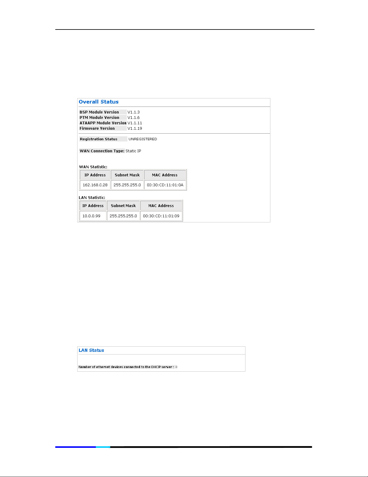
Overall Status
Shows you the software module versions, the registration status and
the network connections status.
Figure 6 Overall Status page
Version: Shows the BSP Module Version, PTM Module Version, ATAAPP Module
Version and Firmware Version.
Registration Status: Shows whether the IP Phone is registered to the server or not.
WAN Connection Type: Shows you the connection type, which can be static IP or
DHCP Client.
WAN Statistic:
LAN Statistic: Displays the LAN settings of the IP phone.
Displays the WAN settings of the IP phone.
LAN Status
Shows you the number of Ethernet devices connected to the DHCP
server.
Figure 7 LAN Status page
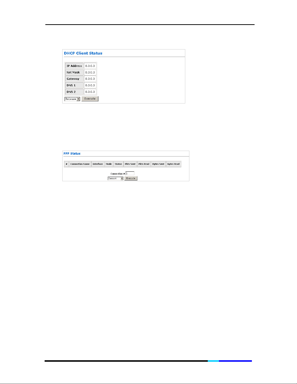
DHCP Status
This table shows the information and status of the WAN.
Page 30 of 72
Page 31
IP 200 User Manual
Figure 8 DHCP Client Status page
PPP Status
The PPP Status page shows the status of each PPP(Point-to-Point
Protocol) session for each PPP interface.
Figure 9 PPP Status page
Connection Name: This is user defined. User defined connections for PPP can be
created in PPP Configuration page.
Interface: States the interface that is being used (Ethernet 1 or VPNO).
Mode: There are two available modes for the connection:
• PPP over Ethernet (PPPoE)
• PPP over VPN (PPPoV)
Status: Shows whether PPP connection is connected or not.
Packets Sent: Number of packets sent by a particular PPP Connection.
Packets Received: Number of packets received by a particular PPP Connection.
Bytes Sent:
Bytes Received: Number bytes received by a particular PPP Connection.
Connect and Disconnect: This field allows you to manually connect/disconnect the
PPPconnection for each PPP interface. In other words, each PPP session can be
connected and disconnected individually.
• Connection #: Specifies the PPP session to be connected/disconnected.
• Connect/Disconnect Execute: Press this button to either connect or
disconnect.
Connection status dialog will be displayed below the Execute button after it is
pressed. Sample dialog with explanation:
Number of bytes sent by a particular PPP Connection.
Page 31 of 72
Page 32

IP 200 User Manual
• PPP X: Connecting... This is displayed while the PPP session is attempting to
connect to the ISP.
PPP X: Connect ERROR
•
due to an error.
• PPP X: is currently not connected This is displayed when a disconnect attempt
is made on a session that is not currently connected.
• PPP X: does not exist! This is displayed when a connect or disconnect attempt is
made on a session number that does not exist.
TCP Status
Shows you the TCP (Transfer Control Protocol) status. You are allowed
to reset the counters by clicking
This is displayed when a connection cannot be made
Reset Counters.
Figure 10 TCP Status page
General: Total Packets, Data Packets, Data Bytes, Out of Order Packets, Out of
Order Bytes
Discarded Packets: Bad Checksum, Bad Offset Header, Too Short
Connections: Initiated, Accepted, Established, Closed.
Reset Counters: This button allows user to reset the TCP Status counter.
System Log
Shows the events triggered by the system. This page contains
information that is dynamic and will refresh every 5 seconds.
Figure 11 System Log page
Page 32 of 72
Page 33

IP 200 User Manual
Log Message: Allows you to choose the type of the log message shows below.
• ALL
Event
•
Clear Log: This field allows you to clear the current contents of the System Log.
Save Log: This field allows you to save the current contents of the System Log by
right click HERE and select “Save Target As” to save it into a text file.
WAN Configurations
Allows you to do WAN side configurations, which contain Bridge,
IGMP, Static IP Settings, DHCP Client, MAC Spoofing and PPP.
Figure 12 WAN Configurations page
Bridge: Enable to connect the LAN to the WAN (bridge the two connections). This is
available in Bridge Mode only. Default is Disabled.
IGMP: IGMP (Internet Group Management Protocol) relay/proxy specification
andenvironment, default is Disabled. IGMP is available in all modes and all
encapsulations.
Static IP Settings: Static IP Settings are for users who have a Static IP Address (WAN
side) from their ISP.
• IP Address: Range for IP Address is x.x.x.y, where 0 x 255, 1 y 254.
• Subnet Mask: Range for Subnet Mask is x.x.x.x, where 0 x 255.
• Gateway: Range for Gateway is x.x.x.y, where 0 x 255 and 1 y 254.
Input the address of the router or the gateway.
Page 33 of 72
Page 34

IP 200 User Manual
DHCP Client: You may enable DHCP server for WAN port here. It is disabled default.
• Host Name: When DHCP Client is enabled, copy the ISP recognized Host Name
here, which is up to 19 characters.
MAC Spoofing: Enable MAC Spoofing to make a different MAC Address appear on
the WAN side. This is also used to solve the scenario where the ISP only recognizes
one MAC Address. Default is Disabled.
• MAC Address: When MAC Spoofing is enabled, copy the ISP-recognized MAC
address here. Format for MAC address is six pairs of hexadecimal numbers (0-9,
A-F) separated by colons. Default is 00:00:00:00:00:00.
PPP
Enable:
•
interface. This box is unchecked by default.
• User Name: Enter the PPP user name (provided by the ISP). The User Name can
be up to 127 characters.
Note: You cannot have two different user accounts with the same account name.
If a different User Name with an already existing Account ID is submitted, it will
replace the previous account with that Account ID. You can have the same User
Name and Password for two different accounts (Account ID).
When checked, the router will use PPP to connect to the WAN
Password:
•
needed to delete or modify the account. The Password can be up to 127
characters.
• Service Name: The Service Name of the PPP session is required by some ISPs. If
the ISP does not provide the Service Name, please leave it blank.
• MRU: The MRU (Maximum Receive Unit) field indicates the maximum size IP
packet that the peer of PPP connection (this device) can receive. During the
PPP negotiation, the peer of the PPP connection will indicate its MRU and will
accept any value up to that size. The actual MTU of the PPP connection will be
set to the smaller of the two (MTU and the peer’s MRU). In the normal
negotiation, the peer will accept this MRU and will not send packet with
information field larger than this value. Range for MRU field is 0-32767, default
value is 1492.
• MTU: Maximum Transmission Unit (MTU) is the largest size packet that can be
sent by the modem. If the network stack of any packet is larger than the MTU
value, then the packet will be fragmented before the transmission. During the
PPP negotiation, the peer of the PPP connection will indicate its MRU and will
accept any value up to that size. The actual MTU of the PPP connection will be
set to the smaller of the two (MTU and the peer’s MRU). Range for MTU field is 0-
32767, default value is 1492.
• MSS: Maximum Segment Size is the largest size of data that TCP will send in a
single, un-fragmented IP packet. The LAN client and the WAN host will indicate
their MSS during the TCP connection handshake. Range for MSS field is 0-32767,
default value is 1432.
Authentication: The different types of available authentications are:
•
-Auto: When auto is selected, PAP mode will run by default. However, if PAP
fails, then CHAP will run as the secondary protocol. This is the default setting.
-PAP: Password Authentication Procedure. Authentication is done through
username and password.
Enter the PPP password (provided by the ISP). The Password is not
Page 34 of 72
Page 35
IP 200 User Manual
-CHAP: Challenge-Handshake Authentication Protocol. Typically more secure
than PAP, CHAP uses username and password in combination with a randomly
generated challenge string which has to be authenticated using a one-way
hashing function.
• Automatic Reconnect: When it is checked, the HNP Router will reconnect a PPP
session when it is terminated by the ISP. If a PPP session is terminated under any
other conditions (i.e. by Disconnect Timeout or manual disconnect), the
Automatic Reconnect will not reconnect the session. This box is unchecked by
default.
Submit: Applies the settings you did.
Reset:
Restores all settings in this page.
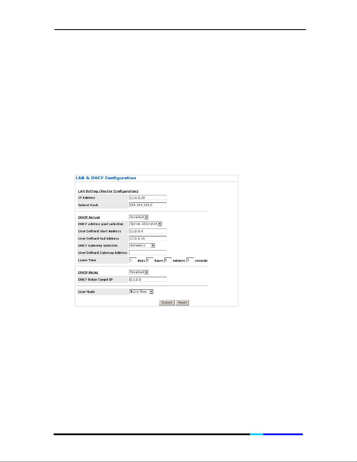
LAN & DHCP Configurations
This page allows you to set the configuration for the LAN port.
Figure 13 LAN & DHCP Configuration page
LAN IP Address & Subnet Mask: The LAN IP Address is what the computer uses to
identify and communicate with the HNP Router (this is the address you enter in the
address bar of Internet Explorer to access these pages). You can change this to
another private IP address and subnet mask, such as 192.168.1.2 and 255.255.255.0.
Range for IP Address and Subnet Mask is x.x.x.x, where 0 x 255.
DHCP Server: Dynamic Host Configuration Protocol (DHCP) is a communications
protocol that allows network administrators to manage and assign IP addresses to
computers within the network. DHCP provides a unique address to a computer in
the network which enables it to connect to the Internet through Internet Protocol
(IP). DHCP is controlled by the DHCP Server. The following settings allow you to
configure the DHCP server.
Page 35 of 72
Page 36

IP 200 User Manual
• DHCP Server: Select Enabled to activate DHCP Server.
• DHCP Address Pool Selection: Two types of Address Pool selections are
available, with System Allocated as the default.
-System Allocated: The DHCP address pool is based on LAN port IP address plus
12 IP addresses. For example, when the LAN IP address is 10.0.0.2; the DHCP
address pool the range from 10.0.0.3 to 10.0.0.14.
-User Defined: When User Defined is selected, the DHCP address pool starts at
the User Defined Start Address and ends at the User Defined End Address. The
maximum pool size can be 253 IP addresses: 255 total IP addresses – 1
broadcast address – 1 LAN port IP address.
User Defined Start Address:
•
User Defined DHCP Address Pool Selection. Range for User Defined Start
Address is x.x.x.x, where 0 x 255, default value is 10.0.0.4.
• User Defined End Address: This is the last IP address in the DHCP pool. User
Defined DHCP Address Pool Selection. Range for User Defined End Address is
x.x.x.x, where 0 x 255, default value is 10.0.0.15.
• DHCP Gateway Selection: The default setting for the DHCP Gateway Selection
is Automatic. You can select User Defined and specify User Defined Gateway
Address
LAN DHCP clients.
• User Defined Gateway Address: The purpose for the User Defined Gateway
Address is to have two gateway addresses, as the LAN IP Address at the top of
the LAN Configuration page is also a gateway address.
• Lease time: The Lease time is the amount of time a network user will be allowed
to connect with DHCP server. If all fields are 0, the allocated IP addresses will
be effective forever. Ranges for Lease Time fields: Days 0-36500, Hours 0-23,
Minutes 0-59, Seconds 0-59, default value is 1 days 0 hours 0 minutes 0 seconds.
• DHCP Relay: If it is enabled, the DHCP requests from local PCs will forward to
the DHCP server runs on WAN side. To have this function working properly,
please disable the NAT to run on router mode only, disable the DHCP server on
the LAN port, and make sure the routing table has the correct routing entry.
• DHCP Relay Target IP: If DHCP Relay is enabled, DHCP requests are relayed to
DHCP Target IP on the WAN side.
User mode:
•
. The DHCP server will issue the
This is the starting IP address of the DHCP pool for
User Defined Gateway Address
Not applicable for router application.
to the
Submit: Applies the settings you did.
Reset: Restores all settings in this page.
NAT Configuration
The Network Address Translation is configured in the NAT Settings
page. The NAT module provides Dynamic Network Address and Port
Translation (Dynamic NAPT) capability between LAN and multiple
WAN connections, and the LAN traffic is routed to appropriate WAN
connections based on the destination IP addresses and the Route
Table. This eliminates the need for the static NAT session configuration
between multiple LAN clients and multiple WAN connections. When
Page 36 of 72
Page 37

IP 200 User Manual
Dynamic NAPT is selected (default), there is no need to configure the
NAT Session and NAT Session Name Configuration.
Figure 14 NAT Configuration page
NAT: Use this field to Enable/Disable NAT. Default is Enable.
Mode: Options for the NAT dropdown menu are:
• NAT: Static peer-to-peer mode (1x1).
• NAPT: Static multiple mapping mode (1xN).
• Dynamic NAPT: Dynamic multiple mapping mode (NxN). This is the default
setting.
Submit: Applies the settings you did.
Port Forwarding Configuration
Allows you to set up port forwarding configuration.
Figure 15 Port Forwarding Configuration page
ID: This is the ID number corresponding to the Virtual Server configuration.
Start Port: This field allows you to enter the port number of the Public Network (WAN
or external network). If you are entering a range of ports, this is the first port.
Page 37 of 72
Page 38

IP 200 User Manual
End Port: This field represents the last port number in a port range. If you only want
one port number (no port range), simply enter the same number here as in the
Public Port – Start
Private Port: This field allows you to enter the port number of the Private Network
(LAN or internal network). In most cases, the private port number is same as public
port number. This port number cannot be seen from the WAN side.
Port Type: TCP/UDP
Host IP Address: This field allows you to enter the private network IP address for the
particular server.
Add: Adds the configuration you did.
field. The maximum number of the mapped Port is 20.
Bridge Filtering
Bridge Filtering allows packets to be forwarded or blocked,
depending on the MACaddress. The Bridge Filtering configuration
page allows you to set the configuration of MAC filtering.
Figure 16 Bridge Filtering page
Filtering Enable: Yes/No
Filtering Action
Block:
•
destination Destination MAC will be blocked.
• Forward: When forward is selected, everything from the Source MAC will be
forwarded to the Destination MAC.
Source MAC: This is the Source MAC to block or from which to forward. See the next
page for instructions on how to configure this. The Source MAC must consist of 12
hexadecimal characters.
Destination MAC: This is the Destination MAC to block or to forward to. See the next
page for instructions on how to configure this. The Destination MAC must consist of
12 hexadecimal characters.
Type: Enter the hexadecimal number for the Ethernet type field in Ethernet_II
packets. For example, 0800 is for IP protocol. The Type must consist of 4
hexadecimal characters.
When block is selected, everything from the
Source MAC
with
Page 38 of 72
Page 39

IP 200 User Manual
Modify: Click to modify the Bridge filtering you set.
Delete: Click to delete the Bridge filtering you set.
Add
: Click to add a new Bridge filtering.
DNS Configuration
The DNS Configuration page allows you to set the configuration of
the DNS proxy. For the DHCP requests from local PCs, the DHCP server
will set the LAN port IP as the default DNS server. Thus, all DNS query
messages will come into LAN port first. The DNS proxy on the HNP
Router records the available DNS servers and forwards DNS query
messages to one of DNS servers.
Figure 17 DNS Configuration page
DNS Proxy Enable/Disable:
process the DNS query message. For the DHCP requests from local PCs, the DHCP
server will set the user-configured DNS server as the DNS server. Then all DNS query
messages will be directly sent to the DNS servers.
Auto Discovery: When enabled (default), the DNS proxy will store the DNS server IP
addresses obtained from DHCP client or PPP into the table. All DNS query messages
will be sent to the dynamically obtained DNS server. Select this option when the
DNS Server address is unknown but provided (automatically) by the ISP.
User Configured: When enabled, the DNS proxy will use the user-configured DNS
server. All DNS query messages will be sent to the DNS server. Enter the DNS IP in the
DNS Server field. Select this option when the DNS Server address assigned by the ISP
is known. User Configured is disabled by default.
Auto Discovery + User Configured: Selecting both options will cause the DNS proxy’s
table to have all the IP addresses of dynamically obtained and user configured
DNS servers.
DNS Server:
This is the user defined DNS server URL name and IP. Default is Disabled.
When the DNS Proxy is Disabled, the LAN port does not
Page 39 of 72
Page 40

IP 200 User Manual
• URL Name (Add/Delete): This is the URL name for the DNS server. This can be up
to 255 characters.
Host IP (Add Only):
•
Apply: Applies the settings you did.
Reset: Restores all settings in this page.
DNS Proxy Setting: This is a table of all DNS server IP addresses.
DNS Server Setting: This is a table of all DNS sever URL names.
Save Configuration: Clicking this will link the user to the Save Settings / Reboot
page.
Dynamic DNS Configuration
Dynamic DNS (DDNS) is a service that facilitates outside Internet
access to a LAN host even when the host's dynamically assigned IP
address changes frequently, this makes it possible for other sites on
the Internet to establish connections to the IP phone without needing
to track the IP address.
This is the IP address of the DNS Server.
Figure 18 Dynamic DNS Configuration page
Dynamic DNS Enabled:
DNS Server: members.dyndns.org, default.
Page 40 of 72
Click the pane to enable the Dynamic DNS
Page 41

IP 200 User Manual
Update Type: This corresponds with the type of account that is registered with the
DDNS service provider.
Dyndns
•
Custom
•
• Static
Username: Fields to enter the username that was registered with the DDNS provider.
Password: Fields to enter the username that was registered with the DDNS provider.
Host Names: The host name(s) you registered with the DDNS provider is up to 5 host
names.
Apply: Saves the setting and modification you did.
Save / Reboot
Allows you to save settings and reboot the IP phone or reboot the IP
phone only without saving settings. Strongly recommend users to do
the reboot after the full configuration has been done.
Figure 19 Save Settings / Reboot page
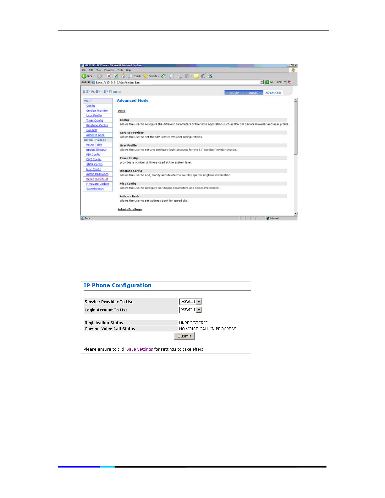
5.2 The Advanced Web Interface
The Advanced Web Interface contains two parts, the VoIP and
Admin Privilege. Click one link on left pane to view the certain page.
Page 41 of 72
Page 42
IP 200 User Manual
Figure 20 Advanced Main page
IP Phone Configuration
Allows you to select one service provider and one login account, also
shows you the registration status and the current voice call status.
Figure 21 IP Phone Configuration page
Service Provider To Use:
selected line.
Note: When a different service provider is chosen from the drop-down list, the Login
Account To Use drop-down list is updated to reflect the login details available and
configured for the selected service provider.
Select the service provider to work with the ATA for the
Login Account To Use: Select the Login Account to work with the ATA for the
selected line and the selected service provider.
Page 42 of 72
Page 43

IP 200 User Manual
Registration Status: This status shows you if the IP Phone is registered to the server or
not.
Current Voice Call Status:
Submit: Applies all the settings you did in this page.
Save Settings: Click this link to go to the Save Settings / Reboot page. On the Save
Settings / Reboot page, click Save & Reboot to permanently save the settings to
system flash memory and to reinitialize the system to the new settings.
This status shows you the current voice call status.
Service Provider Configuration
This page sets the configuration related to the SIP service provider.
Figure 22 Service Provider Configuration page
Service Provider List:
a service provider is selected from this drop-down list, the respective parameters
are automatically displayed. A DEFAULT service provider is provided with a default
set of parameters. This can be edited. New service providers can be manually
defined and added. An existing service provider can be edited or deleted.
New Service Provider: Enter the name of the service provider to be added if the
Service Provider List field is blank, or a new string to rename the service provider
displayed in the Service Provider List field.
Registration Interval (in secs):
is 0 to 2147483347 seconds. The default is 60 seconds.
Authentication Method: Select the authentication method. Only MD5 is supported.
• AUTH_NONE: Disable any authentication method.
• AUTH_MD5: Use MD5 authentication method.
Registrar Address: Enter the IP address or Domain Name of the registrar with which
the ATA must register in order to receive or send calls.
Enter the name of the service provider to be configured. When
Enter the re-registration interval in seconds. The range
Page 43 of 72
Page 44

IP 200 User Manual
Registrar Port: Enter the port number of the registrar on which it will listen for Register
requests from the ATA. The range is 1 to 65535. The default port is 5060.
Proxy Address:
Proxy Port: Enter the port number on which the SIP proxy server will listen for
messages. The range is 1 to 65535. The default port is 5060.
OutboundProxy Address: Enter the IP address or Domain Name of the Outbound
proxy server. This is useful in cases where the ATA is behind a NAT.
OutboundProxy Port: Enter the port number on which the Outbound proxy server
listens for messages from the ATA. The range is 1 to 65535. The default port is 5060.
MWI Server Address: Enter the IP address or Domain Name of Message Waiting
Server.
MWI Server Port: Enter the port number on which the Message Waiting Server listens
for messages. The range is 1 to 65535. The default port is 5060.
MWI Subscription Refresh Interval: Enter the subscription refresh interval in seconds.
The range is 0 to 2147483347 seconds.
Dial Plan String: This parameter provides the dial plan string as required by the
service provider. Modifying this field while adding a new service provider will not
take effect after ADD has been selected and Submit Changes has been clicked.
While adding a new service provider, the dial plan string takes the value from the
default dial plan string specified in the VoIP General Parameters web page only. To
modify this field, complete adding the service provider, and then edit it, select EDIT
in the drop-down box of Service Provider Action and click Submit Changes.
Note: Dial Plan String of the current selected service provider does not require a
Save & Reboot to take effect.
Enter the IP address or Domain Name of the SIP proxy server.
Display SP Rules: Select DISPLAY SP RULES to enable display of the selected service
provider parameters when a service provider is selected in the
field. This is the default selection.
Add New SP: Select ADD NEW SP to add a new service provider after clicking
Submit Changes according to the value that appears in the New Service Provider
field. This field must not be empty.
Note: The maximum number of service providers is 4.
Delete Selected SP: Select DELETE SEL SP to delete the selected service provider
from the Service Provider List.
Edit Selected SP:
the Service Provider List field) parameters with the current parameters displayed on
the web page. The New Service Provider field is optional and needs to be filled only
when the service provider name also has to be changed.
Submit: Applies all the settings you did in this page.
Select
EDIT SEL SP
to overwrite the selected service provider’s (in
Service Provider List
Page 44 of 72
Page 45

IP 200 User Manual
User Profile Configuration
This page sets and configures login accounts for the service provider
chosen in the index web page, i.e., for the currently selected service
provider in the main web page.
Figure 23 User Profile Configuration page
Service Provider Name: This field displays the service provider for which the login
information is being configured. The service provider is selected on the IP Phone
Configuration page.
User Profile List: Select the login account to be configured. When a login account is
selected from this drop-down list, the respective parameters are automatically
displayed. A default set of parameters is provided for every new login account
added. These parameters can be edited. New login accounts can be defined and
added. An existing login account can also be edited or deleted.
New User Profile: Enter the name of the new login account to be added, or a new
string to rename an existing login account.
Auth User ID: Enter the Authorization User ID for authentication with the registrar. If
not specified explicitly by the service provider, this is same as the User ID.
Password: Enter the password used for authentication with the registrar.
User Name: Enter the registration name of the user with the registrar.
Display Name:
Note:
Display Name
to take effect.
Display User: Select DISPLAY for the selected login account details to be displayed
after clicking Submit Changes. This is the default selection.
Enter the Display Name as it should appear on Caller ID.
of the current selected login does not require a Save & Reboot
Page 45 of 72
Page 46
IP 200 User Manual
Add User: Select ADD to add a new login account after clicking Submit Changes
according to the value that appears in the New Account Name field. This field must
not be empty.
Edit User: Select EDIT to overwrite the selected login account (in the Login Account
List field) parameters with the displayed parameters. The New Account Name field
is optional and needs to be filled only when the login account name is to be
changed.
Delete User: Select DELETE to delete the selected login account from the Login
Account List.
Note: The above parameters are specific to the service provider selected in the IP
Phone Configuration page.
Note: Up to four login accounts can be added per service provider.
Submit: Applies all the settings you did in this page.
Save Settings: Click this link to go to the Save Settings / Reboot page. On the Save
Settings / Reboot page, click Save & Reboot to permanently save the settings to
system flash memory and to reinitialize the system to the new settings.
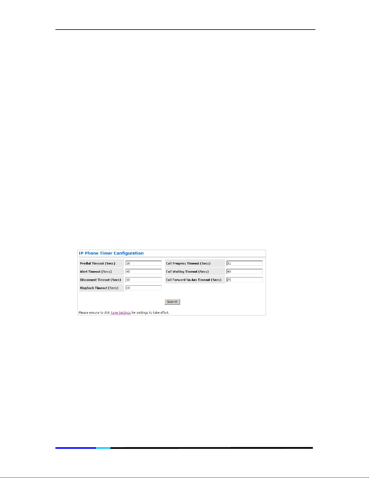
Timer Configuration
This page displays and configures timers used at the system level. This
section explains the various timers available for configuration. These
timers are not applicable for PSTN calls.
Figure 24 IP Phone Timer Configuration page
Predial Timeout (Secs): Enter the length of time in seconds the dial tone will be
generated once the phone has been lifted off hook. At the end of this period, if no
digits have been pressed, the ATA will start playing the Fast-Busy tone.
Call Progress Timeout (Secs): Enter the length of time in seconds the ATA will wait for
the initial response from the other end point once an outgoing call has been
made.
Alert Timeout (Secs): Enter the length of time in seconds the ATA will play the Ring
tone when an incoming call has arrived and the phone is on-hook. At the end of
this period, the ATA will automatically stop the ring and reject the call.
Call Waiting Timeout (Secs): Enter the length of time in seconds the Call Waiting
tone will be played when an incoming call arrives in the connected/held state. The
Page 46 of 72
Page 47
IP 200 User Manual
Call Waiting tone is played at an interval of 10 sec. for USA. It is configurable using
the Call Waiting tone parameters.
Disconnect Timeout (Secs):
will be played once a call has been disconnected by the remote-end. At the end
of this period, the Warble tone will be played until the user hangs up the phone.
Call Forward No Ans Timeout (Secs): Enter the length of time in seconds after which
the call will be forwarded when it is not answered.
RingBack Timeout (Secs): Enter the length of time in seconds ATA will wait while the
RingBack tone is being played for the final response from the other end point once
an outgoing call has been made and the initial response has been received.
Note: All Timeout parameters do not require a Save & Reboot to take effect.
Submit: Applies all the settings you did in this page.
Note: After clicking Submit to save page settings to system RAM, you must
permanently save the configuration and reinitialize the system as follows.
Save Settings: Click this link to go to the Save Settings / Reboot page. On the Save
Settings / Reboot page, click Save & Reboot to permanently save the settings to
system flash memory and to reinitialize the system to the new settings.
Enter the length of time in seconds the Fast-Busy tone
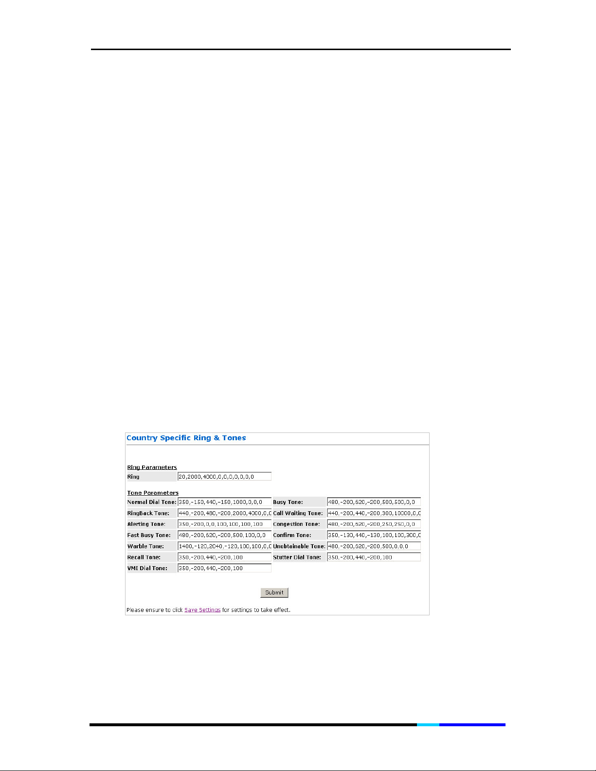
Ringtone Configuration
This page defines parameters for the various tones (ring, dial, busy,
ringback, etc.) generated by the ATA application. These parameters
may vary from country to country. Strongly recommend user to keep
these parameters by default.
Figure 25 Ring & Tone Configuration page
Page 47 of 72
Page 48

IP 200 User Manual
General Parameters
This page configures system-level parameters not related to the
selected line. This has four sections:
Service, and Codec Preference.
SIP Device, NAT Traversal, Special
Figure 26 General Parameters Continuation page
SIP Device: This section configures the following information:
Page 48 of 72
Page 49

IP 200 User Manual
• Local SIP Port: Enter the local SIP Port number on which ATA should listen for
messages. The range is 1 to 65535. The default port is 5060.
Media Base Port:
•
This parameter provides the base value from the media (RTP) ports that are
assigned for various lines and the different call-sessions that may exist within an
end-point. Odd port values are not recommended. If an Odd Value is entered,
the next higher even value is used as the Media Base Port. This is to conform to
the RFC specifications. The range is 1 to 65500. The default port is 5000.
NAT Traversal Parameters: This section configures for the NAT Traversal technique
support in ATA.
NAT Traversal Technique: Select USE STUN
•
behind a NAT enabled router and the router has no ALG for SIP, or NONE to
disable STUN (ATA is not to use STUN for NAT traversal). ATA also supports a
proprietary implementation of NAT traversal where the Service provider is
expected to provide some relay support. If NONE is selected, then based on
the responses received, the ATA will dynamically determine if the SIP Server
supports the proprietary implementation.
Note: Even when STUN is enabled, the ATA does an automatic detection of the
presence of SIP ALG and disables the use of STUN. This is to avoid some media
problems arising out of the behavior of some ALGs when STUN is used at the user
end.
Enter the Media Base Port (also known as RTP port) number.
to enable STUN (default) if the ATA is
• STUN Server: Enter the IP address or Domain Name of the STUN Server. The
default is 66.7.238.210. This field is applicable only if USE STUN is selected as the
NAT traversal technique.
• STUN Port: Enter the port number on which the STUN server listens for requests
from the STUN Client on ATA. The range is 1 to 65535. The default is 3478. This
field is applicable only if USE STUN is selected as the NAT traversal technique.
• Force Keep Alive: Only valid when STUN is not used. If STUN is not enabled, and
keep alive is still expected to be sent then select Yes otherwise select No.
• Keep Alive Period: The keep alive interval in seconds to be used when STUN is
not enabled.
Special Service: This section configures the following information:
• Auto Obtain Extension:
Auto Update Parameter:
•
Codec Preference: This section determines the order in which supported codecs will
be placed in a call setup message sent to any destination line. It also helps
determine the selected codec when a message indication for an incoming call is
received from the remote end with codec preference information.
• G711U: Select the priority 1 through 7 to be assigned to the G711U codec, or
NONE if the G711U codec is not to be used.
G711A:
•
NONE if the G711A codec is not to be used.
• G729A: Select the priority 1through 7 to be assigned to the G729A codec, or
NONE if the G729A codec is not to be used.
• G726-16: Select the priority 1 through 7 to be assigned to the G726-16 codec,
or NONE if the G726-16 codec is not to be used.
• G726-24: Select the priority 1 through 7 to be assigned to the G726-24 codec,
or NONE if the G726-24 codec is not to be used.
Select the priority 1 through 7 to be assigned to the G711A codec, or
Page 49 of 72
Page 50

IP 200 User Manual
• G726-32: Select the priority 1through 7 to be assigned to the G726-32 codec, or
NONE if the G726-32 codec is not to be used.
G726-40:
•
NONE if the G726- 40 codec is not to be used.
Note: If two codec types are assigned the same priority, then the priority is assigned
in the order as G711U > G711A > G729> G726-16> G726-24> G726-32> G726-40 in
the decreasing order of priority. For example, if 1, 2, and 2 is selected for G711U,
G711A, and G729, respectively, priority will be assigned as 1, 2, and 3 for G711U,
G711A, and G729, respectively.
• G726-16 Payload Number: Payload value for G726-16.
G726-24 Payload Number;
•
G726-32 Payload Number; Payload value for G726-32.
•
• G726-40 Payload Number; Payload value for G726-40.
Submit: Applies all the settings you did in this page.
Save Settings: Click this link to go to the Save Settings / Reboot page. On the Save
Settings / Reboot page, click Save & Reboot to permanently save the settings to
system flash memory and to reinitialize the system to the new settings.
Select the priority 1through 7 to be assigned to the G726-40 codec, or
Payload value for G726-24.
Address Book
This page allows for configuration of address book entries which can
be used for speed dial execution of calls.
Figure 27 Address Book page
Address Book Table:
This table displays the current address book.
Edit Address Book: User this portion to add a new entry or delete or edit an existing
entry.
• Display Name: Enter the Display Name for this address book entry.
Page 50 of 72
Page 51

IP 200 User Manual
• Number: The user phone number or name for this entry. This field is optional, if
the IP Address is specified. A phone number that can be reached through the
current configured proxy server can also be added as an entry in which case
the IP address/Domain name and the Port number fields are not necessary.
• IP Address/Domain Name: Enter the IP address or the domain name that
corresponds to this address book entry. If this field is left empty, then the User
number or name must be specified, in which case the current configured
proxy server for this endpoint will be used as the domain name.
• Port Number: Specify the SIP port number on which the remote end will receive
our call. This is useful when you want to specify a non-phone number entry,
where the call can be made directly without going through the configured
proxy server. When this field is not specified, the default SIP port of 5060 will be
assumed.
• Speed dial code: This refers to the index in the address book as well as the
speed dial entry code. This needs to be specified following *78 (or the
configured speed dial service code – see Section 2.4.2) to dial out the number
corresponding to this address book entry.
• Address Book Action: Select a drop-down option to manipulate the various
address book parameters for the entry index selected from the speed dial
code drop down box.
-DISPLAY ADDRESS BOOK: Select this item for the selected speed dial code
details to be displayed after clicking Submit. This is the default selection.
-ADD NEW ENTRY: Select this item to add a new address book entry after
clicking Submit
-EDIT: Select this item to overwrite the selected address book entry.
DELETE:
-
Select this item to delete the selected address book entry
Note: Up to ten Address Book entries can be added per endpoint.
Submit: Click Submit to save the settings on this page to system RAM and Flash also.
Note: Address book entries addition/deletion/editing do not need a Save and
Reboot. The changes are reflected immediately.
Route Table
The Route Table page displays the routing table and allows you to
manually enter a routing entry. The routing table displays the
Destination, Netmask, Gateway, and Interface columns. The
interface lo0 indicates the loop back interface; ppp1 indicates the
PPP interface. Gateway is the learned Gateway.
Page 51 of 72
Page 52

IP 200 User Manual
Figure 28 Route Table page
Route Table: This table displays the current route table.
System Default Gateway Configuration: This portion provides four options:
• None Allows you to choose to have no Default Gateway in the IP-PBX
• Auto Allows you to automatically set the Gateway (System Default) ·
Select Interface Allows you to select a Network Interface from a list. These
•
options let you associate the system default gateway to a network interface
whether static or dynamic. It also provides a way to fix the Default Gateway to
a dynamic Network Interface before the interface is established. ·
• Specify IP Allows you to manually enter a Default Gateway IP.
Execute: Save the setting and modification you did on this page by clicking
Execute.
Route Configuration
Destination: Allows you to enter the remote network or host IP address for the
•
static routing.
• Netmask: Allows you to enter the Subnet Mask for the static routing.
• Gateway: Allows you to enter the IP address of the gateway device that allows
the router to contact the remote network or the host for Specified IP or select
an Interface for the Gateway.
-Select Interface: Allows you to select a Network Interface from a list. This
option lets you associate the system default gateway to a network interface
whether static or dynamic. It also provides a way to fix the Default Gateway to
a dynamic Network Interface before the interface is established. ·
-Specify IP: Allows you to manually enter a Default Gateway IP.
• Add/ Delete: Select Add or Delete from the drop down menu to add a new
route or delete the specified route.
Page 52 of 72
Page 53
IP 200 User Manual
• Submit: Applies the settings you did on this page.
• Reset: Restores all setting in this page to default.
Save Settings:
Settings / Reboot page, click Save & Reboot to permanently save the settings to
system flash memory and to reinitialize the system to the new settings.
Manually Configured Routes: Displays the static route entries.
Click this link to go to the
Save Settings / Reboot
page. On the
Save
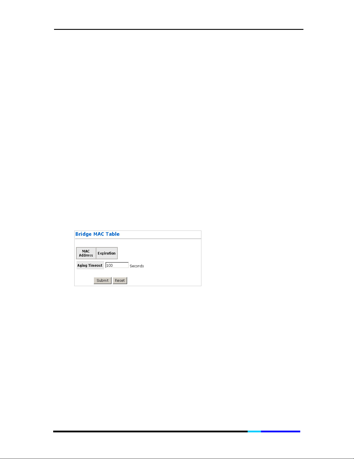
Bridge MAC Table
Network bridges operate at the physical network layer. The purpose
of a bridge is to connect two or more networks and enable packet
sharing between them. Bridges are different from routers because
they forward packets based on physical addresses, whereas routers
use IP address to forward packets. Bridges must learn all the physical
(MAC) addresses of the devices so it can forward the packets
reliably. The purpose of the Bridge MAC Table is to store and display
these bridge-recognized MAC addresses.
The Bridge MAC Table page shows the current Bridge MAC table. This
page contains information that is dynamic and will refresh every 8
seconds.
Figure 29 Bridge MAC Table page
Aging Timeout: This field allows you to enter the update period for the MAC table.
Have this number lower if you want a more frequent refresh rate. Range for Aging
Timeout field is 0 – 32767, default is 100.
Submit:
Reset: Restores all setting in this page to default.
Applies the settings you did on this page.
DMZ Configuration
Allows you to set a computer host as a 'neutral zone' between private
network of a company and the outside public network.
Page 53 of 72
Page 54

IP 200 User Manual
Figure 30 DMZ Configuration page
DMZ: A DMZ (De-Militarized Zone) is added between a protected network and an
external network, in order to provide an additional layer of security. When there is a
suspected packet coming from WAN, the firewall will forward this packet to the
DMZ host.
DMZ Host IP: The IP address of the DMZ host viewable at the WAN (external) side.
Apply: Applies the settings you did on this page.
Reset: Restores all setting in this page to default.
Save Settings: Click this link to go to the Save Settings / Reboot page. On the Save
Settings / Reboot page, click Save & Reboot to permanently save the settings to
system flash memory and to reinitialize the system to the new settings.
SNTP Configuration
Simple Network Time Protocol is an efficient method of obtaining the
time from a Time Server.
Figure 31 SNTP Configuration page
Time Zone: This specifies the time zone (geographical location).
Daylight Saving Time: You can select yes to activate Daylight Savings Time.
User defined Time server: This is the time server from which the HNP Router retrieves
the time.
Save Settings: Click this link to go to the Save Settings / Reboot page. On the Save
Settings / Reboot page, click Save & Reboot to permanently save the settings to
system flash memory and to reinitialize the system to the new settings.
Page 54 of 72
Page 55

IP 200 User Manual
Miscellaneous Configuration
Allows you to set miscellaneous configurations, like HTTP, FTP, TFTP and
so on.
Figure 32 Miscellaneous Configuration page
HTTP Server Access:
be accessed.
• All: When this field is checked, it allows both WAN and LAN access to the Web
pages. This is the system default.
• Restricted LAN: This field allows the Web pages access from LAN side.
• Restricted WAN Specified IP & Subnet Mask: This field allows the Web access
from WAN side with a specify IP and subnet mask.
HTTP Server Port: This field allows you to specify the port of the Web access. For
example, when it is changed to 8080, the HTTP server address for the LAN side is
http://10.0.0.2:8080. Range for HTTP Server port is 0 – 32767, default value is 80.
FTP server: This field allows you to enable or disable the FTP server connection.
System default is Enabled.
• Disable WAN side FTP access: This will disable WAN side access to the FTP
server.
TFTP server: This field allows you to enable or disable the TFTP connection. System
default is Disabled.
This field allows you to configure where these Web pages can
Page 55 of 72
Page 56

IP 200 User Manual
IGMP Proxy: This is the global setting for IGMP Proxy. If it is enabled, then the
enabled IGMP Proxy on WAN PVCs will be working. Otherwise, no WAN PVC can
have IGMP Proxy working on it. System default is Disabled.
PPP Half Bridge: Not applicable for router application.
PPP reconnect on WAN access: If enabled, the PPP session will automatically
establish a connection when a packet tries to access the WAN. System default is
Disabled.
Connect PPP when ADSL link is up: Not applicable for router application.
Apply: Applies the settings you did on this page.
Reset: Restores all setting in this page to default.
Save Settings:
Settings / Reboot page, click Save & Reboot to permanently save the settings to
system flash memory and to reinitialize the system to the new settings.
Click this link to go to the
Admin Username/Password Configuration
This page allows you to set the password for administrator.
Save Settings / Reboot
page. On the
Save
Figure 33 Admin Username/Password Configuration page
The Admin password is same as the FTP password, so it must have at least 8characters for the FTP to work. The Admin password can be up to 65 characters
(excluding ‘&’).
Reset to Default
Allows you to restore all your settings to factory default by clicking
Restore.
Page 56 of 72
Page 57
IP 200 User Manual
Figure 34
Restore Settings page
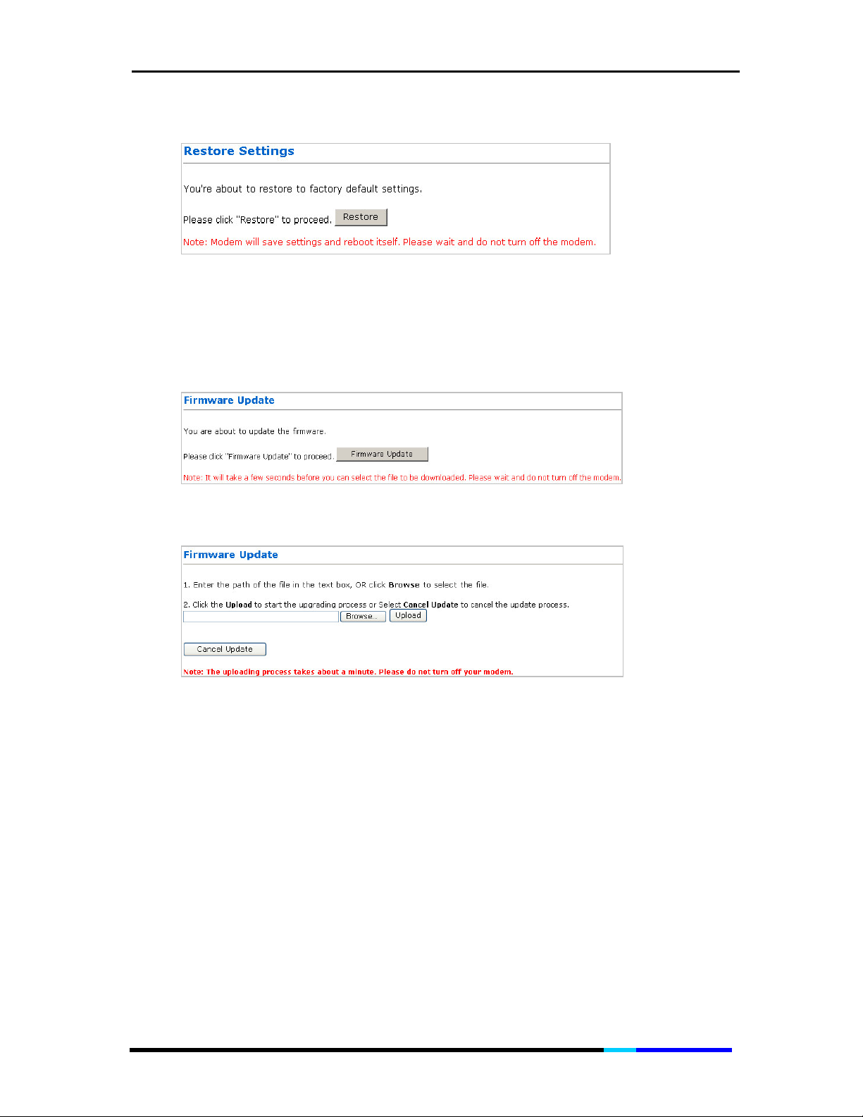
Firmware Update
The Firmware Update page allows you to update the firmware for
your IP Phone.
Figure 35 Firmware Update page 1
Click Firmware Update to enter the following page:
Figure 36 Firmware Update page 2
Follow the two steps above to do the update:
1. Enter the path of the file in the text box, or click Browse to select the file.
2. Click the Upload to start the upgrading process or Select Cancel Update to
cancel the update process.
Note: The uploading process takes about a minute. Please do not turn off your
modern.
Save / Reboot
Allows you to save the settings and reboot your IP phone or reboot
your IP phone without saving settings by clicking the corresponding
buttons.
Page 57 of 72
Page 58

IP 200 User Manual
Figure 37 Save Settings / Reboot page
Save & Reboot: Click this button to save settings and reboot the IP Phone.
Reboot Only: Click this button to reboot the IP Phone without saving settings.
Page 58 of 72
Page 59

IP 200 User Manual
Back
Disable
Disable
Save
&Reset
User
Time Set
Yes
Yes
6 Functions
6.1 Menu Structure
New
Enable
Enable
Select
Del
Cancel
No Answer
Unconditional
Busy
Name
Home
Cell
SIP Config
WAN Config
DHCP
Mac address
LAN Config
DNS proxy
ADD DNS Server
Date Set
Page 59 of 72
Ring Tone
Ring Volume
VOIP Settings
Network Settings
Date/Time
Contrast
SW Version
Factory Setting
No
No
Page 60

IP 200 User Manual
Disable
Enable
Set Monitor1 Num
Disable Monitor1
Set Monitor2 Num
Disable Monitor2
6.2 Making and Answering Calls
To Place a Call
You can place a call by:
• Dialing and lifting the handset immediately, or
• Dial and connect the headset, press the Headset, or
• Dial and press the Speakerphone.
At the end of the call, hang up the phone to disconnect. For headset
or speaker, you must also push the button to end the call.
Note: You can dial the number after you lift the handset or press the
Speakerphone or press the Headset if you need, but you won't be
able to correct any mistakes if you do it in this way.
To Answer or Reject a Call
When the phone rings, lift the handset or press the Speakerphone
•
or press Headset press the OK soft key to answer the call.
• Otherwise, press Rej soft key to reject the call.
To Redial a Call
• In standby mode, press the Redial soft key to redial the last dialed
number. Or
Page 60 of 72
Page 61

IP 200 User Manual
• After Lifting the handset or pressing Speakerphone/ Headset key,
press the Redial soft key to redial the last dialed number
To Mute / Un-mute a Call
• Mute the handset, headset or speakerphone by pressing the Mute.
This prevents the person on the active call from hearing what you
or someone else in the room is saying.
• To cancel the Mute function, press the Mute again.
Earpiece Volume / Speakerphone Volume
• During a call, you just press Left & Right Scroll to adjust the volume
of the earpiece or the volume of the speakerphone (1-6 level).
Switching Between the Handset/Headset/Speakerphone on a Call
• Any of the audio devices can be used during a call. Only one
device at a time can be used.
• The handset can be on the hook when using the speakerphone or
headset function. If switching from the handset, make sure the
speakerphone or headset button is pressed before placing the
handset back on the hook.
6.3 Handling Calls
IP200 allows you to handle calls with various manners, you can park
the call, transfer the call, hold the call, make a conference call, pick
up the call on another phone and so on.
To Transfer a Call
To transfer a selected call to another number in one of two ways:
• Blind transfer—immediately redirects the call without allowing you
to speak to the transfer recipient (the person to whom you are
transferring the call).
• Attended transfer—Redirects the call after first allowing you to
speak to the transfer recipient.
Page 61 of 72
Page 62

IP 200 User Manual
1.
To initiate a transfer, press the Trans soft key during an active call.
This places the first call on hold and you will hear a dial tone.
Dial the second person’s telephone number. When the second
2.
person answers, hand up if you make Blind Transfer or you can
have a private conversation with the second person without the
first person hearing it if you make Attended Transfer.
To Make a Conference Call
1.
To initiate a conference call, press the conf soft key during an
active call.
2.
The first call is placed on hold, and you will hear a dial tone. Dial
the second person’s telephone number.
To start the conference call, press the Hold, all three parties will be
3.
participating in a conference call.
To Park a call
1. To initiate Call Park, press the
Park
soft key during an active call,
this places the call on hold, and you will hear the phone assign
you a number (up to 3 digitals).
2. You will retrieve the call from another phone or from the same
phone by dialing the assigned number.
It will not work if the phone placing the call on Park has a busy
diversion (you must hear a busy signal to retrieve the call).
Consultation Hold
1. To initiate a Consultation Hold, press C.Hold soft key during an
active call;
2. The first call is placed on hold, and you will hear a dial tone. Dial
the second person’s telephone number.
3. When the second party is connected, press
between speaking to first party and second party.
Hold
to toggle
Page 62 of 72
Page 63

IP 200 User Manual
It is similar to Conference Call, but as a host you can only connect to
one party, while the other party is put on hold. (The two parties
cannot be both connected at the same time.)
To Hold a Call
• Press the Hold button to put the active call on hold.
If there is another incoming call, you can now answer the 2nd call,
•
press Hold button again to retrieve the first call.
To Transfer call or make conference call with Monitored numbers
1. To initiate this function, press the corresponding line key of the
monitored number displayed on the LCD during an active call;
2. Press the Up & Down to select Blind Transfer / Attended Transfer /
Conference
;
3. Press Select soft key.
To Pick up a Call
• When there is an incoming call in your group, press P.up soft key to
pick up the call.
If there is more than one incoming call involved when you initiate call
pickup, the first unanswered call will ring at your phone.
6.4 Phonebook
Up to 200 records could be stored in each IP phone Phonebook.
Each record can store up to 30 digits, and names of up to 20
characters.
To Check and Dial the record
1. In standby mode, Press the Phbk soft key to enter the phonebook
mode.
2. When one of the records is selected, press
the details, then you can press Call soft key to dial the number;
Page 63 of 72
Select
soft key to view
Page 64

IP 200 User Manual
To Add New Number into Phonebook
1. Press the Add soft key to initiate Add under phonebook mode;
2. Press the line key for the corresponding option you would like to
edit.
3. Enter the Name or Number use the Clear soft key to delete the
incorrect character or number. Then press OK soft key to confirm.
4. Press Save soft key to save the entry.
Note: When your phonebook is empty, select
record.
If you wish to check, dial, edit, delete the records, and check the
memory, this is easily done here.
6.5 Call Logs
You must subscribe to Caller ID service from your service provider to
use this feature.
Call Logs store information related to Received calls, Missed calls and
Dialed calls. You phone can store up to a maximum of 30 calls,
consisting of 10 Received, Missed and Dialed calls respectively.
To Check Call Records
1. In standby mode, press the first line key to enter the call lists;
2. Press Up & Down scroll to select the call type Received Calls /
Dialed Calls / Missed Calls, then press the Select soft key to
confirm;
soft key to add a
New
3. Use More soft key to display the Show tab. Then press the Show
soft key to check the call records;
If you wish to dial, save, delete the call logs, this is easily done here.
Page 64 of 72
Page 65

IP 200 User Manual
6.6 Call Settings
To Set DND Function
DND is short for “ Do Not Disturb”. With this function activated, the
incoming calls will no longer come to the phone and you will be
completely undisturbed by the phone.
1. Use the More soft key to display the DND tab;
2. Press the DND soft key and use the Up & Down scroll key to select
Enable / Disable, this allows you to initiate the function or not;
3. Press the Select soft key to confirm.
To Set Follow-me
With the Follow-Me function, your contacts can reach you wherever
you are. And you can log into the phone system from different
location with the Use Follow-me enabled in another IP phone under
same network.
1. Use the More soft key to display the Follo tab;
2. Press the Follo soft key and use the Up & Down scroll key to select
Enable / Disable,
3. Press the Select soft key to confirm.
To Set Use Follow-me
1. Press the Here soft key and key in the extension number your call
follows, press the Del soft key to delete the digit;
2. Press the Select soft key to confirm.
To Set Call Forwarding
There are three call forwarding options which allow you to redirect all
incoming calls from your IP Phone to another extension number:
Unconditional, Busy and No answer.
this allows you to initiate the function or not;
• Unconditional: Forward all calls to a specified Ext No.
Page 65 of 72
Page 66

IP 200 User Manual
• Busy: Forwards calls when phone is busy.
• No answer: Forwards calls if there's no answer.
1. Use the More soft key to display the C.Fwd tab;
2. Press the C.Fwd soft key and press the Up & Down scroll key to
select No Answer / Unconditional / Busy;
3. Press the Select soft key and press the Up & Down scroll key to
select Enable / Disable, this allows you to initiate the function or
not;
4. If Enable is selected, key in the extension number and press Select
soft key. Press the Del soft key to delete the incorrect digit.
Voice Mail Boxes
Your phone administrator chooses the voice mail system that your
phone uses. For information on how to use your voice mail system,
refer to the documentation that came with it. For example, if your
administrator configured your phone system to work with Aztech
Unity, you would refer to the Aztech Unity documentation about
working with your voice mail.
To Disable / Enable Voicemail boxes
1. Use the More soft key to display the VMSet tab;
2. Press the VMSet soft key and press the Up & Down scroll key to
select Enable / Disable, this allows you to initiate the function or
not;
3. Press the Select soft key to confirm.
To Listen to Voicemail
• In standby mode, press the second line key to listen to the voice
mail.
To Set Monitor Function
With phone monitoring, you can monitor the status of up to 2
programmed phones in your network. Through the alerts, you can
Page 66 of 72
Page 67

IP 200 User Manual
view information about the phone’s reachability, such as a phone’s
busy status.
Your IP 200 indicates the monitored phones` status by providing the
following cues:
The red light of the corresponding
Line key remains lit
The yellow light of the
corresponding line key remains lit
The monitored phone is in
a call.
Your IP200 is making call
with the monitored phone.
No light activity The monitored phone is
free to contact.
To set monitor number
1. Use the More soft key to display the Moni tab;
2. Press the Moni soft key to enter the Monitor Number page;
3. Press the Up & Down to select
Set Monitor 1 Num / Set Monitor2
Num;
4. Press
Select
soft key to confirm your choice, and key in the
extension number;
5. Press OK soft key to save the number.
To disable the monitor number
1. Repeat the step 1~2 above;
2. Press the Up & Down to select Disable Monitor 1 / Disable Monitor 2;
3. Press Select soft key to confirm your choice.
To set Call Redirect
Allows you to redirect all incoming calls from your IP Phone to PSTN,
your IP phone must work with a IP-PBX which supports this function.
1. Use the
More
soft key to display the
C.ReD
tab;
Page 67 of 72
Page 68

IP 200 User Manual
2. Press the C.ReD soft key;
3. Press the Up & Down to select Enable /Disable, this allows you to
initiate the function or not;
4. Press Select soft key to confirm your choice, if Enable is selected,
key in the extension number and press OK soft key to save it.
Page 68 of 72
Page 69

IP 200 User Manual
7 Troubleshooting
If your IP phone does not operate as you expect, check the following
points before reporting a fault to your phone services manager:
1) No dial tone
• Check that the IP phone is plugged in to the IP network;
• Check that the power supply is plugged in and switched on.
2) Phone does not ring
• Handset has not been properly hooked;
• Your calls are diverted (you hear a special tone when you lift the
handset and the upper line of the display usually shows the
telephone number to which calls are diverted);
• Do not disturb is set;
Follow me has been activated;
•
• The ringing volume is too low.
3) Cannot dial an external number
• You do not have the privilege. Contact your system administrator
to check.
4) The system does not recognize your User ID or your PIN
• Try to log in again to confirm that you did not make a mistake
when you entered your User ID and PIN.
• If you receive the error message again, contact your system
administrator to check that you have the correct User ID and PIN.
5) LCD display appears to have rolling lines or a wavy pattern
It might be interacting with certain types of older fluorescent lights
•
in the building. Moving the phone away from the lights, or
replacing the lights.
Page 69 of 72
Page 70

IP 200 User Manual
6) Phone resetting
• This lost connection and make the phone reset can be due to any
network connectivity disruption, including cable breaks, switch
outages, and switch reboots.
7) Cannot change the phone configuration.
• You must unlock the network configuration options before you
can configure them.
Page 70 of 72
Page 71

IP 200 User Manual
Glossary of Terms
ATA
Analog Telephony Adaptor
DID
Direct Inward Dial. A specially configured phone line from the telephone
company that allows for dialing inside a company directly without having to go
through an attendant.
SIP
Session Initiation Protocol, SIP is an Internet Engineering Task Force (IETF) standard
protocol for initiating an interactive user session that involves multimedia elements
such as video, voice, chat, gaming, and virtual reality.
ADSL
Asymmetric Digital Subscriber Line: Modems attached to twisted pair copper
wiring that transmit from 1.5 Mbps to 9 Mbps downstream (to the subscriber) and
from 16 kbps to 800 kbps upstream, depending on line distance.
DNS
Domain Name System (or Service or Server), an Internet service that translates
domain names into IP addresses
DHCP
The Dynamic Host Configuration Protocol (DHCP) is an Internet protocol for
automating the configuration of computers that use TCP/IP. DHCP can be used to
automatically assign IP addresses, to deliver TCP/IP stack configuration parameters
such as the subnet mask and default router, and to provide other configuration
information such as the addresses for printer, time and news servers.
IP
Internet Protocol. A packet-based protocol for delivering data across networks.
Page 71 of 72
Page 72

IP 200 User Manual
VoIP
Voice over IP (also called VoIP, IP Telephony, and Internet telephony) refers to
technology that enables routing of voice conversations over the Internet or any
other IP network. The voice data flows over a general-purpose packet-switched
network, instead of the traditional dedicated, circuit-switched voice transmission
lines.
NAT
Network Address Translation. A networking protocol that allows network of private
IP address to be set up using a single real IP address.
PPPoE
Point-to-Point Protocol over Ethernet, is a network protocol for encapsulating PPP
frames in Ethernet frames. It is used mainly with cable modem and DSL services.
STUN
Simple Traversal of UDP over NATs, is a network protocol allowing clients behind
NAT (or multiple NATs) to find out its public address, the type of NAT it is behind and
the internet side port associated by the NAT with a particular local port. This
information is used to set up UDP communication between two hosts that are both
behind NAT routers. The protocol is defined in RFC 3489. STUN will usually work well
with non-symmetric NAT routers.
MAC address
Media Access Control address, is a unique code assigned to most forms of
networking hardware. The address is permanently assigned to the hardware, so
limiting a wireless network's access to hardware -- such as wireless cards -- is a
security feature employed by closed wireless networks.
Page 72 of 72
 Loading...