

Page 1

FG7008GR(AC)
DUAL BAND WIRELESS-AC
MU-MIMO GIGABIT ROUTER
Page 2

User Manual
Page 2 of 88
Page 3

User Manual
Page 3 of 88
© Copyright 2014 All rights reserved.
No part of this document may be reproduced, republished, or retransmitted in any form or
by any means whatsoever, whether electronically or mechanically, including, but not limited
to, by way of photocopying, recording, information recording, or through retrieval systems
without the express written permission. We reserve the right to revise this document at any
time without the obligation to notify any person and/or entity. All other company or product
names mentioned are used for identification purposes only and may be trademarks of their
respective owners.
LIMITATION OF LIABILITY AND DAMAGES
THE PRODUCT AND THE SOFTWARES WITHIN ARE PROVIDED "AS IS," BASIS. THE MANUFACTURER
AND MANUFACTURER’S RESELLERS (COLLECTIVELY REFERRED TO AS “THE SELLERS”) DISCLAIM
ALL WARRANTIES, EXPRESS, IMPLIED OR STATUTORY, INCLUDING WITHOUT LIMITATION THE
IMPLIED WARRANTIES OF NON-INFRINGEMENT, MERCHANTABILITY OR FITNESS FOR A
PARTICULAR PURPOSE, OR ANY WARRANTIES ARISING FROM COURSE OF DEALING, COURSE
OF PERFORMANCE, OR USAGE OF TRADE. IN NO EVENT WILL THE SELLERS BE LIABLE FOR
DAMAGES OR LOSS, INCLUDING BUT NOT LIMITED TO DIRECT, INDIRECT, SPECIAL WILLFUL,
PUNITIVE, INCIDENTAL, EXEMPLARY, OR CONSEQUENTIAL, DAMAGES, DAMAGES FOR LOSS OF
BUSINESS PROFITS, OR DAMAGES FOR LOSS OF BUSINESS OF ANY CUSTOMER OR ANY THIRD
PARTY ARISING OUT OF THE USE OR THE INABILITY TO USE THE PRODUCT OR THE SOFTWARES,
INCLUDING BUT NOT LIMITED TO THOSE RESULTING FROM DEFECTS IN THE PRODUCT OR
SOFTWARE OR DOCUMENTATION, OR LOSS OR INACCURACY OF DATA OF ANY KIND,
WHETHER BASED ON CONTRACT, TORT OR ANY OTHER LEGAL THEORY, EVEN IF THE PARTIES
HAVE BEEN ADVISED OF THE POSSIBILITY OF SUCH DAMAGES. THE ENTIRE RISK AS TO THE
RESULTS AND PERFORMANCE OF THE PRODUCT OR ITS SOFTWARE IS ASSUMED BY CUSTOMER.
BECAUSE SOME STATES DO NOT ALLOW THE EXCLUSION OR LIMITATION OF LIABLITY FOR
DAMAGES, THE ABOVE LIMITATION MAY NOT APPLY TO THE PARTIES. IN NO EVENT WILL THE
SELLERS’ TOTAL CUMULATIVE LIABILITY OF EACH AND EVERY KIND IN RELATION TO THE
PRODUCT OR ITS SOFTWARE EXCEED THE AMOUNT PAID BY CUSTOMER FOR THE PRODUCT.
Page 4

User Manual
Page 4 of 88
Contents
About the Router ......................................................................................................... 6
Requirements ................................................................................................ 8
Package Contents ....................................................................................... 8
Device Design ............................................................................................... 9
Front Panel ..................................................................................................... 9
Back Panel ................................................................................................... 10
Getting Started ........................................................................................................... 11
Planning Your Network .............................................................................. 11
Remove or Disable Conflicts ..................................................................... 13
Internet Sharing, Proxy, and Security Applications ............................... 13
Configuring TCP/IP Settings ....................................................................... 14
Configuring Internet Properties ................................................................ 14
Removing Temporary Internet Files .......................................................... 15
Setup the Device ........................................................................................ 16
The Web User Interface ............................................................................................. 17
Accessing the Web User Interface .......................................................... 17
Web User Interface Modes ....................................................................... 17
Switching Modes ......................................................................................... 17
The Side Panel Feature .............................................................................. 17
Basic Mode ................................................................................................................. 18
Menus ........................................................................................................... 18
Quick Setup ................................................................................................. 19
Network Configuration .............................................................................. 23
Device Status .............................................................................................. 26
Statistics ........................................................................................................ 28
Firewall .......................................................................................................... 30
Device Administration ................................................................................ 39
Advanced Mode ....................................................................................................... 42
Menus ........................................................................................................... 42
Device Info .................................................................................................. 43
Page 5

User Manual
Page 5 of 88
Statistics ........................................................................................................ 45
Advanced Setup ........................................................................................ 47
Security ......................................................................................................... 69
Wireless ......................................................................................................... 75
Diagnostics .................................................................................................. 80
Management .............................................................................................. 81
Safety Precautions ..................................................................................................... 86
Page 6

User Manual
Page 6 of 88
About the Router
The consistent growth in the number of wireless devices one has at home has
been considered as one of the major challenges a router should be able to
accommodate, not just in providing Wi-fi speed, but also in providing a
consistently impressive wireless performance and superb wireless transfer rates
no matter how much the number of wireless devices keep on adding up.
With careful consideration to these ever growing need, Aztech developed
the FG7008GR(AC), a Dual Band Wireless-AC 2400Mbps MU-MIMO Gigabit
Router, a device that offers extreme wireless transfers rates and an ultimate
wireless performance utilized further by the latest Multi-User MIMO (MU-MIMO)
Technology.
Developed Primarily for Fibre via ONT Connectivity. Ultimately designed
and maximized for Fibre connectivity, the FG7008GR(AC) is equipped
with a Gigabit WAN port supremely built for FTTH via ONT connection
optimization.
The Powerhouse : FG7008GR(AC). Innovated with the latest available
chipset BCM63139 in conjunction with QuantennaTM 4T4R 5.0GHz Multi-
User MIMO Wireless AC and Broadcom BCM43602 3T3R 2.4GHz, the
FG7008GR(AC) allow customers to enjoy the full benefits of the
802.11ac wireless standard by delivering unparalleled network
performance to all 5.0GHz wirelessly connected devices
SIMULTANEOUSLY. Multi-User MIMO technology enhances the MIMO
System when there are multiple devices connected to the 5.0GHz
wireless network.
Concurrent Dual Band Wireless Connectivity. The FG7008GR(AC) has a
Dual Band feature which enable users to connect their dual band
wireless devices in either (1) the 2.4GHz band with wireless speeds of up
to 600Mbps (Turbo QAM), and (2) the faster 5.0GHz wireless frequency
band with extreme wireless speeds of up to 1800Mbps, a great partner
for High-Definition A/V streaming, and other bandwidth hungry
applications.
Page 7

User Manual
Page 7 of 88
USB 3.0 Ports for Enhanced User Experience. Equipped with two (2) USB
3.0 ports, customers may now enjoy a faster method of sharing a
connected storage’s files throughout the network.
Connect Easily using Wi-Fi Protected Setup (WPS). Instead of
connecting conventionally to your wireless network, the
FG7008GR(AC)’s WPS support enables users to easily connect their
wireless devices to the gateway with a simple press of the WPS button.
Easy Installation and Setup. Involving zero complexity in its setup, the
FG7008GR(AC) uses an intuitive design making the device easy to
setup and use. Easily manage various router features through an OS
Independent Web User Interface that users can easily access after
setting up the device.
Page 8

User Manual
Page 8 of 88
Requirements
Your computer must meet the following minimum requirements.
Any operating system can be used
Web Browser
233MHz processor (or higher)
Ethernet network adapter
An active ONT for Fibre connection
Package Contents
Package contents are listed below. For any missing items, please contact
your dealer immediately. Product contents vary for different models.
FG7008GR(AC)
Ethernet cable (Yellow)
12V 3A DC Power Adapter
Easy Start Guide
Warranty Policy
Note: You may also download the Quick Installation Guide, and the User
Manual by visiting this link: http://www.aztech.com/support/
Page 9

User Manual
Page 9 of 88
LED STATUS DESCRIPTION
POWER Off No power is supplied to the
device
Green (Steady) Connected to a Power Supply
Red (Steady) Error on the device
ETH LAN 1-4 Off No Ethernet connection
Green (Steady) Connected to an Ethernet
device
Green (Blinking) Corresponding port is currently
transmitting / receiving data.
5.0GHz/2.4GHz Off There is no device connected
wirelessly
Green (Blinking) Wireless interface is actively
transmitting / receiving data.
Green (Steady) There is a device connected
wirelessly
USB Off There is no USB device
connected to
the corresponding USB port.
On A USB device connected to the
corresponding USB port.
IPTV OFF IPTV interface is not up
Green (Steady) IPTV Interface is up and Set-top
box is active
Red (Steady) IPTV is up and Set-top box is
inactive/or not connected
BROADBAND Green (Blinking) Establishing ONT Signal
Green (Steady) Connectivity to the ONT is
established
WAN Ethernet interface is
connected
OFF There is no connectivity to the
ONT
INTERNET OFF No internet
Red (Steady) Authentication Failed
Green (Steady) Internet interface is up
WPS Green (Steady) WiFi Protected Setup has been
Established
Green (Blinking) Ongoing / Active WiFi
Protected Setup process
Device Design
Front Panel
Page 10
User Manual
Page 10 of 88
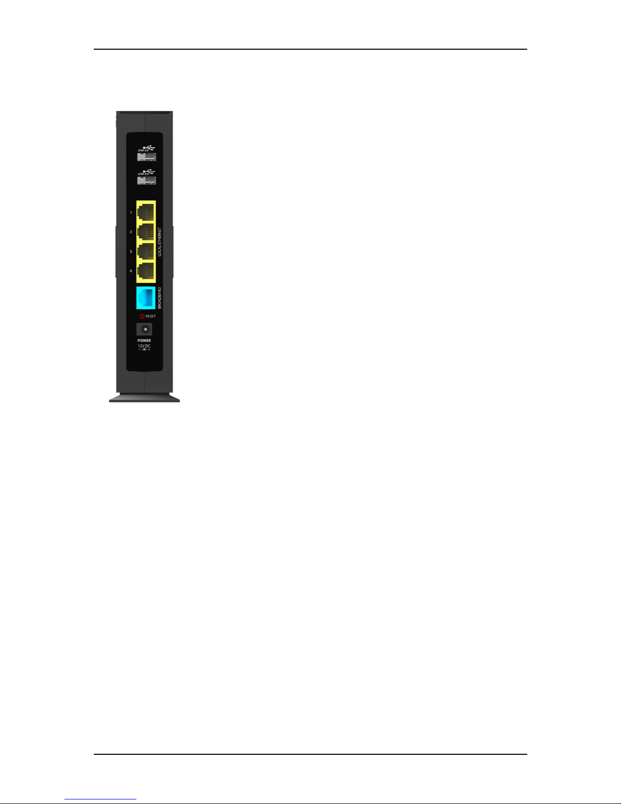
PORT/BUTTON DESCRIPTION
USB 1 & 2 USB 3.0 Ports for USB devices such as printers and USB
external hard drives
ETHERNET 1 - 4 Connecting computers and other Ethernet devices
ETHERNET WAN For WAN connection through an Ethernet cable
RESET To reset the modem to the factory default configuration
POWER 12V 3A Adapter input
Back Panel
Page 11
User Manual
Page 11 of 88
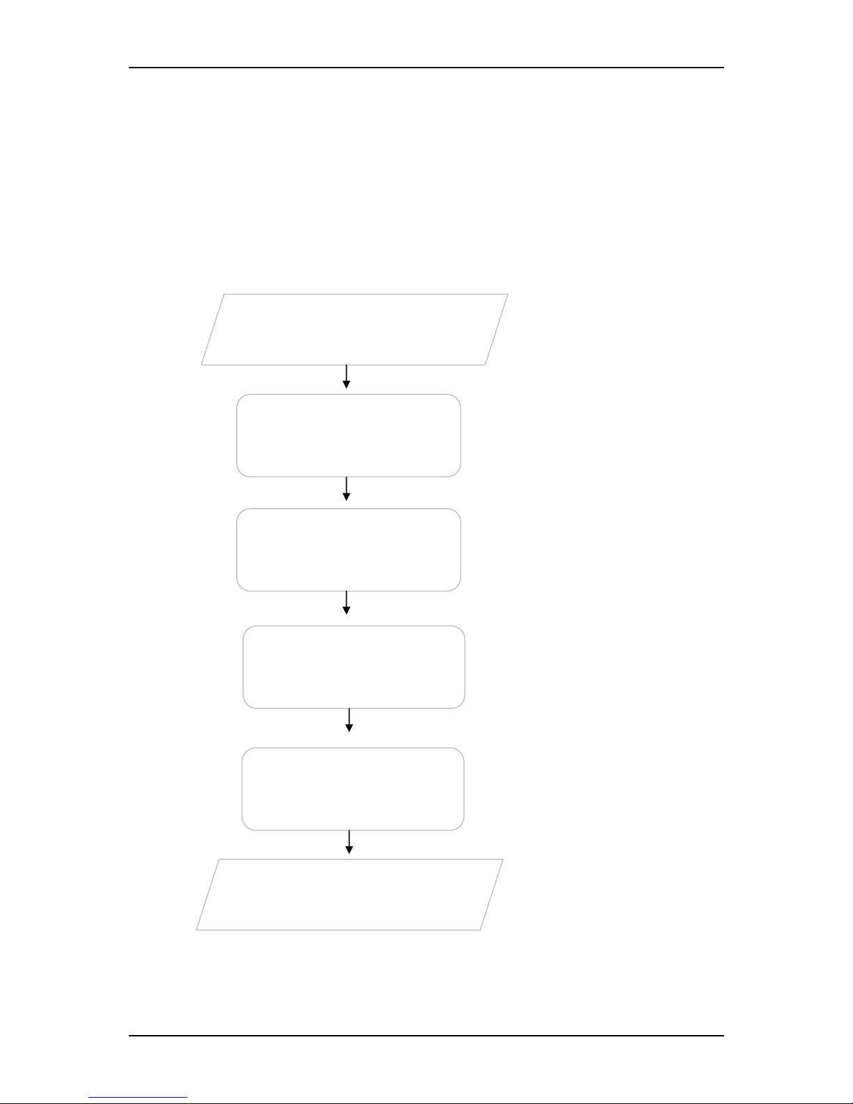
Getting Started
Setting up the device is easy. The diagram below provides an outline of the
steps needed in order to complete the installation. Brief descriptions appear
beside each step. Detailed instructions are provided in the subsequent
pages.
You may need to check some
settings or disable some
applications before
proceeding with the
installation.
Connect the telephone
cables, Ethernet cables, and
power adapter.
For Singapore Fibre
Residential Customers, the
FG7008GR(AC) auto-detects
the configuration of your fibre
connection. internet.
You may see the suggested
network setup.
Remove/
Disable
Plan your Network
Ready to Use
Setup the
Router
Connect to
the
Web User Interface
(Optional)
You may easily configure
various router features through
the Web User Interface
Page 12
User Manual
Page 12 of 88
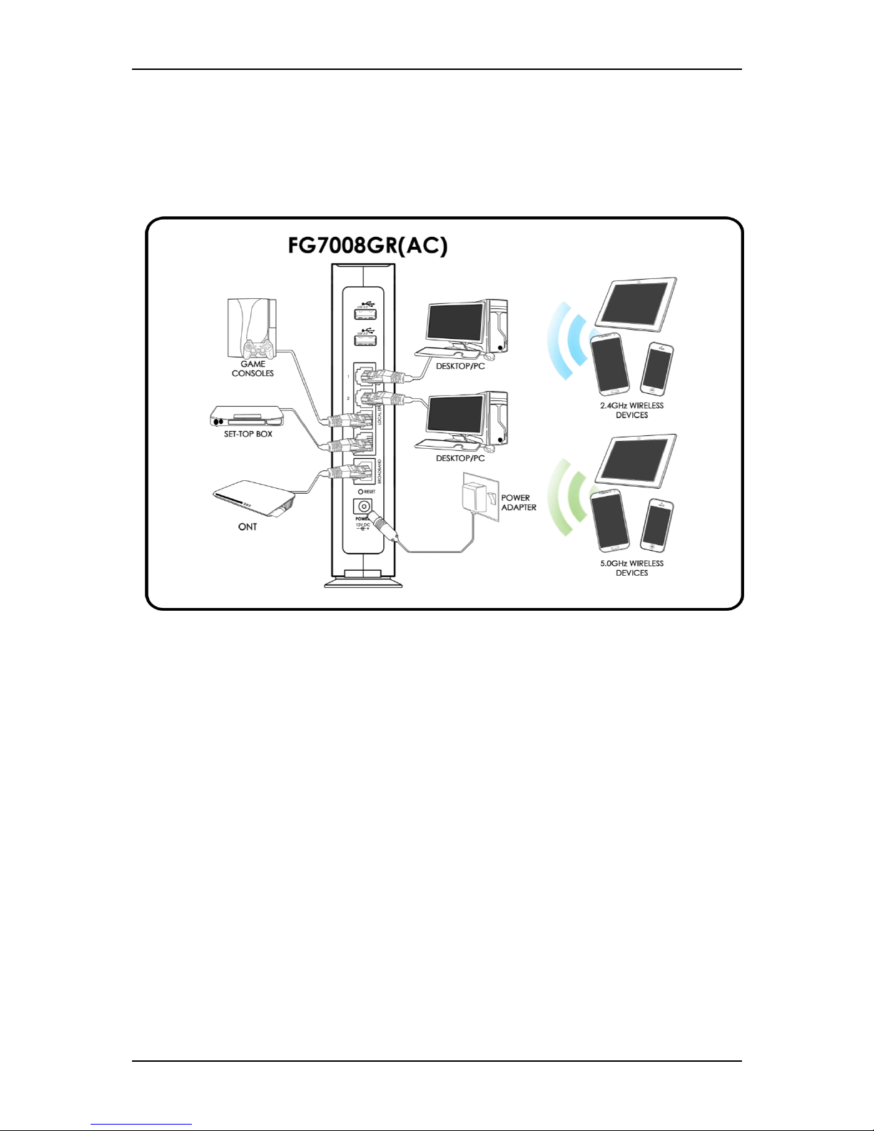
Planning Your Network
Before moving ahead to setup your network, it is a good idea to draw out a
network diagram to help identify your network devices and plan out how to
connect these devices.
Each port in the router can be used for different connections. For example:
Ethernet 1 – Set-top Box
Ethernet 2 – Game Console
Ethernet 3 – Dad’s Computer
Ethernet 4 – Mom’s Computer
Ethernet WAN – ONT
To create a network diagram:
For wireless devices, identify the wireless devices you want to include in
the network
For wired devices, identify which router port you want to use for each
device.
Page 13

User Manual
Page 13 of 88
Remove or Disable Conflicts
To ensure that the router installation moves on smoothly, you need to remove
or disable conflicts that may interfere with the installation. Probable conflicts
may include:
Internet sharing applications
Proxy software
Security software
TCP/IP settings
Internet properties
Temporary Internet files
Internet Sharing, Proxy, and Security Applications
Internet sharing, proxy software, and firewall applications may interfere with
the router installation. These should be removed or disabled before starting
the installation.
If you have any of the following or similar applications installed on your
computer, remove or disable them according to the manufacturer’s
instructions.
Internet Sharing
Applications
Proxy Software
Security Software
Microsoft Internet Sharing
WinGate
Symantec
WinProxy
Zone Alarm
Page 14

User Manual
Page 14 of 88
Configuring TCP/IP Settings
Check if your computer uses the default TCP/IP settings.
To check the TCP/IP properties:
1. Select Start > Run. The Run dialog box would appear.
2. Enter control ncpa.cpl on the input box, and then click the OK button.
This would open the Network Connections window in your computer.
3. Right-click LAN and then select Properties. The Local Area Connection
Properties dialog box would appear.
4. Select Internet Protocol (TCP/IP) and then click Properties. The Internet
Protocol (TCP/IP) dialog box would appear.
5. Select Obtain an IP address automatically.
6. Click the OK button to close the Internet Protocol (TCP/IP) dialog box.
7. Click the OK button to close the Local Area Connection Properties
dialog box.
Configuring Internet Properties
To set the Internet Properties:
1. Select Start > Run. This opens the Run dialog box.
2. Enter control inetcpl.cpl and then click OK to open the Internet
Properties window.
3. Click on the Connections tab.
4. On the Dial-up and Virtual Private Network settings pane, select Never
dial a connection.
5. Click OK to close Internet Properties.
Page 15

User Manual
Page 15 of 88
Removing Temporary Internet Files
Temporary Internet files are files from Web sites that are stored in your
computer. Delete these files to clean the cache and remove footprints left by
the Web pages you visited.
To remove temporary Internet files:
1. Select Start > Run to open the Run dialog box.
2. Enter control and then click the OK button to open the Control Panel.
3. Double-click Internet Options.
4. On the Internet Options window, in the Temporary Internet Files pane,
click Delete Cookies.
5. Click Delete Files.
6. Click OK to close Internet Properties.
Page 16
User Manual
Page 16 of 88
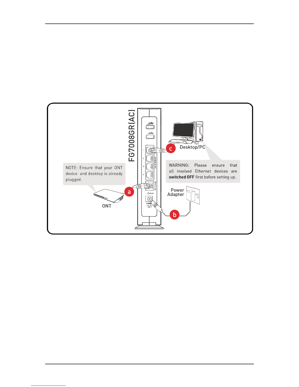
Setup the Device
When installing the router, find an area where there are enough electrical
outlets for the router, the main computer, and your other computer devices.
NOTE: For Singapore Fibre Residential Customers, the FG7008GR(AC) auto-
detects the configuration of your fibre connection. Simply follow the steps
provided below and you may already surf the internet.
a. Power ON your FG7008GR(AC) by connecting and plugging its power
adapter to a power outlet.
b. Connect your ONT device to the FG7008GR(AC)’s WAN port using an
Ethernet cable.
c. You may connect an Ethernet device (e.g. Desktop/PC) on your
FG7008GR(AC)’s Ethernet ports.
NOTE: The POWER, BROADBAND, and INTERNET LEDs should now be
GREEN. If an Ethernet device is connected, its corresponding Ethernet
LED would be in GREEN. The Ethernet LED will also be blinking if there is
activity on the corresponding port.
3
2
Page 17

User Manual
Page 17 of 88
The Web User Interface
The Web User interface allows you to configure your router’s features.
Accessing the Web User Interface
To access your FG7008GR(AC)’s Web User Interface:
1. Launch any web browser (e.g. Internet Explorer, Google Chrome).
2. Type-in 192.168.1.254 on the address bar and then press Enter. You will
automatically be redirected to the Basic Mode of the FG7008GR(AC)
User Interface.
Web User Interface Modes
The Web User Interface is subdivided into two (2) different modes:
Basic Mode
Advanced Mode
Switching Modes
By default, the Web User Interface will access the Basic Mode
(192.168.1.254). To switch to Advanced Mode, input
192.168.1.254/admin (or the default gateway address/admin) on the
address bar of your web browser, using admin as the username and
password.
The Side Panel Feature
The FG7008GR(AC) has a side panel which displays a virtual
representation of (1) the Internet and IPTV LEDs, and (2) the Ethernet
devices currently connected to its Ethernet ports.
Page 18

User Manual
Page 18 of 88
Basic Mode
Allows you to configure the basic properties of your FG7008GR(AC). This
includes the wireless network properties, device administration roles such as
firmware upgrade and backup, and other similar properties.
Menus
The Basic Mode includes the following menus:
Quick Setup
Home Network Configuration
Device Status
Statistics
Firewall Configuration
Device Administration
Page 19
User Manual
Page 19 of 88
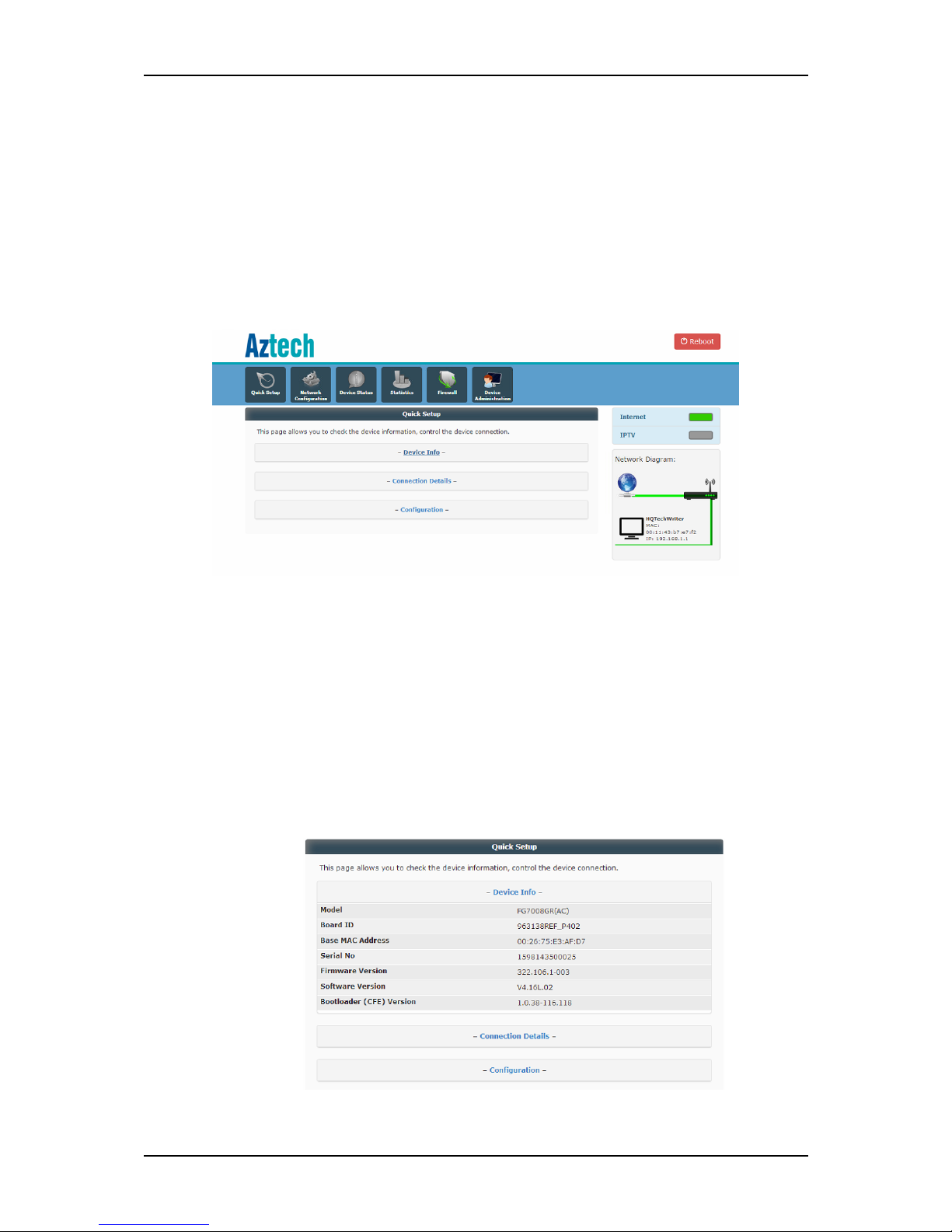
Quick Setup
The Quick Setup menu allows you to configure both the wireless properties of
your router, and the configuration of your fibre connection’s service provider.
The Quick Setup menu has the following submenus:
Quick Setup
Wireless
A. QuickSetup. The default page of the Quick Setup menu. It allows
you to view the device properties, connection details, and or
configure your FG7008GR(AC)’s service provider configuration:
Device Info. Summarizes the basic information of the
FG7008GR(AC) such as its Model, the device’s serial no., its
firmware version, and other necessary details.
Page 20
User Manual
Page 20 of 88
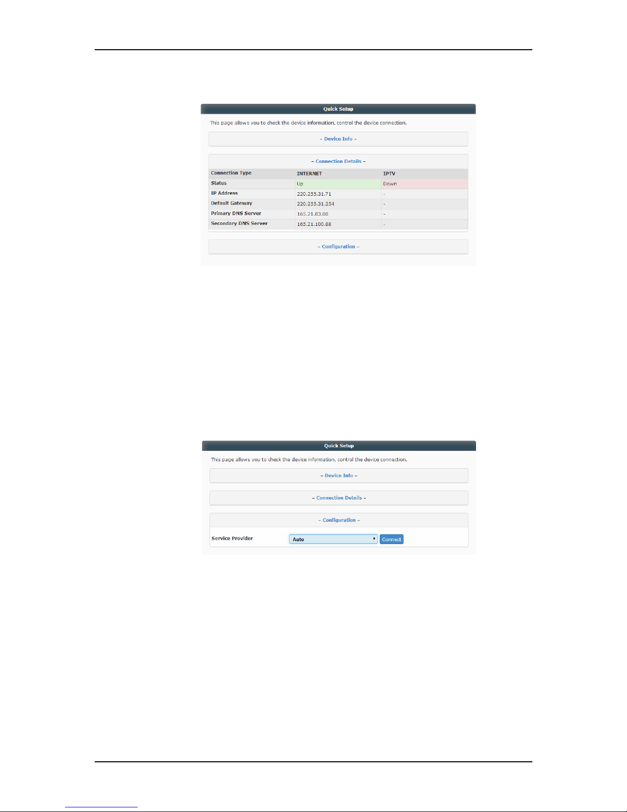
Connection Details. Displays the status of both internet and
IPTV, the IP address, and other connection oriented details.
Configuration. Allows you to configure your fibre
connectivity’s service provider.
NOTE: For Singapore Fibre Residential Customers, there is no
need to configure the Service Provider settings of your router.
The service provider is automatically detected and utilized by
your router.
Page 21
User Manual
Page 21 of 88
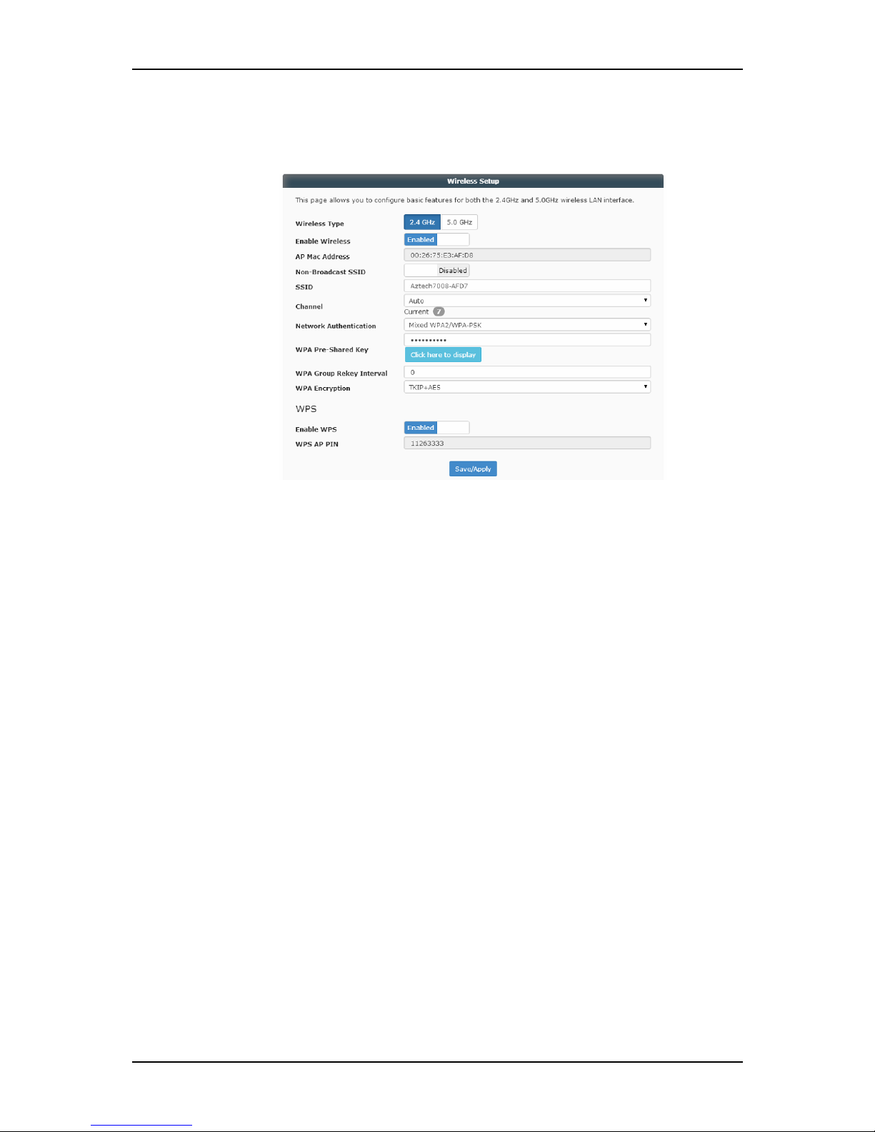
B. Wireless. Allows you to configure your router’s wireless features. The
Wireless also allows you to Enable/Disable the WPS setup and
modify the WPS AP Pin.
To configure your FG7008GR(AC)’s Wireless property:
1. Select the Wireless Type that you wish to configure (e.g.
2.4GHz or 5.0GHz).
2. If you want to hide the Network from active scans, simply tick
the Non-Broadcast-SSID checkbox.
3. You may designate an SSID or a Wireless Network Name for
your wireless network or use the default SSID of your
FG7008GR(AC).
NOTE: The Default SSID and Network key for both the 2.4GHz
and 5.0GHz band can be seen on the device label sticker of
your device.
4. Select a Channel.
NOTE: It is highly recommended to select Auto mode as your
router’s Channel setting. This enables your router to
continuously use the least congested Wi-Fi channel at all
times.
Page 22
User Manual
Page 22 of 88
5. Select a Network Authentication method on the drop down
list. It is highly suggested to use Mixed WPA2/WPA-PSK as its
authentication.
6. Enter the preferred wireless password on the Pre-Shared Key
field (if applicable).
7. Select its Encryption Type (if applicable).
8. Click the Save/Apply button to save and apply wireless
settings.
9. You may change the other band’s wireless properties as well.
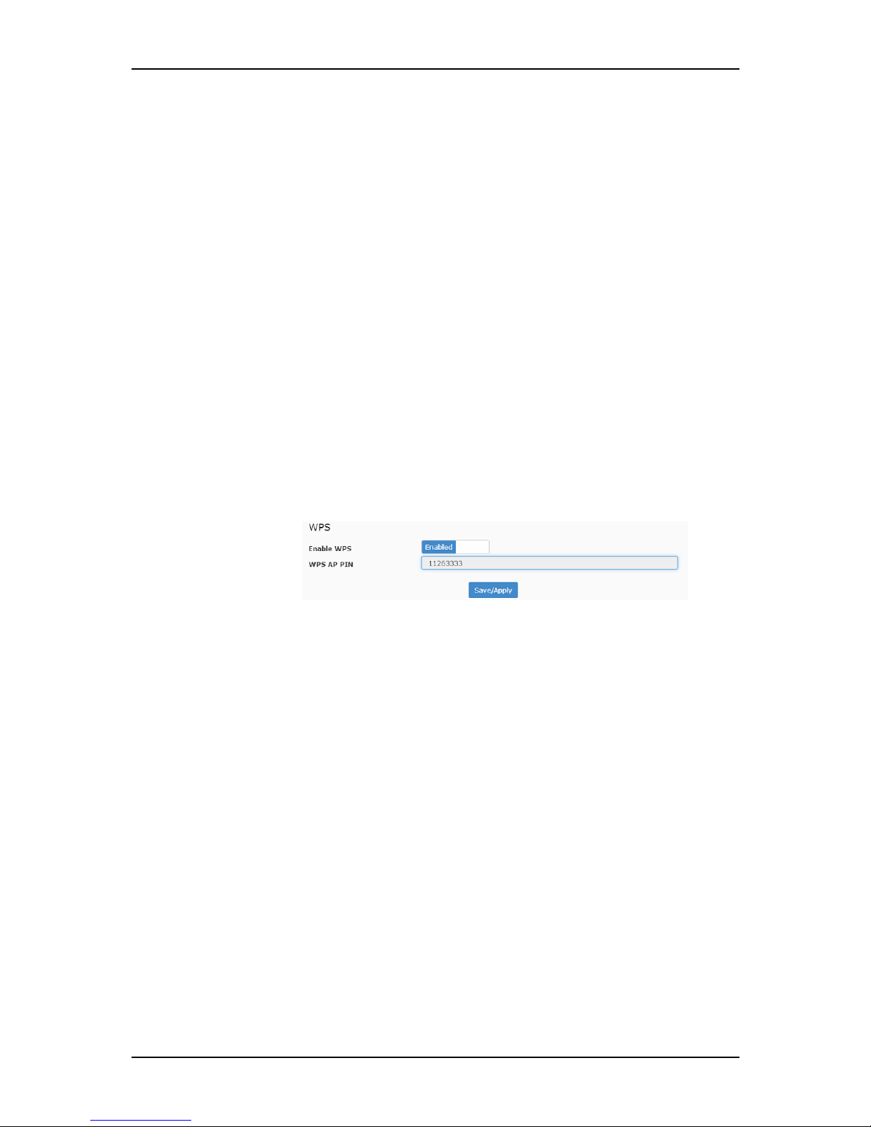
To enable or disable the WPS function:
NOTE: The WPS feature is only applicable on the 2.4GHz
frequency band.
1. On the WPS Setup section, choose whether to disable or
enable the WPS.
2. You may also copy the WPS AP Pin for future use or change it
if necessary.
NOTE: If you wish to change the WPS AP Pin, you may have to
use the Advanced Mode features of your router.
3. Click the Save/Apply button to apply changes.
Page 23
User Manual
Page 23 of 88
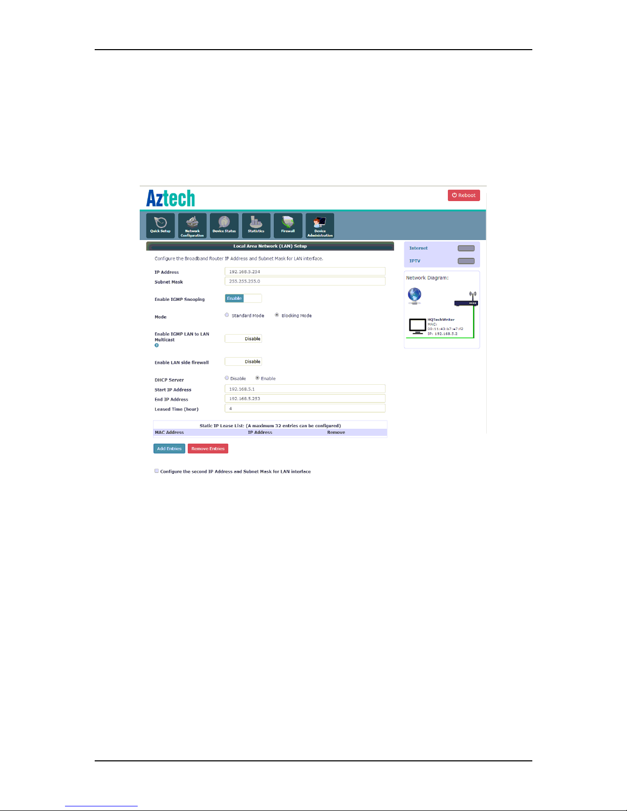
Network Configuration
The Home Network Configuration menu allows you to configure your router’s
IP Address and Subnet Mask for LAN interface. You may also configure the
DHCP server and Public IP Pass Through settings of your router through this
page. It has the following sections:
A. Local Area Network (LAN) Setup. Allows you to configure various IP
properties which will be used by your router and or implemented
throughout the network.
To configure the LAN Setup, you may follow the steps below:
1. Enter the preferred IP Address and corresponding subnet mask
that you wish to assign to your FG7008GR(AC).
NOTE: The IP Address to be specified in this area will be the new
default IP Address you would be using to access your
FG7008GR(AC) web user interface.
Page 24
User Manual
Page 24 of 88
2. You may enable or disable IGMP Snooping and its required
properties if it is required in your network. It is highly suggested
to enable this if you wish to filter out multicast traffic in your
network.
3. If you wish to enable or disable firewall filters specified in the
Firewall Configuration, tick the Enable LAN Side Firewall.
4. If you wish to implement Static IP addressing, tick Disable DHCP
Server.
NOTE: By default, DHCP Server is enabled.
5. For Dynamic IP Addressing (DHCP) tick Enable and enter the
Start IP and End IP Address, the correct subnet mask, and the
lease time (in hours) for all connected devices.
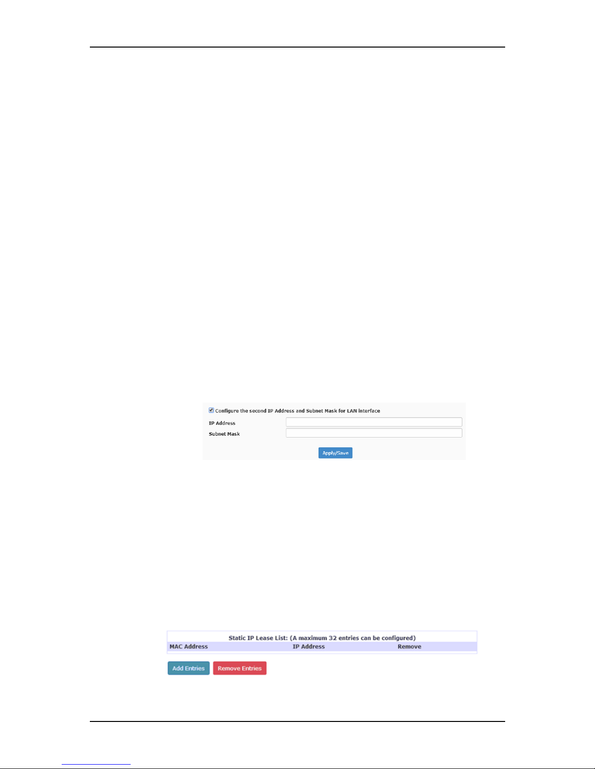
6. If you wish to indicate a second IP address for your router, tick
the Configure the second IP Address and Subnet Mask for LAN
interface and define the values needed in the fields. This may
come in handy when you are troubleshooting your router.
7. Click the Save/Reboot button to apply all changes.
Static IP Lease List. Displays the statically assigned IP addresses in
the network, each device’s MAC Address and assigned IP
Address can be seen in this table. It also allows you to remove
reserved IP addresses as well.
Page 25
User Manual
Page 25 of 88
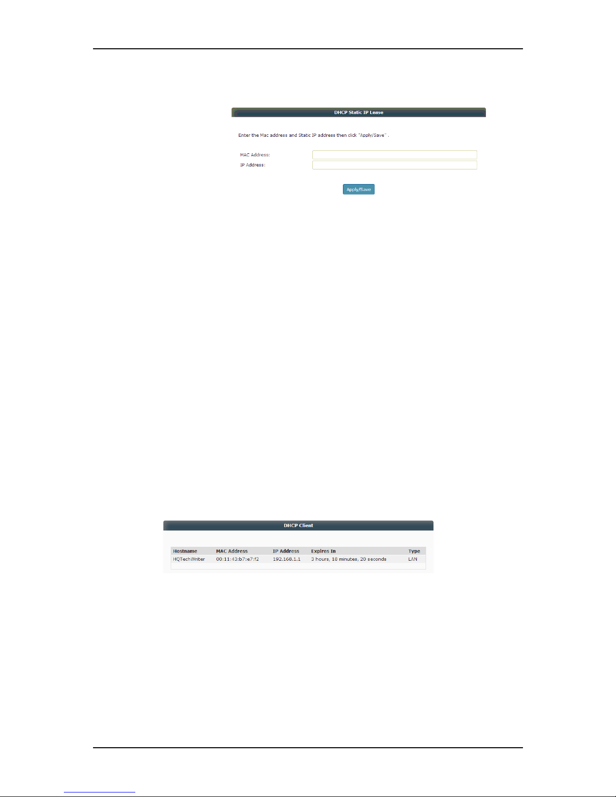
To reserve a device:
1. Click Add Entries.
2. Enter the MAC Address of the device that you wish to reserve.
3. Enter the IP Address to be assigned to the device.
4. Click Apply/Save to reserve the device.
To remove reserved devices:
1. On the Static IP Lease List table tick the Remove checkbox
that corresponds to the MAC Address of the device that you
wish to remove.
2. Click Remove to remove the device.
B. DHCP Client. Displays the dynamically assigned IP Addresses, each
devices’ corresponding hostname and MAC address, the type of
connection (WLAN or LAN), and the lease expiry time.
Page 26
User Manual
Page 26 of 88
Device Status
The Device Status page briefly displays the configurations settings and the
respective statuses of the FG7008GR(AC), its internet connection, and its IPTV
connectivity. The Device Status page has the following submenus:
System Info
Internet Status
IPTV Status
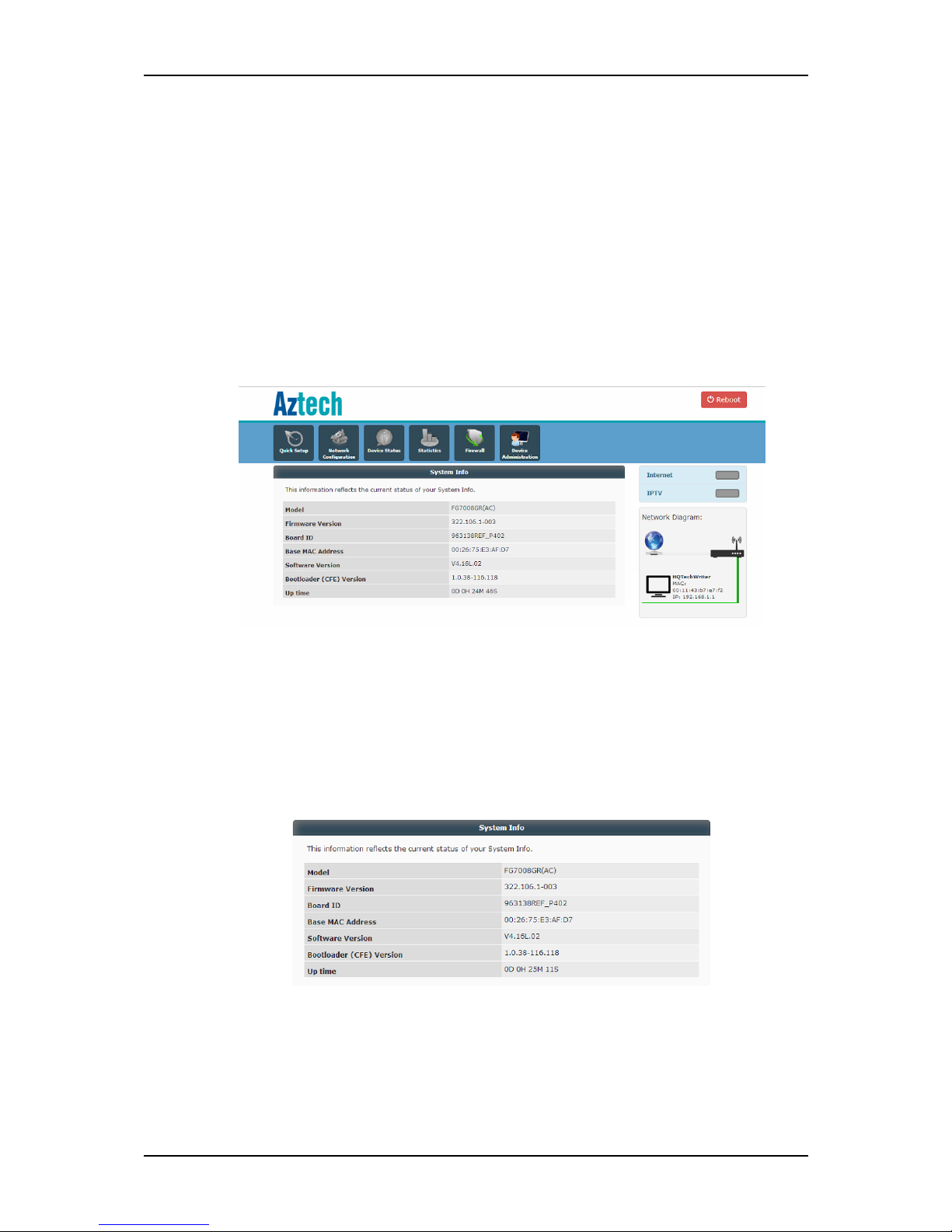
A. System Info. Displays a brief summary of your FG7008GR(AC)’s device
properties such as its model, the current firmware version loaded into
your router, the device’s unique MAC address, the system up time, and
other similar properties.
Page 27
User Manual
Page 27 of 88
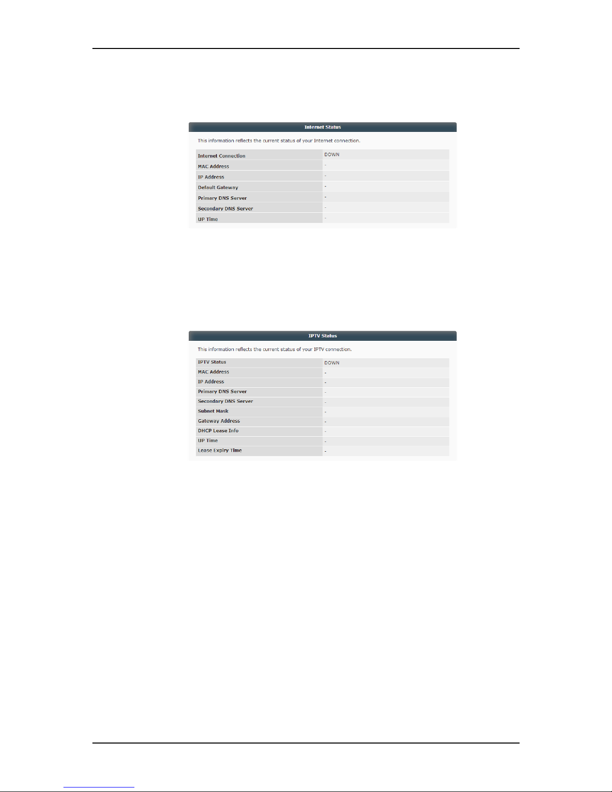
B. Internet Status. Displays the current status of the internet connection,
the default gateway, the primary and secondary DNS, and the internet
uptime.
C. IPTV Status. Displays the current status of the IPTV, its MAC and IP
Address, the default gateway, the primary and secondary DNS, and
the DHCP lease info, and its lease expiry time.
Page 28

User Manual
Page 28 of 88
Statistics
The Statistics page displays the current statistics of the different connectivity
available on your router such as Internet, IPTV, LAN, and WLAN. The Statistics
menu has the following submenus:
Internet
IPTV
LAN
WLAN
A. Internet Status. Displays the current statistics of both the received and
transmitted packets of the internet connection.
Page 29

User Manual
Page 29 of 88
B. IPTV. Displays the current statistics of both the received and transmitted
packets of the IPTV.
C. LAN. Displays the current statistics of both the received and transmitted
packets of the LAN.
D. WLAN. Displays the current statistics of both the received and
transmitted packets of both 2.4GHz and 5.0GHz frequency bands.
Page 30

User Manual
Page 30 of 88
Firewall
The Firewall menu allows you to create various filters that would be
implemented in the network, port forward or port trigger services or
applications, add and or configure DDNS account/s, and assign a DMZ Host
IP Address for your network. The Firewall Menu contains the following
submenus:
Outgoing IP Filtering
Incoming IP Filtering
Port Forwarding
Port Triggering
Dynamic DNS
DMZ
Outgoing IP Filtering. Allows you to add, configure, remove Outgoing
Filters that will Block specific data traffic to and from the Internet.
Page 31

User Manual
Page 31 of 88
To add an Outgoing IP filter:
1. Click the Add button.
2. Input the preferred Filter Name.
3. Determine the IP Version that the filter will use.
4. Select the Protocol.
5. Enter the Source’s IP Address, and Source Port.
6. Input the Destination IP Address and Destination Port.
7. Click Save/Apply button to save changes.
To remove a filter:
1. On the Filter table, tick the checkbox that corresponds to the
Filter Name that you wish to remove.
2. Click Remove to remove the filter.
Page 32

User Manual
Page 32 of 88
Incoming IP Filtering. Allows you to add, configure, remove Incoming
Filters that will Block specific data traffic to and from the Internet.
To add an Incoming IP filter:
1. Click the Add button.
2. Input the preferred Filter Name.
3. Determine the IP Version that the filter will use.
4. Select the Protocol.
5. Enter the Source’s IP Address, and Source Port.
6. Input the Destination IP Address and Destination Port.
7. Select a WAN Interface/s where the filter will apply.
8. Click Save/Apply button to save changes.
Page 33

User Manual
Page 33 of 88
To remove a filter:
1. On the Filter table, tick the checkbox that corresponds to the
Filter Name that you wish to remove.
2. Click Remove to remove the filter.
Port Forwarding. Allows you to configure your router to forward
incoming and outgoing data transmissions of applications that require
accessing a specific port for communication over the network or
Internet. A maximum of 32 entries can be configured.
To port forward a service:
1. Click the Add button.
Page 34

User Manual
Page 34 of 88
2. Determine the interface that would be used.
3. You can select an service on the Select a Service drop down list (if
the application needed is present).
4. If the application needed is not present on the dropdown list, you
may have to select Custom Server. Enter the preferred application
name on the Custom Server field.
5. Enter the External Port Start and External Port End values and
determine the Protocol to be implemented.
NOTE: The External Port Start/End field would immediately be used
as the Internal Port Start/End field. You may also have to search for
your application’s corresponding port ranges.
6. Click Save/Apply button to apply changes.
To remove a port forwarded service:
1. Tick the checkbox of the corresponding service that you wish to
remove.
2. Click Remove to remove the port forwarded service.
Page 35

User Manual
Page 35 of 88
Port Triggering. Some applications require that the remote parties open
the specific ports in the router’s firewall for access. For instance, an
application uses port 25 for requests and port 113 for replies. If a
computer on the LAN connects to port 25 on a remote server hosting
this application, using Port Triggering on the router, incoming
connections to port 113 (from the remote server) could be redirected
to the PC that initiated the request. A maximum of 32 entries can be
configured.
To add a port trigger:
1. Click the Add button.
Page 36

User Manual
Page 36 of 88
2. Determine the interface that would be used.
3. You can select an application on the Application drop down list (if
the application needed is present).
4. If the application needed is not present on the dropdown list, you
may have to select Custom Application and enter the preferred
application name on the Custom Application field.
5. Enter the Trigger Port Start and Trigger Port End values and
determine the Trigger Protocol to be implemented.
NOTE: You may have to search for your application’s corresponding
port ranges.
6. Enter the Open Port Start and Open Port End values and determine
the Open Protocol to be implemented.
NOTE: You may have to search for your application’s corresponding
port ranges.
7. Click Save/Apply button to apply changes.
To remove a port trigger:
1. Tick the checkbox of the corresponding application that you wish to
remove.
2. Click Remove to remove the port triggered application.
Page 37

User Manual
Page 37 of 88
Dynamic DNS. The router offers a Dynamic Domain Name System
(DDNS) feature. DDNS lets you assign a fixed host and domain name to
a dynamic Internet IP Address. It is useful when you are hosting your
own website, FTP server, or other servers behind the router.
Before using this feature, you need to sign up for DDNS service
providers. The router supports these popular Dynamic DNS service
providers:
www.dyndns.org
www.tzo.com
To add a DDNS account:
1. Click the Add button.
2. Select your D-DNS provider.
3. Enter the preferred Hostname.
4. Select the Interface.
5. Enter your D-DNS account’s Username and password.
6. Click the Add button.
Page 38

User Manual
Page 38 of 88
To remove a DDNS setting:
1. Tick the Remove box that corresponds to the DDNS Hostname
that you wish to remove.
2. Click the Remove button.
DMZ Host. Allows you to assign a computer as a DMZ Host. It will then
receive all the data from the Internet that does not belong to the list of
applications configured in Port Forwarding.
To configure the DMZ host:
1. Enter the LAN IP address of the PC you wish to set as DMZ Host in
the DMZ Host IP Address.
2. Click the Save/Apply button to apply changes.
3. If you need to disable the DMZ Host, simply clear the IP Address
field and click the Save/Apply button.
Page 39

User Manual
Page 39 of 88
Device Administration
The Device Administration menu allows you to backup the current
configurations set on your router, perform factory reset, load the previously
saved backup configuration files, perform firmware upgrade, change the
Web User Interface password, and perform factory reboot.
NOTE: Upon clicking the Device Administration menu icon, you would be
prompted to enter a username and password. Simply enter admin as its
username and password. It has the following submenus:
Backup Settings
Restore Default
Update Settings
Firmware Upgrade
Reboot
User Password
A. Backup Settings. Allows you to save the router’s configuration as a file
on your PC.
To back up your router’s configuration:
1. Click on the Backup Settings button.
2. Select the file folder on your PC where you want the backup file to
be saved.
B. Restore Default. Resets the entire router configuration back to its
original default factory settings by simply clicking on the Restore Default
Settings button.
Page 40

User Manual
Page 40 of 88
C. Update Settings. Allows you to update the router settings from a
previously stored backup file on a computer.
To update the router settings:
1. Click on the Choose File button.
2. Locate the backupsettings.conf file from your computer.
3. Click Open.
4. Click on the Update Settings button. The router will update the
settings according to the backupsettings.conf file and reboot.
D. Firmware Upgrade. Allows you to update the current firmware
available on your router.
NOTE: It is STRICTLY recommended to use OFFICIAL Aztech Firmware
only. These can be downloaded on the Aztech Support Website
(www.aztech.com/support).
To upgrade the router’s firmware simply do the following steps:
1. Click on the Choose File button and locate the downloaded
firmware file.
2. Choose the firmware file and click OK.
3. Click the Update Firmware button.
Page 41

User Manual
Page 41 of 88
E. Reboot. Saves recent changes made on the router and reboots the
whole system for the new settings to take effect. Simply click the
Reboot button to reboot your router.
F. User Password. Allows you to change the current password set on each
user account.
Page 42

User Manual
Page 42 of 88
Advanced Mode
Advanced Mode provides more configuration options for other router
functions available in your FG7008GR(AC).
To access the Advanced Web Interface:
1. Launch a Web browser (e.g. Internet Explorer, Google Chrome).
2. Type-in 192.168.1.254/admin on the address bar and then press Enter.
An Authentication Window will appear.
3. Key in the default username and password:
Username : admin
Password : admin
4. Click Login to enter the Advanced Mode.
Menus
The Advanced Mode Web User Interface includes the following menus:
Device Info
Device Statistics
Advanced Setup
Security
Wireless
Diagnostics
Management
Page 43

User Manual
Page 43 of 88
Device Info
Displays a brief summary of the hardware, software, WAN, the wired and
wirelessly connected DHCP Clients, the ARP table, and the routing
information of your router. The Device Info page has the following submenus:
Device Info Summary
WAN Info
Route
ARP
DHCP Client
A. Device Info Summary. Displays the both basic properties of your
FG7008GR(AC)’s system and WAN connection. Information such as its
firmware and software version, the bootloader version, the wireless
driver version, system uptime, and useful WAN information settings can
be seen in this area.
Page 44

User Manual
Page 44 of 88
B. WAN Info. Displays the current configuration settings on each ethernet
interface.
C. Route. Displays the properties of the destination IP addresses you have
defined such as its subnet mask, metric, status or flag, and its interface.
D. ARP. Displays the IP Addresses and the MAC addresses of all the
devices directly connected (through Ethernet port) to the
FG7008GR(AC).
E. DHCP Client. Displays the hostname, MAC and IP address, the lease
expiry time, and the connection type (LAN, WLAN – 2.4GHz or 5.0GHz)
of all devices that has been dynamically assigned with an IP address.
Page 45

User Manual
Page 45 of 88
Statistics
The Statistics page displays detailed statistical transmit and receive
information regarding the LAN and WAN connection of your router. It has the
following submenus.
LAN
WAN
A. LAN. Displays detailed information regarding the packets received and
transmitted throughout each interface such as the total number of
bytes for multicast, and the total number of packets for
multicast/unicast/broadcast.
Page 46

User Manual
Page 46 of 88
B. WAN. Displays detailed information regarding the packets received
and transmitted throughout each ethernet interface such as the total
number of bytes for multicast, and the total number of packets for
multicast/unicast/broadcast.
Page 47

User Manual
Page 47 of 88
Advanced Setup
Allows you to configure the ATM and PTM Settings, add WAN Interfaces,
configure the DDNS settings, and other advanced properties. It has the
following submenus:
Layer2 Interface
WAN
LAN
IPv6 Autoconfig
NAT
Quality of Service
Routing
DNS
UPnP
DNS Proxy
Print Server
Storage Service
Interface Grouping
IP Tunnel
Certificate
Power Management
Multicast
Precedence
A. Layer2 Interface. Shows existing ETH WAN interfaces configured on your
router. You have an option to Remove these configurations.
NOTE: At least one Ethernet is needed for the layer 2 WAN interface.
Page 48

User Manual
Page 48 of 88
To remove an Eth WAN interface:
1. Tick the check box of the corresponding interface/s that you
wish to remove.
2. Click the Remove button to remove the selected interface/s.
B. WAN. Shows existing WAN interfaces configured on your router. You
have an option to Remove, and Edit WAN interface configurations.
These WAN interfaces may be found useful in Port Triggering, Port
Forwarding, and in other features available in your router.
To add a WAN Interface:
1. Click the Add button.
2. Select an Interface then click Next.
3. Select a WAN Service Type, determine its Service Description,
identify 802.1P Priority and 802.1Q VLAN ID, select a VLAN TPID
and its Network Protocol then click Next.
Page 49

User Manual
Page 49 of 88
4. Enter the PPP Account details as provided by your ISP. You may
also opt to enable Fullcone NAT, dial on demand, PPP IP
extension, PPP debug mode, Bridge PPPoE frames, IGMP
Multicast Proxy, and identify a static IPv4 address. Click Next to
proceed.
Page 50

User Manual
Page 50 of 88
5. Specify at least one interface for the Default Gateway Interfaces
column, assign preferred interfaces on the Available Router WAN
Interfaces, then click Next.
6. Identify if you would be using the DNS Server Interface from
available WAN interfaces, or if you would be using your preferred
Static DNS IP address. Please configure the needed attributes of
the selected property then click next.
7. On the WAN Setup – Summary, determine if the settings identified
matches the entered configuration. If settings are correct, click
the Apply/Save button to finalize settings.
Page 51

User Manual
Page 51 of 88
C. IPv6 LAN Auto Configuration. Allows you to specify a static LAN IPv6
address and its prefix length, enable/disable the IPV6 properties of your
router such as DHCPv6 Server, RADVD, and MLD Snooping. Do take
note that you have to enable the property first before you can enter or
configure the parameters for the said properties
D. IPv6 LAN Auto Configuration. Allows you to specify a static LAN IPv6
address and its prefix length, enable/disable the IPV6 properties of your
router such as DHCPv6 Server, RADVD, and MLD Snooping. Do take
note that you have to enable the property first before you can enter or
configure the parameters for the said properties.
Page 52

User Manual
Page 52 of 88
E. NAT. Allows you to configure the Port Forwarding, Port Triggering, and
DMZ settings of your router. It has the following submenus:
Port Forwarding. Port Forwarding allows you to direct incoming
traffic from the Internet to a specific computer in your local
network. A maximum of 32 entries can be configured.
To port forward a service:
a. Click the Add button.
b. Determine the interface that would be used.
c. You can select an service on the Select a Service drop
down list (if the application needed is present).
Page 53

User Manual
Page 53 of 88
d. If the application needed is not present on the dropdown
list, you may have to select Custom Server. Enter the
preferred application name on the Custom Server field.
e. Enter the External Port Start and External Port End values
and determine the Protocol to be implemented.
NOTE: The External Port Start/End field would immediately
be used as the Internal Port Start/End field. You may also
have to search for your application’s corresponding port
ranges.
f. Click Save/Apply button to apply changes.
To remove a port forwarded service:
a. Tick the checkbox of the corresponding service that you
wish to remove.
b. Click Remove to remove the port forwarded service.
Port Triggering. Some applications require that the remote parties
open the specific ports in the router’s firewall for access. For
instance, an application uses port 25 for requests and port 113 for
replies. If a computer on the LAN connects to port 25 on a
remote server hosting this application, using Port Triggering on
the router, incoming connections to port 113 (from the remote
server) could be redirected to the PC that initiated the request. A
maximum of 32 entries can be configured.
Page 54

User Manual
Page 54 of 88
To add a port trigger:
a. Click the Add button.
b. Determine the interface that would be used.
c. You can select an application on the Application drop
down list (if the application needed is present).
d. If the application needed is not present on the dropdown
list, you may have to select Custom Application. Enter the
preferred application name on the Custom Application
field.
e. Enter the Trigger Port Start and Trigger Port End values and
determine the Trigger Protocol to be implemented.
Page 55

User Manual
Page 55 of 88
NOTE: You may have to search for your application’s
corresponding port ranges.
f. Enter the Open Port Start and Open Port End values and
determine the Open Protocol to be implemented.
NOTE: You may have to search for your application’s
corresponding port ranges.
g. Click Save/Apply button to apply changes.
To remove a port trigger:
a. Tick the corresponding checkbox of the application.
b. Click Remove to remove the port triggered application.
DMZ Host. Allows you to assign a computer as a DMZ Host. It will
then receive all the data from the Internet that does not belong
to the list of applications configured in Port Forwarding.
To configure the DMZ host:
a. Enter the LAN IP address of the PC you wish to set as DMZ
Host in the DMZ Host IP Address.
b. Click the Save/Apply button to apply changes.
Page 56

User Manual
Page 56 of 88
c. If you need to disable the DMZ Host, simply clear the IP
Address field and click the Save/Apply button.
F. Quality of Service. Quality of Service or QoS provides different priorities
to different applications, users, or data flows, to guarantee a certain
level of performance. It has the following submenus:
QoS – Queue Setup. Allows you to queue services in each
Ethernet Interface. A maximum of four (4) queues can be
configured in each interface.
QoS Classification Setup. Allows you to view and customize the
rules or policies which would be implemented in QoS queues.
To add a Network Traffic Class Rule:
a. Click the Add button.
Page 57

User Manual
Page 57 of 88
b. Enter the preferred Traffic Class Name.
c. Enter the Rule Order priority and identify its Rule Status.
d. Determine its Class Interface, its Ether Type, and determine
the Source/Destination MAC Address/MAC.
e. Identify the Class Queue.
f. Determine the DSCP, 802.1p priority, and Rate Limit value.
g. Click the Apply/Save button to proceed.
Page 58

User Manual
Page 58 of 88
G. Dynamic DNS. Allows you to configure the DNS Server settings, and
add/configure/remove DDNS accounts. It has the following submenus:
DNS Server. Allows you to select a DNS server interface/s from
available WAN interfaces and prioritize selected interfaces
according to the order specified, or use a static DNS IP address
for your DNS, and other similar settings.
Dynamic DNS. The router offers a Dynamic Domain Name System
(DDNS) feature. DDNS lets you assign a fixed host and domain
name to a dynamic Internet IP Address. It is useful when you are
hosting your own website, FTP server, or other servers behind the
router.
Before using this feature, you need to sign up for DDNS service
providers. The router supports these popular Dynamic DNS
service providers:
www.dyndns.org
www.tzo.com
Page 59

User Manual
Page 59 of 88
To add a DDNS account:
1. Click the Add button.
2. Select your D-DNS provider.
3. Enter the preferred Hostname.
4. Select the Interface.
5. Enter your D-DNS account’s Username and password.
6. Click the Add button.
To remove a DDNS setting:
1. Tick the Remove box that corresponds to the DDNS Hostname
that you wish to remove.
2. Click the Remove button.
Page 60

User Manual
Page 60 of 88
H. UPnP. Allows you to enable the Universal Plug and Play feature of your
FG7008GR(AC). The UPnP feature allows an easier means of device
discovery in your network (e.g. network printer etc.).
I. DNS Proxy. Allows you to enable and configure the DNS proxy features
of your FG7008GR(AC) such as the Broadband router’s preferred
hostname, and the domain name of the LAN network that you wish to
assign.
J. Print Server. Allows you to enable the Print Server features of the
FG7008GR(AC).
To use the print server, you need to accomplish the following tasks:
NOTE: To change printer server settings, you must first tick the
checkbox Enable on-board print server.
1. Install the printer drivers on the computer.
2. Enable the FG7008GR(AC) for Print Server.
3. Add a network printer.
Page 61

User Manual
Page 61 of 88
Install the Printer Driver
Printers using the USB port come with a software installation CD for
installing printer drivers and applications. The drivers for the printers
must be installed on the computer first to prepare it for use after
connecting it to your FG7008GR(AC). Refer to the printer’s
documentation on how to install the drivers.
To Enable the Print Server Application
1. Open you Internet browser and go to Advanced Mode.
2. Click on Advanced Setup then go to Print Server.
3. Click Enable on-board print server.
4. Input the Printer Name and Printer Make and Model on the fields.
5. To commit and save the changes, click on Save/Apply button.
Connecting the Printer
1. Turn OFF the FG7008GR(AC).
2. Connect the Printer on the USB port and switch it ON.
To Add a Network Printer
For Windows 7
1. Click on the Start Button> Control Panel.
Page 62

User Manual
Page 62 of 88
2. On Devices and Printers Category, Click on the Add a Printer link.
3. On the Add printer window, click on the Add a network, wireless
or Bluetooth printer button.
4. Your computer would automatically search for connected
printers. Click on Stop on Searching for available printers… page.
5. Click on The printer that I want isn’t listed button.
Page 63

User Manual
Page 63 of 88
6. Click on Select a shared printer by name on the Find a printer by
name on TCP/IP address, and input the following URL on the field
and click on Next.
This is the printer name that you've set earlier
http://192.168.1.254:631/printers/PrinterBrotxx
7. Once the computer detects the printer on the Print Server, it will
ask for the printer manufacturer and model; a list of printers will
be shown. Select your printer from the list and click OK.
Page 64

User Manual
Page 64 of 88
8. Click Next on the Type a Printer Name window.
9. To print a test page click on Print a test page button on the
confirmation screen, and click Finish to complete the installation.
Notes:
1. USB Printers that supports IPP – Internet Printing Protocol are
the only printers that will work with the Print Server
application on the FG7008GR(AC). Consult the printer
manufacturer for more information about your printer.
2. Scanning, Faxing and Photocopying functions on
Multifunction printers are currently not supported on the
FG7008GR(AC). Print function however is the only feature
Page 65

User Manual
Page 65 of 88
that will work on these printer types when connected to
the FG7008GR(AC) router.
3. Refrain from connecting a USB Hub on the USB port of the
FG7008GR(AC).
K. Storage Service. Allows you to view a brief summary of the directly
connected storage devices in your FG7008GR(AC). It has the following
submenus
Storage Device Info. Displays a summary of the directly
connected storage devices in the FG7008GR(AC). Info such as
the volume name, the file system, and the total and used space
can be seen in this area.
User Accounts. Allows you to define a username and password
for the storage device/s connected to your FG7008GR(AC).
L. Interface Grouping. Allows you to group multiple LAN interfaces into
one single group, wherein each group would be working as an
independent network.
NOTE: By default, all interfaces belong to the Default group.
Page 66

User Manual
Page 66 of 88
To add an interface group:
a. Click the Add button.
b. Enter your preferred Group Name.
c. Define the LAN Interfaces from the Available LAN interfaces
list that will be added to the group.
d. Determine the DHCP Vendor IDs which would define other
clients that you would like to be added to the group.
e. Click Apply/Save to apply the preferred changes.
f. Reboot the router for the settings to take place.
Page 67

User Manual
Page 67 of 88
M. IP Tunnel. Allows you to configure the IP tunneling properties of both
IPv6 and IPv4. It has the following submenus:
IPv6inIPv4.
IPv4inIPv6.
N. Certificate. Allows you to view, remove, add, and import, both local
and trusted certificates.
Local Certificates. Allows you to view, create, and import local
certificates. These certificates are used by peers to verify your
identity.
Trusted CA. Allows you to view, add, or remove certificates
trusted certificates. These certificates are used by your router to
verify peers’ certificates.
O. Power Management. Allows you to control hardware modules for
effective power consumption. It is best to enable all power
management features for the best power efficient performance.
Page 68

User Manual
Page 68 of 88
P. Multicast Precedence. Allows you to enable the Multicast Precedence
property of your router, and configure the default IGMP and MLD (for
IPv6) protocol settings set on your router.
Page 69

User Manual
Page 69 of 88
Security
The Security menu allows you to create various filters that would be
implemented in the network such as incoming and outgoing IP filters, access
time restriction, and URL filtering. It has the following submenus:
Outgoing IP Filtering
Incoming IP Filtering
Access Time Restriction
URL Filtering
A. Outgoing IP Filtering. Allows you to add, configure, remove Outgoing
Filters that will Block specific data traffic to and from the Internet.
Page 70

User Manual
Page 70 of 88
To add an Outgoing IP filter:
1. Click the Add button.
2. Input the preferred Filter Name.
3. Determine the IP Version that the filter will use.
4. Select the Protocol.
5. Enter the Source’s IP Address, and Source Port.
6. Input the Destination IP Address and Destination Port.
7. Click Save/Apply button to save changes.
To remove a filter:
1. On the Filter table, tick the checkbox that corresponds to the
Filter Name that you wish to remove.
2. Click Remove to remove the filter.
Page 71

User Manual
Page 71 of 88
B. Incoming IP Filtering. Allows you to add, configure, remove Incoming
Filters that will Block specific data traffic to and from the Internet.
To add an Incoming IP filter:
1. Click the Add button.
2. Input the preferred Filter Name.
3. Determine the IP Version that the filter will use.
4. Select the Protocol.
5. Enter the Source’s IP Address, and Source Port.
6. Input the Destination IP Address and Destination Port.
7. Select a WAN Interface/s where the filter will apply.
8. Click Save/Apply button to save changes.
Page 72

User Manual
Page 72 of 88
To remove a filter:
1. On the Filter table, tick the checkbox that corresponds to the
Filter Name that you wish to remove.
2. Click Remove to remove the filter.
C. Access Time Restriction. Allows you to add daily time restrictions to
specific device/s currently connected to the Router (wirelessly or
wired).
To add an access time restriction:
1. Click the Add button.
2. Enter the Username where the adding of restriction rule would be
registered to. This could be any Username that will help identify who
added the specific restriction.
3. Determine the device where the time restriction would apply. This
could either be your own IP address, or other MAC addresses. All
connected devices’ (wired or wireless) MAC Address would be seen
in this drop down list. If the device’s MAC Address is not present, you
Page 73

User Manual
Page 73 of 88
may have to identify the device’s MAC address on the Other MAC
Address Field.
To know your device’s MAC Address :
a. Open the Command Prompt.
b. Type in ipconfig/all and locate the MAC Address label
generated on the screen.
4. Tick the checkboxes of the Days of the Week where you wish to
apply the restriction.
5. Identify the Start and End Blocking time that would apply for each
day.
6. NOTE: The Start and End Blocking time fields only supports a 24-Hour
Format, and requires a colon (:) to separate the hours from minutes.
7. Click Apply to finalize the restriction.
D. URL Filter. Allows you to exclude or include URL filters that would be
accessible/inaccessible throughout the network.
E. URL Filter. Allows you to exclude or include URL filters that would be
accessible/inaccessible throughout the network.
To add a URL Filter:
1. Select a URL List type.
2. Click the Add button.
Page 74

User Manual
Page 74 of 88
3. Enter the URL Address that you wish to filter.
4. Enter the Port Number (by default this is set as 80).
5. Click the Apply/Save button to save and apply the changes.
Page 75

User Manual
Page 75 of 88
Wireless
The Wireless menu in advanced mode allows you to fully configure the overall
features provided by the 2.4GHz and the 5.0GHz wireless frequency bands. It
has the following submenus:
A. 2.4GHz. Allows you to configure the overall properties of the 2.4GHz
wireless frequency band. It has the following submenus:
Basic
Security
Wireless Bridge
Advanced
Station Info
Page 76

User Manual
Page 76 of 88
Basic. Allows you to configure the basic features of the wireless
LAN interface such as the enabling/disabling of the wireless
interface and multicast forwarding, changing of wireless SSID
Security. Allows you to configure the security features of the
wireless LAN interface’s different SSIDs, and its WPS properties.
Page 77

User Manual
Page 77 of 88
Bridge. Allows you to configure the wireless bridge features of the
wireless LAN interface.
Enabled. Enables wireless bridge restriction, with bridges
selected in Remote Bridges having access.
Disabled. Disables bridge restriction. All wireless bridges will be
granted access.
To configure the wireless bridge:
1. Select the Bridge Restriction.
2. Input the Remote Bridges MAC Addresses.
3. Click Apply/Save to save and apply changes.
Advanced. Allows you to configure the Advanced features of
the wireless LAN interface. You can select a particular channel
on which to operate for the transmission to consistently stay on a
particular speed, set preferred fragmentation/RTS threshold,
identify wakeup intervals for clients in power save mode,
determine a beacon interval for the access point, and other
advanced wireless properties.
Page 78

User Manual
Page 78 of 88
Authenticated Stations. Provides a brief table of all the wirelessly
connected devices to the 2.4GHz band, each devices’ MAC
address, the SSID where it is currently connected to, and the
interface it is currently using.
Page 79

User Manual
Page 79 of 88
B. 5.0GHz. Allows you to configure the overall properties of the 5.0GHz
wireless frequency band. It has the following submenus:
Basic. Allows you to configure the basic features of the wireless
LAN interface such as the enabling/disabling of the wireless
interface, hiding the wireless network from active scans, setting
or changing thr wireless network name, and other similar
activities.
Advanced. Allows you to configure the Advanced features of
the 5.0GHz wireless LAN interface. You can select a particular
channel on which to operate, identify the DTIM interval, and
determine a beacon interval for the 5.0GHz frequency band.
Authenticated Stations. Provides a brief table of all the wirelessly
connected devices to the 5.0GHz band, each devices’ MAC
address, the SSID where it is currently connected to, and the
interface it currently using.
Page 80

User Manual
Page 80 of 88
Diagnostics
The Diagnostics menu allows you to perform diagnostic tests on all the ports
of your FG7008GR(AC) including its wireless connection. It has the following
submenus:
A. Diagnostics. Displays the status of all ports (Ethernet, WAN, and USB),
including the status of your wireless connectivity.
B. Ethernet Link OAM. Allows you to enable/disable Ethernet service OAM
(802.1ag / Y.1731), and loop back and link trace tests which will allow
you to check the overall status and performance of all Ethernet ports.
Page 81

User Manual
Page 81 of 88
Management
The Management menu page allows you to perform configuration backup,
settings update, and default restore. It also allows you to view the system and
security logs, change the internet time, configure the access controls,
change the passwords currently set in your router, perform firmware
upgrades, and device rebooting. It has the following submenus:
Settings
System Log
Security Log
Internet Time
Access Control
Passwords
Firmware Upgrade
Reboot
A. Settings. Allows you to do configuration backup, settings update, and
reset the device to its factory default settings. It has the following
submenus:
Backup. Allows you to backup the current configuration settings
of your router to a backupsettings.conf file which you can use in
updating the setting of your router.
To backup the settings as a configuration file saved on your PC:
a. Click the Backup button.
Page 82

User Manual
Page 82 of 88
b. Select the folder where you want to save the file and key in
the file name under which you want to save the settings.
NOTE: The default file name is backupsettings.conf.
Update. Allows you to revert to the previous configurations of your
router that you have backed up. Please take note that you need
to have a backup file first before you can Update the settings.
To import a previously saved configuration file from your PC and
update the settings of your router:
a. Click Choose File then locate the backupsettings.conf
upgrade file.
b. Click the Update Settings button.
Restore Default. Allows you to restore or revert your router’s
current settings to its factory defaults.
To restore your router to its factory default settings:
a. Click the Restore button.
b. When prompted, click OK.
Page 83

User Manual
Page 83 of 88
B. System Log. Allows you to view and configure the System Logs of your
router. This can be useful when you want to keep track of the current
activities or changes made by and in your router.
C. Security Log. Allows you to view the security log and configure the
security log options.
D. Internet Time. Allows you to automatically synchronize the router’s time
configuration to preferred NTP time servers, and set time zone offset that
the router will use.
E. Access Control. Allows you to enable or disable services from being
used on the WAN interface.
Page 84

User Manual
Page 84 of 88
F. Passwords. Allows you to change the current password implemented in
each User Account level. By default, the only accessible Account Levels
are Admin and Support, both of which would be using the password:
Admin.
The user name Admin has unrestricted access of all the features
available in your router.
The user name Support is used to allow an ISP technician to
access your DSL Router for maintenance and to run diagnostics.
Old Password : admin
The username User can access the DSL Router, view
configuration settings and statistics, as well as, update the
router's software.
Old Password : None (Leave it Blank)
The username Guest is only capable of viewing the Basic mode
of the Web User Interface.
Old Password : None (Leave it Blank)
Note: Password cannot contain space (e.g. Password
123, admin 123).
Page 85

User Manual
Page 85 of 88
G. Firmware Upgrade. Allows you to update the firmware of your router. It is
highly recommended to ONLY UPDATE your router using OFFICIALLY
RELEASED Aztech firmware downloadable from our Aztech Support Site
(www.aztech.com/support).
H. Reboot. This feature allows your router to enable new network
configurations to take effect or to clear problems with the router’s
network connection.
Page 86

User Manual
Page 86 of 88
Safety Precautions
Do not open, service, or change any component.
Only qualified technical specialists are allowed to service the
equipment.
Observe safety precautions to avoid electric shock
Check voltage before connecting to the power supply. Connecting to
the wrong voltage will damage the equipment.
Page 87

User Manual
Page 87 of 88
Page 88

User Manual
Page 88 of 88
Copyright © 2014 Aztech Technologies Pte Ltd ( CRN:199800635M ). All rights reserved.
 Loading...