

Page 1

DSL8800GR(S)
WIRELESS-N DUAL BAND
CONCURRENT GIGABIT ROUTER
WITH BUILT-IN ADSL2+ MODEM
V1.0
Page 2

User Manual
Page 2 of 52
© Copyright 2013 All rights reserved.
No part of this document may be reproduced, republished, or retransmitted in any form or
by any means whatsoever, whether electronically or mechanically, including, but not limited
to, by way of photocopying, recording, information recording, or through retrieval systems
without the express written permission. We reserve the right to revise this document at any
time without the obligation to notify any person and/or entity. All other company or product
names mentioned are used for identification purposes only and may be trademarks of their
respective owners.
LIMITATION OF LIABILITY AND DAMAGES
THE PRODUCT AND THE SOFTWARES WITHIN ARE PROVIDED "AS IS," BASIS. THE MANUFACTURER
AND MANUFACTURER’S RESELLERS (COLLECTIVELY REFERRED TO AS “THE SELLERS”) DISCLAIM
ALL WARRANTIES, EXPRESS, IMPLIED OR STATUTORY, INCLUDING WITHOUT LIMITATION THE
IMPLIED WARRANTIES OF NON-INFRINGEMENT, MERCHANTABILITY OR FITNESS FOR A
PARTICULAR PURPOSE, OR ANY WARRANTIES ARISING FROM COURSE OF DEALING, COURSE
OF PERFORMANCE, OR USAGE OF TRADE. IN NO EVENT WILL THE SELLERS BE LIABLE FOR
DAMAGES OR LOSS, INCLUDING BUT NOT LIMITED TO DIRECT, INDIRECT, SPECIAL WILLFUL,
PUNITIVE, INCIDENTAL, EXEMPLARY, OR CONSEQUENTIAL, DAMAGES, DAMAGES FOR LOSS OF
BUSINESS PROFITS, OR DAMAGES FOR LOSS OF BUSINESS OF ANY CUSTOMER OR ANY THIRD
PARTY ARISING OUT OF THE USE OR THE INABILITY TO USE THE PRODUCT OR THE SOFTWARES,
INCLUDING BUT NOT LIMITED TO THOSE RESULTING FROM DEFECTS IN THE PRODUCT OR
SOFTWARE OR DOCUMENTATION, OR LOSS OR INACCURACY OF DATA OF ANY KIND,
WHETHER BASED ON CONTRACT, TORT OR ANY OTHER LEGAL THEORY, EVEN IF THE PARTIES
HAVE BEEN ADVISED OF THE POSSIBILITY OF SUCH DAMAGES. THE ENTIRE RISK AS TO THE
RESULTS AND PERFORMANCE OF THE PRODUCT OR ITS SOFTWARE IS ASSUMED BY CUSTOMER.
BECAUSE SOME STATES DO NOT ALLOW THE EXCLUSION OR LIMITATION OF LIABLITY FOR
DAMAGES, THE ABOVE LIMITATION MAY NOT APPLY TO THE PARTIES. IN NO EVENT WILL THE
SELLERS’ TOTAL CUMULATIVE LIABILITY OF EACH AND EVERY KIND IN RELATION TO THE
PRODUCT OR ITS SOFTWARE EXCEED THE AMOUNT PAID BY CUSTOMER FOR THE PRODUCT.
Page 3

User Manual
Page 3 of 52
Contents
About the Router ......................................................................................................... 4
Requirements ................................................................................................ 5
Package Contents ....................................................................................... 5
Device Design ............................................................................................... 6
Front Panel ..................................................................................................... 6
Back Panel ..................................................................................................... 6
Getting Started ............................................................................................................. 7
Planning Your Network ................................................................................ 7
Remove or Disable Conflicts ..................................................................... 10
Internet Sharing, Proxy, and Security Applications ............................... 10
Configuring TCP/IP Settings ....................................................................... 11
Configuring Internet Properties ................................................................ 11
Removing Temporary Internet Files .......................................................... 12
Setup the Device ........................................................................................ 13
About the Web User Interface ................................................................................. 16
Accessing the Web User Interface .......................................................... 16
Quick Setup ................................................................................................. 17
Local Network Configuration ................................................................... 24
Device Status .............................................................................................. 28
Statistics ........................................................................................................ 29
Applications................................................................................................. 30
Device Administration ................................................................................ 44
Page 4

User Manual
Page 4 of 52
About the Router
The Aztech DSL8800GR(S) is an integrated access device with a Dual Band
Wireless-N feature supporting simultaneous 2.4GHz and 5.0GHz for
802.11b/g/n 2T2R and 802.11a/n wireless. It also supports ADSL2/2+/RE-ADSL, a
4-Port Gigabit Ethernet switch, 1-Port Gigabit WAN port for Fibre ONT, and USB
2.0 Host. It also has a solid interoperability performance with various brands of
DSLAM and can also support Annex M standard, which supports up to 3Mbps
on the uplink.
Aztech DSL8800GR(S) Fibre Gateway is an intelligent 4 port 10/100/1000 Auto
MDI/MDIx Managed Switch. Security is provided via a double SPI (Stateful
Packet Inspection) and Full Cone NAT support firewall. Hardware
accelerated AES/WEP/WPA/WPA2 based encryption. Multiple session VPN
Pass-through and DMZ support provide additional security support for
telecommuters as well as allow flexibility while maintaining security against
malicious hackers.
Choices of Dynamic DNS Server gives users the flexibility of hosting a web
or an FTP server with various domain names.
DSL8800GR(S) supports IEEE 802.11a/b/g/n high-power wireless and USB 2.0
Host port for printing and file sharing applications.
Aztech DSL8800GR(S) could also function as a Broadband Home Router
by connecting the 1000Mbps Ethernet WAN port with an ONT. It extends
the fast Fibre connection to the house. It also supports multiple-VLAN
management for delivering triple play services.
Page 5

User Manual
Page 5 of 52
Requirements
Your computer must meet the following minimum requirements.
Any operating system can be used
Web Browser
233MHz processor (or higher)
Ethernet network adapter
An active DSL Internet account or ONT for Fibre connection
Package Contents
Package contents are listed below. For any missing items, please contact
your dealer immediately. Product contents vary for different models.
DSL8800GR(S)
Ethernet cable
Telephone cable
DSL Microfilter
19V 1.89A DC Power Adapter
Easy Start Guide
Note: You may also download the Easy Start Guide, and the User Manual
by visiting this link: http://www.aztech.com/support/
Page 6
User Manual
Page 6 of 52
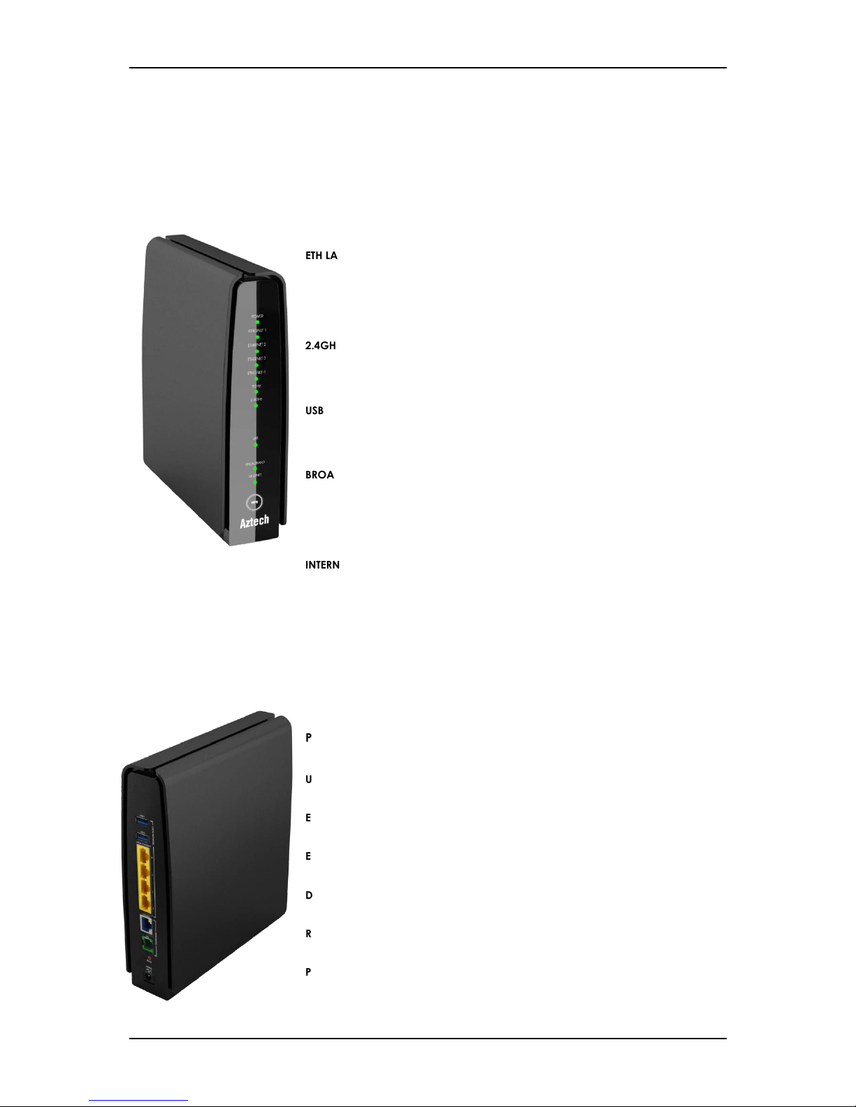
LED STATUS DESCRIPTION
POWER Off No power is supplied to the device
Green (Steady) Connected to a power supply
ETH LAN 1-4
Off
There is no device connected to the
corresponding port
Green (Steady)
There is a device connected to the
corresponding port
Green (Blinking) A device connected to the corresponding
port is actively transmitting/receiving data
2.4GHz/5.0GHz Off Corresponding wireless interface is disabled
Green (Steady) Corresponding wireless Interface is enabled
Green (Blinking) Corresponding wireless interface is actively
transmitting/receiving data
USB Off There is no USB connected to the
corresponding USB port
On There is a USB connected to the
corresponding USB port
BROADBAND Green (Blinking) Device is attempting to detect and connect
to a DSL network
Green (Steady) There is a device connected to the
corresponding port
OFF No device is connected to the corresponding
port
INTERNET Off Modem turned off or unavailable
Green (Steady) Device has successfully established a
connection.
Green (Blinking) Device is actively transmitting/receiving data
Red (Steady) Device failed to establish a connection
WPS Off WPS disabled/inactive
Green (Blinking) WPS authentication in-progress
PORT/BUTTON DESCRIPTION
USB 1 & 2 For USB devices such as printers and USB external hard drives
ETHERNET 1 - 4 Connecting computers and other Ethernet devices
ETHERNET WAN For WAN connection through an Ethernet cable
DSL / LINE Connecting the modem to an ADSL line
RESET To reset the router to the factory default configuration
POWER Adapter input
Device Design
Front Panel
Back Panel
Page 7
User Manual
Page 7 of 52
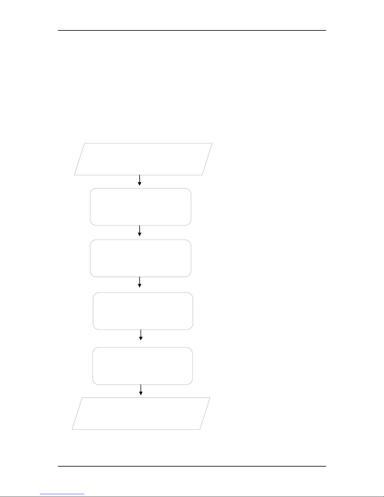
Getting Started
Setting up the device is easy. The flowchart below provides an outline of the
steps needed in order to complete the installation. Brief descriptions appear
beside each step. Detailed instructions are provided in the subsequent
pages.
You may need to check some
settings or disable some applications
before proceeding with the
installation.
Connect the telephone cables,
Ethernet cables, and power
adapter.
For ADSL subscribers, use the Quick
Start Web GUI to setup your PPPoE
connection.
The Web User Interface is primarily
available for ADSL subscribers. Fibre
Subscribers, however, need not to
configure their Internet Connection
method since these are already pre-
configured (except for TM Unifi
subscribers).
Remove/Disable
Conflicts
Plan your Network
Ready to Use
Setup the
Router
Connect to the
Internet
Web Interface
Use Quick Setup
You may see the suggested network
setup for ADSL and Fibre Subscribers.
Page 8
User Manual
Page 8 of 52
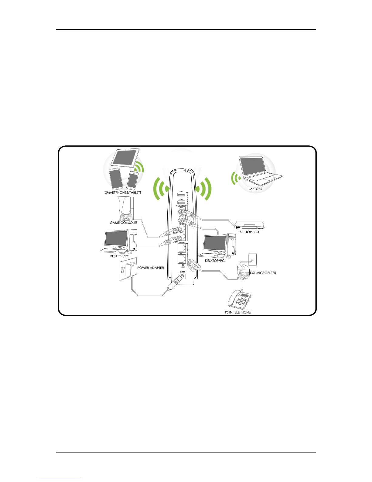
Planning Your Network
Before moving ahead to setup your network, it is a good idea to draw out a
network diagram to help identify your network devices and plan out how to
connect these devices.
Separate network diagrams are provided for both ADSL and Fibre subscribers.
For ADSL Subscribers:
Each port in the router can be used for different connections. For example:
Ethernet 1 – Mom’s Computer
Ethernet 2 – Game Console
Ethernet 3 – Dad’s Computer
Ethernet 4 – Set Top Box
DSL/LINE - DSL Microfilter
*Ethernet port 4 is primarily
reserved for Set Top Box
Page 9
User Manual
Page 9 of 52
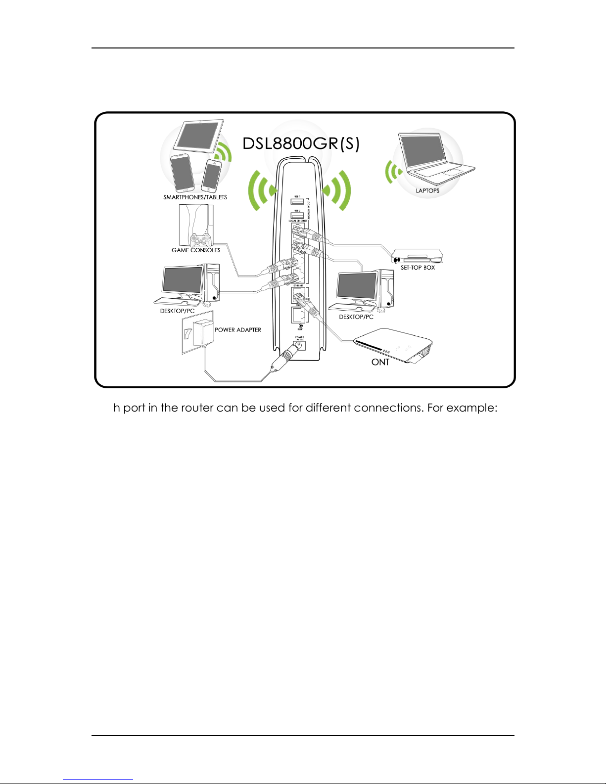
For Fibre Subscribers:
Each port in the router can be used for different connections. For example:
Ethernet 1 – Mom’s Computer
Ethernet 2 – Game Console
Ethernet 3 – Dad’s Computer
Ethernet 4 – Set Top Box
Ethernet WAN – ONT
To create a network diagram:
For wireless devices, identify the wireless devices you want to include in
the network
For wired devices, identify which router port you want to use for each
device.
*Ethernet port 4 is primarily
reserved for Set Top Box
Page 10

User Manual
Page 10 of 52
Remove or Disable Conflicts
To ensure that the router installation moves on smoothly, you need to remove
or disable conflicts that may interfere with the installation. Probable conflicts
may include:
Internet sharing applications
Proxy software
Security software
TCP/IP settings
Internet properties
Temporary Internet files
Internet Sharing, Proxy, and Security Applications
Internet sharing, proxy software, and firewall applications may interfere with
the router installation. These should be removed or disabled before starting
the installation.
If you have any of the following or similar applications installed on your
computer, remove or disable them according to the manufacturer’s
instructions.
Internet Sharing
Applications
Proxy Software
Security Software
Microsoft Internet Sharing
WinGate
Symantec
WinProxy
Zone Alarm
Page 11

User Manual
Page 11 of 52
Configuring TCP/IP Settings
Check if your computer uses the default TCP/IP settings.
To check the TCP/IP properties:
1. Select Start > Run. The Run dialog box would appear.
2. Enter control ncpa.cpl on the input box, and then click the OK button.
This would open the Network Connections window in your computer.
3. Right-click LAN and then select Properties. The Local Area Connection
Properties dialog box would appear.
4. Select Internet Protocol (TCP/IP) and then click Propertie’. The Internet
Protocol (TCP/IP) dialog box would appear.
5. Select Obtain an IP address automatically.
6. Click the ‘OK’ button to close the Internet Protocol (TCP/IP) dialog box.
7. Click the ‘OK’ button to close the Local Area Connection Properties
dialog box.
Configuring Internet Properties
To set the Internet Properties:
1. Select Start > Run. This opens the Run dialog box.
2. Enter control inetcpl.cpl and then click OK to open the Internet
Properties window.
3. Click on the Connections tab.
4. On the Dial-up and Virtual Private Network settings pane, select Never
dial a connection.
5. Click OK to close Internet Properties.
Page 12

User Manual
Page 12 of 52
Removing Temporary Internet Files
Temporary Internet files are files from Web sites that are stored in your
computer. Delete these files to clean the cache and remove footprints left by
the Web pages you visited.
To remove temporary Internet files:
1. Select Start > Run to open the Run dialog box.
2. Enter control and then click the OK button to open the Control Panel.
3. Double-click Internet Options.
4. On the Internet Options window, in the Temporary Internet Files pane,
click Delete Cookies.
5. Click Delete Files.
6. Click OK to close Internet Properties.
Page 13
User Manual
Page 13 of 52
Setup the Device
When installing the router, find an area where there are enough electrical
outlets for the router, the main computer, and your other computer devices.
NOTE: Different setup procedures are provided for both ADSL and Fibre
subscribers.
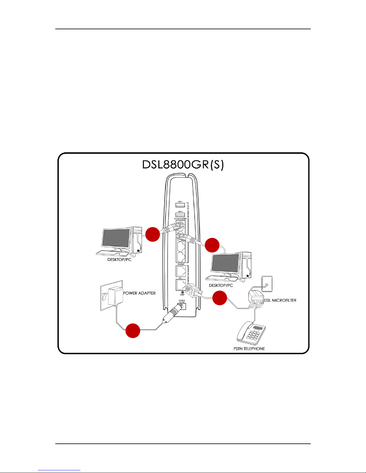
For ADSL Subscribers:
For ADSL subscribers, please follow the instructions below in setting up your
device:
1. Plug one end of the Ethernet cable from the router’s Ethernet port and
then plug the other end into the Ethernet port of your computer.
1
2
3
4
Page 14

User Manual
Page 14 of 52
2. If you have another device that you need to connect into the router,
use another Ethernet cable. Plug one end of an Ethernet cable from
the computer’s Ethernet port and then plug the other end into an
available Ethernet port in the router.
3. Plug one end of the telephone cable from the DSL Microfilter’s ADSL
port and then plug the other end into the router’s DSL port.
DSL Microfilter
Your phone line carries with it both phone calls and Internet signals.
When you are using the Internet, the connection produces high-
pitched tones that can affect your voice calls when using the phone.
Installing a DSL Microfilter separates the two signals and eliminates
the noise.
To setup a telephone on the DSL Microfilter:
a. Locate the phone jack in your house.
b. Insert the DSL Microfilter into the phone jack.
c. Plug one end of the telephone cable from the DSL Microfilter’s TEL
port and then plug the other end into the telephone.
4. Connect the power adapter from the router’s 19V 1.89A DC port into
the power outlet.
Page 15
User Manual
Page 15 of 52
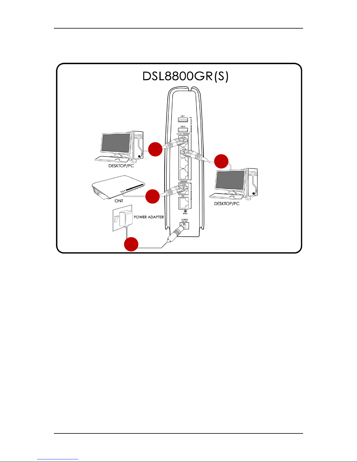
For Fibre Subscribers:
For Fibre subscribers, please follow the instructions below in setting up your
device:
1. Plug one end of the Ethernet cable from the router’s Ethernet port and
then plug the other end into the Ethernet port of your computer.
2. If you have another device that you need to connect into the router,
use another Ethernet cable. Plug one end of an Ethernet cable from
the computer’s Ethernet port and then plug the other end into an
available Ethernet port in the router.
3. Using another Ethernet cable, plug one end of an Ethernet cable to
the WAN port of your router, and then plug the other end to the
available Ethernet port of your ONT.
4. Connect the power adapter from the router’s 19V 1.89A DC port into
the power outlet.
1 2 3
4
Page 16
User Manual
Page 16 of 52
About the Web User Interface
The Web User Interface is used to configure your router’s settings. The Web
User Interface also allows ADSL subscribers to configure and ready your
internet settings for first use.
Fibre Subscribers, however, need not to configure their Internet Connection
method since these are already pre-configured in ONT devices and are
loaded in your router once connected except for TM Unifi subscribers.
NOTE: Fibre TM Unifi Home still requires a username and password to be
keyed-in.
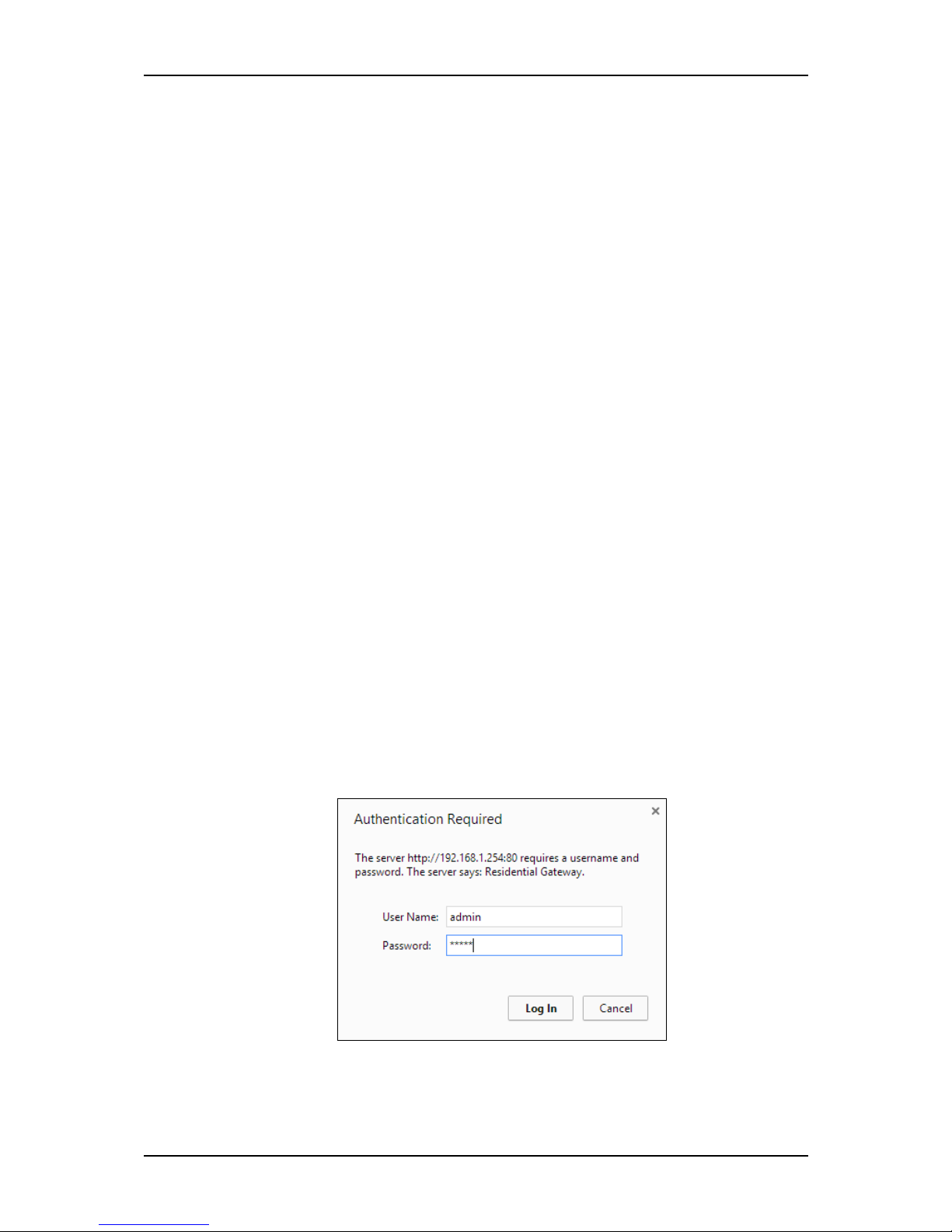
Accessing the Web User Interface
To access the Web User Interface:
1. Open your web browser.
2. Type-in 192.168.1.254 on the address bar and then press Enter.
3. You will be prompted to enter a username and password for
authentication. Type
admin
as its username and
admin
as its password
then click Log In.
4. You will be redirected to the Web User Interface of your DSL8800GR(S)
device.
Page 17

User Manual
Page 17 of 52
Web User Interface Menu
The DSL8800GR(S) Web User Interface includes the following menus:
Quick Setup
Local Network Configuration
Device Status
Statistics
Applications
Device Administration
Some menus include several sub menus which would be discussed in the
subsequent pages.
Quick Setup
This is the DSL8800GR(S) Web User Interface’s initial page. You would
automatically be redirected to this page once you access your router’s Web
User interface.
It contains two sub menus:
Quick Internet Setup
Wireless
Page 18

User Manual
Page 18 of 52
Quick Internet Setup
Your router has an auto connection feature that automatically detects
active connections on its Ethernet WAN and DSL port.
Before proceeding, it is important to take note of the following:
ADSL Subscribers are advised to consult their respective Internet Service
Providers for the details of their internet connection access. Take note
that it is important to ensure that you have followed the setup for ADSL
subscribers.
Fibre Subscribers, however, need not to configure their Internet
Connection method since these are already pre-configured in ONT
devices and are loaded in your router once connected except for TM
Unifi subscribers.
Page 19

User Manual
Page 19 of 52
This page easily allows you to determine or set parameters for the following:
Connection Status. Displays the model of your router, the Basic MAC
Address, its Serial No., and your router’s Firmware Version.
Connection Method.
Allows you to set your router’s method of
connection. By default the Connection Method is set to ‘
Auto
’. This
default setting allows your router to automatically detect active
connections on your router’s Ethernet WAN and DSL port.
NOTE: You may change the connection method, however, it is strongly
advised to leave the Connection Method as AUTO.
To change the connection method:
1. Select the preferred connection method.
2. Click the Save button to apply changes.
3. Refresh page for the Service Provider selection list to update.
Service Provider. This function directly corresponds to your Connection
Method. After selecting a connection method, a selection list would be
available on the Service Provider’s drop down menu. By default, the
Service Provider drop down menu corresponds to the ‘Auto’
Connection Method.
Page 20

User Manual
Page 20 of 52
To select a service provider:
1. On the Service Provider drop down menu, select your Internet
Service Provider (ISP).
2. If prompted by your ISP, input correctly the Username and Password
given to you by your ISP then press enter. If entered correctly, you
now have access to the internet.
Page 21

User Manual
Page 21 of 52
Wireless
Allows you to configure features for both the 2.4GHz and 5.0GHz wireless LAN
interface. The internet surfing experience is likely to improve on 5.0GHz with
probably lesser wireless interference, however the 5.0GHz SSID can only be
detected if your end device supports 5.0GHz wireless interface as well.
This page also allows you to Enable/Disable WPS setup. It also allows you to
view the WPS AP Pin.
To configure 2.4GHz/5.0GHz Wireless Band:
1. On the Web User Interface, click Quick Setup then click Wireless.
2. By default the Wireless Feature is Enabled.
3. If you want to hide the Network from active scans, simply tick the Hide
SSID checkbox.
4. Input your preferred Wireless Network Name (SSID) for your wireless
network.
Page 22

User Manual
Page 22 of 52
5. It is highly recommended to select the “Auto” mode for Channel
setting, this will allow your router to connect to the least congested Wi-
Fi channel at all times.
6. Select a Network Authentication method on the drop down list. By
default this is selected as Mixed WPA2/WPA-PSK.
7. Enter your preferred Network Key (Password).
8. Click the Save/Apply button to save and apply wireless settings.
Wi-Fi Protected Setup. Your router’s WPS button allows you to activate WiFi
Protected Setup (WPS). When you press the WPS button, it automatically
detects and connects wireless clients into the wireless network by
broadcasting the wireless network settings from your Access Point to you
wireless device/s.
It is important to take note of the following before using the WPS function:
The WPS function of your router must first be enabled before you can
use Wi-Fi Protected Setup.
WPS can only be used with wireless client devices that also have a WPS
feature. You may consult your Wireless client’s user guide to verify if
your device has a WPS feature.
The WPS feature is available both for 2.4GHz wireless clients and 5.0GHz
wireless clients.
To enable or disable WPS function:
1. On the WPS Setup section, choose whether to disable or enable the
WPS.
2. You may also copy the WPS AP Pin for future use.
3. Click the ‘Save/Apply’ button to apply changes.
Page 23

User Manual
Page 23 of 52
To connect to your router via WPS:
1. Press the WPS button of your router for two seconds, or until the LED of
the WPS button starts to blink.
2. Within 2 minutes, press the WPS button of your Wireless Client.
Note: WPS can only be used with wireless devices that have a
compatible WPS feature.
Page 24

User Manual
Page 24 of 52
Local Network Configuration
This menu allows you to configure Local Area Network settings and DHCP
server settings, configure VPN and Public IP Pass Through, and set DHCP IP
Reservations.
This menu contains the following sub menus:
Settings
DHCP IP Reservation
Page 25

User Manual
Page 25 of 52
Settings
Allows you to configure the DSL Router’s IP Address, Subnet Mask, Host Name
and Domain name for your Router’s LAN interface. You may also Disable or
Enable and configure the DHCP server, and enable or disable the Public IP
Pass through and the VPN Pass through settings of your router. Remember to
click the Save/Reboot button to apply the changes.
Page 26

User Manual
Page 26 of 52
DHCP IP Reservation
This page allows you to manually reserve a device’s IP and MAC address for
your router’s DHCP server. It also displays the Reserved Devices table which
shows the Hostname, MAC Address, IP Address, and the corresponding
interface of reserved devices.
To manually reserve devices:
1. Enter the MAC and IP address of your device.
To know the MAC and IP address of your computer simply do the
following :
b. On the Start Menu, click Run.
c. On the Input box of the Run window, type in: ‘cmd’ to open
the command prompt.
d. On the command prompt key in ‘ipconfig/all’.
Page 27

User Manual
Page 27 of 52
e. Locate the Ethernet adapter Ethernet section and find the
‘Physical Address’ (MAC Address) and the ‘IPV4 address’ (IP
Address) on the section’s list.
2. Enter your preferred Host Name.
NOTE: The max length for a Hostname is 40 characters.
3. Check if all entered parameters are correct.
4. Click the ‘Add’ button to reserve the device.
5. Click the ‘Save’ button to save applied settings.
To remove reserved devices:
1. Determine the Host Name of the device you wish to remove on the
Reserved Devices table.
2. Tick the check box that corresponds to the device that you wish to
remove.
3. Click the ‘Remove’ button to remove the reserved device.
Page 28

User Manual
Page 28 of 52
Device Status
This page displays the System Information, Internet Status, and DHCP Leases,
which previews the status and related information of your system, your
internet status and your DHCP assigned devices respectively.
Page 29

User Manual
Page 29 of 52
Statistics
Allows you to view your router’s network status for ADSL, Internet, WLAN and
Wireless LAN respectively. This page also allows you to reset the statistics of
each network.
DSL. Reflects the current status of your internet connection. Information
such as Mode, DSL Status, Downstream and Upstream of various
properties are displayed in this page.
Internet. Displays both Received and Transmitted status of Bytes,
Packets, Errors and Drops of your Internet connection.
WLAN. Displays both Received and Transmitted status of Bytes, Packets,
Errors and Drops for each WLAN interface.
LAN. Displays both Received and Transmitted status of Bytes, Packets,
Errors and Drops for each Ethernet interface.
Page 30

User Manual
Page 30 of 52
Applications
Allows you to configure Firewall Settings, add or remove Port Forwarding and
Port Triggering Rules, change Parental Control settings, change the DMZ host,
add or remove a Dynamic DNS address, and view USB Storage status.
The Applications menu has the following sub menus:
Firewall Settings
Port Forwarding
Port Triggering
Parental Control
DMZ
DDNS
USB Storage
Page 31

User Manual
Page 31 of 52
Firewall Settings
This page allows you to configure Incoming/Outgoing IP Traffic for both ADSL
and Fibre by either Blocking or Accepting specific data traffic to and from
the Internet. This page also allows you to view the status of TCP/IP sessions, as
well as designate the TCP and UDP idle timeout.
To add a Filter :
1. Enter the Filter Name.
2. Determine the Direction on the Direction’s drop down list. By
default ‘Incoming’ is selected.
3. Select the Protocol to be implemented to the filter.
4. Enter other corresponding details (e.g. Source IP Address, Source
Subnet Mask, Source Port, etc.).
5. Tick the checkbox of the corresponding WAN interface/s where
the filter would apply.
6. Click the ‘Save/Apply’ button to apply changes.
Page 32

User Manual
Page 32 of 52
To remove a filter:
1. On the Filter list table, tick the checkbox that corresponds to the
filter that you wish to remove.
2. Click the ‘Remove’ button to apply.
To change TCP/UDP Idle Timeout:
1. Determine the parameter (TCP or UDP) that you wish to change.
2. On the TCP and or UDP’s input box, input the desired Idle
Timeout.
3. Click the ‘Save’ button to apply changes.
Page 33

User Manual
Page 33 of 52
Port Forwarding
Certain applications need to access a specific port for communication over
the network or Internet. Port Forwarding allows you to configure your router to
forward incoming and outgoing data transmissions for these applications to
be forwarded to a specific port or port range on your computer. You are
allowed to maintain 32 Port Forwarding entries in your router.
To add a new port forwarding rule:
1. Select the interface to be used on the Use Interface drop down list.
2. Determine the Server Name.
You may opt to simply select a service from the drop down list
provided or use a custom server name if the service you want to
use is not included on the drop down list presets.
NOTE: Services from the drop down list are pre-configured with Port
numbers. You may opt to add port numbers, however, the "Internal
Page 34

User Manual
Page 34 of 52
Port Start/End" would immediately reflect the keyed values from the
“External Port Start/End” input boxes, vice versa.
3. Enter the Server IP address.
4. Key in or add External Port Starts and Ends, and the Protocols to be
implemented for each port.
5. Click the ‘Save/Apply’ button to apply changes.
To remove a port forwarding rule:
1. On the Port Forwarding List, tick the checkbox that corresponds to the
rule that you want to remove.
2. Click the ‘Remove’ button to remove the rule.
Page 35

User Manual
Page 35 of 52
Port Triggering
Some applications require that the remote parties open the specific ports in
the router’s firewall for access. For instance, an application uses port 25 for
requests and port 113 for replies. If a computer on the LAN connects to port
25 on a remote server hosting this application, using Port Triggering on the
router, incoming connections to port 113 (from the remote server) could be
redirected to the PC that initiated the request. A maximum of 32 Port
Triggering entries can be configured.
To add a new port triggering rule:
1. Select the interface to be used on the Use interface drop down list.
2. Key in the Application Name:
You may opt to simply select an application from the drop down list
provided or use a custom application name if the application you
want to use is not included on the drop down list.
Page 36

User Manual
Page 36 of 52
3. Input or add External/Open Port Starts/Ends, and the Protocols to
be implemented for each port.
4. Click the ‘Save/Apply’ button to apply changes.
To remove a port triggering rule:
1. On the Port Triggering List, tick the checkbox that corresponds to
the rule that you want to remove.
2. Click the ‘Remove’ button to remove the rule.
Page 37

User Manual
Page 37 of 52
Parental Control
Parental Control allows you to apply router access restrictions among LAN
devices within specific times in a day. This allows you to limit a device’s
internet access at certain amounts of time within a week. A maximum of 16
restriction rules can be created.
To add an Access Time Restriction rule:
1. Enter a User Name for the restriction.
2. Enter the device MAC Address.
If the device has already been added, you may select the mac
address on the drop down menu of the Attached Client’s Mac Address.
However, if it is a new device, you may input the MAC address of the
device that you wish to restrict on the Other MAC Address input box.
To know the MAC address of your computer simply do the following :
a. Click Run.
Page 38

User Manual
Page 38 of 52
b. On the Input box of the Run window, type in: ‘cmd’ to open the
command prompt.
c. On the command prompt, key in ‘ipconfig/all’.
d. Locate the Ethernet adapter Ethernet section and find the
‘Physical Address’ on the list provided. This is your pc’s unique
Physical MAC Address.
3. Tick the box that corresponds to the days of the week the rule will
apply on (e.g. school days : Monday to Friday).
4. Designate a Start Blocking Time and End Blocking time.
NOTE: Time designation is in 24 hour (hours:minutes) format (e.g.
homework hour Start time 4:30PM – 16:00, End Time 6:30PM or 18:30)
Page 39

User Manual
Page 39 of 52
DMZ Host
If a computer is assigned as a DMZ Host, it will receive all the data from the
Internet that does not belong to the list of applications configured in Port
Forwarding.
To enable a DMZ Host IP Address:
1. Enter the LAN IP address of the PC you wish to set as DMZ Host in the
DMZ Host IP Address input box.
2. Click the ‘Save/Apply’ button to apply changes.
If you need to disable the DMZ Host, simply click the Remove button and the
DMZ Host IP Address input box would be empty.
Page 40

User Manual
Page 40 of 52
DDNS
Your router offers a Dynamic Domain Name System (DDNS) feature. DDNS lets
you assign a fixed host and domain name to a dynamic Internet IP Address. It
is useful when you are hosting your own website, FTP server, or other servers
behind the router.
Before using this feature, you need to sign up for DDNS service providers. The
router supports these popular Dynamic DNS service providers:
www.dyndns.org
www.tzo.com
Using DynDNS.org / TZO
1. On the D-DNS provider drop down list, select your DDNS provider.
2. Designate a Hostname for the DDNS profile.
3. Select an interface on the Interface drop down selection list.
Page 41

User Manual
Page 41 of 52
To remove a DDNS setting:
1. On the DDNS configuration list, tick the box that corresponds to the
profile that you wish to remove.
2. Click the Remove button to remove the profile.
Page 42

User Manual
Page 42 of 52
USB Storage
Allows you to view the status of USB Storage devices plugged in your router’s
USB ports such as Total, Used, Free, and Mount Point. This page also allows
you to Mount/Unmount plugged USB storage devices.
NOTE: If a USB device has been plugged and cannot be detected, click the
Refresh button to refresh the USB information list.
Accessing USB Storage Devices
1. Ensure that the DSL8800GR(S) router is OFF, connect the USB storage
device and switch it ON.
2. Once the DSL8800GR(S) is ready, click on the Start Button> Run.
3. On the Run window input box, type in \\192.168.1.254 and click on OK,
a Windows explorer window would appear. If there is a prompt for a
username and password, type admin for username and admin for
password.
Page 43

User Manual
Page 43 of 52
4. From the windows explorer window, you will see a folder called USB1_1
(for USB port 1) or USB2_1 (for USB port 2). These folders contain your USB
storage device contents.
Safely Removing the USB Storage Device from you DSL8800GR(S)
1. On the Applications menu, click on USB Storage.
2. You can safely remove the device by clicking the ‘Unmount’ button
displayed on USB1 or USB2 information table.
Note: The USB Storage feature on the DSL8800GR(S) can only support
devices that are formatted with FAT/FAT32 file systems. NTFS and other
file systems are currently not supported.
Page 44

User Manual
Page 44 of 52
Device Administration
Configuration
You may use this utility to backup the router’s configuration as a file on your
PC, restore the router’s setting using the saved configuration, and to reset
your router to its factory default settings.
To backup your router’s configuration:
1. On the System - Backup section, click on the Backup button.
2. Select the folder on your pc where you want the ‘backupsettings.conf’
file to be saved.
3. Click OK.
Page 45

User Manual
Page 45 of 52
To restore router settings using saved configuration:
1. On the Update Settings section, click on Update.
2. Click on the Choose File button, and locate the backupsettings.conf
file and click ok.
3. Wait for the router to finish the process. Your router has now restored its
previous settings.
To reset your router to its factory default settings:
1. On the System Restore Default settings, click the Restore button. Your
router would immediately restore its settings to default settings.
Page 46

User Manual
Page 46 of 52
Firmware Upgrade
This page allows you to update the current firmware available on your router.
However, it is advised to update your firmware if suggested by your ISP or
update the firmware with an approved Aztech firmware.
To upgrade the router’s firmware simply do the following steps:
1. On the Firmware Upgrade, click on the Choose File button.
2. Locate the firmware file and click Open.
3. Click the Update Software button, to update the firmware of your
router.
4. Wait for the router to finish updating. You will be redirected to the
Quick Setup page after a successful firmware upgrade.
Page 47

User Manual
Page 47 of 52
Internet Time
This page enables your Internet Time to automatically synchronize your
router’s time with a time-server when connected to the Internet.
To modify the internet time:
1. Tick the Automatically synchronize with Internet time servers checkbox.
2. Select the time server for the First to fifth time server drop down
selection lists.
3. Select a Time zone offset.
4. Click the ‘Save/Apply’ button to apply changes.
Page 48

User Manual
Page 48 of 52
User Password
This page allows you to set user level authorization for additional security
purposes on your router. This means that you would be restricting any
unauthorized access to your router’s GUI by implementing a password to your
Web User Interface.
To configure the user password:
1. Tick the ‘Enable Password’ check box.
2. Input the old password.
3. Input the new password, and confirm the new password.
4. Click the ‘Save/Apply’ button to apply changes.
Page 49

User Manual
Page 49 of 52
System Log
If the log mode is enabled, the system will begin to log all the selected
events.
For the Log Level, all events above or equal to the selected level will
be logged.
For the Display Level, all logged events above or equal to the
selected level will be displayed.
If the selected mode is 'Remote' or 'Both,' events will be sent to the
specified IP address and UDP port of the remote syslog server.
If the selected mode is 'Local' or 'Both,' events will be recorded in the
local memory.
Select the desired values and click the 'Save/Apply' button to configure the
system log options.
Page 50

User Manual
Page 50 of 52
Access Control
This feature allows you to manage the user access rights for remote access
management. It also allows you to enable or disable protocols running on
your router.
To enable/disable services:
1. On the Services table simply tick/untick the protocol you wish to
enable/disable (for HTTP service, you may key-in a specific port that
the service will use).
2. Click the ‘Save/Apply’ button to save and apply changes.
Page 51

User Manual
Page 51 of 52
Safety Precautions
Do not open, service, or change any component.
Only qualified technical specialists are allowed to service the
equipment.
Observe safety precautions to avoid electric shock
Check voltage before connecting to the power supply. Connecting to
the wrong voltage will damage the equipment.
Page 52

User Manual
Page 52 of 52
Copyright © 2013 Aztech Technologies Pte Ltd (CRN:199800635M). All rights reserved.
 Loading...