

Page 1
Ethernet USB Router
User Manual
VERSION 1.0
VERSION 1.0
VERSION 1.0VERSION 1.0
Page 2

User Manual
Page 2 of 90
Page 3

Contents
User Manual
About this Manual .........................................7
About the Router ...........................................8
Requirements...........................................................................8
Software..........................................................................................................8
Hardware.........................................................................................................8
Package Contents .................................................................... 9
Device Design ........................................................................10
Front Panel ....................................................................................................10
Back Panel.....................................................................................................11
Getting Started ............................................12
Remove or Disable Conflicts .................................................13
Internet Sharing, Proxy, and Security Applications ......................................13
Configuring TCP/IP Settings ..........................................................................14
Configuring Internet Properties.....................................................................14
Removing Temporary Internet Files .............................................................15
Hardware Setup .....................................................................16
Ethernet Connection......................................................................................16
USB Connection .............................................................................................17
About the Web Interface .............................19
Page 3 of 90
Page 4

User Manual
Accessing the Web Manager.................................................19
Components ...........................................................................19
Buttons ..........................................................................................................19
Commands ....................................................................................................20
Menus............................................................................................................20
Basic Menu...................................................21
Home ......................................................................................22
Connection Information ................................................................................22
Router Information........................................................................................22
Local Network Information ...........................................................................22
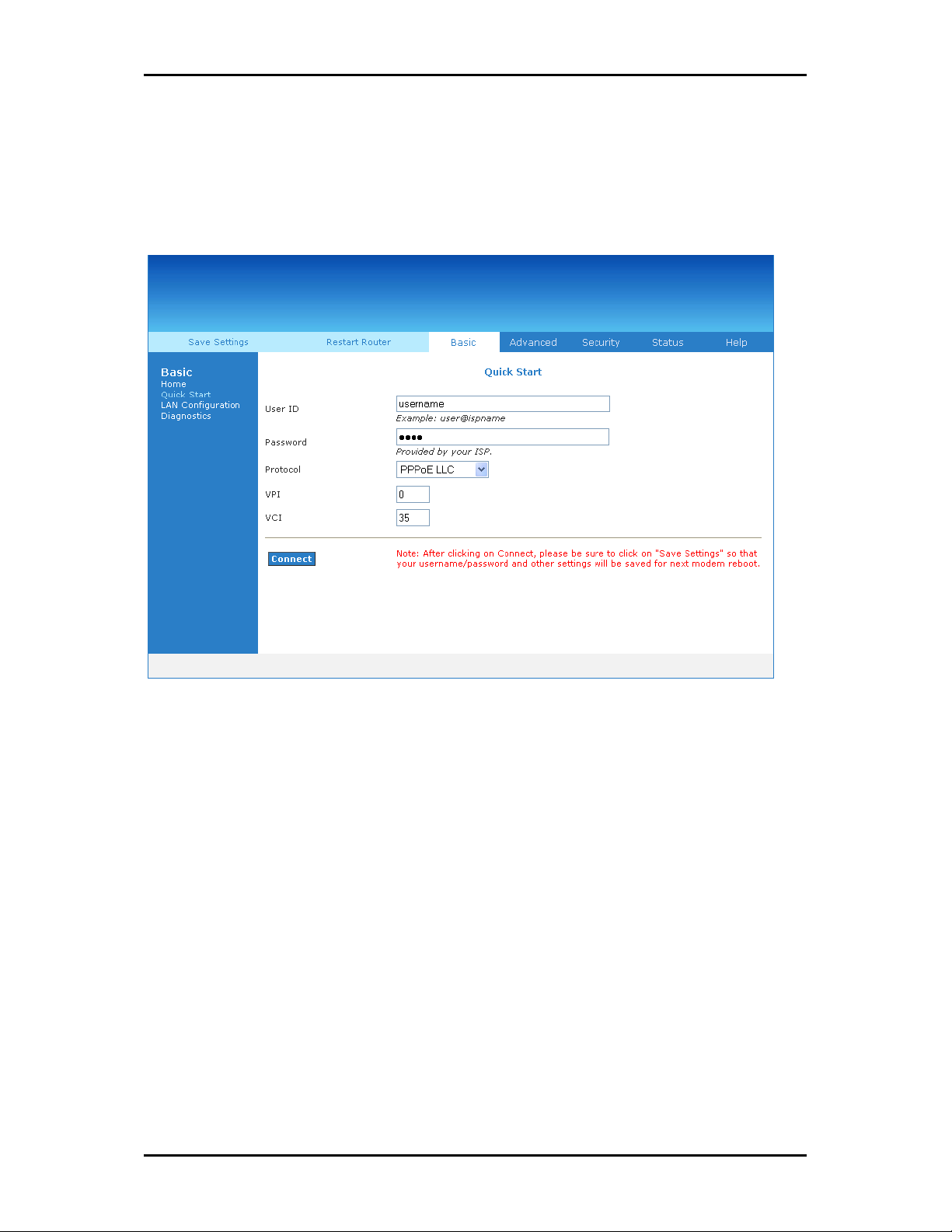
Quick Start ..............................................................................22
LAN Configuration..................................................................23
Diagnostics .............................................................................24
Ping Test........................................................................................................25
Full Modem Test............................................................................................25
Advanced Menu ...........................................26
WAN........................................................................................27
New Connection............................................................................................27
Connection Scan ............................................................................................34
LAN..........................................................................................35
LAN Configuration .........................................................................................35
LAN Group Configuration...............................................................................37
Assign ISP DNS, SNTP ....................................................................................40
LAN Clients ....................................................................................................40
Page 4 of 90
Page 5

User Manual
Applications............................................................................42
Universal Plug and Play ................................................................................43
Simple Network Timing Protocol ..................................................................44
IGMP Proxy ....................................................................................................46
TR-068 WAN Access ......................................................................................48
DNS Proxy......................................................................................................49
Dynamic DNS Client.......................................................................................50
Port Forwarding.............................................................................................51
Bridge Filters .................................................................................................54
Web Access Control .......................................................................................55
Quality of Service...................................................................56
Egress ............................................................................................................57
Ingress...........................................................................................................60
QoS Shaper Configuration .............................................................................65
Policy Routing Configuration.........................................................................69
Routing ...................................................................................71
Static Routing ................................................................................................71
Routing Table ................................................................................................72
System Password...................................................................73
Firmware Update ...................................................................74
Restore to Default..................................................................74
Security Menu ..............................................75
IP Filters.........................................................................................................76
LAN Isolation .................................................................................................78
Status Menu .................................................79
Page 5 of 90
Page 6

User Manual
Connection Status..........................................................................................80
System Log....................................................................................................81
Remote Log ...................................................................................................82
Network Statistics .........................................................................................84
DDNS Update Status......................................................................................85
DHCP Clients ..................................................................................................86
QoS Status .....................................................................................................87
Modem Status ...............................................................................................88
Product Information ......................................................................................88
Help Menu....................................................89
Page 6 of 90
Page 7

User Manual
About this Manual
This manual provides a discussion of the components, basic operation, and advanced
configuration options of the router.
Scope and Purpose
This manual provides installation instructions and description of the router components
and the web interface.
Target Audience
This manual is designed and developed for users who are required to operate and
perform first-level maintenance of the router. It assumes the user of this manual has
basic knowledge and experience in configuring routers, computer networks, and
computer systems.
Document Structure
The manual is divided into the following sections:
Chapter
Chapter About
ChapterChapter
2222 About the Router
3333 Getting Started
4444 About the Web Interface
5555 Setup Menu
6666 Basic Menu
7777 Advanced Menu
9999 Security Menu
10
10 Status Menu
1010
About
AboutAbout
11
11 Help Menu
1111
Page 7 of 90
Page 8

User Manual
About the Router
Congratulations on the purchase of your router. This router allows you to utilize your
phone circuit to access broadband Internet without restricting you to make telephone
calls.
This router is designed to connect to the Internet and to your local area network (LAN)
via universal serial bus (USB) or high speed Ethernet. It has full Network Address
Translation (NAT) firewall, demilitarized zone (DMZ) services, and encryption security
support to block unwanted users from accessing your network. Quality of Service (QoS)
and Policy routing (PR) are also supported. This router is compatible with personal
computers and Apple Macs.
Requirements
Your computer must meet the following minimum requirements.
Software
Operating System:
Windows (98 SE, Me, 2000, XP, XP x64)
Macintosh OS 10.2
Ethernet connections are operating system independent
Browser:
Internet Explorer 4.0
Netscape Navigator 3.02
Hardware
233MHz processor
Page 8 of 90
Page 9

User Manual
CD-ROM Drive
Network adapter (Ethernet or USB)
Package Contents
Package contents are listed below. For any missing items, please contact your dealer
immediately. Product contents vary for different models.
Router
Ethernet cable
Telephone cable
USB Cable
9V Power Adapter
Easy Start Guide
Resource CD
Page 9 of 90
Page 10
User Manual
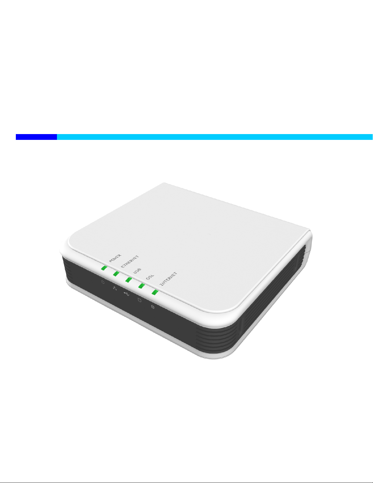
Device Design
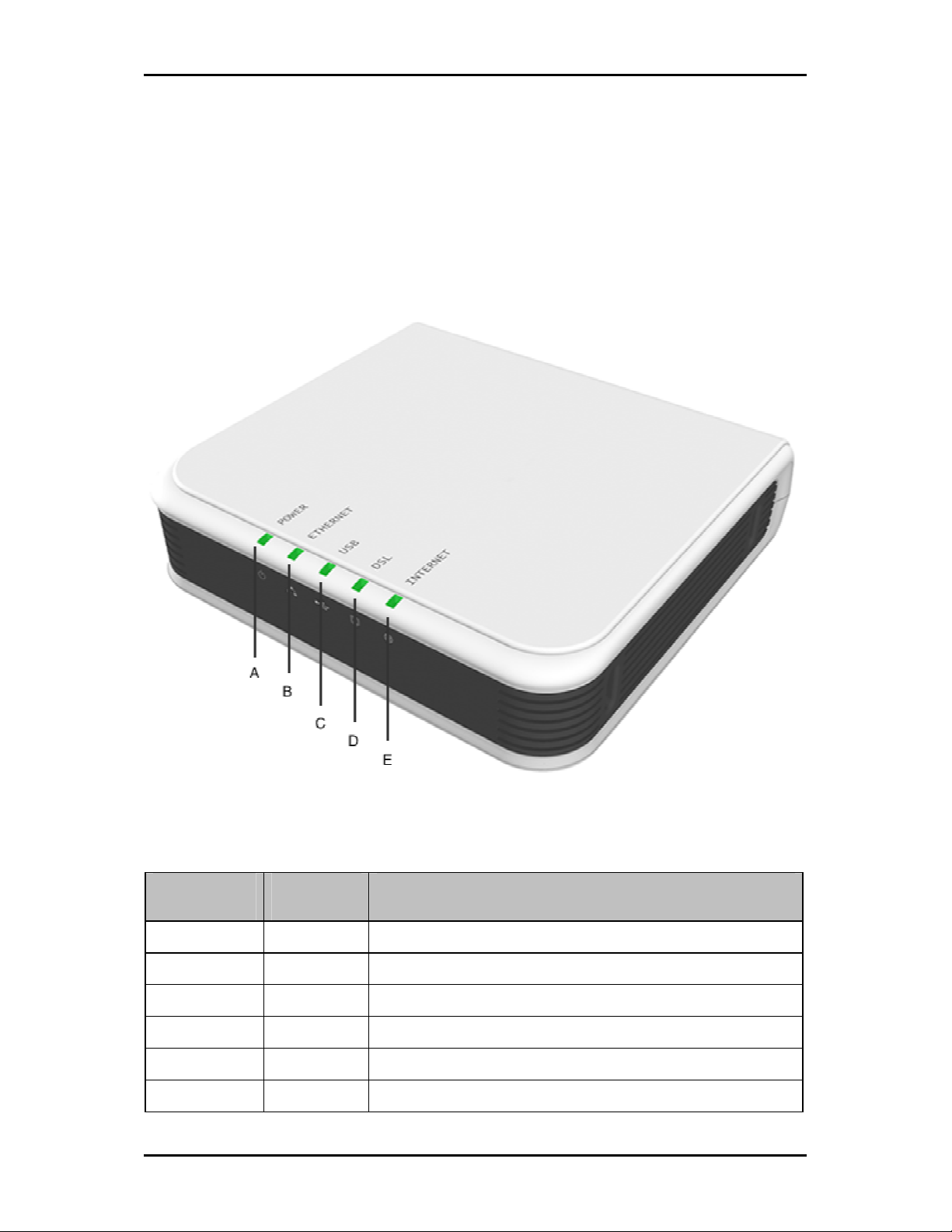
Front Panel
The LEDs on the front panel gives you an idea about the power and connection status.
Front Panel
Front Panel
Front PanelFront Panel
Label
Label Action
LabelLabel
POWER
POWER Off No power is supplied to the device
POWERPOWER
Steady light Connected to an AC power supply
ETHERNET
ETHERNET Off No Ethernet connection
ETHERNETETHERNET
Steady light Connected to an Ethernet port
Blinking light Transmitting/Receiving data
USB
USB Off No USB connection
USBUSB
Page 10 of 90
Action Description
ActionAction
Description
DescriptionDescription
Page 11
User Manual
Steady light Connected to a USB port
Blinking light Transmitting/Receiving data
DSL
DSL Off No DSL signal
DSLDSL
Blinking light Establishing DSL signal
Steady light DSL signal is established
INTERNE
INTERNETTTT Off No Internet connection
INTERNEINTERNE
Steady light Connected to the Internet
Blinking light Transmitting/Receiving data
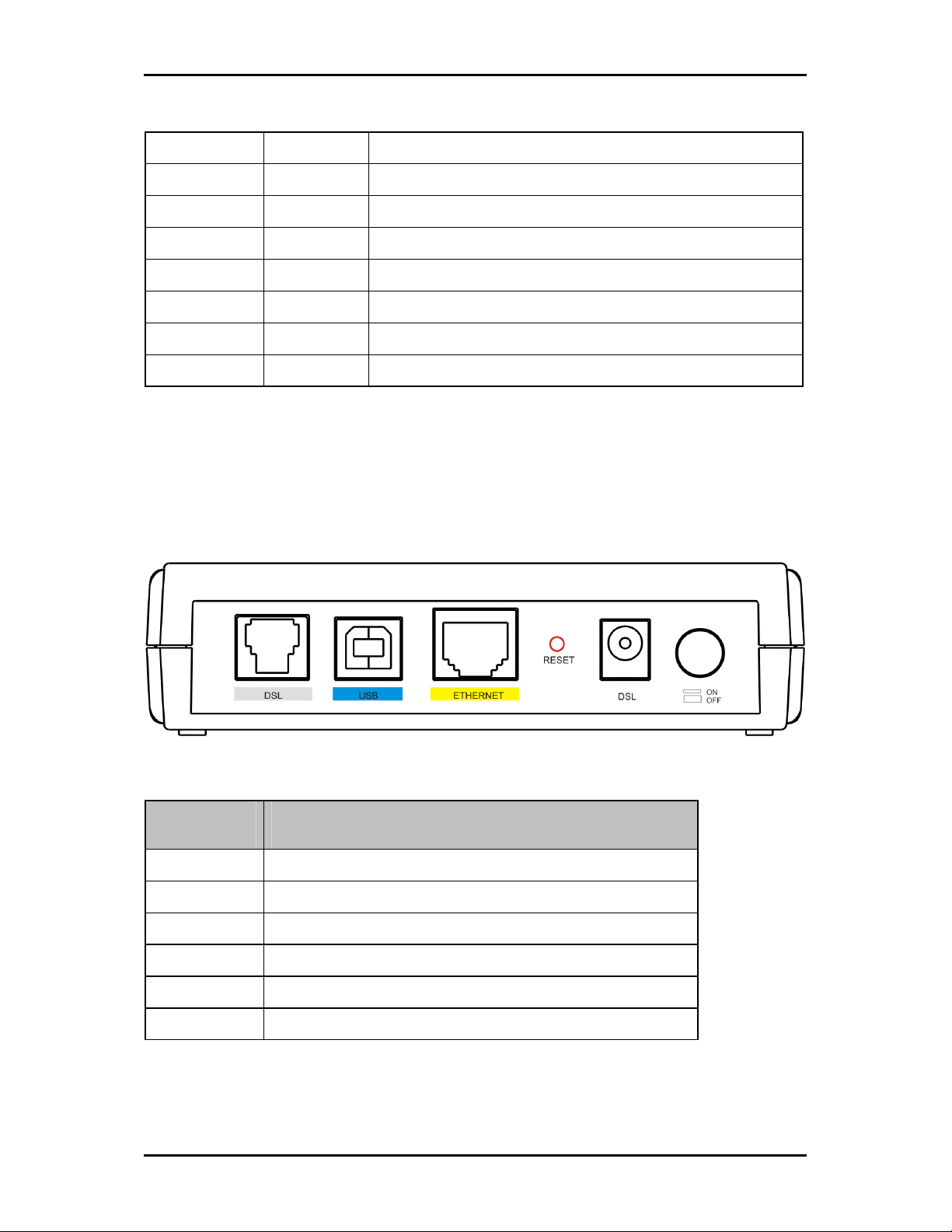
Back Panel
The back panel provides ports to power up and connect the router into the network.
Back Panel
Back Panel
Back PanelBack Panel
Label
Label Used for…
LabelLabel
DSL
DSL Connecting the telephone cable
DSLDSL
USB
USB Connecting with the computer through USB cable
USBUSB
ETHERNET
ETHERNET Connecting with the computer through Ethernet cable
ETHERNETETHERNET
RESET
RESET Resetting the device. Press for 10 seconds to reset.
RESETRESET
Used for…
Used for…Used for…
9 V DC
9 V DC Connecting with the 9V power adapter
9 V DC9 V DC
ON/OFF
ON/OFF Switching the device on/off
ON/OFFON/OFF
Page 11 of 90
Page 12
User Manual
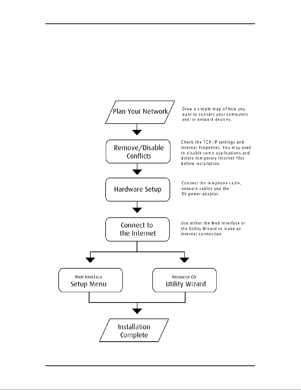
Getting Started
Setting up the device is easy. The flowchart below provides an outline of the steps you
need to complete the installation. There are brief descriptions beside each step to help
you along. Detailed instructions are provided in the subsequent pages.
Page 12 of 90
Page 13

User Manual
Remove or Disable Conflicts
To make sure the router installation moves on smoothly, you need to remove or disable
conflicts that may interfere the installation. Probable conflicts may include:
Internet sharing applications
Proxy software
Security software
TCP/IP settings
Internet properties
Temporary Internet files
Internet Sharing, Proxy, and Security Applications
Internet sharing, proxy software, and firewall applications may interfere with the router
installation. These should be removed or disabled before you install and configure the
router.
If you have any of the following or similar applications installed on your computer,
remove or disable them according to the manufacturer’s instructions.
Internet Sharing Application
Internet Sharing Applicationssss Proxy Software
Internet Sharing ApplicationInternet Sharing Application
Microsoft Internet Sharing WinGate Symantec
WinProxy Zone Alarm
Proxy Software Security Software
Proxy SoftwareProxy Software
Security Software
Security SoftwareSecurity Software
Page 13 of 90
Page 14

User Manual
Configuring TCP/IP Settings
Use the default TCP/IP settings to allow the router to provide a network address to the
computer,
To set the TCP/IP properties:
1. Select Start
2. Enter control
your computer.
3. Right-click LAN
Properties
Properties dialog box.
Properties Properties
4. Select Internet Protocol (TCP/IP)
Protocol (TCP/IP)
Protocol (TCP/IP) dialog box.
Protocol (TCP/IP)Protocol (TCP/IP)
5. Select Obtain an IP address automatically
6. Click OK
7. Click OK
Start > Run
Start Start
control ncpa.cpl
control control
Internet Protocol (TCP/IP) and then click Properties
Internet Protocol (TCP/IP)Internet Protocol (TCP/IP)
Obtain an IP address automatically.
Obtain an IP address automaticallyObtain an IP address automatically
OK to close the Internet Protocol (TCP/IP)
OKOK
OK to close the Local Area Co
OK OK
Run. This opens the Run
RunRun
ncpa.cpl and then click OK
ncpa.cpl ncpa.cpl
LAN and then select Properties
LAN LAN
Internet Protocol (TCP/IP) dialog box.
Internet Protocol (TCP/IP) Internet Protocol (TCP/IP)
Local Area Connection Properties
Local Area CoLocal Area Co
Run dialog box.
Run Run
OK. This opens the Network Connections
OKOK
Properties. This opens the Local Area Connection
PropertiesProperties
nnection Properties dialog box.
nnection Properties nnection Properties
Configuring Internet Properties
Network Connections in
Network Connections Network Connections
Local Area Connection
Local Area Connection Local Area Connection
Properties. This opens the Internet
PropertiesProperties
Internet
Internet Internet
To set the Internet Properties:
1. Select Start
2. Enter control
dialog box.
3. Click Connections
4. In the Dial
connection
connection.
connectionconnection
5. Click OK
Page 14 of 90
Start > Run
Start Start
control inetcpl.cpl
control control
Connections tab.
ConnectionsConnections
OK to close the Internet Properties
OKOK
Run. This opens the Run
RunRun
inetcpl.cpl and then click OK
inetcpl.cpl inetcpl.cpl
Dial----up and Virtual Private Network settings
up and Virtual Private Network settings pane, select Never dial a
DialDial
up and Virtual Private Network settingsup and Virtual Private Network settings
Internet Properties dialog box.
Internet PropertiesInternet Properties
Run dialog box.
Run Run
OK. This opens the Internet Properties
OKOK
Internet Properties
Internet Properties Internet Properties
Never dial a
Never dial a Never dial a
Page 15

User Manual
Removing Temporary Internet Files
Temporary Internet files are files from Web sites that are stored in your computer. Delete
these filed to purge the Internet cache and remove footprints left by the Web pages you
visited.
To remove temporary Internet files:
1. Select Start
2. Enter control
3. Double-click Internet Options
4. In the Temporary Internet Files
5. Click Delete Files
6. Click OK
Start > Run
Start Start
control and then click OK
controlcontrol
Temporary Internet Files pane, click Delete Cookies
Temporary Internet Files Temporary Internet Files
Delete Files.
Delete FilesDelete Files
OK to close the Internet Properties
OKOK
Run. This opens the Run
RunRun
OK. This opens the Contr
OKOK
Internet Options. This opens the Internet Options dialog box.
Internet OptionsInternet Options
Internet Properties dialog box.
Internet PropertiesInternet Properties
Run dialog box.
Run Run
Control Panel
ContrContr
Delete Cookies.
Delete CookiesDelete Cookies
ol Panel.
ol Panelol Panel
Page 15 of 90
Page 16
User Manual
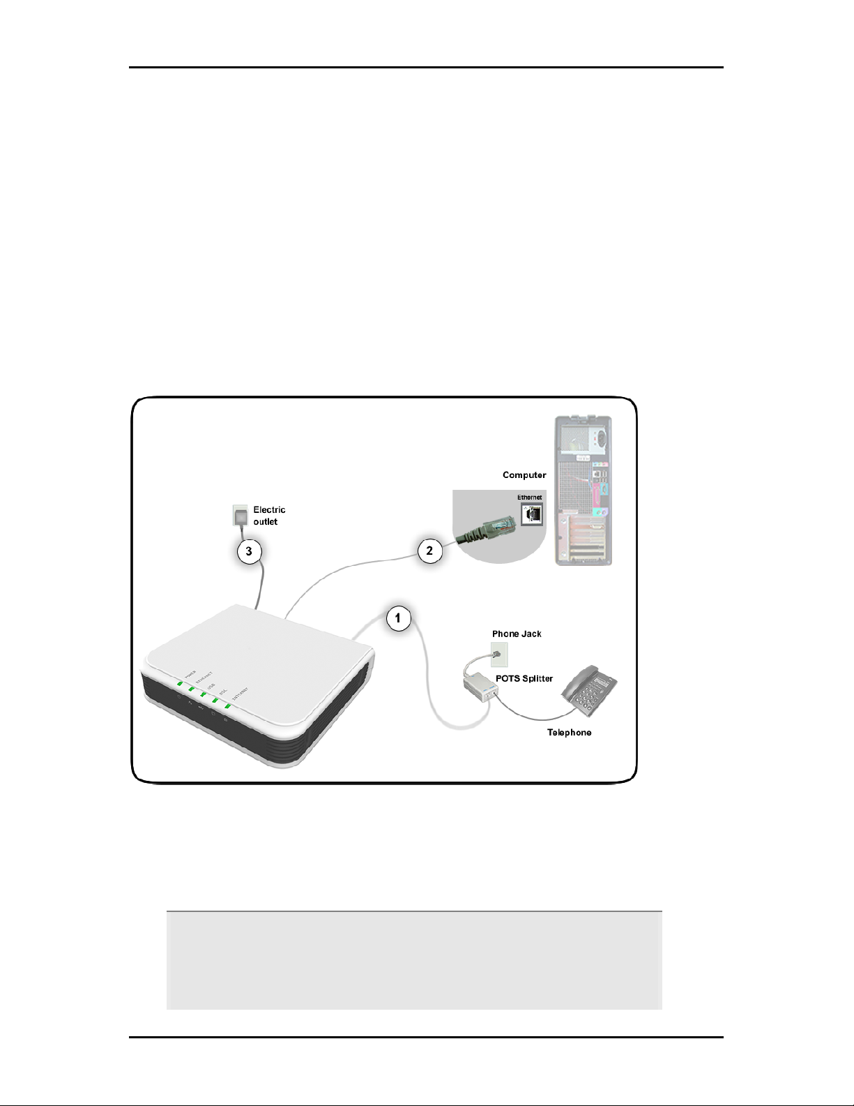
Hardware Setup
When installing the router, the common practice is to have the router, the main
computer, and phone jack in the same room. The room should also have enough
electrical outlets to match your needs.
Ethernet Connection
In terms of data transfer speed, the Ethernet provides the fastest mode of connection
between the router and the computer.
To connect through Ethernet:
1. Plug one end of the telephone cable from the POTS Splitter’s ADSL
plug the other end into the router’s DSL
POTS Splitter
POTS Splitter
POTS SplitterPOTS Splitter
A phone line can carry phone call and Internet signals. When you enable the phone
line for high speed Internet, the connection produces high-pitched tones when using
the phone. Installing a Plain Old Telephone Service (POTS) splitter separates the two
Page 16 of 90
DSL port
DSL DSL
ADSL port and then
ADSL ADSL
Page 17

signals and eliminates the noise.
To setup the telephone POTS Splitter:
To setup the telephone POTS Splitter:
To setup the telephone POTS Splitter:To setup the telephone POTS Splitter:
1. Locate the phone jack in your house.
2. Insert the POTS Splitter into the phone jack.
3. Plug one end of the telephone cable from the POTS Splitter’s TEL
the other end into the telephone.
2. Plug one end of the Ethernet cable from the router’s ETHERNET
TEL port and then plug
TELTEL
ETHERNET port and then plug
ETHERNET ETHERNET
the other end into the Ethernet port in your computer.
User Manual
3. Connect the power adapter from the router’s 9V DC
and then press ON
ON.
ONON
9V DC port into the electrical outlet
9V DC 9V DC
USB Connection
You can also establish an additional connection with the computer using the USB port.
When using the USB, you need to install the USB driver.
To install the USB driver and connect through USB:
1. Plug one end of the USB cable from the router’s USB
end into the computer’s USB port.
2. Insert the Resource CD
3. When the Add Hardware Wizard
Resource CD into your CD-ROM.
Resource CDResource CD
Add Hardware Wizard opens, follow the on-screen instructions. If asked
Add Hardware WizardAdd Hardware Wizard
to identify where to search for drivers, select CD
4. Follow the on screen instructions.
USB port and then plug the other
USBUSB
CD----ROM drive
ROM drive.
CDCD
ROM driveROM drive
Page 17 of 90
Page 18

User Manual
For Macintosh
Unlike in Windows, Macintosh computers require that you install the USB driver first
before connecting the router.
To install the USB driver for Mac:
1. Insert the Resource CD
Resource CD into your CD-ROM. This displays the CD icon on your
Resource CD Resource CD
desktop.
2. Double-click the CD icon
3. Double-click the Mac
4. Double-click USBCDCEthernetv1_2.pkg
5. If you set up an administrator name and password, the Authenticate
opens. Enter Name
CD icon. This opens a screen displaying the CD contents.
CD iconCD icon
Mac folder.
Mac Mac
USBCDCEthernetv1_2.pkg.
USBCDCEthernetv1_2.pkgUSBCDCEthernetv1_2.pkg
Authenticate screen
Authenticate Authenticate
Name, password or phra
NameName
password or phrase
password or phrapassword or phra
se, and then click OK.
sese
6. Follow the on-screen instructions. When the installation is complete, you will be
asked to restart your computer.
7. After your computer restarts, connect the USB cable from the router’s USB
USB port to
USB USB
the USB port in your computer.
8. From the dock, select System Preferences
System Preferences.
System PreferencesSystem Preferences
9. Under Internet & Network
10. From the Show
Internet & Network, double-click Network
Internet & NetworkInternet & Network
Show drop-down menu, select Ethernet Adaptor (enXX)
Show Show
Network. This opens the Network
NetworkNetwork
Ethernet Adaptor (enXX). This will display
Ethernet Adaptor (enXX)Ethernet Adaptor (enXX)
Network screen.
Network Network
your IP Address and Subnet Mask as:
a. IP Address
IP Address - 192.168.1.1
IP Address IP Address
b. Subnet Mask
Subnet Mask - 255.255.255.0.
Subnet Mask Subnet Mask
11. Use the web interface to configure the device settings. Please refer to Setting up
Via the Quick Start
Page 18 of 90
Quick Start Web Interface.
Quick Start Quick Start
Page 19

About the Web Interface
The Web Manager is used to configure the router settings.
Accessing the Web Manager
To access the Web Manager:
1. Open a browser.
User Manual
2. Enter the router’s IP Address. The default IP Address is 192.168.1.1
3. When authentication is enabled, the log in page will appear. In the login page,
enter the Username
4. Click Login
Username and Password
Username Username
Login.
LoginLogin
Password. The default Username and Password is admin.
PasswordPassword
192.168.1.1.
192.168.1.1192.168.1.1
Components
Buttons, commands, and menus make up the browser-based user interface.
Buttons
Apply
Click to implement the configuration changes. Clicking Apply will not implement the
changes when the router is restarted.
Cancel
Click to revert to the last saved configuration.
Page 19 of 90
Page 20

User Manual
Commands
Save Setting
Click to permanently apply configuration changes.
Restart Router
Restarts the router
Menus
There are five menus in the web interface. These include:
Basic Menu
Advanced Menu
Security Menu
Status Menu
Help Menu
Page 20 of 90
Page 21
User Manual
Basic Menu
The Basic Menu provides the Home, Quick Start, LAN Configuration, and Diagnostics links.
Basic Menu
Basic Menu
Basic MenuBasic Menu
Page 21 of 90
Page 22

User Manual
Home
The Home page provides a one-page summary about the Connection Information, Router
Information, and Local Network settings.
Connection Information
The Connection Information pane gives you an idea about the status of your Internet
connection. This pane includes a Connect/Disconnect button. When clicked, the router
makes an attempt to connect to the Internet using the parameters saved in the router.
Router Information
This pane provides all the necessary information to determine the model, firmware
version, build, Ethernet MAC Address, NAT status, and Firewall status.
Local Network Information
The Local Network pane displays the current IP address of the router. It also provides the
DHCP status, DHCP Range, and Ethernet status.
Quick Start
Quick Start gives you the ability to instantly connect to the Internet.
Page 22 of 90
Page 23
User Manual
LAN Configuration
LAN Group Configuration allows you to configure settings for each LAN group. Notice that
you can also view the status of advanced services that can be applied to a LAN group.
Green indicates that the service is enabled, while red indicates that the service is
disabled.
LAN Group Configuration
LAN Group Configuration
LAN Group ConfigurationLAN Group Configuration
Page 23 of 90
Page 24
User Manual
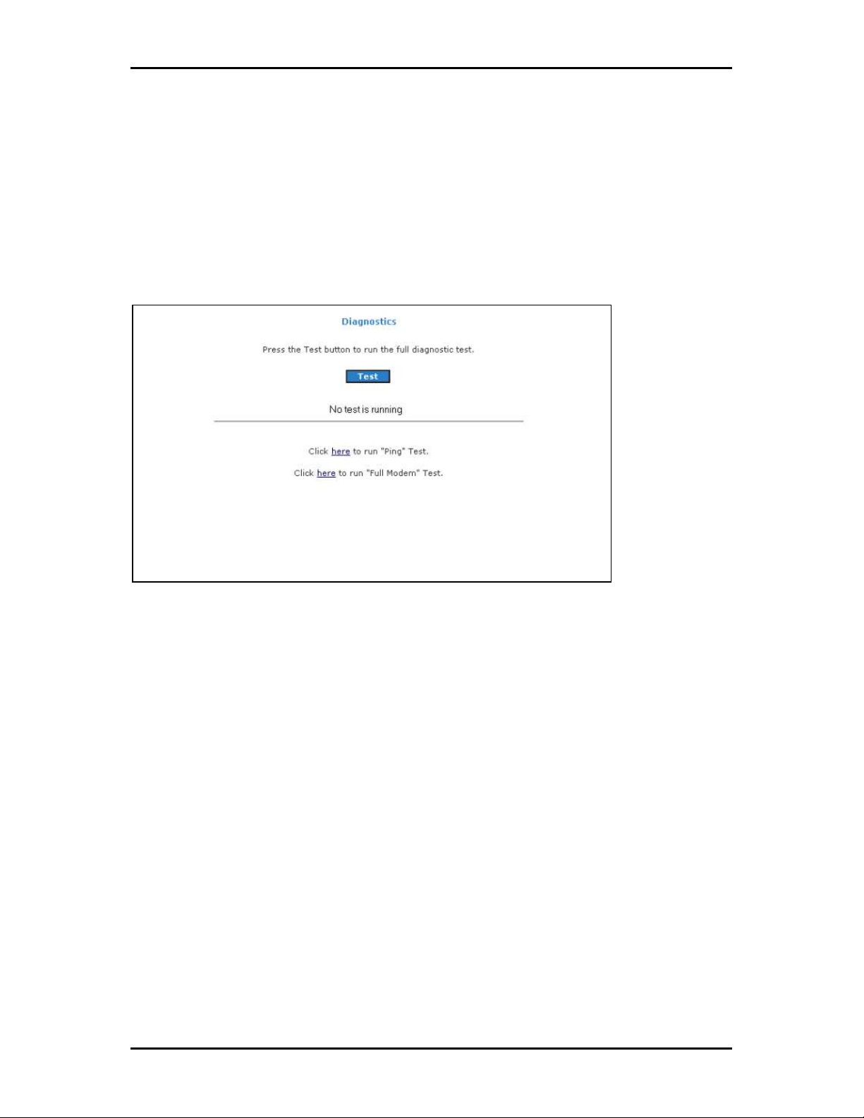
Diagnostics
Diagnostic Test is used for investigating whether the router is properly connected to the
WAN Network. This test may take a few seconds to complete. To perform the test, select
your connection from the list and press the Test button. Before running this test, make
sure you have a valid DSL link.
To run diagnostic test:
1. Select the Basic Menu
2. Click Test
failed, click Help
Basic Menu and then click Diagnostics
Basic Menu Basic Menu
Test. The test status will appear after running the diagnostic test. If a test
TestTest
Help to get the solution.
Help Help
Diagnostics. This opens the Diagnostics
DiagnosticsDiagnostics
Diagnostics page.
DiagnosticsDiagnostics
Page 24 of 90
Page 25

User Manual
Ping Test
Once you have your router configured, it is a good idea to make sure you can ping the
network. If you can ping an IP on the WAN side successfully, you should be able to surf
the Internet.
To perform a ping test:
1. Select the Basic
2. Click Ping Test
3. Change or leave the default settings of the following fields:
Enter the IP address to ping
Packet size
Number of echo request
4. Click Test
The ping results are displayed in the page. If the ping test was successful, it
means that the TCP/IP protocol is up and running. If the Ping test failed, you
should restart the router.
Basic Menu
Menu and then click Diagnostics
BasicBasic
Menu Menu
Ping Test. This opens the Ping Test
Ping TestPing Test
Test.
TestTest
Ping Test page.
Ping Test Ping Test
Diagnostics.
DiagnosticsDiagnostics
Full Modem Test
This test is used to check if your modem is properly connected to the network.
To perform a Full Modem test:
1. Select the Basic
2. Click Full Modem Test
Select your connection and then click Test
Basic Menu
Menu and then click Diagnostics
BasicBasic
Menu Menu
Full Modem Test. This opens the Modem Test
Full Modem TestFull Modem Test
Test.
TestTest
Diagnostics.
DiagnosticsDiagnostics
Modem Test page.
Modem Test Modem Test
Page 25 of 90
Page 26
User Manual
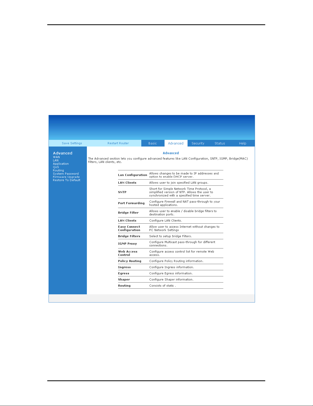
Advanced Menu
The Advanced mode provides advanced configuration settings for existing connections. At
least one WAN connection must be configured before implementing advanced WAN
configuration features. At least one LAN group must be defined before implementing
advanced LAN configuration features.
Advanced Menu
Advanced Menu
Advanced MenuAdvanced Menu
Page 26 of 90
Page 27

User Manual
WAN
Wide Area Network (WAN) is the source of your Internet connection.
New Connection
Your router can support up to eight different connections. If you have multiple virtual
connections, you may need to utilize the static routing capabilities of the modem to pass
data correctly.
There are five types of WAN connections:
PPPoE Connection
PPPoA Connection
Static Connection
DHCP Connection
Bridge Connection
Before you make a new WAN connection, you should make sure you have an existing
Internet connection.
Page 27 of 90
Page 28
User Manual
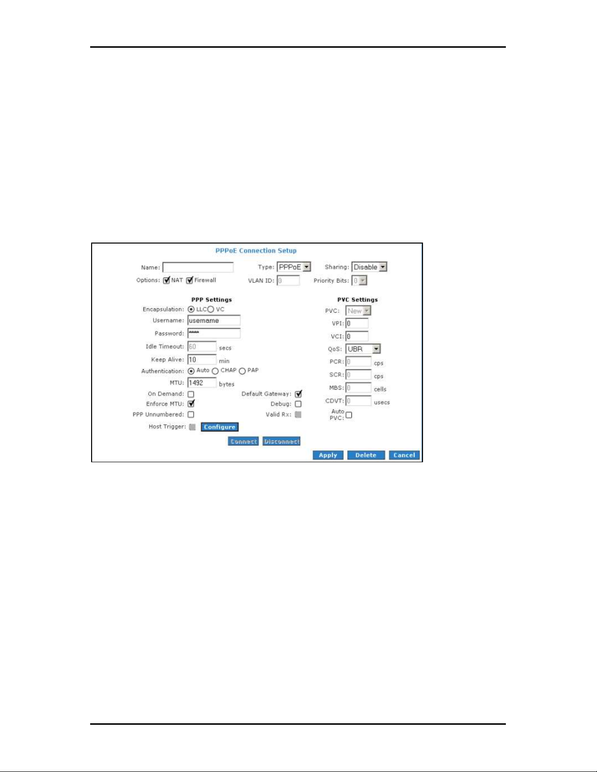
PPPoE Connection
PPP, or point-to-point protocol, is a method of establishing a network connection/session
between network hosts. PPPoE is a protocol for encapsulating PPP frames in Ethernet
frames and is described in RFC 2516. PPPoE provides the ability to connect to a network
of hosts over a simple bridging access device to a remote access concentrator. With this
model, each router uses its own PPP stack. Access control, billing, and type of service
control can all be done on a per-user rather than per-site basis.
New PPPoE Connection Setup
New PPPoE Connection Setup
New PPPoE Connection SetupNew PPPoE Connection Setup
Page 28 of 90
Page 29

User Manual
PPPoA Connection
PPPoA is also known as RFC 2364. It is a method of encapsulating PPP packets in ATM
cells that are carried over the DSL line. PPP, or point-to-point protocol, is a method of
establishing a network connection/session between network hosts. It usually provides a
mechanism of authenticating users. Logical link control (LLC) and virtual circuit (VC) are
two different methods of encapsulating the PPP packet. Contact your service provider to
determine which encapsulation is being used on your Internet connection.
New PPPoA Connection Setup
New PPPoA Connection Setup
New PPPoA Connection SetupNew PPPoA Connection Setup
Page 29 of 90
Page 30

User Manual
Static Connection
Static connection type is used whenever a known static IP address is assigned to the
router. Additional addressing information such as the subnet mask and the default
gateway must also be specified. Up to three Domain Name Server (DNS) addresses can
be identified. These servers resolve the name of the computer to the IP address mapped
to it and thus enable you to access other web servers by typing the symbolic name (host
name).
New Static Connection Setup
New Static Connection Setup
New Static Connection SetupNew Static Connection Setup
Page 30 of 90
Page 31

User Manual
DHCP Connection
DHCP allows the router to automatically obtain the IP address from the server. This option
is commonly used in when the IP is dynamically assigned and is not known prior to
assignment.
New DHCP Connection Setup
New DHCP Connection Setup
New DHCP Connection SetupNew DHCP Connection Setup
Page 31 of 90
Page 32

User Manual
Bridged Connection Setup
A pure bridged connection does not assign any IP address to the WAN interface. NAT and
firewall rules are not enabled. This connection method makes the router act as a bridge
for passing packets between the WAN interface and the LAN interface.
New Bridge Connection Setup
New Bridge Connection Setup
New Bridge Connection SetupNew Bridge Connection Setup
Page 32 of 90
Page 33

User Manual
ADSL Modulation
ADSL Modulation allows you to select any combination of DSL training modes. Leave the
default value if you are unsure or the service provider did not provide this information. In
most cases, this screen should not be modified.
ADSL Modulation
ADSL Modulation
ADSL ModulationADSL Modulation
Page 33 of 90
Page 34

User Manual
Connection Scan
This feature helps users to detect the PVC settings provided by the service provider.
Before the router can begin scanning the connection, the telephone line has to be
plugged into the router.
Connection Scan
Connection Scan
Connection ScanConnection Scan
To perform connections scan:
1. Select the Advanced Menu
2. Select WAN > Connection Scan
3. Click Scan
Advanced Menu.
Advanced MenuAdvanced Menu
WAN > Connection Scan.
WAN > Connection ScanWAN > Connection Scan
Scan.
ScanScan
Page 34 of 90
Page 35

User Manual
LAN
The router is preconfigured to automatically provide IP addresses to all the computers in
the Local Area Network (LAN). Your router allows you to create and configure LAN
groups.
LAN Configuration
The router can support up to two LAN groups through different physical interfaces. These
interfaces include:
Ethernet
USB
You can use other LAN interfaces to a group except for the Ethernet interface, which is
assigned to LAN group 1. Each LAN group can then be configured with static IP address,
dynamic IP address, or be unmanaged (no IP).
LAN Configuration
LAN Configuration
LAN ConfigurationLAN Configuration
Page 35 of 90
Page 36

User Manual
To configure the LAN groupings:
1. Select the Advanced Me
2. Select LAN > LAN Configuration
3. Select USB
Advanced Menu
Advanced MeAdvanced Me
LAN > LAN Configuration.
LAN > LAN ConfigurationLAN > LAN Configuration
USB in LAN group 1
USBUSB
LAN group 1 and then click < Remove
LAN group 1 LAN group 1
nu.
nunu
< Remove. No packets will be sent to the
< Remove< Remove
USB interface because it does not belong to any LAN group.
4. Select USB
LAN group 1, Configure
USB from Interfaces
USB USB
Interfaces and then click Add >
Interfaces Interfaces
Configure will appear in LAN group 2
Configure Configure
Add > under LAN group 2
Add > Add >
LAN group 2 to allow the definition of
LAN group 2 LAN group 2
LAN group 2. Just like in
LAN group 2LAN group 2
additional configurations.
5. To temporarily activate the settings, click Apply
6. To make changes permanent, click Save Settings
Note:
Note: You can configure the USB interface to a different LAN group except for the Ethernet interface,
Note:Note:
which cannot be moved from LAN group 1.
Save Settings.
Save SettingsSave Settings
Apply.
ApplyApply
Page 36 of 90
Page 37

User Manual
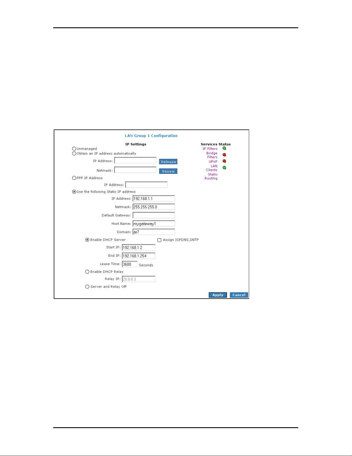
LAN Group Configuration
LAN Group Configuration allows you to configure settings for each LAN group. Notice that
you can also view the status of advanced services that can be applied to a LAN group.
Green indicates that the service is enabled, while red indicates that the service is
disabled.
LAN Group Configuration
LAN Group Configuration
LAN Group ConfigurationLAN Group Configuration
Category
Category Field
CategoryCategory
Unmanaged Unmanaged is a state when the LAN group is not
Obtain an IP address
automatically
IP Address You can retrieve/renew an IP address from the DHCP
Netmask The subnet mask of your router.
Field Description
FieldField
When this function is enabled, your router acts like a
Description
DescriptionDescription
configured and no IP address has been assigned to the
bridge.
client and requests an IP address from the DHCP server
on the LAN side.
server using the Release and Renew buttons.
Page 37 of 90
Page 38

User Manual
PPP IP Address Enables/disables PPP unnumbered feature.
IP Address The IP address should be different but within the same
subnet as the WAN-side IP address.
Use the following Static IP
address
This field enables you to change the IP address of the
router.
IP Address The default IP address of the router (as shown) is
192.168.1.1.
Netmask The default subnet mask of your router is 255.255.255.0.
This subnet allows the router to support 254 users. If you
want to support a larger number of users you can
change the subnet mask.
Default Gateway The default gateway is the routing device used to
forward all traffic that is not addressed to a station
within the local subnet. Your ISP provides you with the
IP address of the default gateway.
Host Name The host name is used in conjunction with the domain
name to uniquely identify the router. It can be any
alphanumeric word that does not contain spaces.
Domain The domain name is used in conjunction with the host
name to uniquely identify the router. To access the web
pages of the router you can type 192.168.1.1 (the IP
address) or mygateway1.ar7 (Host Name.Domain).
Enable DHCP Server Enables/disables DHCP. By default, your router has the
DHCP server (LAN side) enabled. If you already have a
DHCP server running on your network, you must disable
one of the two DHCP servers.
Assign ISP DNS,
SNTP
Enable/disables the Assign ISP DNS, SNTP feature when
the DHCP server of your router has been enabled. To
learn more, please refer to Assign ISP DNS, SNTP.
Start IP The Start IP Address is where the DHCP server starts
issuing IP addresses. This value must be greater than the
IP address value of the router. For example, if the IP
address of the router is 192.168.1.1 (default), then the
starting IP address must be 192.168.1.2 (or higher).
Note:
Note: If you change the start or end values, make sure
Note:Note:
the values are still within the same subnet as the router.
In other words, if the IP address of the router is
192.168.1.1 (default) and you change the DHCP
start/end IP addresses to be
192.168.1.2/192.168.1.100, you cannot communicate
Page 38 of 90
Page 39

with the router if your host has DHCP enabled.
End IP The End IP Address is where the DHCP server stops
issuing IP addresses. The ending address cannot exceed
a subnet limit of 254; hence the max value for the
default gateway is 192.168.1.254. If the DHCP server
runs out of DHCP addresses, users do not get access to
network resources. If this happens, you can increase the
Ending IP address (to the limit of 254) or reduce the
lease time.
Note:
Note: If you change the start or end values, make sure
Note:Note:
the values are still within the same subnet as the IP
address of the router. In other words, if the IP address of
the router is 192.168.1.1 (default) and you change the
DHCP start/end IP addresses to be
192.168.1.2/192.168.1.100, you cannot communicate
with the router if your host has DHCP enabled.
User Manual
Lease Time The Lease Time is the amount of time that a network
user is allowed to maintain a network connection to the
router using the current dynamic IP address. At the end
of the Lease Time, the lease is either renewed or the
DHCP server issues a new IP. The amount of time is in
units of seconds. The default value is 3600 seconds (1
hour). The maximum value is 999999 seconds
(About 278 hours).
Enable DHCP Relay In addition to the DHCP server feature, the router
supports the DHCP relay function. When the router is
configured as DHCP server, it assigns the IP addresses to
the LAN clients. When the gateway is configured as
DHCP relay, it is responsible for forwarding the requests
and responses negotiated between the DHCP clients and
the server.
Relay IP The IP address of the DHCP relay server.
Server and Relay Off When the DHCP server and relay functions are turned
off, the network administrator must carefully configure
the IP address, Subnet Mask, and DNS settings of every
host on your network. Do not assign the same IP address
to more than one host. Also, your router must reside on
the same subnet as all the other hosts.
Page 39 of 90
Page 40

User Manual
Assign ISP DNS, SNTP
When you enable the DHCP server, the router dynamically assigns IP addresses to
computers in the local network. The router provides its own LAN IP address (192.168.1.1)
as both the gateway and the DNS server.
The router has a choice of advertising its own IP address (192.168.1.1) as the DNS server
or providing the DNS that was received from the WAN. This can be configured by
enabling/disabling Assign ISP DNS SNTP
Note:
Note: ISP DNS, SNTP only applies when the DHCP server is enabled on the LAN Group Configuration
Note:Note:
page.
Assign ISP DNS SNTP on the LAN Group Configuration
Assign ISP DNS SNTP Assign ISP DNS SNTP
LAN Group Configuration page.
LAN Group Configuration LAN Group Configuration
LAN Clients
LAN Clients allows you to view and add computers in a LAN group. Each computer either
has a dynamic or static (manually-configured) IP address.
You can add a static IP address (belonging to the router’s LAN subnet) using the LAN
Clients page. Any existing static entry falling within the DHCP server's range can be
deleted.
LAN
LAN Clients
Clients
LAN LAN
ClientsClients
Page 40 of 90
Page 41

To add LAN Clients:
User Manual
1. Select Advanced Menu
2. Select LAN > LAN Clients
3. Select a LAN Connection
4. Click Apply
5. You can convert the dynamic into a static entry by clicking Reserve
Apply
Apply.
ApplyApply
6. To temporarily implement the settings, click Apply
7. To make changes permanent, click Save Settings
Advanced Menu.
Advanced MenuAdvanced Menu
LAN > LAN Clients. This opens the LAN Clients
LAN > LAN ClientsLAN > LAN Clients
LAN Connection, and enter IP Address
LAN ConnectionLAN Connection
Apply.
ApplyApply
LAN Clients page.
LAN Clients LAN Clients
IP Address, Hostname
IP AddressIP Address
Save Settings.
Save SettingsSave Settings
Hostname, and MAC Address
HostnameHostname
Apply.
ApplyApply
MAC Address.
MAC AddressMAC Address
Reserve, and then click
ReserveReserve
Page 41 of 90
Page 42

User Manual
Applications
Applications include:
Universal Plug and Play (UPnP)
Simple Network Timing Protocol (SNTP)
Internet Group Management Protocol (IGMP) Proxy
TR-068 WAN Access
DNS Proxy
Dynamic DNS Client
Port Forwarding
Bridge Filters
Web Access Control
Page 42 of 90
Page 43

User Manual
Universal Plug and Play
Universal plug and play (UPnP), NAT, and firewall traversal allow traffic to pass through
the router for applications using the UPnP protocol. This feature requires one active WAN
connection. In addition, the computer should support this feature. In the presence of
multiple WAN connections, select a connection on which the incoming traffic is present,
for example, the default WAN connection.
UPnP
UPnP
UPnPUPnP
To configure UPnP:
1. Select Advanced
2. Select Application > UPnP
3. Select the WAN Connection
Advanced.
AdvancedAdvanced
Application > UPnP.
Application > UPnPApplication > UPnP
WAN Connection and LAN Connection
WAN Connection WAN Connection
LAN Connection that will use UPnP from the drop-
LAN Connection LAN Connection
down lists.
4. Click Apply
5. To make changes permanent, click Save Settings
Apply to temporarily apply the settings.
Apply Apply
Save Settings.
Save SettingsSave Settings
Page 43 of 90
Page 44

User Manual
Simple Network Timing Protocol
Simple network timing protocol (SNTP) is a protocol used to synchronize the system time
to the public SNTP servers. It uses the UDP protocol on port 123 to communicate between
clients and servers.
SNTP
SNTP
SNTPSNTP
To enable SNTP:
1. Check Enable SNTP
Enable SNTP.
Enable SNTPEnable SNTP
2. Configure the following fields:
Primary SNTP Server
Primary SNTP Server The IP address or the host name of the primary SNTP
Primary SNTP Server Primary SNTP Server
server. This can be provided by ISP or defined by user.
Secondary SNTP Server
Secondary SNTP Server The IP address or the host name of the secondary
Secondary SNTP Server Secondary SNTP Server
SNTP server. This can be provided by ISP or defined by user.
Tertiary SNTP Server
Tertiary SNTP Server The IP address or the host name of the tertiary SNTP
Tertiary SNTP Server Tertiary SNTP Server
server. This can be provided by ISP or defined by user.
Timeout
Timeout If the router failed to connect to an SNTP server within the
Timeout Timeout
Timeout period, it retries the connection.
Page 44 of 90
Page 45

User Manual
Polling Interval
Polling Interval The amount of time between a successful connection with
Polling Interval Polling Interval
a SNTP server and a new attempt to connect to an SNTP server.
Retry Count
Retry Count The number of times the router tries to connect to an SNTP
Retry Count Retry Count
server before it tries to connect to the next server in line.
Time Zone
Time Zone The time zone in which the router resides.
Time Zone Time Zone
Day Light
Day Light Select this option to enable/disable daylight saving time (DST).
Day Light Day Light
DST is not automatically enabled or disabled. You need to manually enable
and disable it.
3. Click Apply
4. To make changes permanent, click Save Settings
Apply to temporarily apply the settings.
Apply Apply
Save Settings.
Save SettingsSave Settings
Page 45 of 90
Page 46

User Manual
IGMP Proxy
IP hosts use Internet group management protocol (IGMP) to report their multicast group
memberships to neighboring routers. Similarly, multicast routers use IGMP to discover
which of their hosts belong to multicast groups. Your router supports IGMP proxy that
handles IGMP messages. When enabled, your router acts as a proxy for a LAN host
making requests to join and leave multicast groups, or a multicast router sending
multicast packets to multicast groups on the WAN side.
IGMP Proxy
IGMP Proxy
IGMP ProxyIGMP Proxy
Multicasting is a form of limited broadcast. UDP is used to send datagrams to all hosts
that belong to what is called a Host Group. A host group is a set of one or more hosts
identified by a single IP destination address. The following statements apply to host
groups:
Anyone can join or leave a host group at will.
There are no restrictions on a host’s location.
There are no restrictions on the number of members that may belong to a host
group.
A host may belong to multiple host groups.
Page 46 of 90
Page 47

User Manual
Non-group members may send UDP datagrams to the host group.
Multicasting is useful when the same data needs to be sent to more than one device. For
instance, if one device is responsible for acquiring data that many other devices need,
then multicasting is a natural fit. Note that using multicasting as opposed to sending the
same data to individual devices uses less network bandwidth. The multicast feature also
enables you to receive multicast video streams from multicast servers.
The IGMP Proxy page allows you to enable multicast on available WAN and LAN
connections. You can configure the WAN or LAN interface as one of the following:
Upstream
Upstream The interface that IGMP requests from hosts are sent to the multicast
UpstreamUpstream
router.
Downstream
Downstream The interface data from the multicast router are sent to hosts in the
DownstreamDownstream
multicast group database.
Ignore
Ignore No IGMP request nor data multicast are forwarded.
IgnoreIgnore
You can perform one of the two options:
1. Configure one or more WAN interface as the upstream interface.
2. Configure one or more LAN interface as the upstream interface.
To configure the IGMP Proxy:
1. Select Advanced
2. Select Application > IGMP Proxy
Advanced.
AdvancedAdvanced
Application > IGMP Proxy.
Application > IGMP ProxyApplication > IGMP Proxy
3. Configure the following interfaces:
Quickstart
LAN group 1
4. Click Apply
5. To make changes permanent, click Save Settings
Apply to temporarily apply the settings.
ApplyApply
Save Settings.
Save SettingsSave Settings
Page 47 of 90
Page 48

User Manual
TR-068 WAN Access
The TR-068 WAN Access page enables you to give temporary permission to someone
(such as technical support staff) to be able to access your router from the WAN side.
From the moment the account is enabled the user is expected to log in within 20
minutes, otherwise the account expires. Once the user has logged in, if the session
remains inactive for more than 20 minutes, the user will be logged out and the account
expires.
Enable WAN Access Update
Enable WAN Access Update
Enable WAN Access UpdateEnable WAN Access Update
To create a temporary user account for remote access:
1. Select the Advanced Menu
2. Select Application > TR
3. Select WAN Update
4. Select WAN Access
5. Enter a user name and password in the User Name
Advanced Menu.
Advanced MenuAdvanced Menu
Application > TR----068 WAN Access
Application > TRApplication > TR
WAN Update.
WAN UpdateWAN Update
WAN Access.
WAN AccessWAN Access
068 WAN Access.
068 WAN Access068 WAN Access
User Name and Password
User Name User Name
6. Enter a port number In the Port field (for example, 51003).
To access your router remotely, enter the following URL:
http(s)://10.10.10.5:51003
Password fields.
Password Password
Page 48 of 90
Page 49
User Manual
Syntax
Syntax: http(s)://WAN IP of router:Port Number
SyntaxSyntax
7. Click Apply
8. To make changes permanent, click Save Settings
Apply to temporarily apply the settings.
Apply Apply
Save Settings.
Save SettingsSave Settings
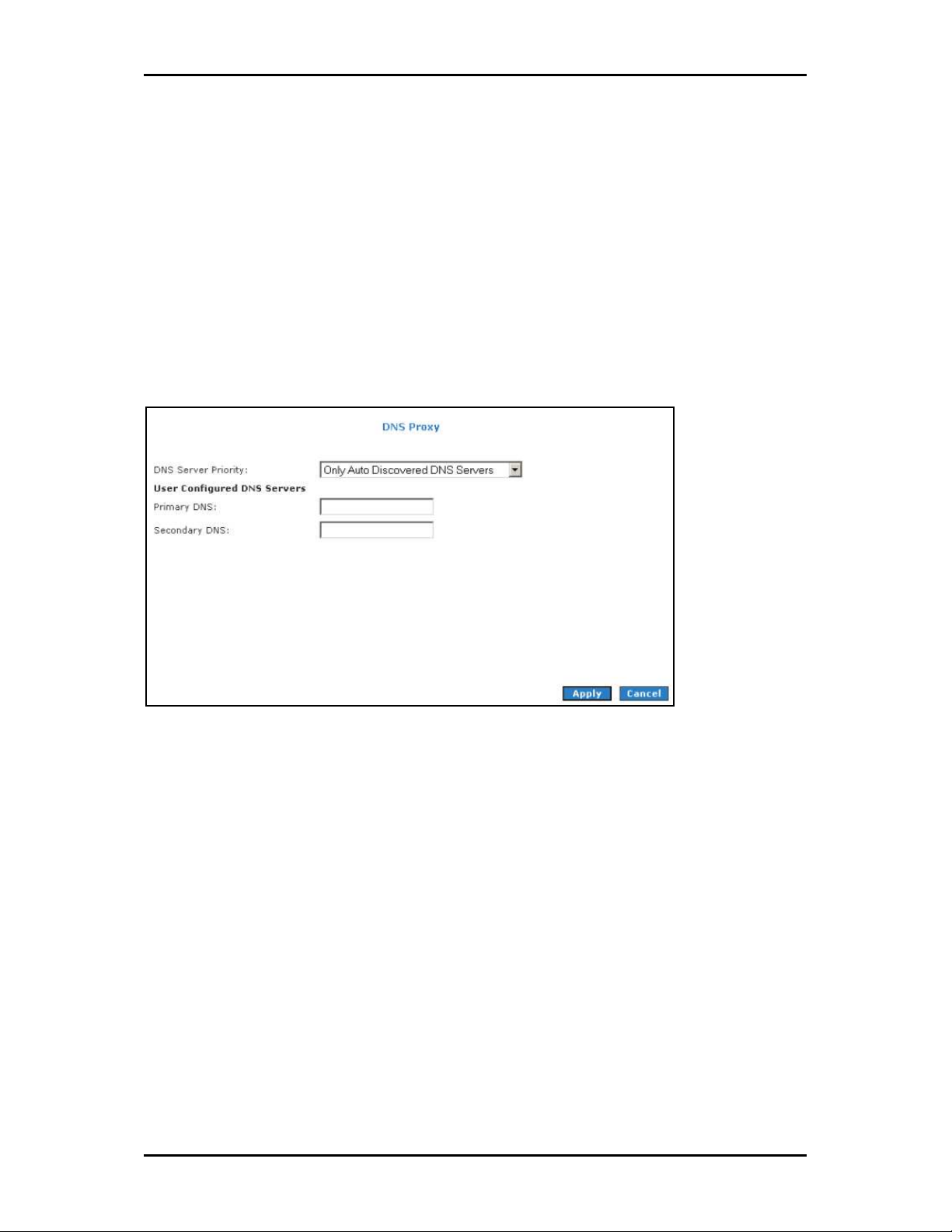
DNS Proxy
This feature allows the user to select the Domain Name Server (DNS) Server Priority as
well as enter IP addresses for primary DNS and secondary DNS.
DNS Proxy
DNS Proxy
DNS ProxyDNS Proxy
To select the DNS Server Priority:
1. Select Advanced
2. Select Application > DNS Proxy
Advanced.
AdvancedAdvanced
Application > DNS Proxy.
Application > DNS ProxyApplication > DNS Proxy
3. Select the DNS Server Priority.
Only Auto Discovered DNS Servers
Only User Configured DNS Servers
Auto Discovered then User Configured
User Configured then Auto Discovered
Page 49 of 90
Page 50

User Manual
4. Click Apply
5. To make changes permanent, click Save Settings
Apply to temporarily apply settings.
Apply Apply
Save Settings.
Save SettingsSave Settings
Dynamic DNS Client
Dynamic DNS allows the user to register with a Dynamic DNS Provider. The Dynamic DNS
will be linked with the WAN IP of the router even after the ISP update the WAN IP to
another IP address. It can be useful in web hosting and FTP services.
Dynamic DNS Client
Dynamic DNS Client
Dynamic DNS ClientDynamic DNS Client
Note:
Note: The User Name/Password entered should be similar to the User Name/Password you have
Note:Note:
specified during the registration of the DNS hostname.
To enable Dynamic DNS:
1. Select Advanced
2. Select Application > Dynamic DNS Client
Advanced.
AdvancedAdvanced
Application > Dynamic DNS Client.
Application > Dynamic DNS ClientApplication > Dynamic DNS Client
3. Configure the following fields:
Connection
DDNS Server
DDNS Client
Page 50 of 90
Page 51

User Manual
User Name
Password
Domain Name
4. Click Apply
5. To make changes permanent, click Save Settings
Apply to temporarily apply the settings.
Apply Apply
Settings.
SettingsSettings
Port Forwarding
Port forwarding (or virtual server) allows you to direct incoming traffic to specific LAN
hosts based on a protocol port number and protocol. Using the Port Forwarding page, you
can provide local services (for example, web hosting) for people on the Internet or play
Internet games. Port forwarding is configurable per LAN group.
Port Forwarding
Port Forwarding
Port ForwardingPort Forwarding
A database of predefined port forwarding rules allows you to apply one or more rules to
one or more members of a defined LAN group. You can view the rules associated with a
predefined category and add the available rules for a given category. You can also
create, edit, or delete your own port forwarding rules.
Page 51 of 90
Page 52

User Manual
To configure port forwarding:
1. Select Advanced
2. Select Application > Port
3. Select WAN Connection
available in the LAN IP
page
page, which is accessed by clicking New IP
pagepage
4. Select the available rules for a given category and click Add
this category. If a rule is not in the list, you can create your own rule in the User
category. Select User
5. The Rule Management page opens for you to create new rules. Enter Rule Name
Protocol
Protocol, Port
ProtocolProtocol
Advanced.
AdvancedAdvanced
Application > Port Forwarding
Application > PortApplication > Port
WAN Connection, LAN Group
WAN ConnectionWAN Connection
LAN IP drop-down menu, you can add it using the LAN Client
LAN IP LAN IP
User, and then click New
UserUser
Port Start
Start, Port End
PortPort
Start Start
Forwarding.
Forwarding Forwarding
LAN Group, and LAN IP
LAN GroupLAN Group
Port End, and Port Map
Port EndPort End
Port Map, and then click Apply
Port MapPort Map
New IP.
New IPNew IP
New.
NewNew
LAN IP. If the desired LAN IP is not
LAN IPLAN IP
LAN Client
LAN Client LAN Client
Add to apply the rule for
AddAdd
User
User User
Rule Name,
Rule NameRule Name
Apply.
ApplyApply
6. Continue to add rules as they apply from each category.
7. Click Apply
Apply to temporarily activate the settings.
Apply Apply
8. To make changes permanent, click Save Settings
Save Settings.
Save SettingsSave Settings
Page 52 of 90
Page 53

User Manual
DMZ Settings
Setting a host on your local network as demilitarized zone (DMZ) forwards any network
traffic that is not redirected to another host via the Port Forwarding feature to the IP
address of the host. This opens the access to the DMZ host from the Internet. This
function is disabled by default. By enabling DMZ, you add an extra layer of security
protection for hosts behind the firewall.
To enable DMZ Settings:
1. On the Port Forwarding
Port Forwarding page, select Enable DMZ
Port Forwarding Port Forwarding
Enable DMZ. This opens the DMZ Settings
Enable DMZEnable DMZ
page.
2. Select the WAN Connection
3. Click Apply
4. To make changes permanent, click Save Settings
WAN Connection, LAN Group
WAN ConnectionWAN Connection
Apply to temporarily apply the settings.
Apply Apply
LAN Group, and LAN IP Addres
LAN GroupLAN Group
Save Settings.
Save SettingsSave Settings
LAN IP Addresssss.
LAN IP AddresLAN IP Addres
Custom Port Forwarding
The Custom Port Forwarding page allows you to create up to 15 custom Port Forwarding
entries to support specific services or applications, such as concurrent NAT/NAPT
operation.
Page 53 of 90
Page 54

User Manual
Bridge Filters
The Bridge Filters allows you to enable, add, edit, or delete the filter rules. When bridge
filtering is enabled, each frame is examined against every defined filter rule in sequence.
When a match is found, the appropriate filtering action (allow or deny) is performed. Up
to 20 filter rules are supported with bridge filtering.
Bridge Filters
Bridge Filters
Bridge FiltersBridge Filters
To configure Bridge Filters:
1. Select Advanced
2. Select Application > Bridge Filters
3. Select Enable Bridge Filters
4. To add a rule, enter the source MAC address
Protocol
Protocol with desired filtering type, then click Add
Protocol Protocol
Note:
Note: You can also edit a rule that you created using the Edit
Note:Note:
Advanced.
AdvancedAdvanced
Application > Bridge Filters. This opens the Bridge Filters page.
Application > Bridge FiltersApplication > Bridge Filters
Enable Bridge Filters.
Enable Bridge FiltersEnable Bridge Filters
MAC address, Destination MAC addresses
MAC addressMAC address
5. Click Apply
6. To make changes permanent, click Save Settings
Apply to temporarily activate the settings.
Apply Apply
Save Settings.
Save SettingsSave Settings
Destination MAC addresses, and
Destination MAC addressesDestination MAC addresses
Add.
AddAdd
Edit checkbox. You can delete using Delete
Edit Edit
Delete.
DeleteDelete
Page 54 of 90
Page 55

User Manual
Web Access Control
The Web Access Control page allows you to access the router via the web from a remote
location like your home or office.
Web Access Control
Web Access Control
Web Access ControlWeb Access Control
To configure Web Access:
1. Select Advanced Menu
2. Select Application > Web Access Control
3. Select Enable
4. Select the connection used to connect to the Internet in the Choose a connection
Advanced Menu.
Advanced MenuAdvanced Menu
Application > Web Access Control.
Application > Web Access ControlApplication > Web Access Control
Enable.
EnableEnable
Choose a connection.
Choose a connectionChoose a connection
5. Configure the following fields:
Remote Host IP
Remote Netmask
Redirect Port
6. Click Apply
Apply to temporarily activate the settings on the page. The WAN address is
Apply Apply
now added into the IP Access List. This allows you to access you router remotely.
7. To make changes permanent, click Save Settings
Save Settings.
Save SettingsSave Settings
Page 55 of 90
Page 56

User Manual
Quality of Service
Quality of service allows network administrators to configure the routers to meet the real
time requirements for voice and video.
Different networks use different QoS markings like:
ToS network: ToS bits in the IP header
VLAN network: priority bits in the VLAN header
DSCP network: uses only 5 bits of the CoS
WLAN: WLAN QoS header.
The QoS framework is supported on all the above domains. How do you make them talk
to each other? How can you make sure the priority from one network is carried over to
another network? Class of service (CoS) is introduced as the common language for the
QoS mappings. When QoS is enabled, the router has full control over packets from the
time they enter the router till they leave the router. This is how it works: The domain
mapping (ToS bits, priority bits, etc.) of a packet needs to be translated to CoS when the
packet enter the router, and vice versa, the CoS of a packet needs to be translated back
to the domain mapping when the packet leaves the router.
There are some additional terms you should get familiarize with:
Ingress: Packets arriving into the router from a WAN/LAN interface.
Egress: Packets sent from the router to a WAN/LAN interface.
Trusted mode: Honors the domain mapping (ToS byte, WME, WLAN user priority).
Untrusted mode: Does not honor domain mapping. This is the default QoS setting.
Traffic Conditioning Agreement (TCA): The TCA needs to be defined for each
interface:
Page 56 of 90
Ingress mappings (Domain =>CoS)
o
Page 57

User Manual
o Egress Mappings (CoS => Domain)
o Untrusted mode (default)
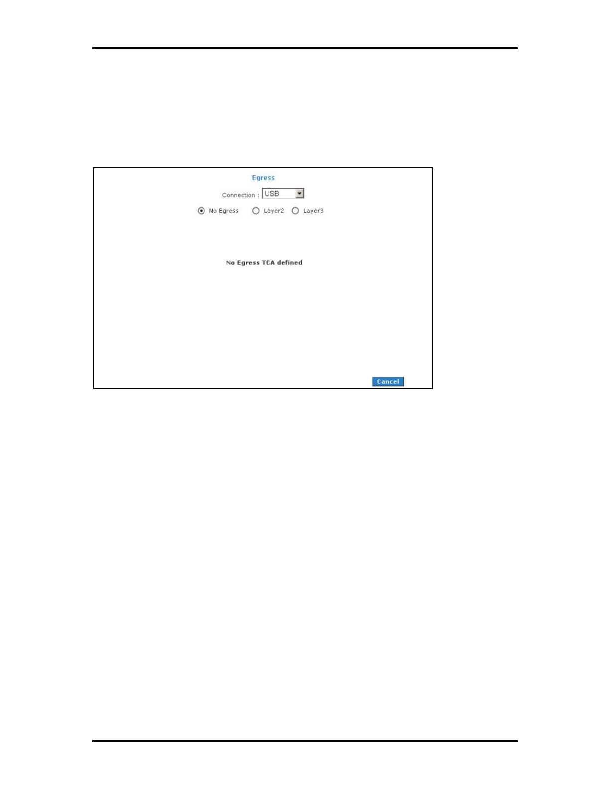
Shaper
Egress
For packets going out of the router, the markings (CoS) need to be translated to the
mappings understood by the network domains. The reverse CoS and domain mapping is
configured using the Egress. To access Egress
QoS > Egress
QoS > Egress.
QoS > EgressQoS > Egress
There are three Egress modes:
No Egress mode
Layer 2
Layer 3
Egress, select the Advanced Menu
EgressEgress
Advanced Menu and then select
Advanced Menu Advanced Menu
Page 57 of 90
Page 58
User Manual
No Egress Mode
The default Egress page setting for all interfaces is No Egress. In this mode, the domain
mappings of the packets are untouched.
Egress
Egress
EgressEgress
Page 58 of 90
Page 59

User Manual
Layer 2
The Egress Layer 2 page allows you to map the CoS of an outgoing packet to user priority
bits, which is honored by the VLAN network. Again, this feature is only configurable on
the WAN interfaces as VLAN is only supported on the WAN side in the current release.
Laye
Layer 2
r 2
LayeLaye
r 2r 2
Page 59 of 90
Page 60

User Manual
Layer 3
Egress Layer 3 enables you to map CoS to ToS so that the priority marking of outgoing
packets can be carried over to the IP network.
Layer 3
Layer 3
Layer 3Layer 3
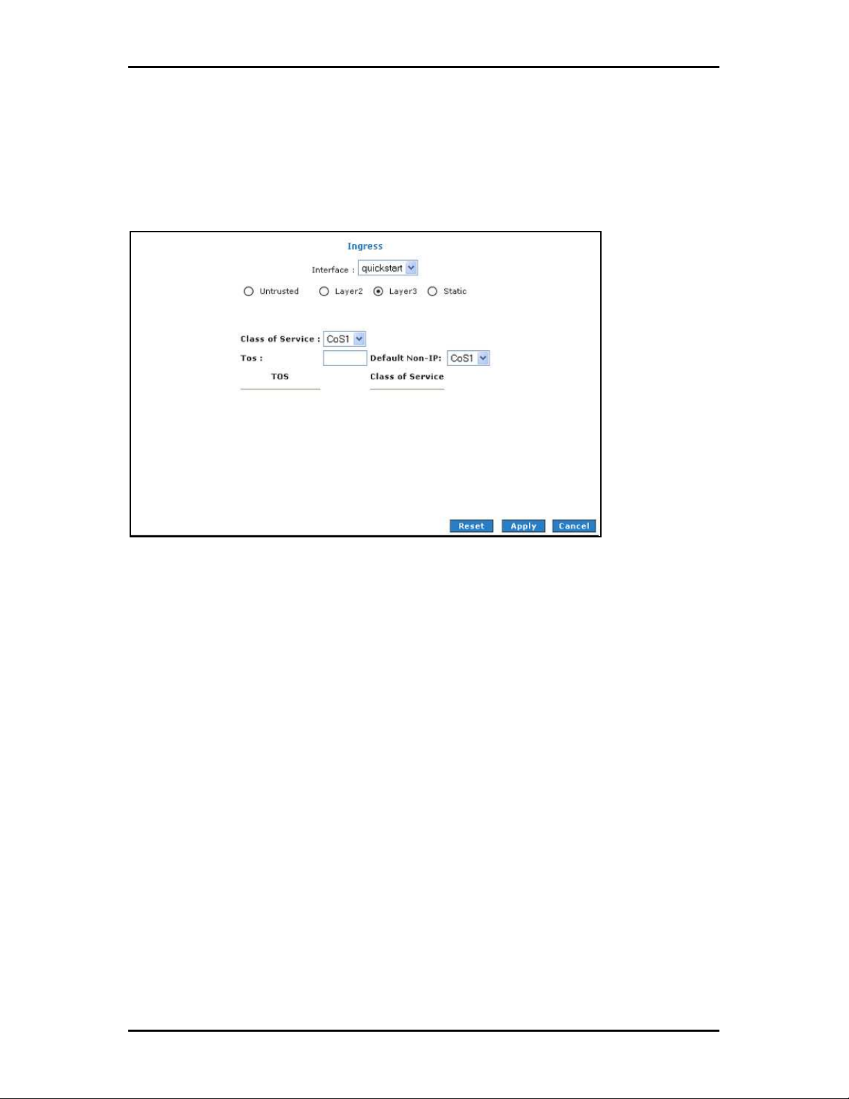
Ingress
Ingress enables you to configure QoS for packets as soon as they come into the router.
The domain mappings are converted to CoS (the common language) so that the priority
marking is carried over.
There are four Ingress modes:
Untrusted mode
Layer 2
Layer 3
Static
Page 60 of 90
Page 61

User Manual
Untrusted Mode
Untrusted is the default Ingress page setting for all interfaces. In this mode, no domain
mapping is honored in the router. All packets are treated as CoS6 (best effort).
Untrusted mode
Untrusted mode
Untrusted modeUntrusted mode
Page 61 of 90
Page 62

User Manual
Layer 2
Layer 2 allows you to map an incoming packet with VLAN priority to CoS. This feature is
only configurable on the WAN interfaces as VLAN is only supported on the WAN side in
the current software release.
Layer 2
Layer 2
Layer 2Layer 2
Page 62 of 90
Page 63
User Manual
Layer 3
The Layer 3 page allows you to map ToS bits of incoming packets from the IP network to
CoS for each WAN/LAN interface.
Layer 3
Layer 3
Layer 3Layer 3
Page 63 of 90
Page 64

User Manual
Static
The Ingress - Static page enables you to configure a static CoS for all packets received on
a WAN or LAN interface.
Static
Static
StaticStatic
Page 64 of 90
Page 65

User Manual
QoS Shaper Configuration
The Shaper Configuration page is accessed by selecting Shaper on the Advanced main
page. Three shaper algorithms are supported:
HTB
Low Latency Queue Discipline
PRIOWRR
QoS Shaper Configuration
QoS Shaper Configuration
QoS Shaper ConfigurationQoS Shaper Configuration
Note:
Note: Egress TCA is required if shaper is configured for that interface.
Note:Note:
Of the three shaping algorithms available on the Shaper Configuration page, only one can
be enabled at a time. An example of each configuration is given as follows.
Page 65 of 90
Page 66

User Manual
Example 1: HTB Queue Discipline Enabled
In the example below, HTB Queue Discipline is enabled. The PPPoE1 connection has a
total of 300 Kbps of bandwidth, of which 100 Kbps is given to CoS1 and another 100 Kbps
is given to CoS2. When there is no CoS1 or CoS2 packets, CoS6 packets have the whole
300 Kbps of bandwidth.
HTB Queue Discipline enabled
HTB Queue Discipline enabled
HTB Queue Discipline enabledHTB Queue Discipline enabled
Page 66 of 90
Page 67

User Manual
Example 2: Low Latency Queue Discipline Enabled
In this second example, Low Latency Queue Discipline is enabled. CoS1 is not rate
controlled (hence the field is disabled). CoS2 takes 100 Kbps when there is no CoS1
packet. CoS6 has 300 Kbps when there is no CoS1 or CoS2 packets. This is similar to the
HTB queue discipline as they are both rate-based algorithm, except that CoS1 is handled
differently.
Low Latency Queue Discipline enabled
Low Latency Queue Discipline enabled
Low Latency Queue Discipline enabledLow Latency Queue Discipline enabled
Page 67 of 90
Page 68

User Manual
Example 3: PRIOWRR Enabled
In this third example, PRIOWRR is enabled. Since PRIOWRR operates only on the number
of packets being transmitted, the max rate field has been disabled. Only percentage can
be assigned to the CoS2 - CoS6. CoS1 is not rate controlled (hence the field is not
displayed). When there is no CoS1 packet, CoS2, CoS3, CoS4 each has 10 percent, and
CoS6 has 70 percent. This is similarly to the Low Latency Queue discipline, except that
one is packet-based, and the other is rate-based.
PRIOWRR enabled
PRIOWRR enabled
PRIOWRR enabledPRIOWRR enabled
Page 68 of 90
Page 69

User Manual
Policy Routing Configuration
The Policy Routing Configuration page is accessed by selecting Policy Routing
Configuration on the Advanced home page under QoS. This page enables you to
configure policy routing and QoS. The policy routing configuration is discussed as follows.
The QoS configuration is discussed in ‘‘Ingress Payload Database Configuration’’.
Policy Routing Configuration
Policy Routing Configuration
Policy Routing ConfigurationPolicy Routing Configuration
Currently routing algorithms make decision based on destination address, i.e. only
Destination IP address and subnet mask is supported. The Policy Routing page enables
you to route packets on the basis of various fields in the packet. The following fields can
be configured for Policy Routing:
Destination IP address/mask
Source IP address/mask
Source MAC address
Protocol (TCP, UDP, ICMP, etc)
Source port
Page 69 of 90
Page 70

User Manual
Destination port
Incoming interface
DSCP
Page 70 of 90
Page 71

User Manual
Routing
Static Routing
If the ADSL Router is connected to more than one network, you may need to set up a
static route between them. A static route is a pre-defined pathway that network
information must travel to reach a specific host or network. You can use static routing to
allow different IP domain users to access the Internet through the ADSL Router.
Static Routing
Static Routing
Static RoutingStatic Routing
The New Destination IP is the address of the remote LAN network or host to which you
want to assign a static route. Enter the IP address of the host for which you wish to
create a static route here. For a standard Class C IP domain, the network address is the
first three fields of the New Destination IP, while the last field should be 0. The Subnet
Mask identifies which portion of an IP address is the network portion, and which portion
is the host portion. For a full Class C Subnet, the Subnet Mask is 255.255.255.0. The
Gateway IP address should be the IP address of the gateway device that allows for
contact between the Gateway and the remote network or host
Page 71 of 90
Page 72

User Manual
Routing Table
Routing Table displays the information used by routers when making packet forwarding
decisions. Packets are routed according to the packet's destination IP address.
Routing Table
Routing Table
Routing TableRouting Table
Page 72 of 90
Page 73

User Manual
System Password
Anyone who can access the web interface can be considered an Administrator. To restrict
access to the web interface, you need to set the System Password.
To change the System Password:
1. Select Advanced Menu
2. Click System Password
3. Select Enable Authentication
Advanced Menu
Advanced MenuAdvanced Menu
System Password. This opens the System Password
System Password System Password
Enable Authentication.
Enable AuthenticationEnable Authentication
System Password page.
System PasswordSystem Password
4. Enter your password.
5. Reenter your password in the Confirm Password
6. To temporarily implement the settings, click Apply
7. To make changes permanent, click Save Settings
Note:
Note: Remember your account information. If you forget the User Name and System Password, you
Note:Note:
will need to reset the router to its default settings. To reset, press RESET
panel for 10 seconds.
To change the timeout settings:
Confirm Password text box.
Confirm Password Confirm Password
Apply.
ApplyApply
Save Settings.
Save SettingsSave Settings
RESET at the router’s back
RESET RESET
1. Select Advanced Menu
2. Click System Password
3. Select Enable Authentication
4. Enter the number of minutes in the Idle Timeout
5. To temporarily implement the settings, click Apply
6. To make changes permanent, click Save Settings
Advanced Menu
Advanced MenuAdvanced Menu
System Password.
System PasswordSystem Password
Enable Authentication.
Enable AuthenticationEnable Authentication
Idle Timeout text field.
Idle Timeout Idle Timeout
Apply.
ApplyApply
Save Settings.
Save SettingsSave Settings
Page 73 of 90
Page 74

User Manual
Firmware Update
When updating the firmware, make sure you are using the correct file. Once the upgrade
is complete the router will reboot. You will need to log back into the router after the
firmware upgrade is completed.
To update the firmware:
1. Select the Advanced Menu
Firmware Upgrade
Firmware Upgrade page.
Firmware UpgradeFirmware Upgrade
2. Click Browse
3. Click Update Gateway
Browse and then locate the firmware file.
BrowseBrowse
Update Gateway. The update may take a few minutes. Make sure that the
Update GatewayUpdate Gateway
power is not turned off during the update process.
Advanced Menu and then click Firmware Upgrade
Advanced Menu Advanced Menu
Firmware Upgrade. This opens the
Firmware UpgradeFirmware Upgrade
Restore to Default
To reset to the default factory settings, press RESET
the router’s back panel. When you reset, all the firmware updates will be lost.
To access the web interface again, you need to install the router anew.
RESET for 10 seconds. This can be found at
RESETRESET
Page 74 of 90
Page 75

User Manual
Security Menu
Security Menu allows you to configure security tools like IP Filters and LAN Isolation.
Security Menu
Security Menu
Security MenuSecurity Menu
Page 75 of 90
Page 76
User Manual
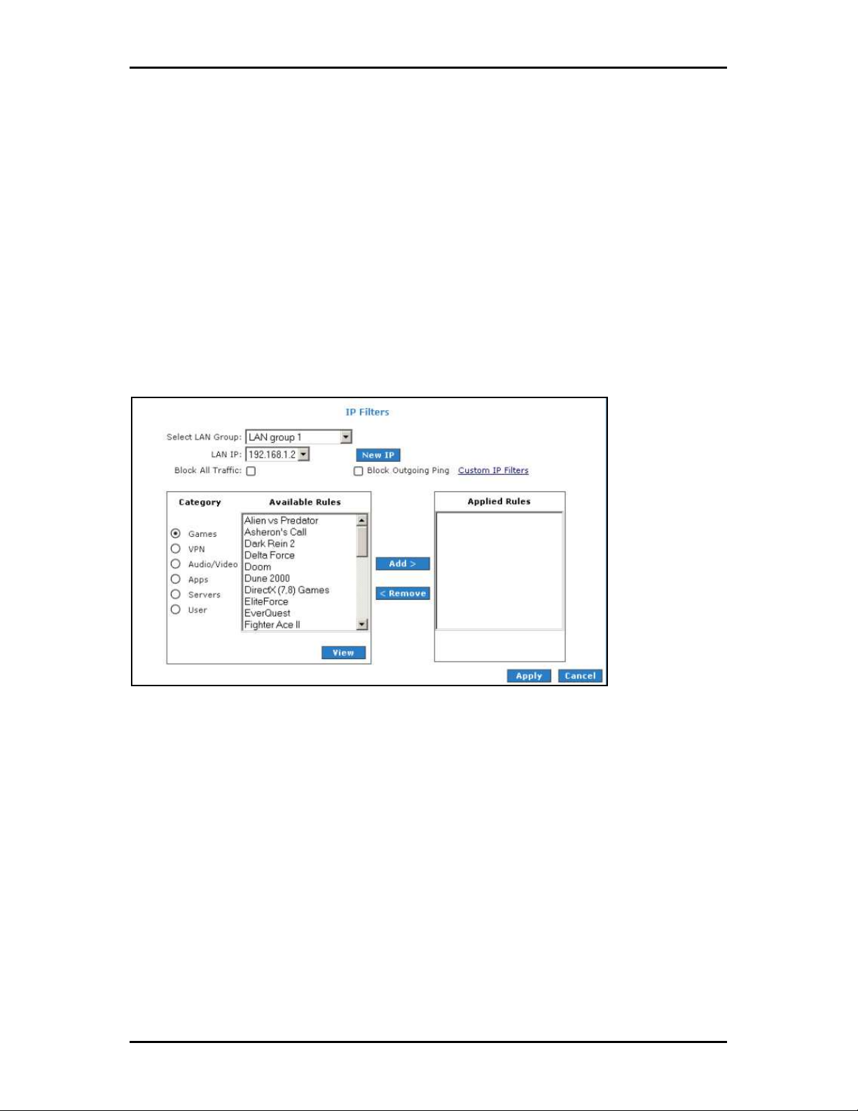
IP Filters
IP filtering allows you to block specific applications/services based on the IP address of
the LAN device. In this page, you can block specific traffic (for example, block web
access) or any traffic from a host on your local network.
A database of predefined IP filters allows you to apply one or more filtering rules to one
or more members of a defined LAN group. You can view the rules associated with a
predefined filter and add the available rules for a given category. You can also create,
edit, or delete your own IP filter rules.
IP Filters
IP Filters
IP FiltersIP Filters
To configure IP Filters:
1. Select the Security Menu
2. On the IP Filters
Security Menu and then click IP Filters
Security Menu Security Menu
IP Filters page, select LAN Group
IP Filters IP Filters
LAN Group and LAN IP
LAN Group LAN Group
IP Filters.
IP FiltersIP Filters
LAN IP. If the desired LAN IP is not
LAN IPLAN IP
available in the LAN IP drop-down menu, you can add it using the LAN Client
page, which is accessed by clicking New IP
3. Select the available rules for a given category. Click View
associated with a predefined filter. Click Add
New IP.
New IPNew IP
View to view the rule
View View
Add to apply the rule for this category.
Add Add
4. If a rule is not in the list, you can create your own rule in the User ca
User
User, and then click New
UserUser
Page 76 of 90
New.
NewNew
LAN Client
LAN Client LAN Client
User category
User caUser ca
tegory. Select
tegorytegory
Page 77

User Manual
5. The Rule Management page opens for you to create new rules. Enter Rule Name
Protocol
Protocol, Port Start
ProtocolProtocol
The rules you create will appear in the Available Rules
Port Start, Port End
Port StartPort Start
Port End, and Port Map
Port EndPort End
Port Map, and then click Apply
Port MapPort Map
Available Rules pane in the User category.
Available RulesAvailable Rules
Apply.
ApplyApply
Rule Name,
Rule NameRule Name
You can view or delete the rules you create.
6. Continue to add rules as they apply from each category using the Add
7. To temporarily implement the changes, click Apply
8. To make the change permanent, click Save Settings
Save Settings.
Save SettingsSave Settings
Apply.
ApplyApply
Add button.
Add Add
Page 77 of 90
Page 78

User Manual
LAN Isolation
LAN isolation allows you to disable the flow of packets between two LAN groups. This
allows you to secure information in private portions of the LAN from other publicly
accessible LAN segments.
LAN Isolation
LAN Isolation
LAN IsolationLAN Isolation
To enable LAN Isolation:
1. Select the Security Menu
2. On the LAN Isolation
group 1 and LAN group 2
group 1 and LAN group 2.
group 1 and LAN group 2group 1 and LAN group 2
Security Menu and then click LAN Isolation
Security MenuSecurity Menu
LAN Isolation page, select the checkbox for Disable traffic between LAN
LAN Isolation LAN Isolation
LAN Isolation.
LAN IsolationLAN Isolation
3. To temporarily implement the changes, click Apply
4. To make changes permanent, click Save Settings
Save Settings.
Save SettingsSave Settings
Apply.
ApplyApply
Disable traffic between LAN
Disable traffic between LAN Disable traffic between LAN
Page 78 of 90
Page 79

Status Menu
The Status Menu provides the status for different connections or interfaces.
User Manual
Status Menu
Status Menu
Status MenuStatus Menu
Your router allows you to view the following status and product information:
Connection Status
System Log
Remote Log
Network Statistics
DDNS Update Status
DHCP Clients
QoS Status
Page 79 of 90
Page 80

User Manual
Modem Status
Product Information
Connection Status
Connection Status displays the type of protocol, the WAN IP address, the connection state
and the duration of your Internet connection.
Connection Status
Connection Status
Connection StatusConnection Status
To view the Connection Status, select the Status Menu
Status Menu and then click Connection Status
Status Menu Status Menu
Connection Status.
Connection StatusConnection Status
Page 80 of 90
Page 81

User Manual
System Log
System Log displays the router log. Depending on the severity level, the information log
will generate log reports to a remote host if remote logging is enabled.
System Log
System Log
System LogSystem Log
To view the System Log, select the Status Menu
Status Menu and then click System Log
Status Menu Status Menu
System Log.
System LogSystem Log
Page 81 of 90
Page 82

User Manual
Remote Log
Remote Log allows you to forward all logged information to one (or more) remote
computer. The type of information forwarded to the remote computer depends on the
Log level. Each log message belongs to a certain log level, which indicates the severity of
the event.
When you configure remote logging, you must specify a severity level. Log messages
that are rated at that level or higher are sent to the log server and can be viewed using
the server log application, which can be downloaded from the web.
Remote Log Settings
Remote Log Settings
Remote Log SettingsRemote Log Settings
To enable remote logging:
1. Select the Status Menu
2. Select a Log Level
Panic
Panic System panic or other condition that causes the router to stop
Panic Panic
Status Menu and then click Remote Log
Status Menu Status Menu
Log Level. There are 8 log levels listed below in order of severity.
Log LevelLog Level
functioning....
Alert
Alert Conditions that require immediate correction, such as a corrupted system
Alert Alert
database.
Critical
Critical Critical conditions such as hard drive errors.
Critical Critical
Page 82 of 90
Remote Log.
Remote LogRemote Log
Page 83

User Manual
Error
Error Error conditions that generally have less serious consequences than
Error Error
errors in the emergency, alert, and critical levels....
Warning
Warning Conditions that warrant monitoring.
Warning Warning
Notice
Notice (Default) Conditions that are not errors but might warrant special
Notice Notice
handling.
Info
Info Events or non-error conditions of interest.
Info Info
Deb
Debug
ug Software debugging message. Specify this level only when directed by
DebDeb
ug ug
a technical support representative.
3. Enter the IP Address
4. Click Apply
IP Address where the log will be sent to and then click Add
IP Address IP Address
Apply. The IP address will appear in the Select a logging destination
ApplyApply
Select a logging destination drop-
Select a logging destination Select a logging destination
Add.
AddAdd
down menu.
5. To make changes permanent, click Save Settings
Note:
Note: When you select a log level, all log information within this severity level and levels above
Note:Note:
(meaning, more severe levels) will be sent to the remote host.
To disable a remote log:
1. Select the IP address to be deleted from the Select a logging destination
Save Settings.
Save SettingsSave Settings
Select a logging destination drop-
Select a logging destination Select a logging destination
down menu.
2. To temporarily implement the changes, click Apply
3. To make changes permanent, click Save Settings
Save Settings.
Save SettingsSave Settings
Apply.
ApplyApply
Page 83 of 90
Page 84

User Manual
Network Statistics
The Ethernet, USB, and DSL line statuses are displayed in this page.
Network Statistics
Network Statistics –––– Ethernet
Network Statistics Network Statistics
Network Statistics
Network Statistics –––– USB
Network Statistics Network Statistics
Ethernet
Ethernet Ethernet
USB
USB USB
Page 84 of 90
Page 85

Network Statistics
Network Statistics ---- DSL
Network Statistics Network Statistics
DSL
DSL DSL
User Manual
To view the Network Statistics, select the Status Menu
Status Menu and then click Network Statistics
Status Menu Status Menu
Network Statistics.
Network StatisticsNetwork Statistics
DDNS Update Status
DDNS Update Status displays the WAN connection status. By default, DDNS is disabled.
When the DDNS is enabled, the DDNS client updates every time the router gets a new IP
address.
DDNS Update Status
DDNS Update Status
DDNS Update StatusDDNS Update Status
To view the DDNS Update Status, select the Status Menu
Status
Status.
StatusStatus
Status Menu and then click DDNS Update
Status Menu Status Menu
DDNS Update
DDNS Update DDNS Update
Page 85 of 90
Page 86

User Manual
DHCP Clients
DHCP Clients displays the MAC address, IP address, host name, and lease time. To view
the DHCP Clients, select the Status Menu
DHCP Clients
DHCP Clients
DHCP ClientsDHCP Clients
Status Menu and then click DHCP Clients
Status Menu Status Menu
DHCP Clients.
DHCP ClientsDHCP Clients
Page 86 of 90
Page 87

User Manual
QoS Status
This page displays the Quality of Service and the packet statistics. To view the QoS Status,
select the Status Menu
QoS Status
QoS Status
QoS StatusQoS Status
Status Menu and then click QoS Status
Status Menu Status Menu
QoS Status.
QoS StatusQoS Status
Page 87 of 90
Page 88

User Manual
Modem Status
This page displays the model status.
Modem Status
Modem Status
Modem StatusModem Status
To view the Modem Status, select the Status Menu
Status Menu and then click Modem Status
Status Menu Status Menu
Product Information
This page displays the product information and software versions.
Modem Status.
Modem StatusModem Status
Product Information
Product Information
Product InformationProduct Information
To view the Product Information, select Status
Page 88 of 90
Status and then click Product Information
Status Status
Product Information.
Product InformationProduct Information
Page 89

User Manual
Help Menu
The Help page provides documentation for various topics like Firewall, Bridge Filters, LAN
Clients, LAN Group Configuration, PPP Configuration, UPnP, IP QoS, and Routing
Information Protocol. To access Help, select the Help Menu
Help Menu.
Help MenuHelp Menu
Help Menu
Help Menu
Help MenuHelp Menu
Page 89 of 90
Page 90

User Manual
Safety Precautions
Do not open, service, or change any component.
Only qualified technical specialists are allowed to service the equipment.
Observe safety precautions to avoid electric shock
Check voltage before connecting to the power supply. Connecting to the wrong
voltage will damage the equipment.
Copyright © 2007. All rights reserved.
No part of this document may be reproduced, republished, or retransmitted in any form or by any means
whatsoever, whether electronically or mechanically, including, but not limited to, by way of photocopying,
recording, information recording, or through retrieval systems without the express written permission of
the owner. Product specifications contained in this document are subject to change without notice. All
other company or product names mentioned are used for identification purposes only and may be
trademarks of their respective owners.
Page 90 of 90
 Loading...